


 Loading...
MB200i
Printer
SERVICE MANUAL
PN 9001145B
SATO America, Inc.
10350A Nations Ford Road
Charlotte, NC 28273
Main Phone: (704) 644.1650
Technical Support Hotline: (704) 644.1660
Technical Support Fax: (707) 644.1661
E-Mail: satosales@satoamerica.com
techsupport@satoamerica.com
www.satoamerica.com
WARNING
THE EQUIPMENT REFERENCED IN THIS DOCUMENT COMPLIES WITH THE REQUIREMENTS IN PART 15 OF FCC RULES FOR A CLASS B COMPUTING DEVICE. OPERATION OF THIS EQUIPMENT IN A RESIDENTIAL AREA MAY CAUSE UNACCEPTABLE INTERFERENCE TO RADIO AND TV
RECEPTION.
TABLE OF CONTENTS
INTRODUCTION
About This Manual |
1-2 |
General Description |
1-3 |
Theory Of Operation |
1-3 |
Switches & Indicators |
1-4 |
TECHNICAL DATA
Physical Characteristics |
2-2 |
Enviromental |
2-2 |
Power |
2-2 |
Processing |
2-2 |
Sensing |
2-2 |
Regulatory Approvals |
2-2 |
2-3 |
|
Interface Modules |
2-3 |
Media |
2-3 |
Character Font Capabilities |
2-3 |
Barcode Capabilities |
2-4 |
INTERFACE SPECIFICATIONS
Interface Specifications |
3-2 |
802.11B Wireless |
3-3 |
RS232 Serial Interface |
3-4 |
Infrared Rays (IrDA) |
3-5 |
Bluetooth |
3-7 |
All Interface Types |
3-8 |
Receive Buffer |
3-8 |
ACK/NAK Protocol |
3-8 |
AD-HOC Connectivity |
3-9 |
MB200i Wireless LAN Configuration Tool |
3-9 |
MB200i Driver |
3-9 |
Printer Setup |
3-9 |
Computer Setup |
3-12 |
LCD DISPLAY
Display Fields |
4-2 |
Battery Level |
4-2 |
Wireless Field Strength |
4-3 |
Operational Status |
4-3 |
LCD Screens |
4-4 |
Startup |
4-4 |
Normal Mode |
4-4 |
Test Print Mode |
4-4 |
Default Setting Mode |
4-5 |
Factory Clear Mode |
4-5 |
Hex Dump Mode |
4-5 |
Printer Errors |
4-6 |
Maintenance Mode |
4-7 |
LCD Setup |
4-7 |
Wireless LAN |
4-8 |
PN 9001145B
PRINTER CONFIGURATION
Printer Configuration |
5-2 |
Factory Defaults |
5-2 |
RS232C Quick Reference Table |
5-2 |
IRDA Quick Reference Table |
5-2 |
Bluetooth Quick Reference Table |
5-3 |
Wireless LAN Quick Reference Table |
5-3 |
Configuration Modes |
5-4 |
Normal Mode |
5-4 |
Label Sensor Selection |
5-5 |
Dispense Mode |
5-6 |
Download Mode |
5-7 |
Font Download Mode |
5-9 |
Online Command Mode |
5-11 |
CRC (Cyclic Redundancy Check) Mode |
5-12 |
Sleep & Auto-Off Mode |
5-13 |
TROUBLESHOOTING
Error Signals |
6-2 |
Troubleshooting Table |
6-3 |
Interface Troubleshooting |
6-4 |
RS232 Serial Interface |
6-4 |
LAN Ethernet Interface |
6-4 |
Test Print Troubleshooting |
6-6 |
Hex Dump Mode |
6-6 |
Test Label Printing |
6-7 |
REPLACEMENT PROCEDURES
Print Head |
7-2 |
Dispense Bar |
7-3 |
Platen Roller |
7-5 |
Dispenser Roller |
7-6 |
Main Circuit Board (A) |
7-7 |
Main Circuit Board (B) |
7-8 |
Panel & LCD Board |
7-9 |
Eye-Mark Sensor |
7-10 |
Gap Sensor |
7-12 |
Cover Open Sensor |
7-13 |
Drive Gear |
7-15 |
Drive Motor |
7-16 |
ADJUSTMENT PROCEDURES
Pitch Adjustment |
8-2 |
Print Darkness |
8-3 |
Default Setting |
8-4 |
Factory Clear |
8-5 |
CHARTS & DIAGRAMS
Cover Removal Diagram (A) |
9-2 |
Cover Removal Diagram (B) |
9-3 |
PN 9001145B

INTRODUCTION
•About This Manual
•General Description
•Theory Of Operation
•Switches & Indicators
SATO MB2i Service Manual |
PN 9001145B |
Page 1-1 |
Unit 1: Introduction
ABOUT THIS MANUAL
This manual is laid out consistent with the product discussed and provides all of the information required for general printer configuration, troubleshooting, and maintenance. For specialized programming, refer to the Programming Manual located on the utility CD-ROM.
Step-by-step maintenance instructions are provided with typical problems and solutions. It is recommended that you become familiar with each section before installing and maintaining the printer.
This manual also incorporates the use of special information boxes. Examples of these boxes and the type of information provided in each, are below.
WARNING: PROVIDES INFORMATION THAT, IF UNHEEDED, MAY
RESULT IN PERSONAL INJURY.
CAUTION: PROVIDES INFORMATION THAT, IF UNHEEDED, MAY
RESULT IN EQUIPMENT DAMAGE.

 NOTE: Provides helpful hints to assist in performing the tasks at hand.
A comprehensive Table Of Contents provided at the front of this manual facilitates rapid movement within. The contents identify the different unit sections and their respective subsections. Each references the page number of their commencement.
The pages of this manual has embedded headers and footers to assist the user in identifying his or her exact position within the manual. The header provides the section number followed by its name. The footer identifies the product on the left, the manual’s part number in the center, and the page number to the right side of the page.
Page inumeration is two-part with each separated by a hyphen. The first character set references the section number and the second identifies the page number. Page numbers begin with the numeral (1) one at the commencement of a new section and ascends sequentially.
SATO MB2i Service Manual |
PN 9001145B |
Page 1-2 |
Unit 1: Introduction
GENERAL DESCRIPTION
The MB200/201i are compact, transportable printers designed for frequent, but intermittant use. Their direct thermal print head not only allows high performance two-color printing (with special media), but also clear barcode printing.
Their ABS housing provides a durable, impact-resistant product. An intergrated dispenser enables application of labels upon print. Rechargeable battery packs and a DC power transformer ensures operation anywhere, under any conditions. An automatic power off function turns the printers off after the last print.
THEORY OF OPERATION
When activated, the media is fed past the print head by an integrated drive train. The drive train is electric motor driven, coupled to a gear configuration located on the left side of the printer chassis. Kinetic energy is transferred to a platen roller which is the driving force of media movement. Paper guides within the chassis assembly ensure that the media remains properly positioned during the printing process and is fed unimpeded through an opening in the front.
A series of strategically located sensors sends signals to the processing unit. The processing unit in turn sends response signals to the various features based on programmed and received data.
Correct signals initiates print head activity.
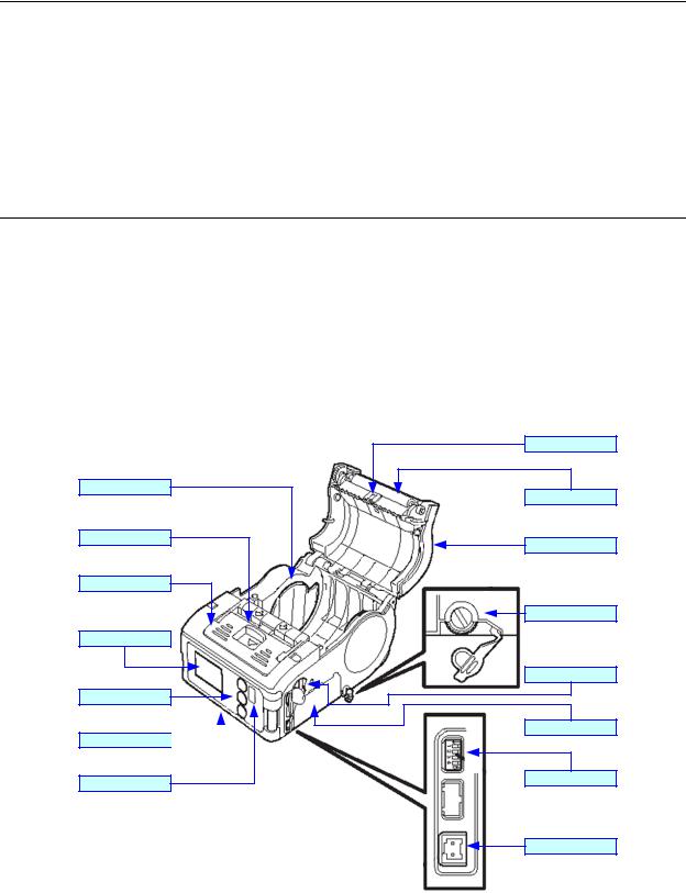
Label Guide
Open/Close Lever
Dispenser Unit
LCD Display
Function Keys
Front Housing Cover 

IrDA Filter
Eye-Mark Sensor
Platen Roller
Top Housing Cover
Label Guide Dial
RS232C Port
Battery Compartment
Dip Switches
DC Power Port
Figure 1-1, Primary Features & Components
SATO MB2i Service Manual |
PN 9001145B |
Page 1-3 |

Unit 1: Introduction
SWITCHES AND INDICATORS
The table below identifies and defines printer switches and indicators for operator interface. The accompanying graphics display their locations and appearance
|
SWITCHES |
Power Button |
Two position on/off switch that controls power flow to the system. |
|
|
Print Button |
Two position on/off button that activates and deactivates print action. |
Feed Button |
Two position on/off button that activates and deactivates feed action. |
|
INDICATORS |
Charge LED |
Indicates the resource level of the power pack. |
Status LED |
Indicates the systems’ operational status. |
|
DIP SWITCHES |
1 through 4 |
Various positions of the four accumilatively decides some printer |
|
configuration activities. |
SATO MB2i Service Manual |
PN 9001145B |
Page 1-4 |

TECHNICAL DATA
•Physical Characteristics
•Enviromental
•Power
•Processing
•Sensing
•Regulatory Approvals
•Interface Modules
•Media
•Character Font Capabilities
•Barcode Capabilities
SATO MB2i Service Manual |
PN 9001145B |
Page 2-1 |

Unit 2: Technical Data
PHYSICAL CHARACTERISTICS
Height (maximum) |
2.87 Inches (73 mm) |
|
|
|
|
Width (maximum) |
3.47 Inches (88 mm) |
|
|
|
|
Depth (maximum) |
5.04 Inches (128 mm) |
|
|
|
|
Weight (maximum) |
MB200i: 405 Grams (includes 105 grams for battery bag) |
|
MB201i: 390 Grams (includes battery) |
||
|
||
|
|
|
Drop Specification |
9.84 Feet (3.0 m) all six sides |
|
|
|
ENVIRONMENTAL
Operating Temperature |
5° to 122°Fahrenheit (-15° to 50°C) |
|
|
Storage Temperature |
-13° to 140°Fahrenheit (-25° to 60°C) |
|
|
Storage Humidity |
30 to 90% RH Non-Condensing |
|
|
Operating Humidity |
30 to 80% RH Non-Condensing |
|
|
POWER
Print Capacity |
Four rolls with full charge (equivalent of 48 meters). Continuous |
|
printing is permitted (provided print duty is 16% or less). |
||
|
||
|
|
|
Battery |
Lithiun ion 7.4 volts, 2400mAh standard pack |
|
|
|
|
AC Adapter |
DC 9 Volt |
|
|
|
PROCESSING
CPU |
32 Bit RISC |
|
|
Flash ROM |
2 Megabytes |
|
|
Receive Buffer |
12 Kilobytes |
|
|
SENSING
Gap/Dispense |
Fixed |
|
|
Reflective Eye-Mark |
Fixed |
|
|
Label |
Fixed |
|
|
Head-Open |
Yes |
|
|
REGULATORY APPROVALS
Safety |
UL 60950 |
|
|
EMC |
FOC, Class B |
|
|
Wireless LAN |
R & TTE (FOC15B, FOC15C) |
|
|
Bluetooth |
R & TTE (FOC15B, FOC15C) |
|
|
SATO MB2i Service Manual |
PN 9001145B |
Page 2-2 |
Unit 2: Technical Data
Method |
Direct Thermal |
|
|
Speed (maximum) |
4.05 Inches Per Second (103 mm/s) (varies with print duty) |
|
|
Print Module (dot size) |
.0049 Inches (.125 mm) |
|
|
Resolution |
203 Dots Per Inch (8 dpmm) |
|
|
Maximum Print Width |
1.89 Inches (48 mm) |
|
|
Maximum Print Pitch |
6.30 Inches (160 mm) |
|
|
Angle |
0°, 90°, 180°, 270° |
|
|
INTERFACE MODULES
|
RS232C (9600 to 57,6000 dps) Standard |
Serial Port |
Ready/Busy or X-On/X-Off Flow Control |
|
Bi-Directional Status |
IrDA |
Ir. Std., BHT, Ir Comm (3-wire cooked), Ir Obex (optional) |
|
|
Ethernet |
802.11B Wireless Wi-Fi (with built-in display) |
|
|
Bluetooth |
Version 1.1 Compliant |
|
|
MEDIA
Media Types |
Super High Sensitive, Techno-Thermal A, Sythetic Paper Thermal |
|
C, Non-Sticky Thermal 64, Two-Color Thermal |
||
|
||
|
|
|
Linerless Media |
Standard (strong/weak adhesive) |
|
|
|
|
Media Thickness |
0.0025 to 0.0075 Inches (0.064 - 0.190 mm) |
|
|
|
|
Roll Media Outside Diameter |
2.64 Inches (67 mm +/- 0.5) MB200i only |
|
|
|
|
Wound |
Face In / Face Out. Face In is for linerless only. |
|
|
|
|
Core Size |
0.75 to 1.0 Inches ( 19.05-25.40 mm) internal diameter |
|
|
|
CHARACTER FONT CAPABILITIES
MATRIX FONTS
XU Font |
5 dots W x 9 dots H (Helvetica) |
|
|
XS Font |
17 dots W x 17 dots H (Univers Condensed Bold) |
|
|
XM Font |
24 dots W x 24 dots H (Univers Condensed Bold) |
|
|
OA Font (OCR-A) |
|
|
|
OB Font (OCR-B) |
|
|
|
AUTO SMOOTHING FONTS |
|
|
|
WB |
18 dots W x 30 dots H |
|
|
WL |
28 dots W x 52 dots H |
|
|
XB |
48 dots W x 48 dots H (Univers Condensed Bold) |
|
|
XL |
48 dots W x 48 dots H (Sans Serif) |
|
|
SATO MB2i Service Manual |
PN 9001145B |
Page 2-3 |

Unit 2: Technical Data
CHARACTER CONTROL
Expansion up to 12 x in either the X or Y coordinates. Charcter Pitch Control
Line Space Control Journal Print facility
0, 90, 180, and 270 Degree Rotation
BAR CODE CAPABILTIES
|
UPC-A/E |
|
|
EAN-13/8 |
|
|
NW-7 (Codabar) |
|
|
Code 39 |
|
Linear Bar Codes |
Code 93 |
|
|
Code 128 |
|
|
RSS-14 |
|
|
JAN/EAN |
|
|
ITF |
|
|
QR Code |
|
|
Data Matrix |
|
Two Dimemsional |
Maxicode |
|
|
PDF417 |
|
|
Composite Symbology |
|
|
|
|
Ratios |
1:2, 1:3, 2:5, User definable bar widths |
|
|
|
|
Bar Height |
4 to 999 dots, User progammable |
|
|
|
|
Rotation |
0, 90, 180, and 270 Degrees |
|
|
|
|
Sequential Numbering |
Sequential numbering of both numerics and bar codes |
|
|
|
|
Custom Characters |
RAM storage for special characters |
|
|
|
|
Expansion Ratio of Character |
Height: 1-12 times, Width: 1-12 times |
|
|
|
|
Graphics |
Full dot addressable graphics, SATO Hex/Binary, .BMP or |
|
.PCX formats |
||
|
||
|
|
|
Form Overlay |
Form overlay for high-speed editing of complex formats |
|
|
|
SATO MB2i Service Manual |
PN 9001145B |
Page 2-4 |

INTERFACE SPECIFICATIONS
•Interface Specifications
•AD-HOC Connectivity
SATO MB2i Service Manual |
PN 9001145B |
Page 3-1 |

Unit 3: Interface Secifications
INTERFACE SPECIFICATIONS
This chapter presents the printer interface types and their specifications. These specifications include detailed information to assist in the selection of the most appropriate method for the printer to interface with the host. The acceptable interface methods are:
•802.11B Wireless
•RS232C Serial
•Infrared Rays (IrDA)
•Bluetooth
Following the selection of the desired interface, proceed to the following unit for instructions on how to Configure the printer for that interface type.
WARNING: NEVER CONNECT OR DISCONNECT INTERFACE CABLES (OR USE A SWITCH BOX) WITH POWER APPLIED TO EITHER THE HOST OR THE PRINTER. THIS MAY CAUSE DAMAGE TO THE INTERFACE CIRCUITRY IN THE PRINTER/HOST AND IS NOT COVERED BY WARRANTY.
SATO MB2i Service Manual |
PN 9001145B |
Page 3-2 |

Unit 3: Interface Specifications
802.11B WIRELESS INTERFACE
802.11 refers to a family of specifications developed by the IEEE for wireless LAN technology to communicate between a wireless client and a base station or between two wireless clients. This interface only uses DSSS which allows wireless functionality comparable to Ethernet.
The wireless print server provides easy printer interface with 802.11b Wi-Fi compliant networks free of wired connections. Each printer is shipped with a Windows driver and interface installed. To print from a PC, the driver must be loaded and the PC must be configured to run one of the supported protocols.
Default Parameters: DSW1, 3, 4 OFF / DSW2 ON.
802.11B WIRELESS SPECIFICATIONS
Variable Data Rates |
11, 5.5, 2 and 1 Mbps |
Frequency Band |
2.4 GHz ISM Band |
Wired Equivalent Privacy & WPA |
WEP 128 bit, 64 bit (compatible with 40bit), WPA, 802.11x |
Sensitivity |
(typ, AAWGN, 8E-2 PER): -91dBm at 1Mbps, -88dBm at 2 Mdps, |
|
-87dBm at 5.5Mbps, -84dBm at 11Mbps. |
Range |
100m indoors, 300m outdoors |
Protocols |
TCP/IP, IPX/SPX, Direct Mode IPX/IP, DLC/LLC, NetBEUI, |
|
NetBIOS/IP |
SATO MB2i Service Manual |
PN 9001145B |
Page 3-3 |
Unit 3: Interface Secifications
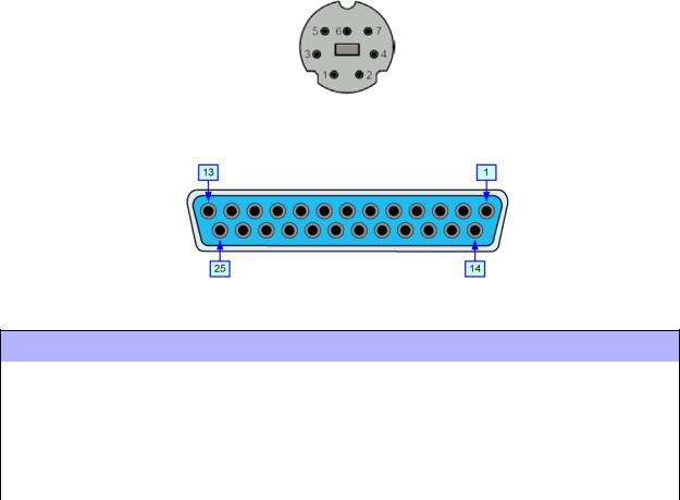
RS232C SERIAL INTERFACE
This interface is an industry standard for serially transmitting data using a wired cable. Separate transmit and receive lines enable data to flow in both directions simultaneously. Data transmitted using this protocol is defined in its parameters; baud/bps (speed), data bits, stop bit, parity, and hand-shaking method. To change the parameter settings, refer to the Programming Reference document for this product. The Programming Reference and a ready-made cable with DIN and DB9 connectors may be acquired from SATO.
Default Parameters: DSW1-4 OFF, 19200bps, 8 data bits, 1 stop bit, no parity.
Figure 3-1, RS232 Male Connector Pin Assignments
Figure 3-2, RS232 Female Connector Pin Assignments
READY/BUSY CABLE REQUIREMENTS
DB9 |
DB25 |
HOST |
DIRECTION |
8-PIN |
PRINTER |
|
|
|
|
|
|
2 |
3 |
RD (Receive Data) |
To Host |
1 |
TD (Transmit Data) |
|
|
|
|
|
|
3 |
2 |
TD (Transmit Data) |
To Printer |
6 |
RD (Receive Data) |
|
|
|
|
|
|
8 |
5 |
CTS (Clear To Send) |
To Printer DB9-6 |
2 |
RTS (Request To Send) |
|
|
|
|
|
|
5 |
7 |
SG (Signal Ground) |
Bi-Directional |
7 |
SG (Signal Ground) |
|
|
|
|
|
|
7 |
4 |
RTS (Request To Send) |
To Host |
5 |
CTS (Clear To Send) |
|
|
|
|
|
|
|
RS232C SPECIFICATIONS |
|
Asynchronous ASCII |
|
Half-duplex communication, Bi-Directional Communication |
Data Transmission Rate |
|
9600, 19200, 38400, 57600, 115200 bps |
Data Length |
|
8 bit (selectable) |
Stop Bit |
|
1 bit (fixed) |
Parity Bit |
|
ODD, EVEN, NONE (selectable) |
Codes Used |
|
ASC II Character Codes |
Control Codes |
|
STX (02h), ETX (03h), ACK (06h), NAK (15h) |
Connector |
|
8-pin mini - DIN |
Cable (8-pin DIN to 9-pin host) |
|
Call 704.644.1650 |
Signal Levels |
|
High: +12V, -12V |
SATO MB2i Service Manual |
PN 9001145B |
Page 3-4 |
Unit 3: Interface Specifications
INFRARED RAYS (IRDA)
Infrared communications is based on technology which is similar to entertainment remote control devices used in homes today. This technology offers a convient, interoperable, low power, and reliable way to connect computer and printer without the use of cables. The half-duplex, serial data interconnection capabilities supports walk up point-to-point use.
The infrared tranmission of print data is transferred from the terminal to the printer in four phases:
(1) Connection, (2) Printer Status Check, (3) Data Transfer, (4) Disconnection.
The limitations of this interface type is that it requires a direct line of sight with a reading span of 30 degrees at a maximum distance of 7-8 inches (20cm). When the peripherals are aligned, they negociate and transmit/receive data between the two devices.
Default Parameters: DSW1 ON / DSW2-4 OFF.
|
IRDA SPECIFICATIONS (STANDARD PROTOCOL) |
|
Baud Rate |
|
9600, 19200, 38400, 57600, 115200 |
Data Bit Length |
|
8 |
Stop Bit |
|
1 |
Parity Bit |
|
None, Odd, Even |
Codes Used |
|
ASC-II: 7 bit, Graphics: 8 bit. |
Control Codes |
|
STX (02h), SYN (16h), ETX (03h), DLE (10h) |
Communication Time |
|
Time-Out: 5.99 seconds, Retry: over 500 milliseconds. |
Receiving Type |
|
Single item. |
Operations Mode |
|
IrSIR v1.2 |
BHT protocol is the communication procedure used to transmit files between DENSO data collection devices by adopting the response method using the ACK/NAK codes defined for the use with these types of devices. Note the IrDA parameters must be set according to PDA/DCS methods and appropriately configured to direct data transmission to the printer. Refer to the IrDA command settings in the Programming Reference document for this printer, as well as, documentation provided by the manufacturer of the data collection device for the proper steps. The appropriate firmware must be installed to function.
|
IRDA SPECIFICATIONS (BHT PROTOCOL) |
|
Baud Rate |
|
9600, 19200, 38400, 57600, 115200 |
Data Bit Length |
|
8 |
Stop Bit |
|
1 |
Parity Bit |
|
None, Odd, Even |
Codes Used |
|
ASC-II: 7 bit, Graphics: 8 bit. |
Control Codes |
|
SOH (01h), STX (02h), ETX (03h), EOT (04h), ENQ (05h), ACK |
|
|
(06h), DLE (10h), NAK (15h). |
Communication Time |
|
Time-Out: 5.99 seconds, Retry: over 500 milliseconds. |
Receiving Type |
|
Single item. |
SATO MB2i Service Manual |
PN 9001145B |
Page 3-5 |
Unit 3: Interface Secifications
The IrCOMM protocol runs on top of IrDA and supports the emulation of a peer device similar to what’s connecting it by a serial or parallel cable for applications that access those ports through the operating system. Since various communication and printing applications utilize cables differently, cable emulation must account for those differences.
|
IRDA SPECIFICATIONS (IRCOMM PROTOCOL) |
|
Baud Rate |
|
9600, 19200, 38400, 57600, 115200 |
Data Bit Length |
|
8 |
Stop Bit |
|
1 |
Parity Bit |
|
None, Odd, Even |
Codes Used |
|
ASC-II: 7 bit, Graphics: 8 bit. |
Control Codes |
|
STX (02h), ETX (03h), ACK (06h), NAK (15h). |
Communication Time |
|
Time-Out: 5.99 seconds, Retry: over 500 milliseconds. |
Receiving Type |
|
Single item. |
Operations Mode |
|
3-wire cooked |
IrOBEX is a communictions protocol that facilitates the exchange of binary objects between devices and functions similar to HTTP in that a client uses a reliable transport to connect to a server to request or provide objects. The appropriate firmware must be installed for this to function.
This is a one-way communications protocol so therefore flow control and printer response are absent.
|
IRDA SPECIFICATIONS (IrOBEX PROTOCOL) |
|
Baud Rate |
|
9600, 19200, 38400, 57600, 115200 |
Data Bit Length |
|
8 |
Stop Bit |
|
1 |
Parity Bit |
|
None, Odd, Even |
Codes Used |
|
ASC-II: 7 bit, Graphics: 8 bit. |
Control Codes |
|
STX (02h), ETX (03h), ACK (06h), NAK (15h). |
Communication Time |
|
Time-Out: 5.99 seconds, Retry: over 500 milliseconds. |
Receiving Type |
|
Single item. |
SATO MB2i Service Manual |
PN 9001145B |
Page 3-6 |
Unit 3: Interface Specifications
BLUETOOTH
Bluetooth is a short-range, wireless technology operating in the unlicensed 2.4GHz band and offers greater flexibility than IrDA. Its signal is broadcast omni-directional and transmits/receives up to a distance 30 feet (10 meters).
Typically, the data is directed through a Bluetooth assigned COM port on a PDA which handles all COM port protocols. Refer to the manufacturer’s documentation PocketPC device setup.
Default Parameters: DSW1,3,4 OFF / DSW2 ON.
SATO MB2i Service Manual |
PN 9001145B |
Page 3-7 |

Unit 3: Interface Secifications
ALL INTERFACE TYPES
RECEIVE BUFFER
The data stream is received from the host to the printer one job at a time. This allows the software program to maintain control of the job print queue so that it can move a high priority job in front of ones of lesser importance.
The printer receives and prints one job at a time. If a print job exceeds the buffer size, transmission will be rejected by the printer. Error conditions that occur during the Print Data transmission will cause the printer to return a NAK.
ACK/NAK PROTOCOL
Bi-Directional ACK/NAK protocol is used for error control. In a normal transmission sequence when the transmission is received, the printer will return an ACK (06H) signifying that it was received without a transmission error. After the transmission command structure has been analyzed, a status byte is returned to the host. This status byte informs the host of the validity of the command structure.
If the command structure is error free, the printer proceeds with the print operation. When the print operation is completed, a Printer Status message is returned to the host. If an error was detected during the initial transmission sequence, a NAK (15H) will be returned signalling to the host that the received transmission contained errors and must be resent. If the returned Status byte indicates a command structure error, the error must then be corrected before the print data is resent to the printer.
A valid transmission to the printer must be bounded by an STX/ETX pair, with the STX (02H) signifying the start of the Print Data and ending with an ETX (03H) signifying the end.
SATO MB2i Service Manual |
PN 9001145B |
Page 3-8 |
Unit 3: Interface Specifications
AD-HOC CONNECTIVITY
To configure the printer for ad-hoc connectivity, an RS232 port and cable is initially required to use the Wireless Utility. The following two sections provides direction to the necessary tools, then procede to the next consecutive sections to begin setup.

 NOTE: An 8-pin DIN to 9-pin RS232 cable may purchased from SATO.
MB200i WIRELESS LAN CONFIGURATION TOOL (v1.0.0)
The software may be downloaded from: http://techsubweb.satoamerica.com/public/SAI_site/networking/MB/MB20xi_Cfgtool-setup.zip. Once downloaded, unzip the package and run “setup.exe” to begin installation. Upon completion, procede as follows: Start/Programs/Sato Tools/LAN Config Tool.
MB200i DRIVER
The driver may be downloaded from: http://techsuweb.satoamerica.com/public/SAI_site/drivers/ v4/SI_PORT.zip. Once downloaded, unzip the package and procede as follows: Control Panel/ Printer and Faxes/Add a Printer. Make the necessary entries on this menu screen to install the MB200i driver.
PRINTER SETUP
Perform the following procedure to configure the printer for ad-hoc interface connectivity.
1.Ensure all of the necessary tools are present.
2.Set all dipswitches to the OFF position to place the printer in the serial mode.
3.Connect the serial cable to the printer and the applicable host computer.
4.Power on the printer.
5.At the host computer, access Control Panel, followed by MB200i folder, and then click on MB200i Printer Driver.
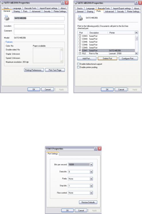
6.Procede to the SATO MB200i Properties screen (Figure 3-3a/b), then select the Ports tab.
SATO MB2i Service Manual |
PN 9001145B |
Page 3-9 |
Unit 3: Interface Secifications
Figure 3-3a/b, SATO MB200i Properties
7.Check the COM1: Serial Port option to assign “SATO MB200i” to that port, then click on Apply.
8.On the same screen, click on the Configure Port button.
9.When the COM1 Properties screen appears, click on each drop-down menu to change the settings as follows: 19200 Bits Per Second, 8 Data Bits, no Parity, 1 Stop Bit, no Flow Control. (Figure 3-4)
Figure 3-4, COM1 Properties
10.Click on the OK button to record the settings.
11.When the Properties screen appears, click on the OK button to record all settings.
12.When the main MB200i driver screen appears, click on its OK button.
SATO MB2i Service Manual |
PN 9001145B |
Page 3-10 |

Unit 3: Interface Specifications
13.Open the SATO MB200i Configuration Tool screen (Figure 3-5) and enter as follows:
•Select the Serial Port option for the interface type. Ensure COM1:19200,n,8,1 displays in the field to the right.
•IP Address: to 150.100.100.1, then press the SET button.
•Subnet Mask: to 255.255.255.0, then press the SET button.
•Gateway: to 0.0.0.0, then press the SET button.
•SSID: to MBPRINT, then press the SET button.
•Channel Number: to 11, then press the SET button.
•Operation Mode: to Ad-Hoc, then press the SET button.
•Security Mode: to Disable WEP, then press the SET button.
•Socket Port: to 9100, then press the SET button.
Figure 3-5, SATO MB200i Configuration Tool
14.Perform the following steps print a test label and verify the settings:
1.Power off the printer and change DSW2 to the ON position.
2Press and hold the FEED button while powering on the printer. Release when indicators are on.
3Press the FEED button again to print a test label. Press FEED again to stop.
4Ensure the contents of the label match those settings of step 13.
15.Ensure the contents of the label match those settings listed in step 13.
16.Repeat steps 2 through 15 if there is a discrepancy between the two.
SATO MB2i Service Manual |
PN 9001145B |
Page 3-11 |

Unit 3: Interface Secifications
COMPUTER SETUP
Perform the following procedure to configure the host computer for AD-HOC interface connectivity.
1.At the host computer, access Control Panel and then Network Connections.
2.When the Network Connections screen (Figure 3-6) appears, ensure the icon to the left of “Wireless Network Connection” does not have a red X over it. Proceed to step 3 if so, exit if not.
Figure 3-6, Network Connections
3.Click on the icon mentioned in step 2 to proceed to the Wireless Network Connection Properties screen (Figure 3-7a/b).
4.Click on the Wireless Networks tab to view that menu, then on the Advanced button.
Figure 3-7a/b, Wireless Network Connection Properties
SATO MB2i Service Manual |
PN 9001145B |
Page 3-12 |
Unit 3: Interface Specifications
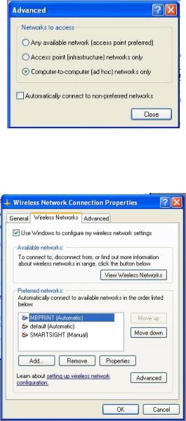
5.When the Advanced screen (Figure 3-8) appears, select the Computer-To-Computer option, followed by the Close button.
Figure 3-8, Advanced
6.When the Wireless Network Connection Properties Figure 3-9) screen reappears, click on the Add button to add a network matching that of the printer.
Figure 3-9, Wireless Network Connection Properties
7.When the Wireless Network Properties (Figure 3-10) screen appears, input MBPRINT in the Network Name (SSID) field.
8.Alter the following fields as necessary:
•Network Authentication: Open.
•Data Encryption: Disabled.
9.Press the OK button to enter the selections.
SATO MB2i Service Manual |
PN 9001145B |
Page 3-13 |
Unit 3: Interface Secifications
Figure 3-10, Wireless Network Properties
10.When the Wireless Network Connection Properties screen (Figure 3-9) appears, ensure that MBPRINT is displayed as the preferred network. If not, repeat steps 4 through 10.
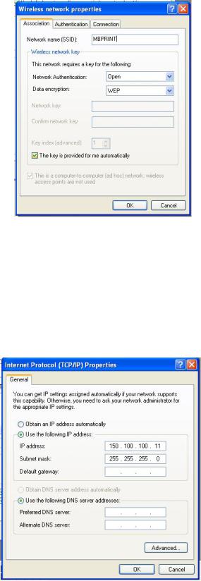
11.Click on the General tab to view that menu.
12.Scroll the “This connection uses” field to view the Internet Protocol (TCP/IP) option and select it.
13.When the Internet Protocol (TCP/IP) Properties screen (Figure 3-11) appears, select the “Use the following IP address” option to activate those items.
Figure 3-11, Internet Protocol (TCP/IP) Properties
SATO MB2i Service Manual |
PN 9001145B |
Page 3-14 |
Loading...