


Operator Manual
For printer model:
CG4 Series
CG408DT |
CG408TT |
CG412DT |
CG412TT |
Direct Thermal Type |
Thermal Transfer Type |
|
|
|
|
PN: 9001218C
Read this Operator Manual before using this product.
Keep this document available for future reference.
www.satoamerica.com
SATO America, Inc.
10350A Nations Ford Road
Charlotte, NC 28273
Main Phone: (704) 644.1650
Technical Support: (704) 644.1660
Technical Support Fax: (704) 644.1661 E-Mail: satosales@satoamerica.com techsupport@satoamerica.com www.satoamerica.com
Copyright 2011 SATO America, Inc. All rights reserved
Caution
(1)Reproduction in any manner of all or part of this document is prohibited.
(2)The contents of this document may be changed without prior notice.
(3)Great care has been taken in the preparation of this document. However, if, for any reason, if any problems, mistakes, or omissions are found, please contact your SATO reseller or technical support center.
FCC statement
The printer complies with the requirements in Part 15 of FCC Rules for a Class B Computing Device. Operating the printer in a residential area may cause unacceptable interference to radio and TV reception. If the interference is unacceptable, you can reposition the equipment, which may improve reception.
PN: 9001218C
Safety Precautions
Safety Precautions
Please read the following information carefully before installing and using the printer.
Pictographic Symbols
This instruction manual and the printer labels use a variety of pictographic symbols to facilitate safe and correct use of the printer and to prevent injury to others and property damage. The symbols and meanings for them are given below. Be sure to understand these symbols well before reading the main text.
Ignoring the instructions marked by this symbol and erroneously operating the printer could result
in death or serious injury.
Warning
|
Ignoring the instructions marked |
|
by this symbol and erroneously |
|
operating the printer could result |
Caution |
in injury or property damage. |
|
Example Pictographs
The  pictograph means “Caution is required.” A specific warning symbol is contained inside this pictograph (The symbol at left is for electric shock).
The  pictograph means “Should not be done.” What is specifically prohibited is contained in or near the pictograph (The symbol at left means “Disassembly prohibited”).
The  pictograph means “Must be done.” What is specifically to be done is contained in the pictograph (The symbol at left means “Unplug the power cord from the outlet”).
 Warning
Do not set on an unstable area
•Do not set on an unstable area, such as a wobbly table or slanted area or an area subject to strong vibration. If the printer falls off or topples over, it could injure someone.
Do not place containers full of water or other liquid on the printer
•Do not place flower vases, cups, or other containers holding liquids, such as water or chemicals, or small metal
objects near the printer. If they are spilled and get inside the printer, immediately turn off the power switch, unplug the power cord from the outlet, and contact your SATO reseller or technical support center. Using the printer in this condition could cause a fire or electric shock.
Do not put objects inside the printer
•Do not insert or drop in metal or burnable objects inside the printer’s openings (cable outlets, etc.). If foreign objects
do get inside the printer, immediately turn off the power switch, unplug the power cord from the outlet, and contact your SATO reseller or technical support center. Using the printer in this condition could cause a fire or electric shock.
Do not use other than the specified voltage
•Do not use other than the specified voltage. Doing so could result in fire or electric shock.
Always ground the connections
• Always connect the printer’s ground wire to a ground. Not
grounding the ground wire could result in electric shock.
Handling of the power cord
•Do not damage, break, or modify the power cord. Also, do not place heavy objects on the power cord, heat it, or pull it because doing so could damage the power cord and cause a fire or electric shock.
•If the power cord becomes damaged (core is exposed, wires broken, etc.), contact your SATO reseller or technical support center. Using the power cord in this condition could cause a fire or electric shock.
•Do not modify, excessively bend, twist, or pull the power cord. Using the power cord in such a condition could cause a fire or electric shock.
When the printer has been dropped or broken
•If the printer is dropped or broken, immediately turn off the power switch, unplug the power cord from the outlet, and contact your SATO reseller or technical support
center. Using the printer in this condition could cause a fire or electric shock.
Do not use the printer when something is abnormal about it
•Continuing to use the printer in the event something is
abnormal about it, such as smoke or unusual smells coming from it, could result in fire or electric shock. Immediately turn off the power switch, unplug the power cord from the outlet, and contact your SATO reseller or technical support center for repairs. It is dangerous for the customer to try to repair it, so absolutely do not attempt repairs on your own.
Do not disassemble the printer
• Do not disassemble or modify the printer. Doing so could
result in fire or electric shock. Contact your SATO reseller or technical support center to conduct internal inspections, adjustments, and repairs.
CG4 Series Operator Manual |
Page i |
Safety Precautions
|
Warning |
Regarding the cutter |
Using the head cleaning fluid |
• Do not touch the cutter with |
• Use of flame or heat around |
your hands or do not put |
the head cleaning fluid is |
something into the cutter. |
prohibited. Absolutely do not |
Doing so could result in an |
heat it or subject it to flames. |
injury. |
• Keep the fluid out of reach of |
|
children to prevent them from |
|
accidentally drinking it. If the |
|
fluid is drunk, immediately |
|
consult with a physician. |
 Caution
Do not place in areas with high humidity
•Do not place the printer in areas with high humidity or where condensation forms. If condensation forms, immediately turn off the power switch and do not use the printer until it dries. Using the printer while condensation is on it could result in electric shock.
Carrying the Printer
• When moving the printer,
always unplug the power cord
from the outlet and check to make sure all external wires are disconnected before moving it. Moving the printer with the wires still connected could damage the cords or connecting wires and result in a fire or electrical shock.
•Do not carry the printer with paper loaded in it. The paper could fall out and cause an injury.
•When setting the printer on the floor or a stand, make sure not to get your fingers or hands pinched under the printer feet.
Power supply
•Do not operate the power switch or plug in/unplug the power cord with wet hands. Doing so could result in electric shock.
Power cord
•Keep the power cord away from hot devices. Getting the power cord close to hot devices could cause the cord’s covering to melt and cause a fire or electrical shock.
•When unplugging the power cord from the outlet, be sure to hold it by the plug. Pulling it by the cord could expose or break the core wires and cause a fire or electric shock.
•The power cord set that comes with the printer is especially made for this printer. Do not use it with any other electrical devices.
Top cover
• Be careful not to get your
fingers pinched when opening or closing the top cover. Also be careful the top cover does not slip off and drop.
Print head
•The print head is hot after printing. Be careful not to get burned when replacing paper or cleaning immediately after
printing.
•Touching the edge of the print head immediately after printing could result in injury. Use caution when replacing the label or cleaning the print head.
•You should not replace the print head without having received the proper training.
Loading paper
• When loading roll paper, be careful not to get your fingers
pinched between the paper roll and the supply unit.
When not using the printer for a long time
• When not using the printer for a long time, unplug the power cord from the outlet to maintain safety.
During maintenance and cleaning
• When maintaining and
cleaning the printer, unplug the power cord from the outlet to maintain safety
Page ii |
CG4 Series Operator Manual |

Safety Precautions
Precautions for Installation and Handling
Printer operation can be affected by the printer environment.
Refer to the following instructions for installation and handling of CG4 Series printer.
Select a Safe Location
|
|
Do not place the printer in a location subject to |
Place the printer on a surface that is flat and level. |
|
water or oil. |
|
|
|
If the surface is not flat and level, this may result in poor print quality. This may also cause malfunction and shorten the life span of the printer.
Do not place the printer on a location that produces vibration.
Do not place the printer in a location where it will be splashed with water or oil. Water or oil entering inside the printer may cause a fire, electric shock, or malfunction.
Avoid dust.
Giving serious vibration or shock to the printer may cause malfunction and shorten the life span of the printer.
Dust build up may result in poor print quality.
Keep the printer out of high temperature and humidity.
Avoid locations subject to extreme or rapid changes in temperature or humidity.
Keep out of direct sunlight.
This printer has a built-in optical sensor. Exposure to direct sunlight will make the sensor less responsive and may cause the label to be sensed incorrectly.
Close the top cover when printing.
Power Supply
This printer requires an AC power supply.
Provide a stable source of electricity to the printer.
Be sure to connect the printer to an AC power supply via the supplied AC adapter.
Connect the power cord to a grounded power outlet.
Make sure that the printer is plugged into a grounded power outlet.
When using the printer, do not share its power outlet with other electrical devices that could result in power fluctuations and performance issues with your printer.
CG4 Series Operator Manual |
Page iii |
Safety Precautions
Page iv |
CG4 Series Operator Manual |
|
|
Table of Contents |
|
Table of Contents |
|
Introduction ................................................................................................................... |
1 - 1 |
|
1.1 |
Features of the Printer.................................................................................................... |
.. 1 - 1 |
1.2 |
Unpacking .................................................................................................................. |
...... 1 - 2 |
1.3 |
Parts Identification....................................................................................................... |
..... 1 - 3 |
Installation ..................................................................................................................... |
2 - 1 |
|
2.1 |
Site Location .............................................................................................................. |
...... 2 - 2 |
2.2 |
Media Selection............................................................................................................ |
.... 2 - 2 |
2.3 |
Loading Labels............................................................................................................. |
.... 2 - 3 |
2.4 |
Loading the Carbon Ribbon (For CG408TT, CG412TT only) .......................................... |
2 - 7 |
2.5 |
Connections ................................................................................................................ |
... 2 - 10 |
Operation and Configuration ....................................................................................... |
3 - 1 |
|
3.1 |
Operator Panel............................................................................................................. |
.... 3 - 2 |
3.2 |
Operating Modes............................................................................................................ |
.. 3 - 3 |
3.3 |
User Test Print Mode ....................................................................................................... |
3 - 4 |
3.4 |
Factory Test Print Mode................................................................................................... |
3 - 8 |
3.5 |
Operation Setting Mode ................................................................................................. |
3 - 11 |
3.6 |
Program Download Mode............................................................................................... |
3 - 13 |
3.7 |
Font Download Mode ..................................................................................................... |
3 - 15 |
3.8 |
Default Setting Mode...................................................................................................... |
3 - 16 |
3.9 HEX Dump Mode ........................................................................................................... |
3 - 17 |
|
3.10 Error Occurrence While Downloading.......................................................................... |
3 - 17 |
|
3.11 Printer Configurations Setting ...................................................................................... |
3 - 18 |
|
Troubleshooting............................................................................................................ |
4 - 1 |
|
4.1 |
Error signal troubleshooting ............................................................................................. |
4 - 2 |
4.2 |
Troubleshooting table...................................................................................................... |
. 4 - 4 |
4.3 |
Interface troubleshooting.................................................................................................. |
4 - 6 |
4.4 |
Test print troubleshooting................................................................................................. |
4 - 7 |
Cleaning and Maintenance........................................................................................... |
5 - 1 |
|
5.1 |
Cleaning The Print Head, Platen and Rollers................................................................... |
5 - 2 |
5.2 |
How To Clean The Printer (Cleaning Kit) ......................................................................... |
5 - 2 |
5.3 |
How To Clean The Printer (Cleaning Sheet).................................................................... |
5 - 3 |
5.4 |
Easy Replacement of Parts.............................................................................................. |
5 - 4 |
5.5 |
Adjusting Print Quality.................................................................................................... |
.. 5 - 7 |
General Specifications ................................................................................................. |
6 - 1 |
|
6.1 |
Printer Basic Specifications.............................................................................................. |
6 - 1 |
6.2 |
Optional Accessories Specifications ................................................................................ |
6 - 7 |
Interface Specifications................................................................................................ |
7 - 1 |
|
7.1 |
Interface types............................................................................................................ |
...... 7 - 1 |
7.2 |
RS232C Serial Interface................................................................................................... |
7 - 2 |
7.3 |
IEEE 1284 Parallel Interface ............................................................................................ |
7 - 6 |
7.4 |
Universal Serial Bus (USB) Interface ............................................................................... |
7 - 9 |
7.5 |
Local Area Network (LAN) Ethernet............................................................................... |
7 - 11 |
CG4 Series Operator Manual |
Page 1 |
Table of Contents
Appendix........................................................................................................................ |
8 - 1 |
|
8.1 |
Optional Accessories - Cutter........................................................................................... |
8 - 2 |
8.2 |
Optional Accessories - Dispenser .................................................................................... |
8 - 3 |
8.3 |
Positions of sensors and options...................................................................................... |
8 - 5 |
8.4 |
Operation Mode Selection................................................................................................ |
8 - 6 |
8.5 |
Base Reference Point ...................................................................................................... |
8 - 7 |
8.6 |
Offset position Adjustment ............................................................................................... |
8 - 9 |
8.7 |
Paper End ...................................................................................................................... |
8 - 10 |
8.8 |
Ribbon End .................................................................................................................... |
8 - 11 |
SATO Group of Companies ......................................................................................... |
9 - 1 |
SATO Group of Companies ................................................................................................... |
9 - 2 |
Page 2 |
CG4 Series Operator Manual |

Section 1: Introduction
INTRODUCTION
Thank you for your investment in this SATO printer product.
This Operators Manual contains the basic information about the installation, setup, configuration, operation and maintenance of the printer.
A total of eight topics are covered herein, and they are organized as follows:
Section 1: Introduction
Section 2: Installation
Section 3: Operation and Configuration Section 4: Troubleshooting
Section 5: Cleaning and Maintenance Section 6: General Specifications Section 7: Interface Specifications Section 8: Appendix
It is recommended that you read carefully and become familiar with each section before installing and maintaining the printer. Refer to the Table Of Contents at the front of this manual to search for the relevant information needed. All page numbers in this manual consist of a section number followed by the page number within the stated section.
This section assists you in unpacking the printer from the shipping container. You will also be guided through a familiarization tour of the main parts and controls.
The following information is provided herein:
•Features of the printer
•Unpacking
•Parts Identification
1.1FEATURES OF THE PRINTER
The CG4 Series is 4 inch Compact Desktop printer (Thermal Transfer or Direct Thermal). With a 32-bit RISC CPU, 4 ips print speed, and 4MB Flash Memory, the CG4 Series is an economical printer with numerous features making it suitable for a wide range of applications. The key features of the CG4 Series are:
•High Print Resolution with crisp printing quality (203dpi or 305dpi)
•Multiple Interface
•Cutter and Dispenser Printer Options
•Linerless Label Support
•Easy Media Loading
•Standalone Capability using Keypad
•Tool-less changing of print head and platen roller for easier maintenance
•Codepage Support and Emulations
•Safety Top Cover Latch
•Distinctive Chassis color
CG4 Series Operator Manual |
Page 1-1 |
Section 1: Introduction
1.2 UNPACKING
When unpacking the printer, take note of the following:
1.The box should stay right-side up. Lift the printer out of the box carefully.
2.Remove all the packaging from the printer.
3.Remove the accessory items from their protective containers.
4.Set the printer on a solid, flat surface. Inspect the shipping container and printer for any sign of damage that may have occurred during shipping. Please note that SATO shall hold no liability of any damage of any kind sustained during shipping of the product.
Notes
•If the printer has been stored in the cold, allow it to reach room temperature before turning it on.
•Please do not discard the original packaging box and cushioning material after installing the printer. They may be needed in future, if the printer needs to be shipped for repairs.
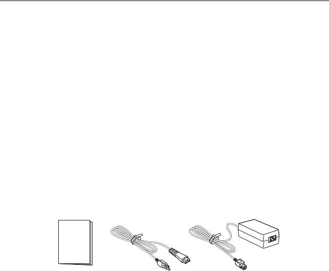
1.2.1 Included Accessories
After unpacking the printer, verify that you have the following materials:
User Documents |
|
|
(Quick Guide, Warranty, etc) |
Power plug* |
AC adapter |
* The shape of the power plug may vary, depending on the location where it was purchased.
Page 1-2 |
CG4 Series Operator Manual |
Section 1: Introduction
1.3 PARTS IDENTIFICATION
Front view
1
5
2 |
6 |
7
3
8
4 
1Operator panel
It consists of two contact buttons and two LED indicators (green and red).
2Top cover
Open this cover to load the media and ribbon.
3Cover open/close latch
Pull these latches on both sides of the printer forward to open the Top cover of the printer.
4Media ejection slot
Opening for media output.
5POWER button
Press this button to turn the power on or off.
6FEED/LINE button
7ERROR LED indicator
The LED lights or blinks red when an error is detected in the printer.
During printer configuration setting, the ERROR indicator responses in conjunction with the ON LINE (POWER) indicator to show the modes of the printer.
8ON LINE (POWER) LED indicator
The LED lights green when the printer is online and blinks green when the printer is offline.
During printer configuration setting, the ON LINE (POWER) indicator responses in conjunction with the ERROR indicator to show the modes of the printer.
Press this button to select the printer status (online/ offline) or to feed the media.
CG4 Series Operator Manual |
Page 1-3 |
Section 1: Introduction
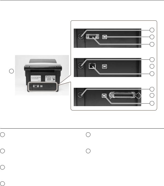
1.3 PARTS IDENTIFICATION (cont’d)
Back view
USB and RS232C interface on-board
10
11
12
USB and LAN interface on-board
10
 11
11
9 
13
USB and IEEE interface on-board
10
 14
14
11
9 Media inlet |
13 LAN interface terminal |
An opening for Fan-folded media or media from unwinder to feed in to the printer.
To connect printer to the host computer using LAN interface.
10 DC input power terminal |
14 IEEE interface terminal |
Supplies power to the printer by inserting the power cable via the AC adapter.
To connect printer to the host computer using IEEE interface.
11USB interface terminal
To connect printer to the host computer using the USB interface.
12RS-232C interface terminal
To connect printer to the host computer using RS-232C interface.
Or, to connect the optional Keypad, Scanner or Smart keyboard to the printer.
Page 1-4 |
CG4 Series Operator Manual |
Section 1: Introduction
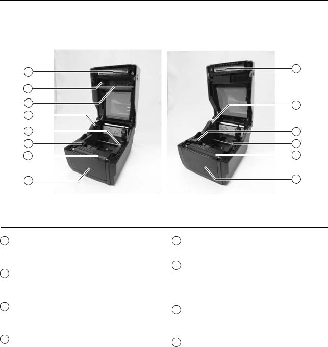
1.2 PARTS IDENTIFICATION (cont’d)
Internal view when Top cover is opened
15 |
15 |
|
|
16 |
|
17 |
18 |
18 |
|
19 |
20 |
20 |
19 |
21 |
21 |
22 |
22 |
CG408TT/ CG412TT |
CG408DT/ CG412DT |
15Print head
This component is used to print on the media. Perform maintenance at regular intervals.
16Ribbon unit
Used to load the ribbon and wind up the used ribbon.
17Pull out lever
This is used to pull out the ribbon unit from the top cover for ribbon loading.
18Roll media holder
To hold the roll media.
19Media guide slide lever
Set to meet the size of the media used.
20Media guide and I-Mark/ Gap sensor
A guide for the media to feed properly.
Detects the I-Mark on the media or gap of the label.
21Platen roller
This roller feeds the media. Perform maintenance at regular intervals.
22Optional device compartment
Used to install optional cutter or dispenser unit.
CG4 Series Operator Manual |
Page 1-5 |
Section 1: Introduction
This page is intentionally left blank
Page 1-6 |
CG4 Series Operator Manual |

Section 2: Installation
INSTALLATION
This section assists you in installing consumable media in the printer, as well as adjustment instructions and installing other optional attachment units.
The following information is provided:
•2.1 Site Location
•2.2 Media Selection
•2.3 Loading Labels
•2.4 Loading the Carbon Ribbon (For CG408TT, CG412TT only)
•2.5 Connections
CG4 Series Operator Manual |
Page 2-1 |

Section 2: Installation
2.1 SITE LOCATION
Consider the following when setting up the printer:
•Place the printer on a solid flat surface with adequate space. Make sure there is enough space above the printer to provide clearance for the top cover to swing open.
•Place it away from hazardous materials or dusty environments.
•Place it within operational distance of the host computer, within interface cable specifications.
2.2MEDIA SELECTION
The size and type of the labels or paper to be printed should have been taken into consideration before printer purchase. Ideally, the media width will be equal to, or just narrower than, the print head. Using media that does not cover the print head will allow the platen roller to tread on it and wear it out. The media edge will also wear a groove in the platen roller, which can affect print quality.
Note:
For optimal print performance and durability, please use SATO-certified label and ribbon supplies on this printer. Using supplies not tested and approved for use by SATO can result in unnecessary wear and damage to vital parts of the printer, and may void the warranty.
This printer can print on roll media or fan-folded media. The methods used for loading roll media and fanfolded media differ. The printer uses sensors to detect I-Marks or gap on the media in order to precisely position the print content.
Face-in Roll media |
Face-out Roll media |
Fan-fold media |
|
Front side |
1.5 mm |
|
Front side |
|
|
Paper feed direction |
|
Paper feed direction |
1.5 mm |
|
Label gap/ |
|
|
Label gap/ |
|
|
I-Mark |
3 mm |
I-Mark |
3 mm |
|
|
|
|
|
|||
|
Gap (spacing) |
|
Gap (spacing) Fold perforation |
||
|
Reverse side |
I-Mark |
|
Reverse side |
I-Mark |
Front side
Paper feed direction
l-Mark paper
Reverse side |
I-Mark |
Page 2-2 |
|
CG4 Series Operator Manual |
|
||
|
||
|
Section 2: Installation
2.3 LOADING LABELS
2.3.1 Loading Roll media
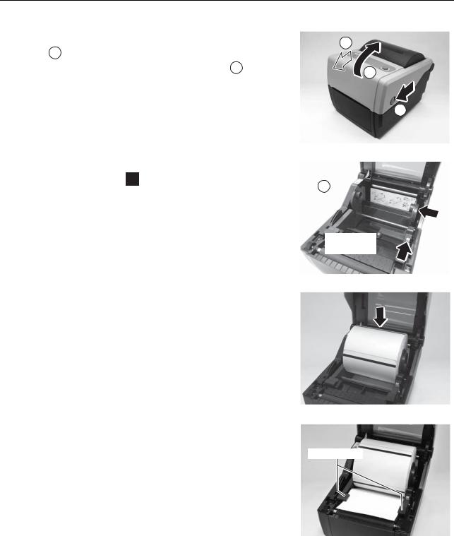
1.With the power supply off, pull the cover open/close latches 1 on both sides of the printer toward you to unlock the top cover, and then open the top cover 2 .
Note:
Make sure that the cover rests firmly so that it will not fall forward and injure your hands.
2.While holding the media guide slide lever, adjust the width of the media holder 1 to match the media size.
3. Load the media onto the media holder.
4.After pulling out the media, pass the media through the media guides and place the leading edge of the media on top of the platen roller.
Note:
Make sure the printed side of the media is facing upwards.
1
2
1
1 
Media guide  slide lever
Media guides
Printed side should face upwards
CG4 Series Operator Manual |
Page 2-3 |

Section 2: Installation
2.3 LOADING LABELS (cont’d)
5.Close the top cover until it clicks into position.
Notes:
•Be careful not to get your fingers pinched while closing the top cover.
•If the optional cutter or dispenser has been purchased, see Section 8.1 Optional Accessories - Cutter and Section 8.2 Optional Accessories - Dispenser on how to route the media.
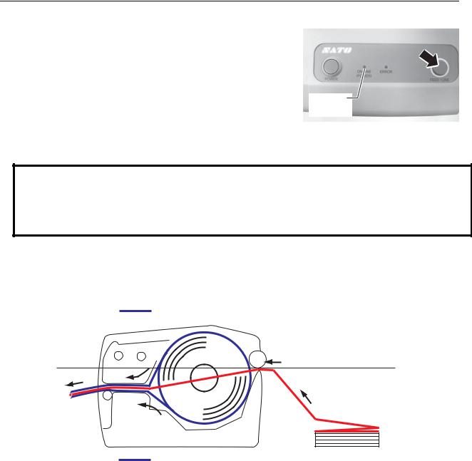
6.After loading the media, turn on the power.
The printer is online and the ON LINE (POWER) indicator lights green.
When the printer is ready, press the FEED/LINE button to output the leading part of the media.
ON LINE (POWER)
 Caution
•When replacing media, bear in mind that the print head and its surrounding area remain hot. Keep your fingers away from these areas to prevent injury.
•Avoid touching even the edge of the print head with your bare hands.
Page 2-4 |
CG4 Series Operator Manual |

Section 2: Installation
2.3 LOADING LABELS (cont’d)
2.3.2 Loading Fan-folded media
1.With the power supply off, pull the cover open/close latches on both sides of the printer toward you to unlock the top cover, and then open the top cover.
Note:
Make sure that the cover rests firmly so that it will not fall forward and injure your hands.
2.Pass the fan-folded media through the opened window at the rear of the unit.
Note:
Make sure the printed side of the media is facing upwards.
3.While holding the media guide slide lever, adjust the
width of the media holder 1 to match the media size. After pulling out the media, pass the media through the media guides and place the leading edge of the media on top of the platen roller.
4.Close the top cover until it clicks into position.
Notes:
•Be careful not to get your fingers pinched while closing the top cover.
•If the optional cutter or dispenser has been purchased, see Section 8.1 Optional Accessories - Cutter and Section 8.2 Optional Accessories - Dispenser on how to route the media.
1
2
1
1 
Media
guides
 Media holder slide lever
CG4 Series Operator Manual |
Page 2-5 |
Section 2: Installation
2.3 LOADING LABELS (cont’d)
5.After loading the media, turn on the power.
The printer is online and the ON LINE (POWER) LED lights green.
When the printer is ready, press the FEED/LINE button to output the leading part of the media.
ON LINE (POWER)
 Caution
•When replacing media, bear in mind that the print head and its surrounding area remain hot. Keep your fingers away from these areas to prevent injury.
•Avoid touching even the edge of the print head with your bare hands.
2.3.3Overview of the Roll media and Fan-folded media loading path
Roll media (Face-out)
Roll media (Face-in) |
Fan-fold media |
|
(Printed side face up) |
||
|
Page 2-6 |
CG4 Series Operator Manual |
Section 2: Installation
2.4 LOADING THE CARBON RIBBON (FOR CG408TT, CG412TT ONLY)
The CG408TT and C412TT printers enable two types of printing, Thermal transfer and Direct thermal. Thermal transfer paper media requires the use of carbon ribbon for print application. In such a scenario, it is the carbon ribbon that contains the ink that will be transferred to the media. Direct thermal paper media has a coating on the surface that is made visible through the application of heat from the print head. In this case, there is no need of loading the carbon ribbon.
1.With the power supply off, pull the cover open/close latches on both sides of the printer toward you to unlock the top cover, and then open the top cover.
Note:
Make sure that the cover rests firmly so that it will not fall forward and injure your hands.
2.Pull the lever on the middle of the ribbon unit downward to pull out the ribbon unit.
Then simply let down the ribbon unit. There is a stopper midway through its movement range that will prevent the ribbon unit from snapping down.
1
2
1
Lever
Ribbon unit
CG4 Series Operator Manual |
Page 2-7 |
Section 2: Installation
2.4 LOADING THE CARBON RIBBON (FOR CG408TT, CG412TT ONLY) (cont’d)
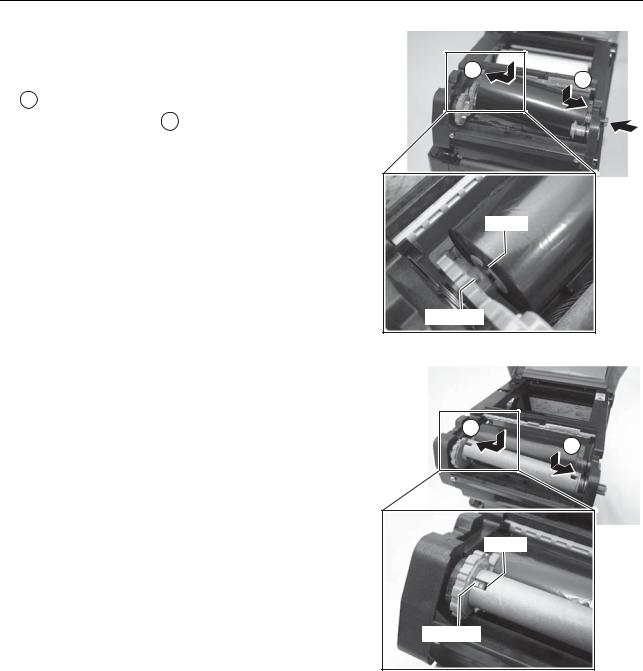
3. Open the carbon ribbon package, and then load the ribbon in the ribbon supply unit.
With the ribbon winding in clockwise direction, push in the ribbon roll to the right side of the ribbon supply unit
1 . Then fix the other side of the ribbon roll to the left of the ribbon supply unit 2 . Turn the ribbon roll until the
core snaps on the protrusion of the left ribbon supply unit.
Note:
Use only genuine SATO carbon ribbons for maximum print quality and printer durability.
4.Mount the empty ribbon core on the ribbon wind-up unit the same manner as in step 3 above.
When loading the carbon ribbon for the first time, use the empty ribbon core supplied with the printer. However, the subsequent ribbon core can be obtained from the last used up ribbon roll.
2
1
groove
protrusion
2
1
groove
protrusion
Page 2-8 |
CG4 Series Operator Manual |

Section 2: Installation
2.4 LOADING THE CARBON RIBBON (FOR CG408TT, CG412TT ONLY) (cont’d)
5. From the ribbon supply unit, pass the carbon ribbon |
|
|
underneath the print head assembly to the ribbon |
|
|
tape |
||
wind-up unit. |
||
|
||
Affix the carbon ribbon to the ribbon core using adhesive |
|
|
tape, and wind it up several times in the direction shown |
|
|
by the turn arrow. |
|
|
Confirm that the ribbon has been loaded as shown in the |
|
|
figure below or as illustrated on the inner side of the top |
|
|
cover. |
|
Ribbon route
Note:
The dull side (ink side) of the ribbon should be facing outward as it travels through the print head assembly.
6.Close the top cover until it clicks into position.
Note:
•Be careful not to get your fingers pinched while
closing the top cover.
7.After loading the media and the carbon ribbon, do a test print to check that the media roll and ribbon have been loaded properly. See Section 3.3 User Test Print Mode for instructions on how to run test print.
 Caution
•When replacing carbon ribbon, bear in mind that the print head and its surrounding area remain hot. Keep your fingers away from these areas to prevent injury.
•Avoid touching even the edge of the print head with your bare hands.
CG4 Series Operator Manual |
Page 2-9 |
Section 2: Installation
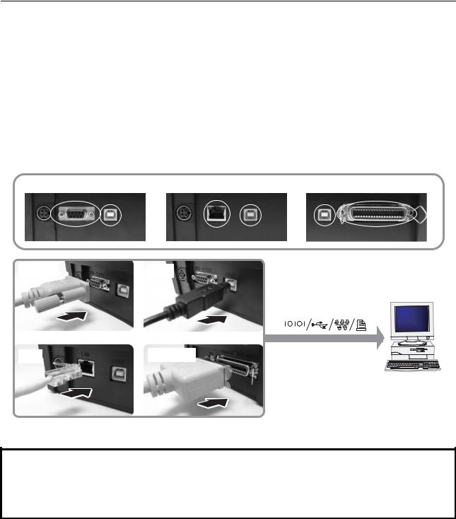
2.5 CONNECTIONS
This section explains the power cable and interface cable connection procedures.
2.5.1 Standard interface connection
CG4 Series printers have three types of Main PCBs, and each type of PCB is equipped with different types of interface to perform data communication with the host. These are described as follows.
1)RS232C and USB interface on-board
2)LAN and USB interface on-board
3)USB and IEEE 1284 interface on-board
Connect only one type of interface cable from the printer to the host computer. Use the cable that is compatible with the standard of the interface board as stated in Section 7: Interface Specifications. Make sure the cable is correctly oriented.
RS232C and USB interface on-board |
LAN and USB interface on-board |
USB and IEEE 1284 interface on-board |
RS232C |
USB |
Host
LAN |
IEEE 1284 |
 Caution
Never connect or disconnect interface cables (or use a switch box) with power applied to either the host or printer. This may caused damage to the interface circuitry in the printer/ host and is not covered by warranty.
Page 2-10 |
CG4 Series Operator Manual |

Section 2: Installation
2.5 CONNECTIONS (cont’d)
2.5.2 To activate the connected interface
After connection, you need to configure the printer to operate on the connected interface.
1.Please perform the procedures to set the appropriate interface mode as describe in Section 3.5 Operation Setting Mode.
2.In step 3 of this procedure, briefly press the FEED/LINE button repeatedly to select the interface mode according to your connection.
Connected Interface |
|
|
|
|
USB |
RS-232C |
|
|
LAN |
IEEE 1284 |
||||||||||
|
|
|
|
|
|
|
|
|
|
|
|
|
|
|
|
|
|
|
|
|
ON LINE (POWER) |
|
|
|
|
|
|
|
|
|
|
|
|
|
|
|
|
|
|
|
|
indications |
Blinks in green |
flashes green in a long interval |
||||||||||||||||||
|
|
|
|
|
|
|
|
|
|
|
|
|
|
|
|
|
|
|
|
|
ERROR |
|
|
|
|
|
|
|
|
|
|
|
|
|
|
|
|
|
|
|
|
indications |
Blinks in red |
|
|
|
Off |
|
||||||||||||||
|
|
|
|
|
|
|
|
|
|
|
|
|
|
|
|
|
|
|
|
|
2.5.3 Connecting the optional keypad/Scanner/Smart keyboard
The optional keypad, scanner or smart keyboard can be connected to the CG4 Series printer with RS-232C interface terminal, thus providing a stand-alone function. This function offers advanced features of Format Registration or Call Function without connecting to a host computer. You can use either Label Gallery or SBPL commands for the format registration. As for the data required for call function, capture it as a barcode with a scanner connected with CG4 Series printer.
1.Make sure that power cable is not connected to the printer.
2.Connect the cable from the optional device to the RS232C terminal at the back of the printer.
Note:
Make sure the connector is correctly oriented. Secure the printer with one hand, and insert the connector firmly.
3.Set the printer for use with the connected device. Refer to Section 3.5 Operation Setting Mode and perform the procedures to set the printer to Keypad mode or
Scanner/ Smart keyboard mode accordingly.
In step 3 of this procedure, briefly press of the FEED/ LINE button repeatedly until the respective lighting sequence of the ON LINE (POWER) and ERROR indicator is displayed.
Notes:
•If Keypad or Scanner/Smart keyboard mode is selected, even if the device is not connected, other interfaces cannot be activated.
•Only compatible scanner, compatible smart keyboard and SATO keypad can be connected to CG4 Series printer. Refer to SATO sales representative for more details.
An example of optional keypad connection to the printer.
CG4 Series Operator Manual |
Page 2-11 |
Section 2: Installation
2.5 CONNECTIONS (cont’d)
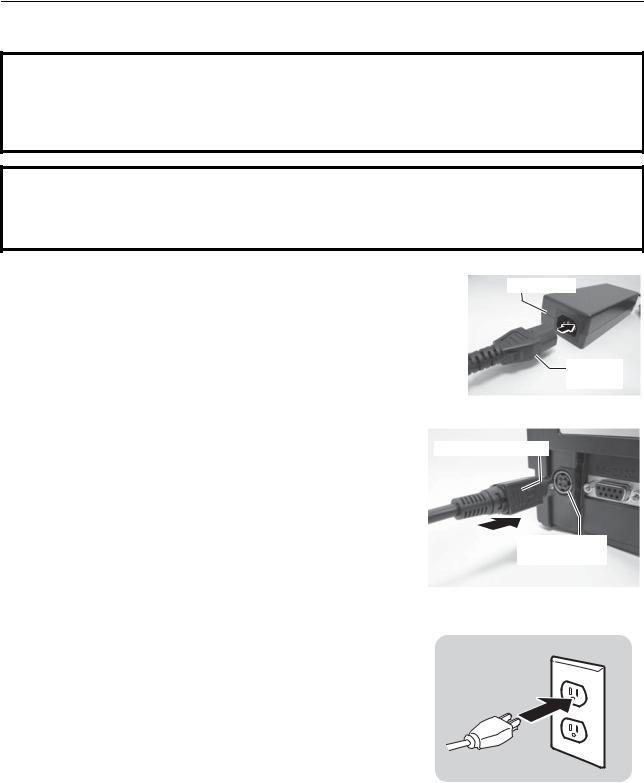
2.5.4 Connecting the Power Cable
 Warning
•Be sure to connect the ground wire. Failure to do so may cause an electric shock.
•Do not operate the power switch or insert/remove the power cable while your hands are wet. Doing so may cause an electric shock.
 Caution
The power cable and the AC adapter provided with this printer are for use with this printer only. They cannot be used with other electrical devices.
1. Connect the AC power cable to the AC adapter.
AC adapter
AC power plug
2. Connect the DC power plug from the AC adapter to the
DC input power terminal on the back of the printer. Flat side faces right. Make sure the flat side of the DC power plug is facing
right. Secure the printer with one hand, and insert the cable firmly.
DC input power terminal
3.Insert the AC power plug into a AC power outlet. Make sure that the AC voltage of your region is within the range of AC 100 to 240V, 50/60 Hz.
A 3-pin plug is attached to the power cord provided with your printer. One of these pins is the ground wire.
You must use a 3-pin power outlet. The plug will not work with a 2-pin power outlet.
* The shape of the power plug may vary depending on the location where the printer was purchased.
Page 2-12 |
CG4 Series Operator Manual |
Section 2: Installation
2.5 CONNECTIONS (cont’d)
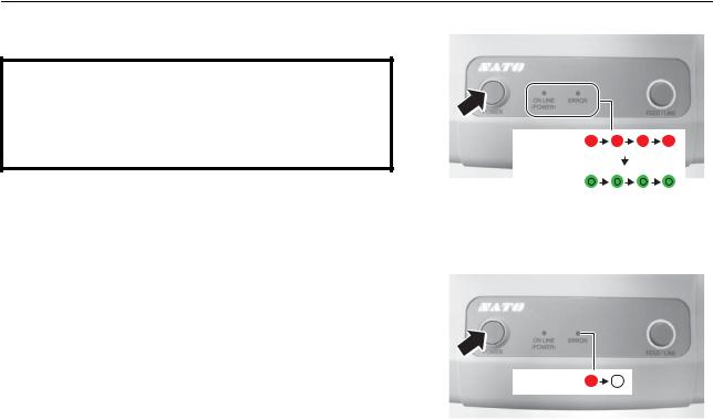
2.5.5 Turning On the Power
 Warning
Do not operate the power switch or insert/remove the power cable while your hands are wet. Doing so may cause an electric shock.
Press the POWER on the operation panel of the unit.
The ERROR indicator displays red, then after a single beep sound, the ON LINE (POWER) indicator displays green.
ERROR
Beep
sound
ON LINE (POWER)
2.5.6 Turning Off the Power
When you have completed the printing job, turn the printer off.
Be sure to confirm that the printer is in the offline status. Press and hold the POWER button until the ERROR indicator displays red and then turns off.
If there is any printed paper remaining in the printer, ERROR cut it off.
CG4 Series Operator Manual |
Page 2-13 |
Section 2: Installation
This page is intentionally left blank
Page 2-14 |
CG4 Series Operator Manual |

Section 3: Operation and Configuration
OPERATION AND CONFIGURATION
Before using the printer, it is best to read this manual thoroughly. Otherwise, you may disturb default settings on which the instructional procedures in this manual are based.
Most of the printer’s settings are controlled via standard SBPL commands or by using the provided SATO Utilities Tool application.
Some printer settings may be manually configured via the POWER and FEED/LINE buttons with the ON LINE (POWER) indicator and ERROR indicator on the front of printer. All of the printer’s buttons are used either singularly, or together, to perform configuration activities. The instructions to these operations are described in this section.
CG4 Series Operator Manual |
Page 3-1 |
Section 3: Operation and Configuration
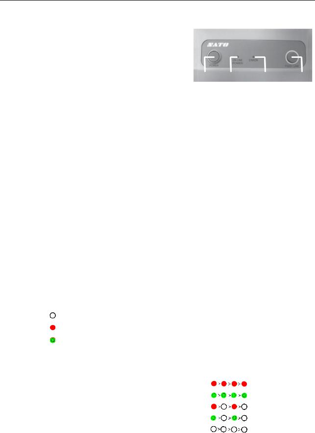
3.1 OPERATOR PANEL
The operator panel located on the top front, consists of two buttons and two LED indicators (red and green).
•POWER button
Press POWER button to turn on or off the printer. Press POWER button together with FEED/LINE button to enter various operating modes.
•FEED/LINE button
•Press FEED/LINE button during normal print operation to pause the printing and set the printer to offline mode. Press again to toggle the printer between the online and offline mode.
|
|
|
|
|
|
|
|
|
|
|
|
|
|
POWER |
|
ON LINE |
|
ERROR |
|
FEED/ |
|||||||
|
|
|
|
(POWER) |
|
|
|
|
LINE |
||||
•When printer idles in online mode, press the FEED/ LINE button to feed a blank label.
•During label feed, press the FEED/LINE button to pause label feed and go offline.
•The printer will go offline after opening and closing the top cover. Press the FEED/LINE button to make the printer go online.
•ON LINE (POWER) and ERROR indicators
When the printer is in normal mode, this two indicators notifies the user of various status conditions:
LED Indicator |
Color |
Functions |
|
|
|
|
|
|
ON LINE (POWER) |
Green |
Illuminates when printer is ready to receive data or is in printing |
|
|
mode (Online). |
|
|
Blinks when the printer is in offline mode. |
|
|
|
ERROR |
Red |
Illuminates or blinks when there is a system fault, for example, |
|
|
paper end. |
|
|
|
During different operation modes, the ON LINE (POWER) and ERROR indicators turn on and flash differently.
In this section, the combination of the following symbols has been used to describe the indicator lighting sequence. Refer to the example listed below for lighting sequences.
Indicator symbol |
Status |
|
|
|
|
|
Off |
|
|
|
Red light |
|
|
|
Green light |
|
|
The repeating patterns are as shown in the below examples. The sequences are indicated as from left to right. One LED Indication flash is approximately 200ms, and two indication flashes in a row are for about 400ms.
Example 1 |
Indicator: Red light. |
|
|
|
|
|
|
|
|
|
|
|
|
|
|
|
|
||||
|
|
|
|
|
|
|
|
|
|
|
Example 2 |
Indicator: Green light. |
|
|
|
|
|
|
|
|
|
|
|
|
|
|
|
|
||||
|
|
|
|
|
|
|
|
|
|
|
Example 3 |
Indicator: Blinking red light. |
|
|
|
|
|
|
|
|
|
|
|
|
|
|
|
|
||||
|
|
|
|
|
|
|
|
|
|
|
Example 4 |
Indicator: Blinking green light. |
|
|
|
|
|
|
|
|
|
|
|
|
|
|
|
|
||||
|
|
|
|
|
|
|
|
|
|
|
Example 5 |
Indicator: off |
|
|
|
|
|
|
|
||
|
|
|
|
|
|
|
|
|||
|
|
|
|
|
|
|
|
|
|
|
Page 3-2 |
CG4 Series Operator Manual |
 Loading...