


C L S eries “ e”
T hermal T rans fer P rinters
Operator and Technical
Reference Manual for
CL408e, CL412e, CL608e &
CL612e
PN 9001074 Preliminary

SATO ASIA PACIFIC PTE. LTD.
438A ALEXANDRA ROAD
#05-01/02 ALEXANDRA TECHNOPARK
SINGAPORE 119967
Tel: (65) 6271 5300
Fax: (65) 6273 6011
Sales Hotline: (65) 6276 2722
Service Hotline: (65) 6273 6455
Email: sales@satoasiapacific.com Website: www.satoworldwide.com
Copyright 2003
SATO Asia Pacific Pte. Ltd.
Warning : This equipment complies with the requirements in Part 15 of FCC rules for a Class A computing device. Operation of this equipment in a residential area may cause unacceptable interference to radio and television reception requiring the operator to take whatever steps necessary to correct the interference. All rights reserved. No part of this document may be reproduced or issued to third parties in any form whatsoever without the express permission of SATO Asia PacificPte. Ltd. The materials in this document are provided for general information andare subjected to change without prior notice. SATO Asia Pacific Pte. Ltd. assumes no responsibilities for any errors that may appear.

PREFACE
CL SERIES “e” PRINTER OPERATOR’S MANUAL
The CL Series “e” Printer Operator’s Manual contains basic information about the printer such as setup, installation, cleaning and maintenance. It also contains complete instructions on how to use the operator panel to configure the printer. The following is a brief description of each section in this manual.
SECTION 1. PRINTER OVERVIEW
This section contains a discussion of the printer specifications and optional features.
SECTION 2. INSTALLATION AND CONFIGURATION
This section contains instructions on how to unpack and set up the printer, load the labels and ribbon, and how to use the operator panel to configure the printer.
SECTION 3. CLEANING AND MAINTENANCE
This section contains instructions on how to clean and maintain the printer.
SECTION 4. PROGRAMMING
This section introduces the SATO printer programming language. It contains the commands that are used with the printer to produce labels with bar codes, alphanumeric data and graphics.
SECTION 5. INTERFACE SPECIFICATIONS
This section contains the printer’s interface specifications, which include detailed information on how to properly interface your printer to the host system.
SECTION 6. TROUBLESHOOTING
This section contains troubleshooting procedures to follow in the event you have printer problems.
SATO CL “e” Series Printers |
PN 9001074 Preliminary |
Page - i |
Preface
APPENDICES
APPENDIX A: Command Code Quick Reference
APPENDIX B: Bar Code Specifications
APPENDIX C: Custom Characters and Graphics
APPENDIX D: |
Optional Features |
APPENDIX E: Custom Protocol Command Codes
Page - ii |
PN 9001074 Preliminary |
SATO CL “e” Series Printers |

Preface
TABLE OF CONTENTS
SECTION 1. PRINTER OVERVIEW
Introduction . . . . . . . . . . . . . . . . . . . . . . . . . . . . . . 1- General Printer Specifications . . . . . . . . . . . . . . . . . . . . . 1- Character Fonts . . . . . . . . . . . . . . . . . . . . . . . . . . . . 1- Bar Codes . . . . . . . . . . . . . . . . . . . . . . . . . . . . . . . 1- Physical . . . . . . . . . . . . . . . . . . . . . . . . . . . . . . . . 1- Optional Accessories . . . . . . . . . . . . . . . . . . . . . . . . . 1-
SECTION 2. INSTALLATION AND CONFIGURATION
Introduction . . . . . . . . . . . . . . . . . . . . . . . . . . . . . . 2- Unpacking and Parts Identification . . . . . . . . . . . . . . . . . . 2- Setting Up the Printer . . . . . . . . . . . . . . . . . . . . . . . . . 2- Loading Labels, Tags and Ribbon in the CL608 and CL612 . . . . . . 2- Loading Labels, Tags and Ribbon in the CL408 and CL412 . . . . . . 2- Operator Panel . . . . . . . . . . . . . . . . . . . . . . . . . . . . 2-
CL608 and CL612 . . . . . . . . . . . . . . . . . . . . . . . . . 2- CL408 and CL412 . . . . . . . . . . . . . . . . . . . . . . . . . 2- Rear Panel. . . . . . . . . . . . . . . . . . . . . . . . . . . . . . . 2- CL608 and CL612 . . . . . . . . . . . . . . . . . . . . . . . . . 2- CL408 and CL412 . . . . . . . . . . . . . . . . . . . . . . . . . 2- Switches and Sensors . . . . . . . . . . . . . . . . . . . . . . . . . 2- CL608 and CL612 . . . . . . . . . . . . . . . . . . . . . . . . . 2- CL408 and CL412 . . . . . . . . . . . . . . . . . . . . . . . . . 2-
SECTION 3. CONFIGURATION
Printer DIP Switch Configuration . . . . . . . . . . . . . . . . . . . 3- Default Settings . . . . . . . . . . . . . . . . . . . . . . . . . . . . 3- Potentiometer Adjustments . . . . . . . . . . . . . . . . . . . . . . 3- LCD Panel Printer Configuration . . . . . . . . . . . . . . . . . . . 3- Normal Mode . . . . . . . . . . . . . . . . . . . . . . . . . . . 3- Advanced Mode . . . . . . . . . . . . . . . . . . . . . . . . . . 3- Card Mode . . . . . . . . . . . . . . . . . . . . . . . . . . . . . 3- Service Mode . . . . . . . . . . . . . . . . . . . . . . . . . . . 3- Counter Mode . . . . . . . . . . . . . . . . . . . . . . . . . . . 3- Test Print Mode . . . . . . . . . . . . . . . . . . . . . . . . . . 3- Default Setting mode . . . . . . . . . . . . . . . . . . . . . . . 3-
SATO CL “e” Series Printers |
PN 9001074 Preliminary |
Page - iii |

Preface
Clear Non-Standard Protocol Codes . . . . . . . . . . . . . . . . 3- Download User Defined Protocol Codes . . . . . . . . . . . . . . 3- Hex Dump Mode. . . . . . . . . . . . . . . . . . . . . . . . . . 3-
SECTION 4. CLEANING AND MAINTENANCE
Introduction . . . . . . . . . . . . . . . . . . . . . . . . . . . . . . 4- Procedures, CL608e and CL612e . . . . . . . . . . . . . . . . . . . 4-
Adjusting the Print Quality . . . . . . . . . . . . . . . . . . . . |
4- |
Darkness . . . . . . . . . . . . . . . . . . . . . . . . . . . . 4- |
|
Print Speed. . . . . . . . . . . . . . . . . . . . . . . . . . . 4- |
|
Cleaning the Print Head, Platen and Rollers . . . . . . . . . . . . |
4- |
Replacing the Print Head . . . . . . . . . . . . . . . . . . . . . |
4- |
Cleaning the Sensors . . . . . . . . . . . . . . . . . . . . . . . |
4- |
Replacing the Fuse. . . . . . . . . . . . . . . . . . . . . . . . . 4- |
|
Procedures, CL408e and CL412e . . . . . . . . . . . . . . . . . . . 4- |
|
Adjusting the Print Quality . . . . . . . . . . . . . . . . . . . . |
4- |
Darkness . . . . . . . . . . . . . . . . . . . . . . . . . . . . 4- |
|
Speed . . . . . . . . . . . . . . . . . . . . . . . . . . . . . |
4- |
Cleaning the Print Head and Platen . . . . . . . . . . . . . . . . 4- |
|
Replacing the Print Head . . . . . . . . . . . . . . . . . . . . . |
4- |
Cleaning the Sensors . . . . . . . . . . . . . . . . . . . . . . . |
4- |
Replacing the Fuse. . . . . . . . . . . . . . . . . . . . . . . . . 4-
SECTION 5. PROGRAMMING
Introduction . . . . . . . . . . . . . . . . . . . . . . . . . . . . . 5-1 |
|||||
The SATO CL Programming Language . . . . . . . . . . . . . . . . 5-1 |
|||||
Selecting Protocol Control Codes . . . . . . . . . . . . . . . . . . |
5-2 |
||||
Using Basic. . . . . . . . . . . . . . |
. . . . . |
. . . . . |
. . . . . |
. |
5-2 |
The Print Area . . . . . . . . . . . . |
. . . . . |
. . . . . |
. . . . . |
. |
5-4 |
Rotated Fields . . . . . . . |
. . . . . . . . . . . . . . . . |
. . . . . |
5-8 |
Command Default Settings |
. . . . . . . . . . . . . . . . |
. . . . . |
5-9 |
Command Codes . . . . . . . . . . . . . . . . . . . . . . . . . . 5-10 Bar Codes . . . . . . . . . . . . . . . . . . . . . . . . . . . . 5-11 Bar Codes, Expansion . . . . . . . . . . . . . . . . . . . . . . 5-16 Bar Codes, Variable Ratio . . . . . . . . . . . . . . . . . . . . 5-17 Base Reference Point . . . . . . . . . . . . . . . . . . . . . . 5-19 Characters, Custom Designed . . . . . . . . . . . . . . . . . . 5-21 Character Expansion . . . . . . . . . . . . . . . . . . . . . . 5-23 Character, Fixed Spacing . . . . . . . . . . . . . . . . . . . . 5-25 Character Pitch . . . . . . . . . . . . . . . . . . . . . . . . . 5-26 Character, Proportional Spacing . . . . . . . . . . . . . . . . 5-28 Clear Print Job(s) and Memory . . . . . . . . . . . . . . . . . 5-29
Page - iv |
PN 9001074 Preliminary |
SATO CL “e” Series Printers |
Preface
Continuous Forms Printing . . . . . . . . . . . . . . . . . . . 5-30 Copy Image Area . . . . . . . . . . . . . . . . . . . . . . . . 5-31 Cut. . . . . . . . . . . . . . . . . . . . . . . . . . . . . . . . . 5- Cut Job . . . . . . . . . . . . . . . . . . . . . . . . . . . . . . 5- Cut Last . . . . . . . . . . . . . . . . . . . . . . . . . . . . . . 5- Fonts, U, S, M, OA, OB, XU, XS and XM . . . . . . . . . . . . . . 5- Fonts, Raster. . . . . . . . . . . . . . . . . . . . . . . . . . . . 5- Fonts, Vector. . . . . . . . . . . . . . . . . . . . . . . . . . . . 5- Fonts, WB,WL, XB and XL . . . . . . . . . . . . . . . . . . . . . 5- Form Feed . . . . . . . . . . . . . . . . . . . . . . . . . . . . . 5- Form Overlay Recall . . . . . . . . . . . . . . . . . . . . . . . . 5- Form Overlay Store . . . . . . . . . . . . . . . . . . . . . . . . 5- Graphics, Custom . . . . . . . . . . . . . . . . . . . . . . . . . 5- Graphics, BMP . . . . . . . . . . . . . . . . . . . . . . . . . . . 5- Graphics, PCX . . . . . . . . . . . . . . . . . . . . . . . . . . . 5- Job ID Store . . . . . . . . . . . . . . . . . . . . . . . . . . . . 5- Job Name . . . . . . . . . . . . . . . . . . . . . . . . . . . . . 5- Journal Print. . . . . . . . . . . . . . . . . . . . . . . . . . . . 5- Lines and Boxes . . . . . . . . . . . . . . . . . . . . . . . . . . 5-
Line Feed . . |
. . . . . . . . . . . . . . . . . . . . . . . . . . . 5- |
|||
Media Size . . |
. . . . . . . . . . . . . . . . . |
. . . . . |
. . . . . |
5- |
Mirror Image |
. . . . . . . . . . . . . . . . . |
. . . . . |
. . . . . |
5- |
Off-Line . . . . . . . . . . . . . . . . . . . . . . . . . . . . . . 5- Postnet. . . . . . . . . . . . . . . . . . . . . . . . . . . . . . . 5- Print Darkness . . . . . . . . . . . . . . . . . . . . . . . . . . . 5- Print Length, Expanded . . . . . . . . . . . . . . . . . . . . . . 5-
Print Position . . . . . . . |
. . . . . . . . . . . . . . . . . . . . 5- |
||||||||
Print Quantity . . . . . . . . . . . . . . . . . . . . . . |
. . |
. |
. |
. 5- |
|||||
Print Speed . . . . . . . . |
. . . . . . . . . . . . . . . |
. . |
. |
. |
. 5- |
||||
Repeat Label . . . . . . . . |
. . . . . . |
. . . . |
. |
. . . . . . . . . |
5- |
||||
Replace Data (Partial Edit) |
. . . . . . |
. . . . |
. |
. . . . . . . . . |
5- |
||||
Reverse Image . . . . . . . . . . . . . . . . . . . . . . . . . . . 5- Rotate, Fixed Base Reference Point . . . . . . . . . . . . . . . . 5- Sequential Numbering . . . . . . . . . . . . . . . . . . . . . . . 5- Start/Stop Label . . . . . . . . . . . . . . . . . . . . . . . . . . 5- Calendar Option Commands. . . . . . . . . . . . . . . . . . . . 5-
Calendar Increment . . . . . . . . . . . . . . . . . . . . . . 5- Calendar Print . . . . . . . . . . . . . . . . . . . . . . . . . 5- Calendar Set . . . . . . . . . . . . . . . . . . . . . . . . . . 5- Expanded Memory Option Commands . . . . . . . . . . . . . . 5- Clear Expanded Memory . . . . . . . . . . . . . . . . . . . . 5- Select Memory Area . . . . . . . . . . . . . . . . . . . . . . 5- Fonts, TrueType Recall. . . . . . . . . . . . . . . . . . . . . 5- Fonts, TrueType Store . . . . . . . . . . . . . . . . . . . . . 5- Format/Field Recall . . . . . . . . . . . . . . . . . . . . . . 5- Form Overlay Recall . . . . . . . . . . . . . . . . . . . . . . 5-
Form Overlay Store
Format/Field Store. . . . . . . . . . . . . . . . . . . . . . . 5-
SATO CL “e” Series Printers |
PN 9001074 Preliminary |
Page - v |
Preface
Graphics, Custom Recall . . . . . . . . . . . . . . . . . . . . 5-
Graphics, Custom Store . . . . . . . . . . . . . . . . . . . . |
5- |
Graphics, BMP Recall . . . . . . . . . . . . . . . . . . . . . |
5- |
Graphics, BMP Store . . . . . . . . . . . . . . . . . . . . . . 5- |
|
Graphics, PCX Recall . . . . . . . . . . . . . . . . . . . . . . 5- |
|
Graphics, PCX Store . . . . . . . . . . . . . . . . . . . . . . 5- |
|
Initialize . . . . . . . . . . . . . . . . . . . . . . . . . . . . 5- |
|
Memory Area Select . . . . . . . . . . . . . . . . . . . . . . 5- |
|
Status . . . . . . . . . . . . . . . . . . . . . . . . . . . . . |
5- |
Custom Protocol Codes Download. . . . . . . . . . . . . . . . . 5- |
|
Two-Dimensional Symbols. . . . . . . . . . . . . . . . . . . . . 5- |
|
Data Matrix, Data Format . . . . . . . . . . . . . . . . . . . 5- |
|
Data Matrix, Data Print . . . . . . . . . . . . . . . . . . . . |
5- |
Dat Matrix Sequential Numbering . . . . . . . . . . . . . . . 5- |
|
Maxicode. . . . . . . . . . . . . . . . . . . . . . . . . . . . 5- |
|
PDF417 . . . . . . . . . . . . . . . . . . . . . . . . . . . . |
5- |
Configuration Commands . . . . . . . . . . . . . . . . . . . . . 5- |
|
Custom Protocol Download . . . . . . . . . . . . . . . . . . |
5- |
Printer Setting . . . . . . . . . . . . . . . . . . . . . . . . . |
5- |
Print Mode . . . . . . . . . . . . . . . . . . . . . . . . . . . 5- Print Type . . . . . . . . . . . . . . . . . . . . . . . . . . . 5- Pitch Offset. . . . . . . . . . . . . . . . . . . . . . . . . . . 5- Sensor Type . . . . . . . . . . . . . . . . . . . . . . . . . . 5- Serial I/F Parameters . . . . . . . . . . . . . . . . . . . . . 5-
SECTION 6. INTERFACE SPECIFICATIONS
Introduction . . . . . . . . . . . . . . . . . . . . . . . . . . . . . . 6- Interface Types . . . . . . . . . . . . . . . . . . . . . . . . . . . . 6-
The Receive Buffer . . . . |
. . . . . . . . . . . . . . . . . . . . . . 6- |
IEEE1284 Parallel Interface . . . . . . . . . . . . . . . . . . . . . . 6- |
|
Electrical Specifications |
. . . . . . . . . . . . . . . . . . . . . . 6- |
Data Streams . . . . . |
. . . . . . . . . . . . . . . . . . . . . . 6- |
Interface Pin Assignments . . . . . . . . . . . . . . . . . . . . . 6- |
|
RS232C Serial Interface . . . . . . . . . . . . . . . . . . . . . . . . 6- |
|
General Specifications . . . . . . . . . . . . . . . . . . . . . . . 6- |
|
Electrical Specifications
Pin Assignments . . . . . . . . . . . . . . . . . . . . . . . . . . 6- Ready/Busy Flow Control . . . . . . . . . . . . . . . . . . . . . 6- X-On/X-Off Flow Control . . . . . . . . . . . . . . . . . . . . . 6- Universal Serial Bus (USB) Interface . . . . . . . . . . . . . . . . . 6- Local Area Network (LAN) Interface . . . . . . . . . . . . . . . . . 6- Bi-Directional Communications . . . . . . . . . . . . . . . . . . . . 6- ENQ/ACK/NAK . . . . . . . . . . . . . . . . . . . . . . . . . . 6- Status Response . . . . . . . . . . . . . . . . . . . . . . . . . . 6- Accessory (EXT) Connector . . . . . . . . . . . . . . . . . . . . . . 6- Pin Assignments . . . . . . . . . . . . . . . . . . . . . . . . . . 6- Standard Operation . . . . . . . . . . . . . . . . . . . . . . . . 6-
Page - vi |
PN 9001074 Preliminary |
SATO CL “e” Series Printers |

Preface
Repeat Print . . . . . . . . . . . . . . . . . . . . . . . . . . . . 6- Error Signals . . . . . . . . . . . . . . . . . . . . . . . . . . . . 6-
SECTION 6. TROUBLESHOOTING
Initial Checklist . . . . . . . . . . . |
. . . . . . . . . . . . . . . . 7-1 |
|
Using the IEEE1284 Parallel Interface . . . . . . . . . . . . . . . . 7-1 |
||
Using the RS232C Serial Interface . . . . . . . . . . . . . . . . . . |
7-3 |
|
Error Signals . . . . . . . . . . . . . |
. . . . . . . . . . . . . . . . |
7-4 |
APPENDICES
APPENDIX A: Command Code Quick Reference
APPENDIX B: Bar Code Specifications
Bar Code Symbologies . . . . . . . . . . . . . . . . . . |
. . . . B-1 |
||
Codabar . . . . . . . |
. . . . . . . . . . . . . . . . |
. . . . B-2 |
|
Code 39. . . . . . . . . . . . . . . . . . . . . . . . |
. . . . B-3 |
||
Interleaved Two of Five (I 2/5). . . . . . . . . . . . |
. . . . B-4 |
||
UPC-A/EAN-13 . . . . . . . . . . . . . . . . . . . . |
. . . . B-5 |
||
EAN-8. . . . . . . . . |
. . . . . . . . . . . . . . . . |
. . . . B-6 |
|
Industrial Two of Five |
. . . . . . . . . . . . . . . . . . . . B-8 |
||
Matrix Two of Five . . . . . . . . . . . . . . . . . . . . . . B-9 |
|||
Code 128 . . . . . . . |
. . . . . . . . . . |
. . . . . |
. . . . B-10 |
MSI . . . . . . . . . . |
. . . . . . . . . . |
. . . . . |
. . . . B-11 |
Code 93 . . . . . . . . |
. . . . . . . . . . |
. . . . . |
. . . . B-12 |
UPC-E . . . . . . . . . |
. . . . . . . . . . |
. . . . . |
. . . . B-13 |
Bookland (UPC/EAN Supplements) . . . . |
. . . . . |
. . . . B-14 |
|
UCC-128. . . . . . . . |
. . . . . . . . . . |
. . . . . |
. . . . B-15 |
Postnet . . . . . . . . |
. . . . . . . . . . |
. . . . . |
. . . . B-17 |
Data Matrix . . . . . . |
. . . . . . . . . . |
. . . . . |
. . . . B-18 |
Maxicode . . . . . . . |
. . . . . . . . . . |
. . . . . |
. . . . B-20 |
PDF417 . . . . . . . . |
. . . . . . . . . . |
. . . . . |
. . . . B-21 |
Code 128 Character Table. . . . . . . . . |
. . . . . |
. . . . B-22 |
|
APPENDIX C: Custom Characters and Graphics
Custom Designed Characters Example . . . . . . . . . . . . . . C-1 Custom Graphics Example . . . . . . . . . . . . . . . . . . . . C-4 PCX Graphics Example . . . . . . . . . . . . . . . . . . . . . . C-8
APPENDIX D: Optional Accessories
Label Rewinder, All Models . . . . . . . . . . . . . . . . . . . D-1 Label Cutter, All Models . . . . . . . . . . . . . . . . . . . . . D-2 Label Dispense Option . . . . . . . . . . . . . . . . . . . . . . D-3 CL608e and CL612e . . . . . . . . . . . . . . . . . . . . . D-3 CL408e and CL412e . . . . . . . . . . . . . . . . . . . . . D-4
SATO CL “e” Series Printers |
PN 9001074 Preliminary |
Page - vii |
Preface
PCMCIA Memory Cards, All Models . . . . . . . . . . . . . . . D-7 Internal Flash ROM Expansion, All Models . . . . . . . . . . . D-8 Calendar, All Models . . . . . . . . . . . . . . . . . . . . . . . D-9 Plug-In Interface Modules . . . . . . . . . . . . . . . . . . . . D-9
APPENDIX E: Custom Protocol Command Codes
Description . . . . . . . . . . . . . . . . . . . . . . . . . . . . E-1 Download Command Structure . . . . . . . . . . . . . . . . . E-1 Download Procedure . . . . . . . . . . . . . . . . . . . . . . . E-2 Reset . . . . . . . . . . . . . . . . . . . . . . . . . . . . . . . E-2
Page - viii |
PN 9001074 Preliminary |
SATO CL “e” Series Printers |
SECTION 1.
PRINTER OVERVIEW
INTRODUCTION
The SATO CL Series “e” Thermal Transfer Printers are complete, high-performance on-site labeling systems. All printer parameters are user programmable using the front panel controls and the DIP switches. All popular bar codes and 14 human-readable fonts, including a vector font, are resident in memory providing literally thousands of type styles and sizes.
The Operator’s Manual will help you understand the basic operations of the printer such as setup, installation, configuration, cleaning and maintenance.
The major differences in the CL408e and the CL412e printers is the resolution of the head. The CL408e with its 203 dpi head provides an economical labeling solution for most applications. It can print labels up to four inches wide. If a wider label is needed, the CL608e can print labels up to six inches wide at the same resolution. The CL412e provides a higher print resolution, 305 dpi, to give laser-quality printing. It is useful when higher resolution is needed for detailed graphic images. The six inch wide companion printer to the CL412e is the CL612e.
All of the CL Series “e” printers use the same command codes. The only differences are the allowable values representing the print positions on the label. These values are specified in “dots” and will vary depending upon the resolution of the printer and the amount of memory available for imaging the label. The allowable range for each printer is specified in a table for those command codes.
This commonalty makes it very easy to convert labels from one CL printer to another without having to create an entirely different command stream. There are some caveats that must be observed though to compensate for the different resolution print heads. The effect of the different printer resolutions are best illustrated by taking a label designed for a 203 dpi printer and sending the command stream to the its 305 dpi counterpart. The label printed will be an exact two-thirds scale, including the fonts, bar code dimensions and line lengths/widths. The only exception is the PostNet bar code which has only one legal size and the printer resolution is automatically compensated for by the printer. Conversely, a label designed for a 305 dpi printer and sent to its 203 dpi cousin will be one-third larger. It probably will be “truncated” if the label size is larger than the maximum allowable for the printer.
The following general information is presented in this section:
∙General Printer Specifications
∙Optional Accessories
SATO CL Series “e” Printers |
PN 9001074 Preliminary |
Page 1-1 |

Section 1. Printer Overview
GENERAL PRINTER SPECIFICATIONS
SPECIFICATION |
CL408e |
|
CL412e |
|
CL608e |
|
CL612e |
|
|
|
|
|
|
|
|
|
|
|
|
|
|
|
|
|
|
|
|
|
|
|
|
Method |
|
|
Direct or Thermal Transfer |
|
|||
|
|
|
|
|
|
||
Speed (User Selectable) |
2 to 6 ips |
|
4 to 8 ips |
||||
|
50 to 150 mm/s |
|
100 to 200 mm/s |
||||
|
|
|
|
|
|
|
|
Print Module (Dot Size) |
.0049 in. |
|
.0033 in. |
|
.0049 in. |
|
.0033 in. |
|
.125 mm |
|
.083 mm |
|
.125 mm |
|
.083 mm |
|
|
|
|
|
|
|
|
Resolution |
203 dpi |
|
305 dpi |
|
203 dpi |
|
305 dpi |
|
8 dpmm |
|
12 dpmm |
|
8 dpmm |
|
12 dpmm |
|
|
|
|
|
|
|
|
Maximum Print Width |
|
4.1 in. |
|
6.0 in. |
|
6.5 in. |
|
|
|
104 mm |
|
152 mm |
|
164mm |
|
|
|
|
|
|
|
|
|
Maximum Print Length |
49.2 in. |
|
32.8 in. |
|
49.2 in. |
|
32.8 in. |
|
1249 mm |
|
833 mm |
|
1249 mm |
|
833 mm |
|
|
|
|
|
|
|
|
MEDIA |
|
|
|
|
|
|
|
|
|
|
|
|
|
||
Minimum Width |
.87 in. (22 mm) |
|
1.96 in. (50 mm) |
||||
|
|
|
|
|
|
||
Minimum Length |
.24 in. (6 mm) |
|
.78 in. (20 mm) |
||||
|
|
|
|
|
|
||
Maximum Width |
5.1 in. (131 mm) |
|
7 in. (178 mm) |
||||
|
|
|
|
|
|||
Type |
Die Cut Labels, Fan-Fold, Tag Stock or Continuous |
||||||
|
|
|
|
|
|
|
|
Caliper |
|
|
.010 in. (.25 mm) |
|
|||
|
|
|
|
|
|
|
|
Roll OD (max) |
|
|
8.6 in. (218 mm), Face-In Wind |
|
|||
|
|
|
|
|
|
|
|
Core ID (min) |
|
|
1.5 in. (38 mm) |
|
|||
|
|
|
|
|
|
|
|
Core ID (Recommended) |
|
|
3 in. (76 mm) |
|
|||
|
|
|
|
|
|
|
|
SENSING |
|
|
|
|
|
|
|
|
|
|
|
|
|
|
|
Transmissive See-thru |
|
|
|
Movable |
|
||
|
|
|
|
|
|
|
|
Reflective Eye-Mark |
|
Movable |
|
Fixed |
|
||
|
|
|
|
|
|
|
|
Continuous Form |
|
|
Sensor not used |
|
|||
|
|
|
|
|
|
|
|
RIBBON |
|
|
|
|
|
|
|
|
|
|
|
|
|
||
Maximum Width |
4.4 in. (111 mm) |
|
6.75 in. (172 mm) |
||||
|
|
|
|
|
|
||
Length |
1475 ft. (450 m) |
|
1345 ft (410 m) |
||||
|
|
|
|
|
|
|
|
Thickness |
|
|
4.5 micron, Face-In Wind |
|
|||
|
|
|
|
|
|
|
|
|
|
|
|
|
|
|
|
All specifications subject to change without notice.
Page 1-2 |
PN 9001074 Preliminary |
SATO CL Series “e” Printers |
Section 1. Printer Overview
SPECIFICATION |
|
CL408e |
|
CL412e |
|
CL608e |
|
CL612e |
|
|
|
|
|
|
|
|
|
CONTROLS AND SIGNALS |
|
|
|
|
|
|
|
|
|
|
|
|
|
|
|
|
|
On-Line LED |
|
Status = Green(1) |
|
|
Green |
|||
|
|
|
|
|
|
|
|
|
Power LED |
|
|
None |
|
|
Green |
||
|
|
|
|
|
|
|
|
|
Media Out LED |
|
Status = Red(1) |
|
|
Red |
|||
|
|
|
|
|
|
|
|
|
Ribbon Out LED |
|
Status = Red(1) |
|
|
Red |
|||
|
|
|
|
|
|
|
|
|
Error LED |
|
Status = Red(1) |
|
|
Red |
|||
|
|
|
|
|
|
|
|
|
LCD Panel |
|
|
|
2 Line x 16 Character |
|
|
||
|
|
|
|
|
|
|
|
|
On/Off-Line Switch |
|
|
|
Front Panel |
|
|
||
|
|
|
|
|
|
|
|
|
Label Feed Switch |
|
|
|
Front Panel |
|
|
||
|
|
|
|
|
|
|
|
|
Power On/Off Switch |
|
|
|
Rear Panel |
|
|
||
|
|
|
|
|
|
|
|
|
POTENTIOMETER ADJUSTMENTS |
|
|
|
|
|
|
||
|
|
|
|
|
|
|
|
|
Print Darkness |
|
|
|
Front Panel |
|
|
||
|
|
|
|
|
|
|
|
|
Pitch |
|
|
|
Front Panel |
|
|
||
|
|
|
|
|
|
|
|
|
Offset |
|
|
|
Front Panel |
|
|
||
|
|
|
|
|
|
|
|
|
Display |
|
|
|
None |
|
|
Front Panel |
|
|
|
|
|
|
|
|
|
|
INTERFACE MODULES |
|
|
|
|
|
|
|
|
|
|
|
|
|
|
|
|
|
Parallel |
|
|
|
IEEE1284 Parallel |
|
|
||
|
|
|
|
|
|
|
||
Serial |
|
|
|
RS232C (9600 to 57,600 bps) |
||||
|
|
|
|
RS422/485 (9600 to 57,600 bps) |
||||
Serial Protocol |
|
|
Hardware Flow Control (Ready/Busy) |
|||||
|
|
|
Software Flow Control (X-On/X-Off) |
|||||
|
|
|
|
Bi-directional Status |
|
|
||
|
|
|
|
|
|
|
|
|
Universal Serial Bus |
|
|
|
USB Version 1.1 |
|
|
||
|
|
|
|
|
|
|
|
|
Ethernet |
|
|
|
10/100BaseT |
|
|
||
|
|
|
|
|
|
|
|
|
Data Transmission |
|
|
|
ASCII Format |
|
|
||
|
|
|
|
|
|
|
|
|
PROCESSING |
|
|
|
|
|
|
|
|
|
|
|
|
|
|
|
|
|
CPU |
|
|
|
32 Bit RISC |
|
|
||
|
|
|
|
|
|
|
|
|
Flash ROM |
|
|
|
2 MB |
|
|
|
|
|
|
|
|
|
|
|
|
|
SDRAM |
|
|
|
16 MB |
|
|
|
|
|
|
|
|
|
|
|
|
|
Receive Buffer |
|
|
|
2.95 MB |
|
|
|
|
|
|
|
|
|
|
|
|
|
Optional Flash ROM |
|
|
|
4 MB |
|
|
|
|
|
|
|
|
|
|
|
|
|
Optional PCMCIA Memory |
|
|
|
16 MB Flash or 4 MB SRAM |
|
|
||
|
|
|
|
|
|
|
|
|
|
(1) Single two color (Red, Green) LED. |
|
|
|
||||
|
|
|
|
|
|
|
|
|
|
|
|
|
|
|
|
|
|
All specifications subject to change without notice.
SATO CL Series “e” Printers |
PN 9001074 Preliminary |
Page 1-3 |

Section 1. Printer Overview
CHARACTER FONTS
SPECIFICATION |
CL408e |
|
CL608e |
CL412e |
|
CL612e |
|
|
|
|
|
|
|
MATRIX FONTS |
|
|
|
|
|
|
|
|
|
|
|
|
|
U Font |
|
|
(5 dots W x 9 dots H) |
|
||
|
|
|
|
|
|
|
S Font |
|
|
(8 dots W x 15 dots H) |
|
||
|
|
|
|
|
|
|
M Font |
|
|
(13 dots W x 20 dots H) |
|
||
|
|
|
|
|
|
|
XU Font |
|
|
(5 dots W x 9 dots H) Helvetica |
|
||
|
|
|
|
|
||
XS Font |
(17 dots Wx 17 dots H) Univers Condensed Bold |
|||||
|
|
|
|
|
||
XM Font |
(24 dots W x 24 dots H) Univers Condensed Bold |
|||||
|
|
|
|
|
||
OA Font |
(15 dots W x 22 dots H) OCR-A |
(22 dots W x 33 dots H) OCR A |
||||
|
|
|
|
|
||
OB Font |
20 dots W x 24 dots H) OCR-B |
(30 dots W x 36 dots H) OCR B |
||||
|
|
|
|
|
|
|
AUTO SMOOTHING FONTS |
|
|
|
|
|
|
|
|
|
|
|
|
|
WB |
|
|
WB Font (18 dots W x 30 dots H) |
|
||
|
|
|
|
|
|
|
WL |
|
|
WL Font (28 dot W x 52 dots H) |
|
||
|
|
|
|
|
||
XB |
XB Font (48 dots W x 48 dots H) Univers Condensed Bold |
|||||
|
|
|
|
|
|
|
XL |
|
XL Font (48 dot W x 48 dots H) Sans Serif |
|
|||
|
|
|
|
|
|
|
VECTOR FONT |
|
|
|
|
|
|
|
|
|
|
|
|
|
|
|
|
Proportional or Fixed Spacing |
|
||
|
|
Font Size 50 x 50 dots to 999 x 999 dots |
|
|||
|
|
|
Helvetica, 10 Font Variations |
|
||
|
|
|
|
|
|
|
AGFA® RASTER FONTS |
|
|
|
|
|
|
|
|
|
|
|
|
|
A Font |
|
|
CG Times, 8 to 72 pt |
|
||
|
|
|
|
|
|
|
B Font |
|
|
CG Triumvirate, 8 to 72 pt |
|
||
|
|
|
|
|
|
|
DOWNLOADABLE FONTS |
|
|
|
|
|
|
|
|
|
|
|
||
|
Bit Mapped TrueType Fonts with Utility Program |
|||||
|
|
|
|
|
|
|
CHARACTER CONTROL |
|
|
|
|
|
|
|
|
|
|
|
||
|
Expansion up to 12X in either the X or Y coordinates |
|||||
|
|
|
Character Pitch control |
|
||
|
|
|
Line Space control |
|
||
|
|
|
Journal Print facility |
|
||
|
|
|
0°, 90°, 180° and 270° Rotation |
|
||
|
|
|
|
|
|
|
|
|
|
|
|
|
|
All specifications subject to change without notice.
Page 1-4 |
PN 9001074 Preliminary |
SATO CL Series “e” Printers |

Section 1. Printer Overview
BAR CODES
SPECIFICATION |
CL408e |
|
CL608e |
|
CL412e |
|
CL612e |
|
|
|
|
|
|
|
|
SYMBOLOGIES |
|
|
|
|
|
|
|
|
|
|
|
|
|
|
|
|
|
Bookland (UPC/EAN Supplemental) |
|
||||
|
|
|
EAN-8, EAN-13 |
|
|||
|
|
|
CODABAR |
|
|||
|
|
|
|
Code 39 |
|
||
|
|
|
|
Code 93 |
|
||
|
|
|
Code 128 |
|
|||
|
|
|
Interleaved 2 of 5 |
|
|||
|
|
|
Industrial 2 of 5 |
|
|||
|
|
|
Matrix 2 of 5 |
|
|||
|
|
|
|
MSI |
|
||
|
|
|
POSTNET |
|
|||
|
|
|
UCC/EAN-128 |
|
|||
|
|
|
UPC-A and UPC-E |
|
|||
|
|
|
Data Matrix |
|
|||
|
|
|
Maxicode |
|
|||
|
|
|
|
PDF417 |
|
||
|
|
|
Micro PDF417 |
|
|||
|
|
|
Truncated PDF417 |
|
|||
|
|
|
|
QR Code |
|
||
|
|
|
|
|
|
|
|
Ratios |
|
1:2, 1:3, 2:5 User definable bar widths |
|
||||
|
|
|
|
|
|
|
|
Bar Height |
|
|
4 to 600 dots, User programmable |
|
|||
|
|
|
|
|
|
|
|
Rotation |
|
|
0°, 90°, 180° and 270° |
|
|||
|
|
|
|
|
|
|
|
OTHER FEATURES |
|
|
|
|
|
|
|
|
|
|
|
|
|||
Sequential Numbering |
Sequential numbering of both numerics and bar codes |
||||||
|
|
|
|
|
|
|
|
Custom Characters |
|
RAM storage for special characters |
|
||||
|
|
|
|
|
|||
Graphics |
Full dot addressable graphics, SATO Hex/Binary, .BMP or .PCX |
||||||
|
|
|
|
formats |
|
||
|
|
|
|
|
|||
Form Overlay |
Form overlay for high-speed editing of complex formats. |
||||||
|
|
|
|
|
|
|
|
|
|
|
|
|
|
|
|
All specifications subject to change without notice.
SATO CL Series “e” Printers |
PN 9001074 Preliminary |
Page 1-5 |

Section 1. Printer Overview
PHYSICAL
SPECIFICATION |
CL408e |
|
CL412e |
|
CL608e |
|
CL612e |
|
|
|
|
|
|
|
|
DIMENSIONS |
|
|
|
|
|
|
|
|
|
|
|
|
|
||
Wide |
10.7 in. (271 mm) |
|
13.8 in. (352 mm) |
||||
|
|
|
|
|
|
||
Deep |
16.9 in. (430 mm) |
|
16.9 in. (429 mm) |
||||
|
|
|
|
|
|
||
High |
12.6 in. (321 mm) |
|
11.7 in. (298 mm) |
||||
|
|
|
|
|
|
||
WEIGHT |
28.7 lbs (13 Kg) |
|
41.9 lbs (19 Kg) |
||||
|
|
|
|
|
|
|
|
POWER REQUIREMENTS |
|
|
|
|
|
|
|
|
|
|
|
|
|
|
|
Voltage |
|
|
110 V (±10 %) |
|
|||
|
|
|
220V (±10 %) |
|
|||
|
|
|
50/60 Hz (±1%) |
|
|||
|
|
|
|
|
|
|
|
Power Consumption |
|
50W Idle |
|
50W Idle |
|
||
|
130W Operating |
|
210W Operating |
||||
|
|
|
|
|
|
|
|
ENVIRONMENTAL |
|
|
|
|
|
|
|
|
|
|
|
|
|
|
|
Operating Temperature |
|
|
41° to 104°F (5° to 40°C) |
|
|||
|
|
|
|
|
|
|
|
Storage Temperature |
|
|
-0° to 104°F (-20° to 40°C) |
|
|||
|
|
|
|
|
|
|
|
Operating Humidity |
|
|
15-85 % RH, non-condensing |
|
|||
|
|
|
|
|
|
|
|
Storage Humidity |
|
|
Max 90% RH, non-condensing |
|
|||
|
|
|
|
|
|
|
|
Electrostatic Discharge |
|
|
|
8KV |
|
||
|
|
|
|
|
|
|
|
REGULATORY APPROVALS |
|
|
|
|
|
|
|
|
|
|
|
|
|
|
|
Safety |
|
|
|
UL, CSA |
|
||
|
|
|
|
|
|
|
|
RFI/EMI |
|
|
FCC Class A |
|
|||
|
|
|
|
|
|
|
|
|
|
|
|
|
|
|
|
All specifications subject to change without notice.
Page 1-6 |
PN 9001074 Preliminary |
SATO CL Series “e” Printers |

Section 1. Printer Overview
OPTIONAL ACCESSORIES
ACCESSORY |
CL408 |
CL412 |
|
CL608 |
CL612 |
|
|
|
|
|
|
MEMORY EXPANSION |
One slot for PCMCIA Memory Cards (up to 16 MB Flash or 4 MB |
||||
|
SRAM) and/or 4MB internal Flash ROM. Can be used for Graphic File |
||||
|
storage, print buffer expansion, format storage and downloaded |
||||
|
TrueType fonts. |
|
|
|
|
|
|
|
|
|
|
CALENDAR |
An internally mounted Date/Time clock that can be used to date/time |
||||
|
stamp labels at the time of printing. |
|
|
||
|
|
|
|
|
|
LABEL CUTTER |
Internal attachment allowing labels to be cut at specified intervals. |
||||
|
Controlled through programming. |
|
|
||
|
|
|
|
|
|
LABEL DISPENSER |
Internal attachment allowing |
|
Internal attachment allowing |
||
|
labels to be peeled from backing |
|
labels to be peeled from backing |
||
|
for immediate (on demand) |
|
for immediate (on demand) |
||
|
application. Internal backing |
|
application. Backing take-up |
||
|
take-up. |
|
|
mounted externally to rear of |
|
|
|
|
|
printer. |
|
|
|
|
|
|
|
LABEL REWINDER |
External option rewinds labels onto a roll after they are printed. |
||||
|
|
|
|
|
|
PARALLEL INTERFACE |
IEEE1284 Parallel Interface Module |
|
|
||
|
|
|
|
|
|
SERIAL INTERFACE |
High Speed Serial RS232 Interface Module |
|
|||
|
|
|
|
|
|
UNIVERSAL SERIAL I/F |
USB Interface Module |
|
|
||
|
|
|
|
|
|
ETHERNET INTERFACE |
10/100BaseT Interface Module |
|
|
||
|
|
|
|
|
|
COAX/TWINAX INTERFACE |
Coax/Triax Interface Module. Coax I/F emulates an IBM 3287-2 |
||||
|
printer with a standard Type A BNC connector. Twinax I/F emulates |
||||
|
IBM 5224, 5225, 5226 or 4214 printers with auto-terminate/cable-thru |
||||
|
capabilities. |
|
|
|
|
|
|
|
|
|
|
|
|
|
|
|
|
All specifications subject to change without notice.
SATO CL Series “e” Printers |
PN 9001074 Preliminary |
Page 1-7 |
Section 1. Printer Overview
This page left intentionally blank.
Page 1-8 |
PN 9001074 Preliminary |
SATO CL Series “e” Printers |

SECTION 2.
INSTALLATION AND CONFIGURATION
INTRODUCTION
This section is provided to assist you in taking the CL Series Printer from the shipping container to the application environment. Where the physical differences between the printer models are significant (such as loading paper and ribbons), separate sections for each of the models are used for clarity.
The following information is provided in this section:
∙Unpacking and Parts Identification
∙Setting Up the Printer
∙Loading Labels or Tags
∙Loading the Ribbon
∙Operator Panel
∙Printer Configuration
SATO CL Series “e” Printers |
PN 9001074 Preliminary |
Page 2-1 |

Section 2. Installation
UNPACKING AND PARTS IDENTIFICATION
Consider the following when unpacking the printer:
∙The box should stay right-side up.
∙Lift the printer out of the box carefully.
∙Remove the plastic covering from the printer.
∙For the CL4XX printers, remove the Front Access Door from its protective bag and attach it to the printer.
∙Remove the accessory items from their protective containers.
∙If the printer has been stored in a cold environment, allow it to reach room temperature before powering it on.
∙Set the printer on a solid, flat surface. Inspect the shipping container and printer for any signs of damage that may have occurred during shipping.
NOTE: The following illustrations are representative only. Your printer may not be packed exactly as shown here, but the unpacking steps are similar.
|
|
|
|
|
|
|
|
|
|
|
|
|
|
|
|
|
|
|
|
|
|
|
|
|
|
|
|
|
|
|
|
|
|
|
|
|
|
|
|
|
|
|
|
|
|
|
|
|
|
|
|
|
|
|
|
|
|
|
|
|
|
|
|
CL4XX Packaging |
CL6XX Packaging |
||||||
Page 2-2 |
PN 9001074 Preliminary |
SATO CL Series “e” Printers |

Section 2. Installation
Verify that you have the following materials when unpacking:
∙Printer and Power Cable
∙Operator Manual
∙Extra Ribbon Core
∙CD-ROM
Power Cable
CL Printer
Operator Manual |
CD-ROM |
Extra Ribbon Core |
SETTING UP THE PRINTER
Consider the following when setting up the printer:
∙Locate a solid flat surface with adequate room to set the printer. Make sure there is enough room at the top and right-hand (facing the printer) side to provide clearance for the label access door to swing open.
∙The location should be near the host computer or terminal. The maximum distance for RS232 cables is 35 feet and six feet for IEEE1284 Parallel cables. Cables can be purchased locally, and their configuration will depend upon the host system being used.
∙For information on interfacing the printer to a host system, see
Section 6: Interface Specifications.
SATO CL Series “e” Printers |
PN 9001074 Preliminary |
Page 2-3 |
Section 2. Installation
LOADING LABELS, TAGS AND RIBBON |
CL608e and CL612e |
|
|
LOADING LABELS OR TAGS
1.Open the Side Access Door by swinging it up and to the left. The hinge system automatically dampens the movement to prevent the door from inadvertently falling and possibly causing injury to the operator.
2. Open the Print Head Assembly by pushing the Head Latch
toward the rear of the printer. The
Print Head Assembly is Head Latch spring-loaded and will
automatically open as soon as the Head Latch is disengaged.
3.Push the Label Supply Guide to the outside of the printer to give the maximum label width.
4.Release the Label Roll Support by pulling outward at the top and swing it down and out of the way.
5.If using roll labels (or tags), load the roll onto the Label Supply Spindle so that the printing side of the labels faces upwards as it unwinds from the roll. The labels should be wound face-in. Push the roll all the way to the inside of the printer and push the Label Supply Guide snugly against the outside of the label roll.
6.If using fanfold labels (or tags) set them on a flat surface behind the printer. Pass the labels (printing side up) through the slot and under the Label Supply Spindle.
7.Open the Label Hold-Down by
squeezing the green tab and the release tab together. The Label Hold-down is spring loaded and will open automatically when the latch is disengaged. Feed the labels under the Label Guide, under the Label Hold-Down, through the Print Head Assembly and out the front of the printer.
8.Inspect the label routing and verify that the path matches that illustrated in the Label Loading
Sensor Adjust
Cap Screw
Sensor Adjust
Tab
Label Hold-Down
Page 2-4 |
PN 9001074 Preliminary |
SATO CL Series “e” Printers |
Section 2. Installation
diagram. Set the Adjustable Label Guide to keep the labels against the inside of the printer.
9. Close the Label Hold-Down by pushing downward on the green tab until it latches closed.
NOTE: If the Label Dispenser option has been purchased, see Appendix D, for proper label routing instructions.
10.Adjust the Label Sensor Assembly to the correct position by loosening the Sensor Adjust
Cap Screw located on the front side of the Label Hold-Down and moving the Sensor Adjust Tab to the correct position. After it is correctly positioned, retighten the Sensor Adjust Cap Screw.
11.If the ribbon is already loaded, close the Print Head Assembly by pushing downward on the green tab until it latches closed.
12.If the ribbon is not loaded, see the following description for loading instructions.
Media Knob |
Label Supply |
|
Guide |
||
|
Label Roll
Support
Label Roll
Printed Labels
Dispenser Routing |
Label Guide |
|
Label Backing
SATO CL Series “e” Printers |
PN 9001074 Preliminary |
Page 2-5 |

Section 2. Installation
12.Adjust the Media Knob based on the media you have loaded. For media up to 2.3 inches wide, use the “1” position, for media between 2.3 and 4.6 inches wide, use the “2” position. For media wider than 4.6 inches, use the “3” position. If you use media narrower than 7 inches, using the wrong setting can void the print head warranty due to the excessive pressure.
Caution: Using media narrower than the maximum print width may cause excess head wear due to the label edge.
LOADING THE RIBBON
1.Open the Side Access Door by swinging it up and to the left. The hinge system automatically dampens the movement to prevent the door from inadvertently falling and possibly causing injury to the operator.
2.Open the Print Head Assembly by pushing the Head Latch toward the rear of the printer. The Print Head Assembly is spring-loaded and will automatically open as soon as the Head Latch is disengaged.
3.Locate the Extra Ribbon Core supplied with the printer. Place the core on the Ribbon Rewind Spindle, pushing it all the way to the inside of the spindle.
Note that the new empty core of each subsequent roll becomes the next rewind core.
4.Load the ribbon onto the Ribbon Supply Spindle, also pushing it all the way to the inside of the spindle. The dull side of the ribbon should be facing down as it travels through the Print Head Assembly.
5.Feed the leader portion of the ribbon through the Print Head Assembly and up to the Ribbon Rewind Spindle following the routing shown in the diagram.
6.Load the ribbon behind and over the top of the Ribbon Rewind Spindle and tape it to the Extra Ribbon Core. Make sure it matches the ribbon path shown in the diagram.
7.Manually turn the Rewind Spindle to wrap the ribbon onto the core one to two turns to secure it.
8.If the labels or tags are already loaded, close the Print Head Assembly by pushing downward on the green tab until it latches closed.
Page 2-6 |
PN 9001074 Preliminary |
SATO CL Series “e” Printers |
Section 2. Installation
Ribbon Roll
Ribbon Supply
Spindle
Ribbon Rewind 
Spindle
Print Head
Assembly
Ribbon Path
Head Latch 
NOTE: Run a test print to ensure that the labels and ribbons were loaded correctly. See the “Test Print Mode” of Section3: Configuration for instructions on how to run test prints.
CAUTION: If your labels are less than the full width of the print head, the outside edge will eventually wear out a small portion of the print head, resulting in an area that will not print. Special care must be taken if you plan to use multiple widths of labels, since the damaged portion of the print head caused from edge wear on a more narrow label may affect the printing on a wider label. We suggest you plan your print formats carefully to avoid using the area of possible damage on the print head when using a wider label. The small area of damage will have no effect on printing with the undamaged part of the print head.
Damage from a label edge is physical damage and is unavoidable. It is not covered by warranty. It is possible to delay such damage by always ensuring that the ribbon used is wider than the label stock. This will help to protect the print head from label edge damage.
SATO CL Series “e” Printers |
PN 9001074 Preliminary |
Page 2-7 |

Section 2. Installation
LOADING LABELS, TAGS AND RIBBON |
CL408e and CL412e |
|
|
LOADING LABELS AND TAGS
1.Open the Top Access Door by swinging it up and to the left. Open the Front Access Door by pushing down on the green Front Cover Latch and swinging the door forward and to the left. This gives access to the print mechanism on three sides
Note: The Top Access Door must be open before the Front Access Door can be opened.
2.Open the Print Head Assembly by rotating the green Head Latch counter clockwise. The head is spring loaded and will automatically raise to the opened position
3.Push the Label Supply Guide to the outside of the printer to give the maximum label width.
4.Clear access is provided to the label path by pulling the top of the Outside Label Guide down.
5.If using roll labels (or tags), load the roll onto the Label Supply Spindle so that the printing side of the labels faces upwards as it unwinds from the roll. Push the roll all the way to the inside of the printer, raise the Label Supply Guide and adjust its position until it fits snugly against the outside of the label roll.
Top Access
Door
Front Access
Door
Front Access
Door Latch
Head Latch
Outside Label
Guide
Label
Label Supply
Spindle
Feed Slot
Outside Label Guide
Page 2-8 |
PN 9001074 Preliminary |
SATO CL Series “e” Printers |

Section 2. Installation
6.If using fanfold labels (or tags) set them on a flat surface behind the
printer and remove the cover from the Feed Slot on the rear panel. Pass the labels (printing side up) through the slot and over the
Label Supply Spindle.
7. Route the labels under the Label Hold-Down, through the Label Sensor Assembly, under the Print Head and out the front of the
print mechanism. Push the labels all the way to the inside of the printer until they touch the
Inside Label Guide.
Note: Make sure the labels are routed through the Label Sensor Assembly. If they are not, the printer will react as if there are no labels loaded and will refuse to print.
8. Adjust the Label Sensor Assembly loosening the green Sensor Adjust knob located on the bottom side of the Label Transport Assembly and moving the assembly to the correct position. After it is
correctly positioned, retighten the green Sensor Adjust knob.
Label Hold
Down
9.Raise the Outside Label Guide to the closed position and push the guide inward until it
barely contacts the outside edge of the labels. |
Head Latch |
10.If Ribbon is already loaded in the printer, close the Print Head and latch it in the down position.
11.Inspect the label routing and verify that the path matches that illustrated in the Label Loading diagram on the inside of the Top Access Door.
12.Carefully feed several labels through the opening in the Front Access Door and close it. After the Front Access Door is closed, the Top Access Door may be closed. These covers have interlock switches and the printer will not operate if either is open.
NOTE: If the Label Dispense Option has been purchased, see Appendix D, Optional Accessories for instructions on how to route the label backing. For information on how to enable this option, see Section 3: Printer Configuration.
SATO CL Series “e” Printers |
PN 9001074 Preliminary |
Page 2-9 |

Section 2. Installation
LOADING THE RIBBON
1.Open the Top and Front Access Doors.
2.Open the Print Head Assembly by rotating the green the Head Latch counter clockwise. The print head is spring loaded and will raise to the open position as soon as the latch is released.
3.Locate the Extra Ribbon Core supplied with the printer. Place the core on the Ribbon Rewind Spindle, pushing it all the way to the inside of the spindle. Note that the new empty core of each subsequent roll becomes the next rewind core.
4. Load the ribbon onto the Ribbon Tape Supply Spindle, pushing it all the
way to the inside of the spindle. The dull side of the ribbon should be facing down as it travels through the Print Head Assembly.
5.Feed the leader portion of the ribbon through the Print Head Assembly and up to the Ribbon Rewind Spindle following the routing shown in the diagram.
6.Load the ribbon behind and over the top of the Ribbon Rewind Spindle and tape it to the Extra Ribbon Core. Make sure it matches the ribbon path shown in the diagram.
7.Manually turn the Ribbon Rewind Spindle to wrap the ribbon onto the core one to two turns to secure it.
8.If the labels or tags are already loaded, close the Print Head Assembly by rotating the green Head Latch clockwise until it latches closed and close the Front and Top Access
Doors.
Ribbon Supply
Roll
Empty Core
Head Latch
NOTE: Run a test print to ensure that the labels and ribbons were loaded correctly.
See the “User Test Print” section of Section 3 for instructions on how to run test prints.
Page 2-10 |
PN 9001074 Preliminary |
SATO CL Series “e” Printers |

|
|
|
Section 2. Installation |
|
|
|
|
Ribbon Roll |
Ribbon Supply |
||
Spindle |
|
|
|
|
Ribbon Path |
|
|
|
|
|
|
Ribbon Rewind |
|
|
Label Supply |
|
|
||
Spindle |
|
|
Spindle |
Print Head |
|
|
|
Assembly |
|
|
|
Head Latch
Label Path
CAUTION: If your labels are less than the full width of the print head, the outside edge will eventually wear out a small portion of the print head, resulting in an area that will not print. Special care must be taken if you plan to use multiple widths of labels, since the damaged portion of the print head caused from edge wear on a more narrow label may affect the printing on a wider label. We suggest you plan your print formats carefully to avoid using the area of possible damage on the print head when using a wider label. The small area of damage will have no effect on printing with the undamaged part of the print head.
Damage from a label edge is physical damage and is unavoidable. It is not covered by warranty. It is possible to delay such damage by always ensuring that the ribbon used is wider than the label stock. This will help to protect the print head from label edge damage.
LABEL SENSOR ADJUSTMENTS |
CL608e and CL612e |
|
|
The Gap (transmissive) sensor on the CL608e and CL612e can be adjusted over a limited range. It is located in the Label Hold-Down Assembly and can be adjusted by loosening the Sensor Adjust Cap Screw on the front of the Label Hold-Down and sliding the Sensor Adjust Tab to the desired position. The Gap sensor can be adjusted from a minimum of 1.0 in. (25mm) to a maximum of 3.5 in. (90mm). The Eye Mark sensor is fixed at 0.33 in. (9mm).
LABEL SENSOR ADJUSTMENTS |
CL408e and CL412e |
|
|
Both the Eye-Mark (refelective)and Gap (transmissive) sensors on the CL408e and CL412e can be adjusted over a limited range. They are both located in the Label Sensor Unit. The assembly can be adjusted by loosening the green Sensor Adjust knob located underneath the Label Transport Assembly and sliding the Label Sensor Unit to the desired position. The Gap sensor can be adjusted from a
SATO CL Series “e” Printers |
PN 9001074 Preliminary |
Page 2-11 |
Section 2. Installation
minimum of 0.67 in. (17mm) to a maximum of 2.5 in. (64 mm), and the Eye-Mark from a minimum of 0.25 in. (6mm) to a maximum of 2.1 in. (53mm).
OPERATOR PANEL |
CL608e and CL612e |
|
|
|
|
|
|
|
LCD |
|
|
|
|
|
DISPLAY |
|
|
|
|
|
PANEL |
POWER |
LINE |
LABEL |
RIBBON |
ERROR |
|
LINE |
|
|
FEED |
|
|
|
|
|
|
|
DISPLAY |
|
|
|
|
|
PITCH |
|
|
|
|
|
|
Reserved |
DSW2 |
DSW3 |
OFFSET |
||
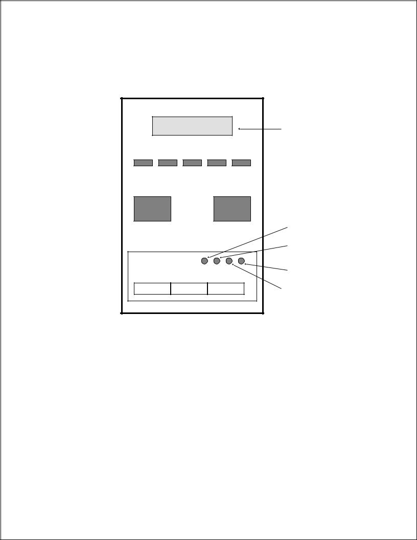
The CL608e/CL612e Operator Panel consists of five LED indicators, two momentary contact switches, three DIP switches, four adjustment potentiometers and one LCD Display. All of these are accessible from the front of the printer. They are used to set the printer operating parameters and to indicate the status of the printer to the operator. After you power on the printer, familiarize yourself with the keys and indicators as it will help you understand the configuration process.
PRINT: |
Potentiometer to adjust print darkness (fine tuning). |
OFFSET: |
Potentiometer to adjust amount of back/forward feed |
|
for dispenser/cutter/tear-off bar position (+/-3.75 mm) |
PITCH: |
Potentiometer to adjust home position of the label |
|
(+/- 3.75 mm). Affects stop position of label feed, print |
|
position and dispense position. |
DISPLAY: |
Potentiometer to adjust the contrast of the LCD. |
POWER: |
LED, illuminated when the power is on. |
Page 2-12 |
PN 9001074 Preliminary |
SATO CL Series “e” Printers |
 Loading...