


Multimedia Projector
MODEL PLC-XF12N/12NL PLC-XF12E/12EL PLC-XF12B/12BL
Owner's Manual
TO THE OWNER
Before operating this projector, read this manual thoroughly and operate the projector properly.
This projector provides many convenient features and functions. Operating the projector properly enables you to manage those features and maintains it in better condition for a considerable time.
Improper operation may result in not only shortening the product-life, but also malfunctions, fire hazard, or other accidents.
If your projector seems to operate improperly, read this manual again, check operations and cable connections and try the solutions in the “Trouble-shooting” section of the end of this booklet. If the problem still persists, contact the sales dealer where you purchased the projector or the service center.
SAFETY PRECAUTIONS
WARNING : TO REDUCE THE RISK OF FIRE OR ELECTRIC SHOCK, DO NOT EXPOSE THIS APPLIANCE TO RAIN OR MOISTURE.
●This projector produces intense light from the projection lens. Do not stare directly into the lens as possible. Eye damage could result. Be especially careful that children do not stare directly into the beam.
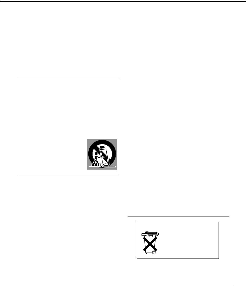
●This projector should be set in the way indicated. If not, it may result in a fire hazard.
● Take appropriate space on the top, sides and rear of the projector |
|
SIDE and TOP |
|
REAR |
|
|||||
cabinet for allowing air circulation and cooling the projector. 20cm |
|
|
|
|
|
|
|
|
|
|
|
|
|
|
|
|
|
|
|
|
|
Minimum distance should be taken. If the projector is to be built |
|
|
|
|
|
|
|
|
|
|
into a compartment or similarly enclosed, the minimum distances |
|
|
|
|
|
|
|
|
||
must be maintained. Do not cover the ventilation slot on the |
|
|
|
|
|
|
|
|
||
|
|
|
|
|
|
|
|
|||
projector. Heat build-up can reduce the service life of your |
|
50cm |
|
50cm |
|
|
1m |
|
||
|
|
|
|
|
||||||
projector, and can also be dangerous. |
|
|
|
|
|
|
|
|
||
●Do not put any flammable object or spray can near the projector, hot air is exhausted from the ventilation holes.
●The Remote Control Unit, supplied to this projector, emits the laser beam as the Laser Pointer function from the Laser Light Window while pressing the LASER button. Do not look into the Laser Light Window or shine the laser beam on yourself or other people. Eye damage may result.
●If the projector is not to be used for an extended time, unplug the projector from the power outlet.
READ AND KEEP THIS OWNER'S MANUAL FOR LATER USE.
CAUTION
RISK OF ELECTRIC SHOCK
DO NOT OPEN
CAUTION : TO REDUCE THE RISK OF ELECTRIC SHOCK, DO NOT REMOVE COVER (OR BACK). NO USERSERVICEABLE PARTS INSIDE EXCEPT LAMP REPLACEMENT. REFER SERVICING TO QUALIFIED SERVICE PERSONNEL.
THIS SYMBOL INDICATES THAT DANGEROUS VOLTAGE CONSTITUTING A RISK OF ELECTRIC SHOCK IS PRESENT WITHIN THIS UNIT.
THIS SYMBOL INDICATES THAT THERE ARE IMPORTANT OPERATING AND MAINTENANCE INSTRUCTIONS IN THE OWNER'S MANUAL WITH THIS UNIT.
2
SAFETY PRECAUTIONS
All the safety and operating instructions should be read before the product is operated.
Read all of the instructions given here and retain them for later use. Unplug this projector from AC power supply before cleaning. Do not use liquid or aerosol cleaners. Use a damp cloth for cleaning.
Follow all warnings and instructions marked on the projector.
For added protection to the projector during a lightning storm, or when it is left unattended and unused for long periods of time, unplug it from the wall outlet. This will prevent damage due to lightning and power line surges.
Do not expose this unit to rain or use near water... for
example, in a wet basement, near a swimming pool, etc...
Do not use attachments not recommended by the manufacturer as they may cause hazards.
Do not place this projector on an unstable cart, stand, or table. The projector may fall, causing serious injury to a child or adult, and serious damage to the projector. Use only with a cart or stand recommended by the manufacturer, or sold with the projector. Wall or shelf mounting should follow the manufacturer's instructions, and should use a mounting kit approved by the manufacturers.
An appliance and cart combination should be moved with care. Quick stops, excessive force, and uneven surfaces may cause the appliance and cart combination to overturn.
Slots and openings in the back and bottom of the cabinet are provided for ventilation, to insure reliable operation of the equipment and to protect it from overheating.
The openings should never be covered with cloth or other materials, and the bottom opening should not be blocked by placing the projector on a bed, sofa, rug, or other similar surface. This projector should never be placed near or over a radiator or heat register.
This projector should not be placed in a built-in installation such as a book case unless proper ventilation is provided.
Never push objects of any kind into this projector through cabinet slots as they may touch dangerous voltage points or short out parts that could result in a fire or electric shock. Never spill liquid of any kind on the projector.
This projector should be operated only from the type of power source indicated on the marking label. If you are not sure of the type of power supplied, consult your authorized dealer or local power company.
Do not overload wall outlets and extension cords as this can result in fire or electric shock. Do not allow anything to rest on the power cord. Do not locate this projector where the cord may be damaged by persons walking on it.
Do not attempt to service this projector yourself as opening or removing covers may expose you to dangerous voltage or other hazards. Refer all servicing to qualified service personnel.
Unplug this projector from wall outlet and refer servicing to qualified service personnel under the following conditions:
a.When the power cord or plug is damaged or frayed.
b.If liquid has been spilled into the projector.
c.If the projector has been exposed to rain or water.
d.If the projector does not operate normally by following the operating instructions. Adjust only those controls that are covered by the operating instructions as improper adjustment of other controls may result in damage and will often require extensive work by a qualified technician to restore the projector to normal operation.
e.If the projector has been dropped or the cabinet has been damaged.
f.When the projector exhibits a distinct change in performance-this indicates a need for service.
When replacement parts are required, be sure the service technician has used replacement parts specified by the manufacturer that have the same characteristics as the original part. Unauthorized substitutions may result in fire, electric shock, or injury to persons.
Upon completion of any service or repairs to this projector, ask the service technician to perform routine safety checks to determine that the projector is in safe operating condition.
Voor de klanten in Nederland
Bij dit product zijn batterijen geleverd.
Wanneer deze leeg zijn, moet u ze niet weggooien maar inleveren als KCA.
3
COMPLIANCES
Federal Communication Commission Notice
This equipment has been tested and found to comply with the limits for a Class A digital device, pursuant to Part 15 of FCC Rules. These limits are designed to provide reasonable protection against harmful interference when the equipment is operated in a commercial environment. This equipment generates, uses, and can radiate radio frequency energy and, if not installed and used in accordance with the instruction manual, may cause harmful interference to radio communications. Operation of this equipment in a residential area is likely to cause harmful interference in which case the user will be required to correct the interference at his own expense.
AC POWER CORD REQUIREMENT
The AC Power Cord supplied with this projector meets the requirement for use in the country you purchased it.
AC Power Cord for the United States and Canada :
AC Power Cord used in the United States and Canada is listed by the Underwriters Laboratories (UL) and certified by the Canadian Standard Association (CSA).
AC Power Cord has a grounding-type AC line plug. This is a safety feature to be sure that the plug will fit into the power outlet. Do not try to defeat this safety feature.
Should you be unable to insert the plug into the outlet, contact your electrician. |
GROUND |
|
AC Power Cord for the United Kingdom :
This cord is already fitted with a moulded plug incorporating a fuse, the value of which is indicated on the pin face of the plug. Should the fuse need to be replaced, an ASTA approved BS 1362 fuse must be used of the same rating, marked thus ASA . If the fuse cover is detachable, never use the plug with the cover omitted. If a replacement fuse cover is required, ensure it is of the same colour as that visible on the pin face of the plug (i.e. red or orange). Fuse covers are available from the Parts Department indicated in your User Instructions. If the plug supplied is not suitable for your socket outlet, it should be cut off and destroyed.
The end of the flexible cord should be suitably prepared and the correct plug fitted. (See Over)
WARNING : A PLUG WITH BARED FLEXIBLE CORD IS HAZARDOUS IF ENGAGED IN A LIVE SOCKET OUTLET.
The Wires in this mains lead are coloured in accordance with the following code: Green-and-yellow ············Earth
Blue ·································Neutral Brown ······························Live
As the colours of the wires in the mains lead of this apparatus may not correspond with the coloured markings identifying the terminals in your plug proceed as follows:
The wire which is coloured green-and-yellow must be connected to the terminal in the plug which is marked by the letter E or by the safety earth symbol  or coloured green or green-and-yellow.
The wire which is coloured blue must be connected to the terminal which is marked with the letter N or coloured black.
The wire which is coloured brown must be connected to the terminal which is marked with the letter L or coloured red.
WARNING : THIS APPARATUS MUST BE EARTHED.
THE SOCKET-OUTLET SHOULD BE INSTALLED NEAR THE EQUIPMENT AND EASILY ACCESSIBLE.
4

TABLE OF CONTENTS
FEATURES AND DESIGN |
6 |
PREPARATION |
7 |
NAME OF EACH PART OF THE PROJECTOR |
7 |
SETTING-UP THE PROJECTOR |
8 |
CONNECTING THE AC POWER CORD |
8 |
POSITIONING THE PROJECTOR |
9 |
PICTURE LEVEL AND TILT ADJUSTMENT |
10 |
MOVING THE PROJECTOR |
10 |
COMPUTER MODE |
36 |
SELECTING COMPUTER MODE |
36 |
SELECTING COMPUTER SYSTEM |
36 |
COMPATIBLE COMPUTER SPECIFICATIONS |
37 |
PC ADJUSTMENT |
38 |
PICTURE IMAGE ADJUSTMENT |
40 |
NORMAL FUNCTION |
41 |
AUTO IMAGE ADJUSTMENT |
41 |
PICTURE POSITION ADJUSTMENT |
42 |
PICTURE SCREEN ADJUSTMENT |
43 |
CONNECTING THE PROJECTOR
TERMINAL OF THE PROJECTOR CONNECTING THE COMPUTER CONNECTING THE VIDEO EQUIPMENT
BEFORE OPERATION
CONTROLS AND INDICATORS OPERATION OF THE REMOTE CONTROL
WIRELESS REMOTE CONTROL UNIT WIRELESS/WIRED REMOTE CONTROL UNIT
OPERATING ON-SCREEN MENU
HOW TO OPERATE ON-SCREEN MENU FLOW OF ON-SCREEN MENU
MENU BAR
BASIC OPERATION
TURNING ON / OFF THE PROJECTOR
TO TURN ON THE PROJECTOR
TO TURN OFF THE PROJECTOR
ADJUSTING THE IMAGE
ZOOM ADJUSTMENT
FOCUS ADJUSTMENT
LENS SHIFT FUNCTION DIGITAL ZOOM FUNCTION NORMAL PICTURE FUNCTION FREEZE PICTURE FUNCTION NO SHOW FUNCTION P-TIMER FUNCTION
AUTO IMAGE ADJUSTMENT CURSOR FUNCTION
11 |
VIDEO MODE |
44 |
11 |
SELECTING VIDEO MODE |
44 |
13 |
SELECTING VIDEO SOURCE |
44 |
21 |
SELECTING COLOR SYSTEM |
45 |
|
PICTURE IMAGE ADJUSTMENT |
46 |
23 |
NORMAL FUNCTION |
47 |
PICTURE SCREEN ADJUSTMENT |
47 |
23 |
SETTING |
48 |
|
25 |
|
|
|
25 |
SETTING MENU |
48 |
|
28 |
SETTING LANGUAGE |
49 |
|
30 |
|||
|
|
||
30 |
|
|
|
30 |
APPENDIX |
50 |
|
31 |
|||
|
|
||
32 |
|
|
|
32 |
AIR FILTER CARE AND CLEANING |
51 |
|
32 |
|||
LAMP REPLACEMENT |
52 |
||
32 |
|||
CLEANING THE PROJECTION LENS |
53 |
||
33 |
|||
TROUBLESHOOTING |
53 |
||
33 |
|||
TECHNICAL SPECIFICATIONS |
55 |
||
33 |
|||
|
|
||
33 |
|
|
|
33 |
|
|
|
33 |
|
|
|
34 |
|
|
|
34 |
|
|
|
34 |
|
|
|
34 |
|
|
|
34 |
|
|
SOUND ADJUSTMENT |
35 |
DIRECT OPERATION |
35 |
MENU OPERATION |
35 |
TRADEMARKS
●Apple, Macintosh, and PowerBook are trademarks or registered trademarks of Apple Computer,Inc.
●IBM and PS/2 are trademarks or registered trademarks of International Business Machines, Inc.
●Windows and PowerPoint are registered trademarks of Microsoft Corporation.
●Each name of corporations or products in the owner's manual is a trademark or a registered trademark of its respective corporation.
5

FEATURES AND DESIGN
This Multimedia Projector is designed with the most advanced technology for portability, durability, and ease of use. The projector utilizes built-in multimedia features, a palette of 16.77 million colors, and matrix liquid crystal display (LCD) technology.
Compatibility
This projector widely accepts various video and computer input signals including;
●Computers
IBM-compatible and Macintosh computers up to 1280 x 1024 resolution.
●6 Color Systems
NTSC, PAL, SECAM, NTSC 4.43, PAL-M or PAL- N color system can be connected.
●S-Video
S-Video signals, such as a S-VHS VCR output signals, can be connected.
High Resolution Image
This projector provides 1024 x 768 dots resolution for computer input and 800 horizontal TV lines. The resolution from the computer between 1024 x 768 and 1280 x 1024 is compressed into 1024 x 768 dots. This projector cannot display image of over 1280 x 1024 dots. When the resolution of your computer is over than 1280 x 1024, reset the computer output for lower resolution.
Power Management
Power Management function is provided to reduce power consumption while the projector is not in use.
This Power Management function operates to turn the Projection Lamp off when the projector detects signal interruption and any button is not pressed over 5 minutes. The Projection Lamp is automatically turned on again when the projector detects the signal or any operation button is pressed.
This projector is shipped with this function ON.
Laser Pointer Function
The Wireless Remote Control Unit supplied with this projector includes the Laser Pointer function. This function helps you to make a smart presentation on a projected screen.
Wireless Mouse
The Wireless Remote Control Unit supplied with this projector has Wireless Mouse function for the connected computer. This function enables you to operate both projector and computer with this Wireless Remote Control Unit only.
Multi-Scan System |
|
|
|
|
|
|
Accessories |
||
|
|
|
|
|
This projector has Multi-Scan System to conform to almost all computer output signals quickly. There is no need for troublesome manual adjustment of frequency and other settings.
One-Touch Auto Imaging
Incoming computer video signals are recognized and the best setting is automatically selected by the Auto Image adjustment. No complicated setup is necessary and projection is always precise.
Multilanguage Menu Display
Operation menu is displayed in; English, Deutsch, Français, Italiano, Español, or Japanese.
Digital Zoom (Computer Mode only)
The Digital Zoom magnifies the image up to 16 times, allowing you to focus on crucial information at a presentation.
The projector comes with the parts listed below. Check to find all the parts are included. If any parts are missing, contact an authorized dealer or service station.
●Owner's Manual.
●AC Power Cord.
●Wireless Remote Control Unit.
●Wireless/Wired Remote Control Unit.
●Remote Control Cable.
●Batteries for Remote Control Units.
●VGA Cable.
●Mouse Cable for PS/2 port.
●Mouse Cable for serial port.
●Mouse Cable for ADB port.
●VGA/MAC Adapter.
●Protective Dust Cover
●Lens Cover.
Motor-driven Lens Shift
The projection lens can be moved up and down with the motor-driven lens shift function. This function makes it easy to provide the projected image where you want.
The zoom and focus can be also adjusted with motordriven operation.
6
PREPARATION
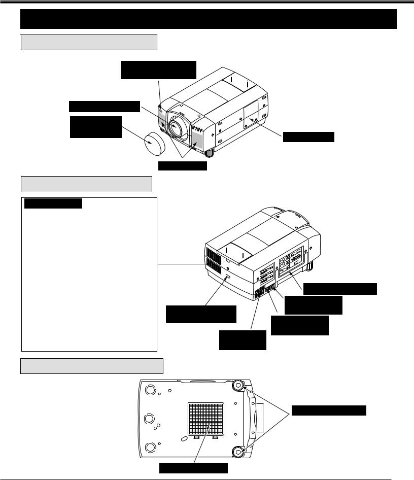
NAME OF EACH PART OF THE PROJECTOR
FRONT OF THE PROJECTOR
INFRARED
REMOTE RECEIVER
PROJECTION LENS
REMOVABLE
LENS COVER
SPEAKERS
REAR OF THE PROJECTOR
EXHAUST VENT
 HOT AIR EXHAUSTED !
Air blown from the exhaust vent is hot. Observe the following when handling your projector or choosing a location to install it.
●Keep heat-sensitive objects away from the exhaust port.
●If you set the projector on top of a metallic surface, the surface will become hot because of the hot air exhaust. Be careful when handling.
●Do not touch the cabinet near to the exhaust vent area, and especially screws and metallic parts. These parts will become hot while the projector is used.
This projector detects the internal temperature and automatically controls the operating power of the Cooling Fans.
INFRARED
REMOTE RECEIVER
AIR INTAKE
VENT
BOTTOM OF THE PROJECTOR
LAMP COVER
CARRYING HANDLE
MAIN ON / OFF
SWITCH
POWER CORD
CONNECTOR
ADJUSTABLE FEET
AIR INTAKE VENT
7
PREPARATION
SETTING-UP THE PROJECTOR
CONNECTING THE AC POWER CORD
This projector uses nominal input voltages of 100-120 V or 200-240 V AC. The projector automatically selects the correct input voltage. It is designed to work with single-phase power systems having a grounded neutral conductor. To reduce the risk of electrical shock, do not plug into any other type of power system.
Consult your authorized dealer or service station if you are not sure of the type of power supply being in use.
Connect the projector with the peripheral equipment before turning the projector on. (Refer to pages 13 ~ 22 for connection.)
Connect the AC Power Cord (supplied) to the projector.
The AC outlet must be near this equipment and must be easily accessible.
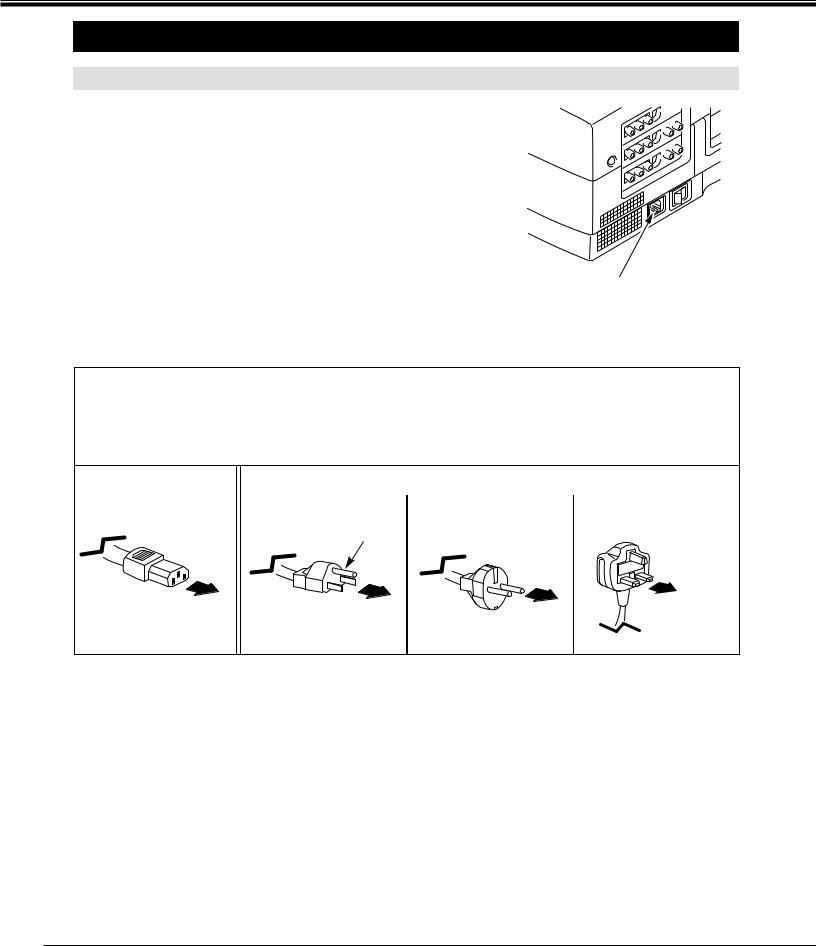
NOTE ON THE POWER CORD
The AC Power Cord must meet the requirement of the country where you use the projector. Confirm the AC plug type with the chart below and the proper AC power cord must be used. If the supplied AC Power Cord does not match the AC outlet, contact your sales dealer.
Projector side |
|
|
|
|
|
AC Outlet side |
|
|
|
|
|
|
|
|
|
|
|
|
|
|
|
|
|
|
|
|
|
||
|
For the U.S.A. and Canada |
For Continental Europe |
For the U.K. |
||||||
|
|
|
|
|
|
|
|
|
|
|
|
|
|
|
|
|
|
|
|
|
|
|
Ground |
|
|
|
|
||
To the POWER CORD |
|
|
|
|
|
To the AC Outlet. |
|
To the AC Outlet. |
|
|
|||
CONNECTOR on the |
|
|
|
|
(200 - 240 V AC) |
|
|
(120 V AC) |
|
To the AC Outlet. |
|
||
projector. |
|
|
|
(200 - 240 V AC) |
|
|
|
|
|
|
|
||
|
|
|
|
|||
|
|
|
|
|
|
|
|
|
|
|
|
|
|
8
PREPARATION
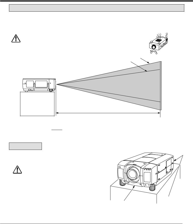
POSITIONING THE PROJECTOR
●This projector is basically designed to project on a flat projection surface.
●This projector can be focused from 4.9' (1.5 m) ~ 80.7' (24.6 m).
●Refer to the figure below as an example when positioning the projector to the screen.
THIS PROJECTOR SHOULD BE SET IN THE WAY INDICATED. NEVER HANG
THE PROJECTOR, OR FALL DOWN ON ITS SIDE. IT MAY RESULT IN FIRE
HAZARD.
ROOM LIGHT |
|
|
|
|
|
|
|
|
|
|
Maximum Zoom |
600" |
|||||||
|
|
|
|
|
|
|
|
|
|
|
|
|
Minimum Zoom |
||||||
The projector should be placed in a room with |
|
|
|
|
|
|
|
|
|||||||||||
|
|
|
|
|
|
|
|
|
|
||||||||||
|
|
|
|
|
|
|
|
400" |
|
|
|||||||||
limited light. Picture quality will be directly |
|
|
|
|
|
|
|
|
|
|
|||||||||
|
|
|
|
|
|
|
|
300" |
|
|
|
|
|||||||
affected by lightning conditions. |
|
|
150" |
200" |
|
|
462" |
|
|||||||||||
|
|
|
|
|
|
|
|
||||||||||||
|
|
|
|
|
|
|
|
||||||||||||
100" |
|
|
|
|
|
|
|
|
|
||||||||||
|
|
|
|
|
|
|
|
308" |
|
|
|
|
|||||||
40" |
|
115" |
|
154" |
|
|
231" |
|
|
|
|
|
|||||||
|
|
|
|
|
|
|
|
|
|
||||||||||
|
|
|
|
|
|
|
|
|
|
|
|
|
|
|
|||||
|
|
|
|
77" |
|
|
|
|
|
|
|
|
|
|
|
||||
|
|
|
|
|
|
|
|
|
|
|
|
|
|
|
|
|
|
|
|
|
|
|
|
|
|
|
|
|
|
|
|
|
|
|
|
|
|
|
|
|
|
|
|
|
|
|
|
|
|
|
|
|
|
|
|
|
|
|
|
|
|
|
|
|
|
|
|
|
|
|
|
|
|
|
|
|
|
|
|
|
|
|
|
|
|
|
|
|
|
|
|
|
|
|
|
|
|
|
|
|
|
|
|
|
|
|
|
|
|
|
|
|
|
|
|
|
|
|
|
|
|
|
|
|
|
|
|
|
|
|
|
|
|
|
|
|
|
|
|
|
|
|
|
|
|
|
|
|
|
|
|
|
|
|
|
|
|
|
|
|
|
|
|
|
|
|
|
|
|
|
|
|
|
|
|
|
|
|
|
DISTANCE
Screen |
Max. Zoom |
40" |
100" |
150" |
200" |
300" |
400" |
600" |
|
Size |
Min. Zoom |
|
77" |
115" |
154" |
231" |
308" |
462" |
|
|
|
|
|
|
|
|
|
|
|
Distance |
4.9' (1.5 m) |
13.1' (4.0 m) |
20' (6.1 m) |
26.9' (8.2 m) |
40' (12.2 m) |
53.8' (16.4 m) |
80.7' (24.6 m) |
|
|
|
|
|
|
|
|
|
|
|
|
VENTILATION
This projector is equipped with a cooling fan to protect it from overheating. Pay attention to the following to ensure the ventilation and avoid a possible risk of fire and malfunction.
● Do not cover the vents with papers or other materials.
● Keep the rear grill at least 3.3' (1m) away from any object.
● Make sure that there are no objects under the projector. An object under the projector may prevent the projector from taking the cooling air through the bottom vent.
EXHAUST VENT AIR INTAKE VENT (REAR SIDE) (BOTTOM SIDE)
9
PREPARATION
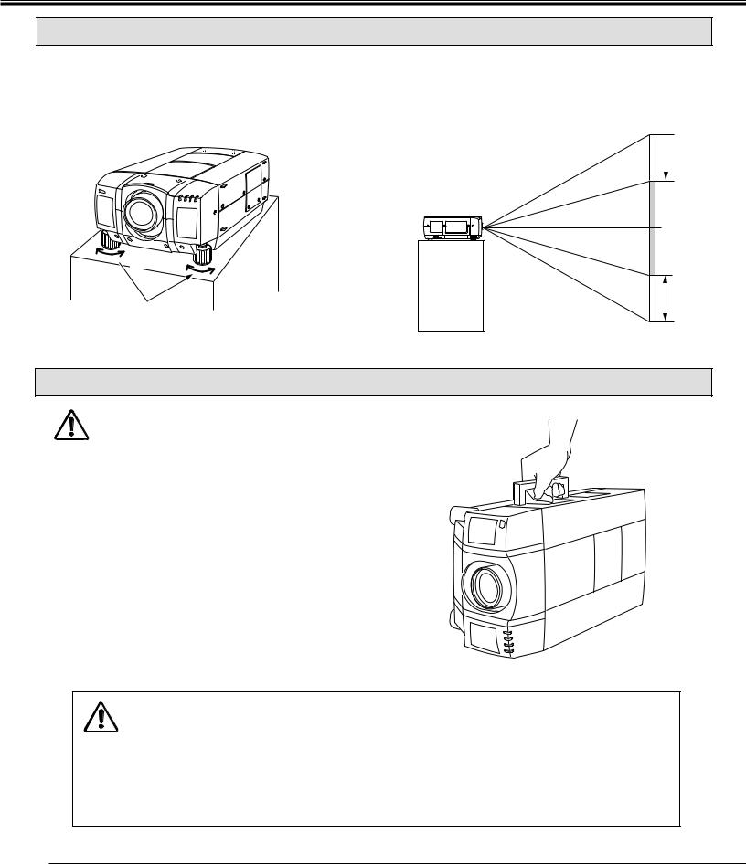
PICTURE LEVEL AND TILT ADJUSTMENT
Picture tilt and projection angle can be adjusted by twisting ADJUSTABLE FEET. Projection angle can be adjusted up to 4 degrees by rotating Adjustable Feet.
 DOWN
DOWN
UP |
DOWN |
UP
ADJUSTABLE FEET
MOVE THE PROJECTED IMAGE POSITION
Adjust the projected image position (maximum 760mm downward or upward on the 100" screen) by using lens shift function. (See page 33.)
 760 mm
100" SCREEN
760 mm
MOVING THE PROJECTOR
Use the carry handle when moving the projector.
Replace the lens cover and rotate the adjustable feet fully clockwise.
CAUTION IN CARRYING OR TRANSPORTING THE PROJECTOR
●Do not drop or bump the projector, otherwise damages or malfunctions may result.
●When carrying the projector, use a suitable carrying case.
●Do not transport the projector by using a courier or transport service in an unsuitable transport case. This may cause damage to the projector. To transport the projector through a courier or transport service, consult your dealer and best case should be applied.
10
CONNECTING THE PROJECTOR
TERMINAL OF THE PROJECTOR
SIDE OF THE PROJECTOR (CONNECT THE COMPUTER)
|
9 |
8 |
6 |
5 |
1 |
|
|
2 |
|
10 |
USB 1 CONTROL PORT 1 |
AUDIO 1 |
ANALOG |
|
|
DIGITAL |
|
||
|
|
|
R L (MONO) |
|
|
|
|||
11 |
USB 2 CONTROL PORT 2 |
AUDIO 2 |
|
G |
B |
H |
V |
||
|
|
|
R |
|
|||||
|
|
|
(MONO) |
|
|
|
|
|
|
R/C JACK SERIAL PORT |
AUDIO OUT |
ANALOG RGB |
||
R |
L |
|||
|
||||
|
|
|||
COMPUTER OUT COMPUTER IN-2 COMPUTER IN-1
3
4
1
2
3
4
5
13 12 7
|
8 |
CONNECTOR |
|
|
|
cable to the projector. |
|
COMPUTER INPUT-1 TERMINAL (DIGITAL MDR 20-PIN) |
9 |
CONTROL PORT-2 CONNECTOR |
|
Used to connect a computer to the projector. |
|
Used to connect a mouse cable to the projector. |
|
COMPUTER INPUT-2 JACKS (BNC TYPE x 5) |
10 |
USB PORT-1 CONNECTOR |
|
Used to connect a computer to the projector. |
|
Used to connect a computer to the projector. |
|
MONITOR OUTPUT TERMINAL (ANALOG HDB 15-PIN) |
11 |
USB PORT-2 CONNECTOR |
|
Used to connect a monitor to the projector. |
|
Used to connect a computer to the projector. |
|
COMPUTER AUDIO INPUT-1 JACKS (R and L) |
12 |
SERIAL PORT TERMINAL (DB9) |
|
Used to connect an audio output from the computer to the |
|
Used to connect a computer to the projector. |
|
projector. |
13 |
WIRED REMOTE JACK |
|
COMPUTER AUDIO INPUT-2 JACKS (R and L) |
|||
|
When using the wired remote control, connect the |
||
Used to connect an audio output from the computer to the |
|
remote cable to this jack. |
|
projector. |
|
|
7
Used to connect an audio input from audio equipment to the projector.
11
CONNECTING THE PROJECTOR
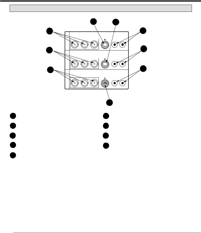
SIDE OF THE PROJECTOR (CONNECT THE VIDEO EQUIPMENT)
14
17
20
MONITOR OUT VIDEO IN-2 VIDEO IN-1
15 18
16
VIDEO/Y C/Cb(B-Y) Cr(R-Y) |
S-VIDEO |
AUDIO |
||||||
|
|
|
|
|
|
|
R |
L (MONO) |
|
||||||||
|
|
|
|
|
|
|
|
|
|
|
|
|
|
|
|
|
|
19
VIDEO/Y C/Cb(B-Y) Cr(R-Y) |
S-VIDEO |
AUDIO |
||||||
|
|
|
|
|
|
|
R |
L (MONO) |
|
||||||||
|
|
|
|
|
|
|
|
|
|
|
|
|
|
|
|
|
|
22
VIDEO/Y C/Cb(B-Y) Cr(R-Y) |
S-VIDEO |
AUDIO |
R L
14
15 S-VIDEO INPUT JACK-1
Used to connect a S-VHS video source to the projector.
16 AUDIO INPUT JACKS-1 (R and L)
Used to connect an audio source to the projector.
17 VIDEO INPUT JACKS-2 (BNC TYPE x 3)
Used to connect a video source to the projector.
18 S-VIDEO INPUT JACK-2
Used to connect a S-VHS video source to the projector.
21
19
|
projector. |
20 |
VIDEO MONITOR OUTPUT JACKS (BNC TYPE x 3) |
|
Permits video connection to a monitor. |
21 |
VIDEO MONITOR (S-VIDEO) OUTPUT JACK |
|
Permits S-VHS video connection to a monitor. |
22 |
AUDIO MONITOR OUTPUT JACKS (R and L) |
|
Permits audio connection to a monitor. |
12
CONNECTING THE PROJECTOR
CONNECTING THE COMPUTER
CONNECTING TO THE COMPUTER INPUT 1 TERMINAL (ANALOG HDB 15-PIN)
Personal computers can be connected to the HDB15-pin (VGA) terminal on the projector.
● Connect the computer to these terminals using the VGA cable and VGA/MAC adapter (provided).
CAUTION: For projectors, the VGA cable provided is designed to reduce RFI (Radio Frequency Interference) emissions. For regulatory compliance reasons, this cable must be used and must not be replaced by any other cable.
CONNECTING TO THE COMPUTER INPUT 1 TERMINAL (DIGITAL MDR 20-PIN)
Digital output signal from the computer can be connected to the DIGITAL terminal (MDR 20-pin). When using this input, Graphic Accelerator Board designed for this projector should be installed into your computer and set-up the computer configuration following instruction included in the Graphic Accelerator Board package. Refer to DIGITAL INPUT CONNECTION on page 16 and 18.
CONNECTING TO THE COMPUTER INPUT 2 JACKS (BNC x 5)
Personal computers can be connected to the computer input (Red, Green, Blue, Horiz. Sync. and Vert. Sync.) on the projector.
● Connect the computer to these jacks using the BNC cables (not provided).
CONNECTING TO THE COMPUTER AUDIO INPUT JACKS (1 and 2)
● Connect audio outputs from your computer to these jacks using the audio cable (not provided).
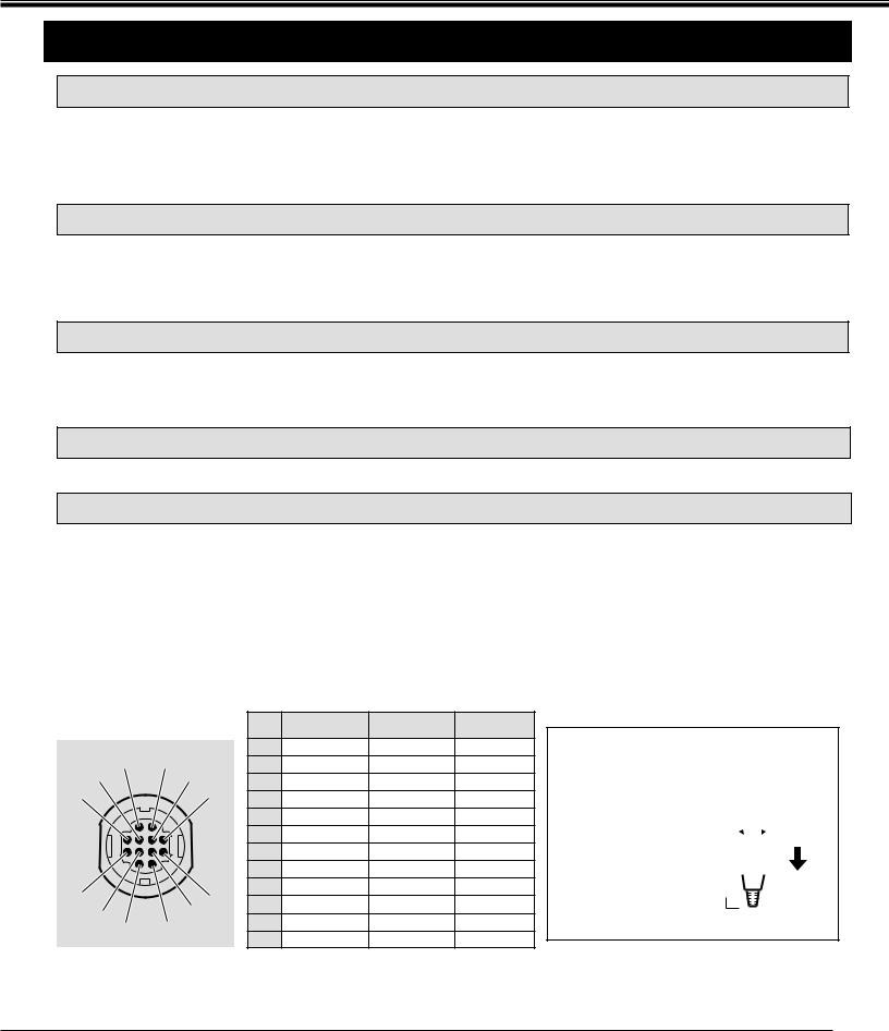
CONNECTING TO THE MULTI-POLE 12-PIN (CONTROL PORT) CONNECTORS (1 and 2)
●When the computer is operated by projector's remote control unit, connect three different type of cables (provided) between projector control port and computer mouse port or serial port.
COMPUTER TYPE |
CABLE |
IBM Compatible computer with PS/2 mouse port. |
Mouse Cable for PS/2 port. |
|
|
IBM Compatible computer with serial port. |
Mouse Cable for Serial port. |
|
|
Apple Macintosh computer with ADB mouse port. |
Mouse Cable for ADB port. |
|
|
■ CONTROL PORT |
|
PS/2 Port |
Serial Port |
ADB Port |
|||
|
|
|
|
|
|||
|
2 |
1 |
|
1 |
–––––––– |
T x D |
–––––––– |
5 |
|
2 |
CLK |
–––––––– |
ADB |
||
|
4 |
|
3 |
DATA |
–––––––– |
–––––––– |
|
6 |
|
|
3 |
||||
|
|
4 |
–––––––– |
–––––––– |
–––––––– |
||
|
|
|
|
||||
|
|
|
|
5 |
–––––––– |
–––––––– |
–––––––– |
|
|
|
|
6 |
–––––––– |
–––––––– |
–––––––– |
|
|
|
|
7 |
–––––––– |
READY |
–––––––– |
|
|
|
|
8 |
–––––––– |
–––––––– |
–––––––– |
10 |
|
|
7 |
9 |
GND |
GND |
GND |
|
8 |
10 |
–––––––– |
–––––––– |
–––––––– |
||
9 |
|
||||||
12 |
|
11 |
–––––––– |
–––––––– |
–––––––– |
||
|
11 |
|
12 |
–––––––– |
–––––––– |
–––––––– |
|
CONTROL PORT CABLE REMOVAL HINT
Disconnect control port cable with following steps.
1. |
Hold the portion (A) |
|
|
|
|
|
|
|||
|
|
|
|
|
|
|||||
|
of the connector |
|
|
|
|
|
|
|||
|
|
|
|
|
B |
|||||
|
with one hand. |
|
|
|
|
|||||
|
|
|
|
|||||||
|
|
|
|
|||||||
|
|
|
|
|
|
|
||||
2. |
Pull the portion (B) |
|
|
|
|
|
|
|
|
|
|
|
|
|
|
|
|
|
|
||
A
arrow direction and remove connector.
13
CONNECTING THE PROJECTOR
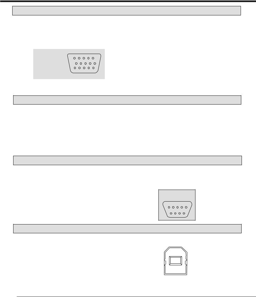
CONNECTING TO THE MONITOR OUTPUT TERMINAL (ANALOG HDB 15-PIN)
This terminal output the information of the selected computer source being viewed on the screen (Computer 1 or Computer 2). When video source ("Video 1" or "Video 2") is selected, this terminal outputs Computer 1 input information.
An external monitor can be connected to the HDB15-pin (VGA) terminal on the projector.
● Connect the monitor to this terminal using the VGA cable (not provided).
|
5 |
4 |
3 |
2 |
1 |
HDB 15-PIN |
10 |
9 |
8 |
7 |
6 |
TERMINAL |
|
|
|
|
|
|
15 14 13 12 11 |
||||
Pin No./Signal |
Pin No./Signal |
||
1 |
Red input |
9 |
Non Connect |
2 |
Green input |
10 |
Ground (Vert. sync.) |
3 |
Blue input |
11 |
Sense 0 |
4 |
Sense 2 |
12 |
Sense 1 |
5 |
Ground (Horiz.sync.) |
13 |
Horiz. sync |
6 |
Ground (Red) |
14 |
Vert. sync |
7 |
Ground (Green) |
15 |
Reserved |
8 |
Ground (Blue) |
|
|
CONNECTING TO THE AUDIO MONITOR OUTPUT (VARIABLE) JACKS
These jacks will contain the audio information of the selected program source being viewed on the screen (Computer 1, Computer 2, Video 1 or Video 2). If you have selected program source Computer 2 the audio signal connected to the Computer 2 audio input jack will be available at the audio monitor output jacks.
Use RCA type audio for connection.
●If the audio input of the audio equipment is stereo, be sure to connect the right and left channels to the respective right and left jacks.
●If the audio input of the audio equipment is monaural, connect it to the left jack.
CONNECTING TO THE SERIAL PORT (DB 9-PIN) TERMINAL
●If you control the projector by computer, you must connect a cable (not provided) from your computer to this terminal.
■ SERIAL PORT
DB9-PIN |
|
|
|||
TERMINAL |
|||||
5 |
4 |
|
3 |
2 |
1 |
|
9 |
8 |
7 |
|
6 |
1 |
–––––––– |
2 |
R x D |
3 |
T x D |
4 |
–––––––– |
5 |
Ground |
6 |
–––––––– |
7 |
–––––––– |
8 |
–––––––– |
9 |
–––––––– |
CONNECTING TO THE USB PORT CONNECTORS (1 and 2)
This port is used to control the projector with the computer. It is also used to control the computer with the Remote control of this projector. (Refer to P49, 50.)
Connect the USB port of the computer to this port.
■ USB PORT
|
|
|
|
|
|
|
|
|
2 |
|
1 |
|
|
1 |
Vcc |
|
|
|
|
|
|
||
|
3 |
|
4 |
|
|
2 |
- Data |
|
|
|
|
3 |
+ Data |
||
|
|
|
|
|
|
||
|
|
|
|
|
|
4 |
Ground |
14

CONNECTING THE PROJECTOR
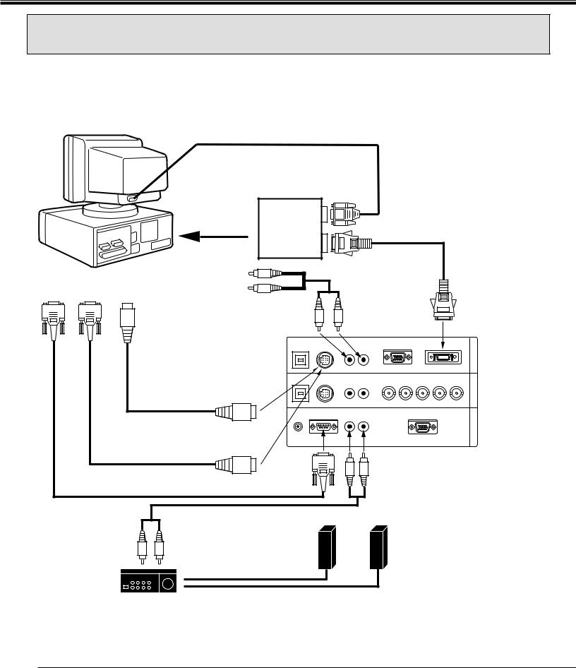
CONNECTING AN IBM-COMPATIBLE DESKTOP COMPUTER
MONITOR CABLE
(NOT PROVIDED)
COMPUTER
COMPUTER |
BNC CABLE x 5 |
(NOT PROVIDED) |
|
OUTPUT |
|
(BNC TYPE x 5) |
|
|
|
|
|
VGA CABLE |
|
|
|
COMPUTER OUTPUT |
(PROVIDED) |
|
|
|
|
|
|
||
|
|
(HDB15-PIN TYPE) |
|
|
|
|
|
|
AUDIO CABLE |
|
|
|
|
|
(NOT PROVIDED) |
|
|
SERIAL PORT |
PS/2 PORT |
COMPUTER |
R |
|
|
|
|
|
|||
AUDIO OUTPUT |
L |
|
|
||
INPUT |
INPUT |
|
|
||
|
|
|
|
||
|
|
|
|
|
COMPUTER |
|
|
COMPUTER |
|
INPUT 1 |
|
|
|
|
(ANALOG) |
||
|
|
AUDIO INPUT 1 or 2 R |
L |
||
|
|
|
|||
|
|
|
USB 1 |
CONTROL PORT 1 |
AUDIO 1 |
|
ANALOG |
|
DIGITAL |
|
IN-1 |
|
|
|
|
|
|
|
R |
|
(MONO) |
|
|
|
|
COMPUTER |
|
|
|
|
|
|
|
|
|
|
|
|
|
|
|
MOUSE CABLE FOR |
USB 2 |
CONTROL PORT 2 |
AUDIO 2 |
R |
G |
B |
H |
V |
IN-2 |
COMPUTER |
|||
|
|
|
|
COMPUTER |
|||||||||
PS/2 PORT |
|
|
|
|
|
(MONO) |
|
|
|
|
|||
|
|
|
|
|
|
|
|
|
|
||||
|
|
|
|
|
|
|
|
|
|
INPUT 2 |
|||
(PROVIDED) |
|
|
|
|
|
|
|
|
|
|
|||
|
|
|
|
|
|
|
|
|
|
|
|||
|
|
|
|
|
|
|
|
|
|
|
|
|
|
|
|
|
R/C JACK |
SERIAL PORT |
AUDIO OUT |
|
ANALOG RGB |
|
|
OUT |
MONITOR |
||
|
|
|
R |
L |
|
|
|
|
|||||
|
|
|
|
|
|
|
|
|
|
COMPUTER |
|||
|
|
|
|
|
|
|
|
|
|
|
|
||
MOUSE CABLE FOR |
CONTROL PORT |
|
|
|
|
|
|
|
|
|
OUTPUT |
||
OUTPUT 1 or 2 |
|
|
|
|
|
|
|
|
|
|
|||
SERIAL PORT |
|
|
|
|
|
|
|
|
|
|
|
|
|
(PROVIDED) |
|
|
|
|
|
|
|
|
|
|
|
|
|
|
|
|
SERIAL |
|
|
|
|
|
|
|
|
|
|
SERIAL PORT CABLE |
|
|
PORT |
|
|
|
|
|
|
|
|
|
|
(NOT PROVIDED) |
|
|
OUTPUT |
|
|
|
|
|
|
|
|
|
|
|
AUDIO CABLE |
|
|
|
|
COMPUTER |
|
|
|
|
|
||
|
|
|
|
|
AUDIO OUTPUT |
|
|
|
|
||||
|
(NOT PROVIDED) |
|
|
|
|
|
|
|
|
|
|
|
|
AUDIO |
|
SPEAKER |
|
|
|
|
|
|
|
|
|
|
|
INPUT |
|
|
|
|
|
|
|
|
|
|
|
|
|
|
|
OUT |
|
|
|
|
|
|
|
|
|
|
|
L |
R |
L |
Speaker (L) |
|
|
|
|
Speaker (R) |
|
|
|
|
|
|
|
|
|
|
|
|
|
|
|
||||
|
|
|
|
|
|
|
|
|
|
|
|
|
|
Amp. |
|
R |
|
|
|
|
|
|
|
|
|
|
|
|
|
|
|
|
|
|
|
|
|
|
|
|
|
NOTE: When connecting the cable, the power cords of both the projector and the external equipment should be disconnected from AC outlet. Turn the projector and peripheral equipment on before the computer is switched on.
15
CONNECTING THE PROJECTOR
CONNECTING AN IBM-COMPATIBLE DESKTOP COMPUTER
(DIGITAL INPUT CONNECTION)
NOTE: This connection need optionally sold Graphic Accelerator Board. For this information, contact to your authorized dealer.
Before using with digital connection, install (Plug in) Graphic Accelerator
Board into PCI bus slot of the computer and set up the computer
COMPUTER |
following instructions in the Graphic Accelerator Board package. |
|||||
|
|
|||||
|
|
|
|
MONITOR CABLE |
|
|
|
|
|
|
(NOT PROVIDED) |
|
|
|
|
GRAPHIC |
|
ANALOG |
|
|
|
|
ACCELERATOR |
|
DIGITAL FLAT |
||
|
|
BOARD |
|
OUTPUT |
|
|
|
|
|
|
PANEL CABLE |
||
|
|
|
|
|
|
|
|
|
|
|
DIGITAL |
|
(NOT PROVIDED) |
|
|
|
|
|
|
|
|
|
INSTALL (PLUG) |
|
OUTPUT |
|
|
|
|
INTO PCI BUS SLOT |
|
|
|
|
SERIAL PORT |
PS/2 PORT |
COMPUTER |
R |
|
AUDIO CABLE |
|
|
|
|||||
AUDIO OUTPUT |
L |
|
(NOT PROVIDED) |
|||
INPUT |
INPUT |
|
||||
|
|
|
|
|
||
|
|
|
|
|
|
COMPUTER |
|
|
|
COMPUTER |
|
|
INPUT 1 |
|
|
|
AUDIO INPUT 1 R |
L |
(DIGITAL) |
|
|
|
USB 1 |
CONTROL PORT 1 |
AUDIO 1 |
|
ANALOG |
|
DIGITAL |
|
IN-1 |
|
|
|
|
|
R |
|
(MONO) |
|
|
|
|
COMPUTER |
|
|
|
|
|
|
|
|
|
|
|
|
MOUSE CABLE FOR |
USB 2 |
CONTROL PORT 2 |
AUDIO 2 |
R |
G |
B |
H |
V |
IN-2 |
||
PS/2 PORT |
|
|
R |
L |
(MONO) |
|
|
|
|
COMPUTER |
|
|
|
|
|
|
|
|
|
|
|||
(PROVIDED) |
|
|
|
|
|
|
|
|
|
||
|
|
|
|
|
|
|
|
|
|
|
|
|
|
R/C JACK |
SERIAL PORT |
AUDIO OUT |
|
ANALOG RGB |
|
|
OUT |
||
|
|
R |
L |
|
|
|
|
||||
|
|
|
|
|
|
|
|
|
COMPUTER |
||
MOUSE CABLE FOR |
CONTROL PORT |
|
|
|
|
|
|
|
|
|
|
SERIAL PORT |
OUTPUT 1 |
|
|
|
|
|
|
|
|
|
|
|
|
|
|
|
|
|
|
|
|
||
(PROVIDED) |
|
|
|
|
|
|
|
|
|
|
|
SERIAL PORT CABLE |
|
SERIAL |
|
|
|
|
|
|
|
|
|
|
PORT |
|
|
|
|
|
|
|
|
|
|
(NOT PROVIDED) |
|
OUTPUT |
|
|
|
|
|
|
|
|
|
|
|
|
|
|
COMPUTER |
|
|
|
|
||
|
AUDIO CABLE |
|
|
|
AUDIO OUTPUT |
|
|
|
|||
|
|
|
|
|
|
|
|
|
|
|
|
|
(NOT PROVIDED) |
|
|
|
|
|
|
|
|
|
|
AUDIO
INPUT |
|
SPEAKER |
|
|
L |
R |
OUT |
|
|
|
Speaker (L) |
Speaker (R) |
||
|
|
L |
||
|
|
|
|
R
Amp.
NOTE: When connecting the cable, the power cords of both the projector and the external equipment should be disconnected from AC outlet. Turn the projector and peripheral equipment on before the computer is switched on.
16
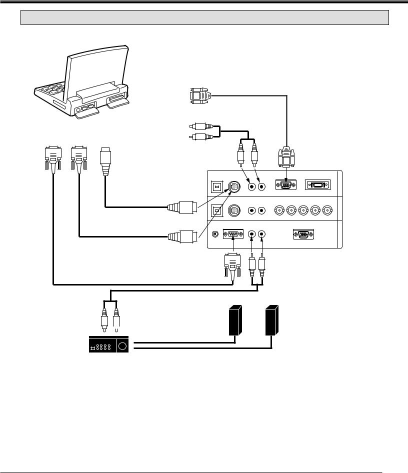
CONNECTING THE PROJECTOR
CONNECTING AN IBM-COMPATIBLE LAPTOP COMPUTER
COMPUTER
|
|
|
|
|
|
VGA CABLE |
|
|
|
COMPUTER OUTPUT |
|
|
(PROVIDED) |
|
|
|
|
|
|
|
|
||
|
|
(DB15-PIN TYPE) |
|
|
|
|
|
|
|
|
R |
AUDIO CABLE |
|
||
|
|
COMPUTER |
|
(NOT PROVIDED) |
|
||
SERIAL PORT |
PS/2 PORT |
|
|
|
|
|
|
AUDIO OUTPUT |
|
|
|
|
|
||
INPUT |
INPUT |
|
|
|
|
|
|
|
|
|
|
|
|
||
|
|
|
L |
|
|
|
|
|
|
|
COMPUTER |
|
|
|
COMPUTER |
|
|
|
|
|
|
INPUT 1 |
|
|
|
|
AUDIO INPUT 1 |
R |
|
L |
|
|
|
|
|
(ANALOG) |
|||
|
|
|
|
|
|
|
|
|
|
|
USB 1 |
CONTROL PORT 1 |
|
ANALOG |
DIGITAL |
|
|
|
|
|
R |
(MONO) |
|
|
MOUSE CABLE FOR |
|
|
|
|
|
|
|
PS/2 PORT |
|
|
|
|
|
|
|
(PROVIDED) |
USB 2 |
CONTROL PORT 2 AUDIO 2 |
|
|||
|
|
|
B H V |
||||
|
|
|
|
|
R |
R G |
|
|
|
|
|
|
L (MONO) |
|
|
|
|
CONTROL PORT |
|
|
|
|
|
|
|
OUTPUT 1 |
R/C JACK |
SERIAL PORT |
AUDIO OUT |
ANALOG RGB |
|
|
|
|
R |
L |
|||
|
|
|
|
|
|
||
MOUSE CABLE FOR |
|
|
|
|
|
||
SERIAL PORT |
|
|
|
|
|
|
|
(PROVIDED) |
|
SERIAL |
|
|
|
|
|
|
|
|
|
|
COMPUTER |
||
|
|
|
PORT |
|
|
||
SERIAL PORT CABLE |
|
|
|
AUDIO OUTPUT |
|||
|
OUTPUT |
|
|
||||
(NOT PROVIDED) |
|
|
|
|
|
|
|
AUDIO CABLE (NOT PROVIDED)
SPEAKER
OUT
R |
|
|
|
L |
Speaker (L) |
Speaker (R) |
|
L
AUDIO
INPUT
R
Amp.
COMPUTER OUT COMPUTER IN-2 COMPUTER IN-1
NOTE: When connecting the cable, the power cords of both the projector and the external equipment should be disconnected from AC outlet. Turn the projector and peripheral equipment on before the computer is switched on.
17
 Loading...