


INSTRUCTION MANUAL |
MVP-85 |
|
Quad Compressor
Compresseur quadruplex
Compresor cuádruple
English GB
Français F
Español E
About this manual
•Before installing and using this unit, please read this manual carefully. Be sure to keep it handy for later reference.
À propos de ce manuel
•Avant d’installer et d’utiliser cet appareil, veuillez lire ce manuel attentivement. Assurez-vous de le garder à portée de la main pour référence ultérieure.
Acerca de este manual
•Antes de instalar y usar este aparato, lea detenidamente este manual. Asegúrese de guardarlo a mano para futuras referencias.
PRECAUTION
CAUTION
RISK OF ELECTRIC SHOCK
DO NOT OPEN
CAUTION: TO REDUCE THE RISK OF ELECTRIC SHOCK,
DO NOT REMOVE COVER (OR BACK).
NO USER-SERVICEABLE PARTS INSIDE.
REFER SERVICING TO QUALIFIED SERVICE PERSONNEL.
WARNING: To reduce the risk of fire or electric shock, do not expose this appliance to rain or moisture.
CAUTION: Changes or modifications not expressly approved by the manufacturer may void the user’s authority to operate this equipment.
The lightning flash with arrowhead symbol, within an equilateral triangle, is intended to alert the user to the presence of uninsulated “dangerous voltage” within the product’s enclosure that may be of sufficient magnitude to constitute a risk of electric shock to persons.
The exclamation point within an equilateral triangle is intended to alert the user to the presence of important operating and maintenance (servicing) instructions in the literature accompanying the product.
This equipment has been tested and found to comply with the limits for a Class B digital device, pursuant to part 15 of the FCC Rules. These limits are designed to provide reasonable protection against harmful interference in a residential installation. This equipment generated, uses and can radiate radio frequency energy and, if not installed and used in accordance with the instructions, may cause harmful interference to radio communications. However, there is no guarantee that interference will not occur in a particular installation. If this equipment does cause harmful interference radio or television reception, which can be determined by turning the equipment off and on, the user is encouraged to try to correct the interference by one or more of the following measures:
•Reorient or relocate the receiving antenna.
•Increase the separation between the equipment and receiver.
•Connect the equipment into an outlet on a circuit different from that to which the receiver is connected.
•Consult the dealer or an experienced radio/TV technician for help.
For the customers in Canada
This class B digital apparatus complies with Canadian ICES-003.
CAUTION
Danger of explosion if battery is incorrectly replaced. Replace only with the same or equivalent type recommended by the manufacturer.
Discard used batteries according to the manufacture’s instructions.
Declaration of Conformity
Model Number |
: MVP-85 |
Trade Name |
: SANYO |
Responsible party |
: SANYO FISHER COMPANY |
Address |
: 21605 Plummer Street, |
|
Chatsworth, California 91311 |
Telephone No. |
: (818) 998-7322 |
•This device complies with Part 15 of the FCC Rules. Operation is subject to the following two conditions:
(1)this device may not cause harmful interference, and
(2)this device must accept any interference received, including interference that may cause undesired operation.
Location
For safe operation and satisfactory performance of your unit, keep the following in mind when selecting a place for its installation:
•Shield it from direct sunlight and keep it away from sources of intense heat.
•Avoid dusty or humid places.
•Avoid places with insufficient ventilation for proper heat dissipation. Do not block the ventilation holes at the top and bottom of the unit. Do not place the unit on a carpet because this will block the ventilation holes.
•Install the unit in a horizontal position only.
•Avoid locations subject to strong vibrations.
•Avoid moving the unit between cold and hot locations.
•Do not place the unit directly on top of a monitor TV, as this may cause playback or recording problems.
Avoiding Electrical Shock and Fire
•Do not handle the power cord with wet hands.
•Do not pull on the power cord when disconnecting it from an AC wall outlet. Grasp it by the plug.
•If any liquid is spilled on the unit, unplug the power cord immediately and have the unit inspected at a factory-authorised service centre.
•Do not place anything directly on top of this unit.
SERVICE
This unit is a precision instruments and if treated with care, will provide years of satisfactory performance. However, in the event of a problem, the owner is advised not to attempt to make repairs or open the cabinet. Servicing should always be referred to your dealer or Sanyo Authorized Service Centre.
English |
1 |

CONTENTS |
|
FEATURES |
PARTS NAMES . . . . . . . . . . . . . . . . . . . . . . . . . . . . 3
FRONT PANEL . . . . . . . . . . . . . . . . . . . . . . . . . . . . .3 REAR PANEL . . . . . . . . . . . . . . . . . . . . . . . . . . . . . .4
CONNECTION . . . . . . . . . . . . . . . . . . . . . . . . . . . . . 5
RECORDING LIVE PICTURES IN QUAD SCREEN DISPLAY MODE ONLY
CONNECTIONS . . . . . . . . . . . . . . . . . . . . . . . . . . . . .5
REMOTE CONTROLLER CIRCUIT
CONNECTIONS . . . . . . . . . . . . . . . . . . . . . . . . . . . . .6
INSTALLING THE RACK MOUNTING
BRACKETS (SOLD SEPARATELY) . . . . . . . . . . . 6
BASIC OPERATIONS . . . . . . . . . . . . . . . . . . . . . . . 7
MODE SWITCHING . . . . . . . . . . . . . . . . . . . . . . . . . .7 SECURITY LOCK FUNCTION . . . . . . . . . . . . . . . . .8 SETTINGS BACKUP FUNCTION . . . . . . . . . . . . . . .8 RESET FUNCTION . . . . . . . . . . . . . . . . . . . . . . . . . .8
LIVE PICTURE MODE . . . . . . . . . . . . . . . . . . . . . . 9
LIVE PICTURE MODE OPERATIONS STEPS . . . . .9 QUAD SCREEN OPERATIONS . . . . . . . . . . . . . . .10 FULL SCREEN OPERATIONS . . . . . . . . . . . . . . . .13
VCR PLAYBACK MODE . . . . . . . . . . . . . . . . . . . . 14
QUAD SCREEN OPERATIONS . . . . . . . . . . . . . . .14 FULL SCREEN OPERATIONS . . . . . . . . . . . . . . . .14
MENU SETTING MODE . . . . . . . . . . . . . . . . . . . . 15
LANGUAGE SETTING . . . . . . . . . . . . . . . . . . . . . .16 CLOCK AND DAYLIGHT SAVING SETTING . . . . .17 CAMERA TITLE SETTING . . . . . . . . . . . . . . . . . . .18 ALARM SETTING . . . . . . . . . . . . . . . . . . . . . . . . . .19 VIDEO SENSOR SETTING . . . . . . . . . . . . . . . . . . .20 VIDEO SENSOR ALARMS . . . . . . . . . . . . . . . . . . .20 TIMER SETTING . . . . . . . . . . . . . . . . . . . . . . . . . . .21 CLOCK, TITLE DISPLAY AND MONITOR SETTINGS . . . . . . . . . . . . . . . . . . . . . . . . . . . . . . . .22 VCR SIGNAL SETTING AND COMPUTER CONTROL SETTING . . . . . . . . . . . . . . . . . . . . . . . .25 ALARM DATA DISPLAY . . . . . . . . . . . . . . . . . . . . .26
SETTING UP THE VCR SIGNAL OUTPUT
(SW IN) AUTOMATIC SWITCHING SPEED . . . . 26 ALARMS OPERATIONS . . . . . . . . . . . . . . . . . . . . 27
EXTERNAL ALARMS . . . . . . . . . . . . . . . . . . . . . . .27 VIDEO LOSS ALARM . . . . . . . . . . . . . . . . . . . . . . .27 VIDEO SENSOR ALARMS . . . . . . . . . . . . . . . . . . .27
RS232C CONTROL . . . . . . . . . . . . . . . . . . . . . . . . 28
CONNECTION . . . . . . . . . . . . . . . . . . . . . . . . . . . . .28 INTERFACE SPECIFICATIONS . . . . . . . . . . . . . . .28 COMMANDS . . . . . . . . . . . . . . . . . . . . . . . . . . . . . .28
SPECIFICATIONS . . . . . . . . . . . . . . . . . . . . . . . . . 32
 Date/Time function
 Up to 10 characters title function
•Title and time display can be turned on/off
•Title and time display position can be selected
 Up to 100 alarm recordings log on-screen display
 Timer function allowing to record only when necessary (night and/or day) for each camera
•Sequential speed for each camera can be adjusted
•Important cameras to be displayed in quad screen can be selected
 Video loss warning function that can switch the display to colour bars or to a frozen image
 3 alarm functions
External alarm, video loss alarm, video sensor alarm
 Security lock function
 Computer control function using an RS232C connection
ACCESSORIES |
|
|
Power cord x1 |
Fixer |
Rack mounting brackets |
Power cord tie x1 |
bolts x4 |
2 |
English |
PARTS NAMES
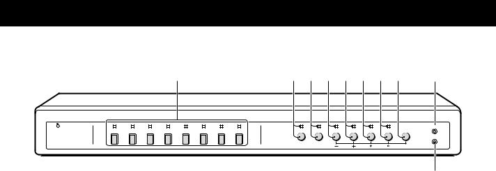
FRONT PANEL
1 |
2 |
3 4 5 6 7 8 9 |
F |
||
|
1 2 3 4 5 6 7 8 |
|
|
|
ALL RESET |
POWER |
STILL |
ZOOM |
SEQUENCE QUAD LIVE VCR MENU |
|
|
|
|
|
|
|
MENU RESET |
|
|
EXIT |
NEXT |
|
|
G
This unit is not equipped with a power switch. The power is turned on/off when the supplied power cord is connected/disconnected at the power source.
1 POWER indicator
2Camera select buttons and camera indicators
Use these buttons to select the picture from the corresponding camera. When a camera is selected, the corresponding indicator will light.
3STILL button and indicator
In live picture quad screen display mode, press this button to set the freeze mode.
4ZOOM button and indicator
In live picture quad screen display mode, press this button to set the 2x zoom in mode.
5 SEQUENCE button and indicator
7LIVE button and indicator
Press this button to select the live input mode.
8VCR button and indicator
Press this button to select the VCR playback input mode.
9MENU button (see page 7)
Press this button to display the menus. Press repeatedly to select the different menus in order. Buttons 3 to 8 are used for menu control.
F ALL RESET button (see page 8)
G MENU RESET button (see page 8)
Press this button for an automatic sequential quad screen or full screen display of the pictures.
6QUAD button and indicator
In live picture mode, press this button repeatedly to switch between quad screens A and B.
English |
3 |
PARTS NAMES
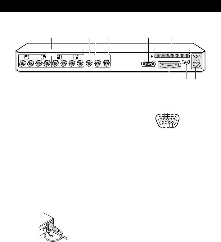
REAR PANEL
|
|
|
|
1 |
|
|
|
2 3 |
4 |
5 |
6 |
|
1 |
5 |
2 |
CAMERA |
7 |
4 |
8 |
VCR |
VIDEO OUT |
CONTROL |
|
||
6 |
3 |
IN |
QUAD |
QUAD |
|
|||||||
|
|
|
|
|
|
|
|
|
FULL |
ONLY |
|
RC C SW C AL C 1 2 3 4 5 6 7 8 |
|
|
|
|
|
|
|
|
|
|
|
RS232C |
|
7 8 9
1 CAMERA input terminals (1 – 8)
2 VCR IN (Video cassette recorder input) terminal
3VCR OUT QUAD FULL (Video signal output) terminal
Output in quad screen and full screen display modes.
4VCR OUT QUAD ONLY (Video signal output) terminal
Output only in quad screen display mode.
However, the output display mode at this terminal can be switched from quad screen mode only to quad screen and full screen display modes (see (MONITOR SET) on page 22, and Tables 1 and 2 on pages 23 and 24).
5RS232C (RS-232C) terminal
To control this unit using a personal computer, connect the computer serial terminal to this terminal using a 9-pin D-SUB cable (sold separately).
6 CONTROL terminal
7 Battery compartment
8Power cord holder
Using the supplied tie, attach the power cord to the holder as illustrated.
9AC Power socket
Insert the power cord female plug firmly into this socket. When the other plug of the power cord is connect to a live power source, the POWER indicator on the front panel will light.
(RS232C terminal)
1 2 3 4 5
6 7 8 9
Pin No. |
Signal |
Function |
Signal direction |
1 |
– |
– |
– |
|
|
|
|
2 |
RXD |
Data reception |
Computer →This unit |
3 |
TXD |
Data transmission |
This unit → Computer |
4 |
DTR |
Normally “H” |
|
|
|
|
|
5 |
GND |
Common |
– |
|
|
|
|
6 |
– |
– |
– |
|
|
|
|
7 |
– |
– |
– |
8 |
CTS |
No reception |
This unit → Computer |
9 |
– |
– |
– |
|
|
|
|
(CONTROL terminal)
Pin |
Signal |
RC |
Remote input |
|
|
C |
Common |
|
|
SW |
Switching input (DC 5V) |
|
|
C |
Common |
AL |
Alarm input (DC 5V) |
|
|
C |
Common |
1 |
Alarm input 1 |
|
|
2 |
Alarm input 2 |
|
|
3 |
Alarm input 3 |
4 |
Alarm input 4 |
|
|
5 |
Alarm input 5 |
|
|
5 |
Alarm input 6 |
|
|
7 |
Alarm input 7 |
|
|
8 |
Alarm input 8 |
4 |
English |

CONNECTION
Before making any connection, make sure all the devices are turned off.
Before making the connections, please refer to the instruction manual accompanying each device. If the devices are not connected properly, that may cause a fire and/or damages.
RECORDING LIVE PICTURES IN QUAD SCREEN DISPLAY MODE ONLY CONNECTIONS
01 |
05 |
02 |
06 |
01 |
05 |
02 |
06 |
|
01 |
|
05 |
01 |
02 |
05 |
06 |
03 |
04 |
07 |
08 |
Monitor (sold separately)
|
|
|
|
|
|
|
|
|
|
|
|
1 |
2 |
Live pictures in |
|
|
|
|
|
|
|
|
|
|
|
|
|
|
|
|
|
|
|
|
|
|
|
|
|
|
|
3 |
4 |
quad screen/full |
|
|
|
|
|
|
|
|
|
|
|
|
|
|
screen display |
|
|
|
|
|
|
|
|
|
|
|
|
|
External alarm sensors |
|
|
|
|
|
|
|
|
|
|
|
|
|
(door bell, interphone, etc.) |
||
1 |
5 |
2 |
CAMERA |
7 |
4 |
8 |
VCR |
VIDEO OUT |
CONTROL |
|
|
|
||
6 |
3 |
IN |
QUAD |
QUAD |
|
|
|
|||||||
|
|
|
|
|
|
|
|
|
FULL |
ONLY |
|
RC C SW C AL C 1 2 3 |
4 5 6 7 8 |
|
|
|
|
|
|
|
|
|
|
|
|
RS232C |
|
|
|
|
|
|
|
|
|
|
|
|
|
|
Video input |
|
|
|
|
|
|
|
|
|
|
|
|
|
|
terminal |
|
|
|
Monitor (sold separately) |
|
|
|
|
|
|
Timelapse VCR (sold separately) |
Alarm input |
|
|||||
|
|
|
|
|
|
terminal |
|
|||||||
|
|
|
|
|
|
|
|
|
|
|
|
|
||
|
1 |
2 |
|
|
|
|
|
|
|
|
|
|
Common |
|
|
|
|
|
|
|
|
|
|
|
|
|
|
||
|
3 |
4 |
Video input |
|
Video output |
|
|
|
|
|
|
|||
|
|
|
terminal |
|
|
terminal |
|
|
|
|
Common |
|||
|
|
|
|
|
|
|
|
|
|
|
|
|
||
|
For playback in |
|
|
|
|
|
|
|
|
|
Switching output |
|||
|
quad screen only |
|
|
|
|
|
|
|
|
terminal |
|
|||
|
01 |
02 |
|
|
05 |
06 |
|
|
|
|
|
|
|
|
|
03 |
04 |
|
|
07 |
08 |
|
|
|
|
|
|
|
|
English |
|
|
|
|
|
|
|
|
|
5 |
|
|
|
|

CONNECTION
REMOTE CONTROLLER CIRCUIT CONNECTIONS
Use the layout below to make a remote controller and make the connections to the remote input pins (RC, C) of the CONTROL terminal as indicated. This will permit remote controlled operation of this unit. (make contact LOW input)
|
|
|
220Ω |
1.8kΩ |
|
|
|
|
SW 1: Camera 1 |
SW 9 |
: Still image |
|
|
|
220Ω |
2.2kΩ |
|
|
|
|
SW 2: Camera 2 |
SW 10 |
: Zoom |
|
|
|
300Ω |
3.3kΩ |
|
CONTROL |
|
|
SW 3: Camera 3 |
SW 11 |
: Camera sequential |
|
|
360Ω |
4.7kΩ |
display |
|
|
RC C SW C AL C 1 2 3 4 5 6 7 8 |
|
|||
|
|
SW 4: Camera 4 |
SW 12 |
: Quad screen |
|
|
|
|
|||
|
|
|
470Ω |
7.5kΩ |
|
RS232C |
|
|
SW 5: Camera 5 |
SW 13 |
: VCR playback |
|
|
680Ω |
13kΩ |
|
|
|
|
|
SW 6: Camera 6 |
SW 14 |
: Live picture |
|
|
|
820Ω |
27kΩ |
|
|
|
|
SW 7: Camera 7 |
SW 15 |
: Menu selection |
|
|
|
1.2kΩ |
|
|
|
|
SW: switch |
SW 8: Camera 8 |
|
|
|
|
|
|
|
INSTALLING THE RACK MOUNTING BRACKETS (SOLD SEPARATELY)
To mount this unit onto a rack, please use the rack mount hardware (model VA-RACMK 1) sold separately.
1 Insert the head of two of the supplied bolts into the |
1 |
|
keyhole opening on the side of the unit. |
||
Insert the head of the bolt in the larger side, then slide it to |
|
|
the smaller side of the opening. |
|
|
2 Align the slot on the mounting bracket with the two |
|
|
bolts. |
|
|
Make sure the bolts have not moved from their position, |
|
|
then place a flat washer, a locking washer, and fix with a |
|
|
nut. |
|
|
NOTE: |
|
|
Make sure to use the bolts provided with this unit, as the |
|
|
bolts provided with the rack mount hardware are too short. |
2 |
|
3 Install the second mounting bracket on the opposite |
||
|
||
side, then attach the unit onto the rack using the rack |
|
|
mount bolts. |
|
|
|
3 |
|
6 |
English |
BASIC OPERATIONS
MODE SWITCHING
When the unit is connected to a power source, the default display mode will be: live picture from the four cameras 1 – 4 in a quad screen. You can use the VCR, LIVE and MENU buttons to switch to the desired mode (see below for further information).
LIVE picture mode |
VCR playback mode |
LIVE picture mode |
Menu mode |
|
|
|
(LANGUAGE/LANG./IDIO.) |
|
|
|
ENGLISH |
|
|
|
FRANCAIS |
|
|
|
ESPANOL |
Power on |
VCR |
LIVE |
MENU |
|
Live Picture Mode (see page 9)
When the LIVE button is pressed, the live (direct) picture from cameras 1 – 4 connected to the camera input terminals on the unit rear panel, will be displayed. While in live picture mode you can use the still and zoom functions.
NOTE:
•The unit will automatically start in the live picture or VCR playback display mode (quad screen or full screen display) last selected. Therefore, when a mode is selected, the display mode will remain the same.
•In quad screen mode, if a camera is not connected at one of the input terminals, “NO VIDEO” will be displayed on the monitor screen.
NO |
VIDEO |
NO |
VIDEO |
NO |
VIDEO |
NO |
VIDEO |
VCR Playback Mode (see page 14)
Start playback on the VCR. If the video signal is correctly recorded, the VCR playback image will be displayed when the VCR button is pressed.
Menu Setting Mode (see page 15)
Press the MENU button to display the menu. The buttons used for menu control are indicated below.
Menu control buttons
|
|
|
|
|
|
ALL RESET |
STILL |
ZOOM |
SEQUENCE |
QUAD |
LIVE |
VCR |
MENU |
|
|
|
|
|
|
MENU RESET |
EXIT |
NEXT |
|
|
|
|
|
1 2 3 4
1 EXIT (STILL) button
To exit the menu mode.
2 NEXT (ZOOM) button
To select a sub-menu in order to set the title position, etc. Press the NEXT button to switch between the menu and the sub-menu.
3 +, – (QUAD, SEQUENCE) buttons … Press repeatedly
Use these buttons to select numbers, letters, symbols.
•+ button: for forward selection
•– button: for backward selection
4 c, l (VCR, LIVE) button … Press repeatedly
Use these buttons to move the cursor to the right or down.
•c button: will move the cursor towards the right.
•l button: will move the cursor down.
English |
7 |

BASIC OPERATIONS
SECURITY LOCK FUNCTION
This function lets you lock the camera live picture mode or VCR playback mode, so that it cannot be switched to another mode.
Security lock
Press the LIVE or the VCR button for about 3 seconds.
The buzzer will be heard and all the buttons will be locked. If a button is pressed by mistake, the buzzer is heard and the corresponding function will not operate.
LIVE VCR
or
Canceling the Security Lock
To cancel the security lock, press the same (LIVE or VCR) button again for about 3 seconds. A buzzer will be heard and the mode will be unlocked.
SETTINGS BACKUP FUNCTION
This unit is equipped with a backup battery (lithium battery) to maintain the clock settings. When the unit is used under normal conditions, the backup battery is recharged. The battery is fully recharged after a minimum of about 30 hours, and will maintain the clock settings for up to 30 days.
NOTE: The settings may not be maintained properly if the backup battery has been recharged for less than 30 hours when the power goes off.
Battery Life
If the power is turned off for about one hour or more, when the power is restored, the (CLOCK SET) menu is displayed so the clock settings can be checked.
If the clock settings are reset to: 01-01-2000 SAT 00:00:00, that may indicate that the battery is dead and must be replaced.
Replacing the Battery
To replace the battery, please consult your dealer. After the battery has been replaced, press the ALL RESET button, then in the (CLOCK SET) menu set the date and time (see page 17). Depending on the battery usage it may become necessary to change it. For replacement and disposal of the old battery, please contact your dealer.
RESET FUNCTION
The menus can be reset or cleared.
ALL RESET
LIVE |
VCR |
MENU |
MENU RESET
Using the MENU RESET Button
A:While a menu is displayed, press the MENU RESET button to reset all the values of the displayed menu to the default values.
B:If no menu is displayed, press the MENU RESET button to reset the time to the nearest hour.
NOTE: For example, between 10:30:00 and 11:29:59 the clock will be reset to 11:00:00.
Using the ALL RESET button
Press this button to reset the following:
•Reset the time and date in the (CLOCK SET) menu to the default setting.
•The display will return to the default quad screen display mode.
NOTE: If the unit does not function properly, press the
ALL RESET button.
Please note that all the settings mentioned above will be reset.
8 |
English |

LIVE PICTURE MODE
(VIDEO OUT QUADFULL) Operations with the monitor connected to the VIDEO OUT QUADFULL terminal.
LIVE |
|
VIDEO OUT |
||
1 |
2 |
QUAD |
QUAD |
|
FULL |
ONLY |
|||
|
|
|||
3 |
4 |
|
|
|
Press the LIVE button.
The live pictures from the cameras connected to the CAMERA terminals (1 – 4) on the unit back panel will be displayed.
Refer to the diagrams below for the buttons to press in order to select the desired operation mode.
LIVE PICTURE MODE OPERATIONS STEPS
b Automatic switching between quad screen A and B
|
SEQUENCE |
01 |
02 |
|
|
|
|
|
|
||
|
|
|
05 |
|
06 |
|
|
03 |
04 |
|
|
|
|
|
07 |
|
08 |
(Quad screen A) |
|
|
|
|
|
LIVE |
STILL |
4 |
01 |
02 |
|
01 |
02 |
|
|
||
03 |
04 |
|
03 |
04 |
S4 |
QUAD |
|
|
|
|
|
|
ZOOM |
4 |
01 |
02 |
|
|
|
(Quad screen B) |
|
|
|
|
|||
|
|
|
|
|
|
||
05 |
06 |
|
03 |
04 |
Z4 |
|
|
|
|
|
|
|
|
||
07 |
08 |
|
|
|
|
|
|
|
ZOOM |
4 |
01 |
STILL |
4 |
01 |
02 |
|
|
|
02 |
|
|||
|
|
|
03 |
Z4 |
|
03 |
SZ4 |
4 |
SEQUENCE |
04 01
bSelecting the quad screens A and B displayed cameras ( 21)
Settings entered in the (TIMER SET) menu.
bAutomatic sequential switching speed (delay) set for each camera ( 21, 22)
Settings entered in the (TIMER SET) and the (MONITOR SET) menus.
English |
9 |
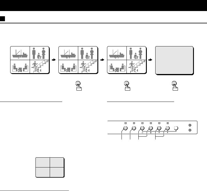
|
QUAD SCREEN OPERATIONS |
(Live picture) |
|||||||||||||||||
|
|
|
|
|
|
|
|
|
|
|
|
|
|
|
|
|
|
Press the QUAD button once. |
|
|
|
|
|
|
|
|
|
|
|
|
|
|
|
|
|
|
|
|
|
01 |
|
02 |
|
|
|
|
05 |
|
|
06 |
The camera select indicators (1 – 4) light and quad screen A is displayed. |
||||||||
|
|
|
|
|
|
|
Press the QUAD button one more time to switch to quad screen B. |
||||||||||||
|
|
|
|
|
|
|
|
|
|
|
|
|
|
|
|
|
|
||
|
|
|
|
|
|
|
|
|
|
|
|
|
|
|
|
|
NOTE: The quad screen (A or B) last selected is memorised and will be selected first |
||
03 |
|
|
|
|
04 |
|
|
|
|
07 |
|
|
08 |
||||||
|
|
|
|
|
|
|
|
|
|
||||||||||
|
|
QUAD |
|
|
QUAD |
|
when switching to quad screen mode again. |
|
|||||||||||
01 |
02 |
03 |
04 |
07 |
08 |
03 |
04 |
07 |
08 |
|
SEQUENCE |
Sequential display of quad screen A and quad screen B at 1 second interval
Press the SEQUENCE button.
Quad screen A and quad screen B are displayed sequentially at 1 second interval. The camera select indicators (1 – 4, 5 – 8) light sequentially according to the displayed quad screen.
NOTE:
The sequential display speed (screen interval) is set to 1 second in the (MONITOR SET) menu. The sequence speed setting can be set as desired, refer to “QUAD SEQ. TIMER” on page 22.
(TIMER SET)
TIME 00:00 |
00:00 |
|
||
SEQ. QUAD SEQ. QUAD |
||||
CAM1 T1 |
OFF |
T1 |
ON |
|
CAM2 T1 |
OFF |
T1 |
ON |
|
CAM3 T1 |
OFF |
T1 |
ON |
|
CAM4 T1 |
OFF |
T1 |
ON |
|
CAM5 T1 |
ON |
T1 |
OFF |
|
CAM6 T1 |
ON |
T1 |
OFF |
|
CAM7 T1 |
ON |
T1 |
OFF |
|
CAM8 T1 |
ON |
T1 |
OFF |
|
Camera number
Example 2:
Set the cameras to be ON/OFF during the day.
Selecting the quad screens A and B displayed cameras
TIMER SETTING: see page 21
Example 1: |
|
(Quad screen A) |
|
|
|
(Quad screen B) |
|||||||||||
CAMERA 1: ON |
CAMERA 5: ON |
|
|
|
|
|
|
|
|
|
|
|
|
|
|
|
|
CAMERA 2: ON |
CAMERA 6: ON |
01 |
|
|
|
02 |
|
05 |
06 |
||||||||
CAMERA 3: ON |
CAMERA 7: ON |
|
|
|
|
|
|
|
|
|
|
|
|
|
|
|
|
CAMERA 4: ON |
CAMERA 8: ON |
03 |
|
|
|
|
04 |
|
07 |
|
|
08 |
|||||
|
|
|
|
|
|
||||||||||||
Example 2: |
|
|
|
|
|
|
|
|
|
|
|
|
|
|
|
|
|
CAMERA 1: OFF |
CAMERA 5: ON |
|
|
|
|
|
|
|
|
|
|
|
|
|
|
|
|
CAMERA 2: OFF |
CAMERA 6: ON |
05 |
|
|
|
06 |
|
|
|
|
05 |
06 |
|||||
CAMERA 3: OFF |
CAMERA 7: ON |
|
|
|
|
|
|
|
|
|
|
|
|
|
|
|
|
CAMERA 4: OFF |
CAMERA 8: ON |
07 |
|
|
|
08 |
|
|
07 |
|
|
08 |
|||||
|
|
|
|
|
|||||||||||||
Example 3:
CAMERA 1: ON CAMERA 2: ON CAMERA 3: ON CAMERA 4: ON
Example 4:
CAMERA 1: OFF CAMERA 2: OFF CAMERA 3: OFF CAMERA 4: OFF
NOTE:
CAMERA 5: OFF CAMERA 6: OFF CAMERA 7: OFF CAMERA 8: OFF
CAMERA 5: OFF CAMERA 6: OFF CAMERA 7: OFF CAMERA 8: OFF
01 02
 03
03
 04
04
01 02
 03
03
 04
04
01 02
 03
03
 04
04
01 02
 03
03
 04
04
•When the timer is set, the quad screen will be selected according to the day/night settings.
•When the timer is not set, the day setting quad screen will be selected.
10 |
English |
 Loading...