


Multimedia Projector
MODEL PLC-XF60
PLC-EF60
Projection lens is optional.
Owner's Manual

Features and Design
This Multimedia Projector is designed with most advanced technology for portability, durability, and ease of use. This projector utilizes built-in multimedia features, a palette of 16.77 million colors, and matrix liquid crystal display (LCD) technology.
Compatibility |
My Logo |
||
|
|
|
|
The projector widely accepts various video and computer input signals including; Analog and Digital Computer sources, 6 TV color systems, Component video, S-video, Digital video sources compatible with HDCP and RGB scart. ( p37 and 38)
Simple Computer System Setting
The projector has the Multi-scan system to conform to almost all computer output signals quickly. The projector accepts signals up to UXGA resolution. ( p39 and 72)
Convenient Fingertip Control Pad
The fingertip Control Pad on the projector's top controls and the remote control provides you a remarkable flexibility and simplicity through the On-Screen Menu navigation. ( p11, 14, 34, and 35)
Easy Menu Operation with USB Mouse
Your USB Mouse Controller can be used for the projector's menu operation. ( p26, 34, and 35)
The projector enables you to customize the starting or interval display for your presentation with its image capturing function. ( p52)
My Menu Selection
My Menu function allows you to select menu items to be displayed on screen. You can hide menus not in frequent use and make your own menu display. ( p51)
Customized Screen Setting
Fine aspect setting menu is prepared in the projector. You can adjust screen scale and position exactly what you want. ( p48)
Shutter Function
The projector is equipped with the shutter that provides complete blackness for a while the projected image is not needed with keeping the projector on. The Shutter management function allows you to set the timer. It prevents leaving the projector on with the shutter released for a long time. ( p30, 55 and 56)
Vertical and Horizontal Lens Shift and Memory
The projector is equipped with vertical and horizontal Lens |
Film Function |
|
|
The Film function reproduces pictures faithful to the original |
|
Shift and Lens Memory function, which enables you to |
|
|
obtain optimum image easily under various setup |
|
film quality from 2:3 and 2:2 pull-down video sources. |
environments. ( p30 and 55) |
|
( p47) |
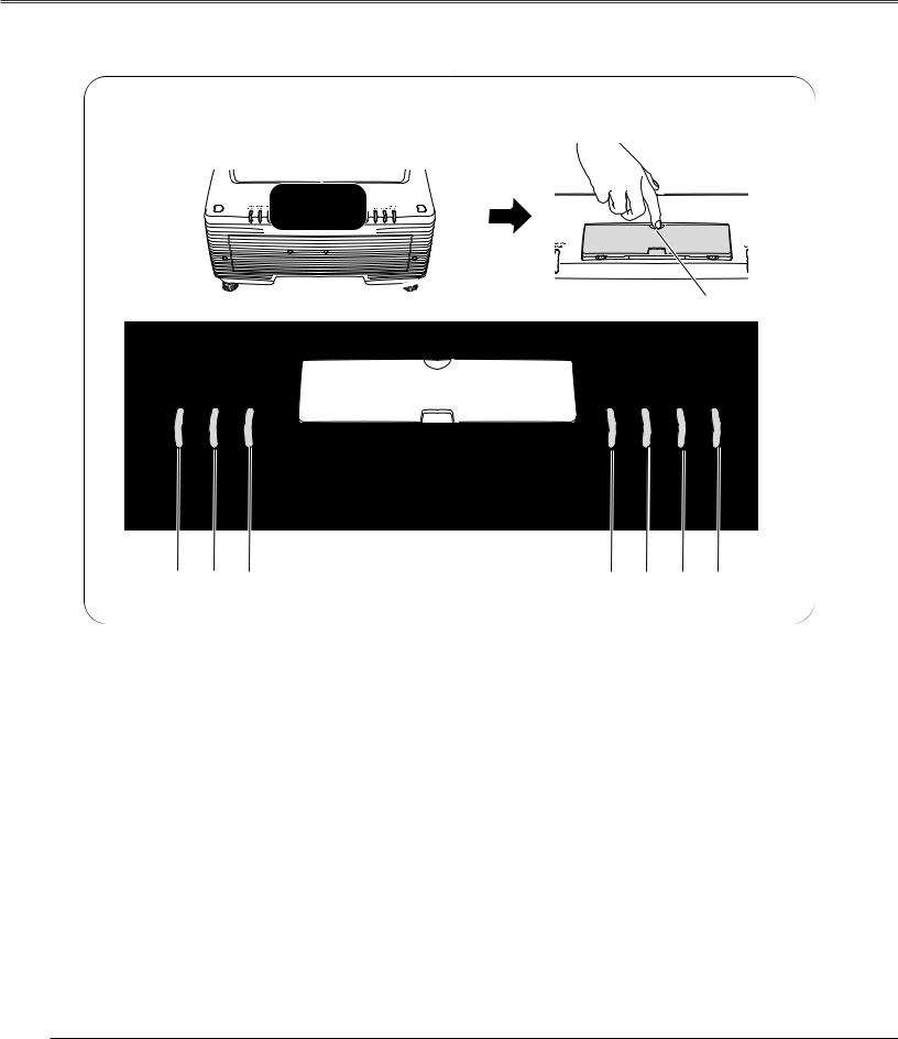
One-Touch Removable Filter and Filter LED
One-touch removable filter allows you an easy maintenance and the orange lighting filter LED tells you the best filter exchange timing. ( p63)
Various Security Functions
The following security or anti-theft functions prevent others except users from using the projector: Key Lock, PJ Lock and USB Lock. ( p28, 56, and 57)
Advanced Warp & Blending Feature
This feature responds to commercial needs by allowing edge warp and blending correction for projecting image to the spherical and cylindrical screens. With the enclosed Advanced Screen Manager application, you can make correction to the projection image from the computer connected to the projector. ( p23)
Advanced Network Feature
Advanced Network feature available by installation of the optional interface board enables various networking operations including Network Capture, Network Viewer, Network Communication, and Advanced Card Imager. Contact the sales dealer where you purchase the projector for the Advanced Network board. ( p75)
2

Table of Contents
Features and Design . . . . . . . . . . . . . . . . . . .2
Table of Contents . . . . . . . . . . . . . . . . . . . . . .3
To The Owner . . . . . . . . . . . . . . . . . . . . . . . . .4
Safety Instructions . . . . . . . . . . . . . . . . . . . .5
Air Circulation . . . . . . . . . . . . . . . . . . . . . . . . . . . . . . .6
Setup In Proper Directions . . . . . . . . . . . . . . . . . . . . .6
Moving the Projector . . . . . . . . . . . . . . . . . . . . . . . . .7
Caution in Handling the Projector . . . . . . . . . . . . . . . .7
Compliance . . . . . . . . . . . . . . . . . . . . . . . . . .8
Preparation . . . . . . . . . . . . . . . . . . . . . . . . . . .9
Parts Name . . . . . . . . . . . . . . . . . . . . . . . . . . . . . . . .9
Indicators . . . . . . . . . . . . . . . . . . . . . . . . . . . . . . . . .10
Top Control . . . . . . . . . . . . . . . . . . . . . . . . . . . . . . . .11
Terminals . . . . . . . . . . . . . . . . . . . . . . . . . . . . . . . . .12
Remote Control . . . . . . . . . . . . . . . . . . . . . . . . . . . .14
Remote Control Transmitter . . . . . . . . . . . . . . . . . . .16
Remote Control Channel and ID Setup . . . . . . . . . . .16
Remote Control Battery Installation . . . . . . . . . . . . .17
Installation . . . . . . . . . . . . . . . . . . . . . . . . . .18
Installation . . . . . . . . . . . . . . . . . . . . . . . . . . . . . . . . .18 Lens Installation . . . . . . . . . . . . . . . . . . . . . . . . . . . .18 Positioning the Projector . . . . . . . . . . . . . . . . . . . . . .18 Lens Shift Adjustment . . . . . . . . . . . . . . . . . . . . . . .19 Level Adjustable Feet . . . . . . . . . . . . . . . . . . . . . . . .19 Connecting AC Power Cord . . . . . . . . . . . . . . . . . . .20 Connection Terminals . . . . . . . . . . . . . . . . . . . . . . .21 Interface Board Slots . . . . . . . . . . . . . . . . . . . . . . . .21 Connecting to Computer
(Digital and Analog RGB) . . . . . . . . . . . . . . . . . . . . . .22 Connecting to Digital PC/AV Equipment
(Warp & Blending) . . . . . . . . . . . . . . . . . . . . . . . . . . .23 Connecting to Video Equipment
(Digital and Video) . . . . . . . . . . . . . . . . . . . . . . . . . . .24 Connecting to Video Equipment
(Component and RGB Scart) . . . . . . . . . . . . . . . . . . .25
Basic Operation . . . . . . . . . . . . . . . . . . . . . .26
Operating the Projector . . . . . . . . . . . . . . . . . . . . . .26 Basic Operation and Reference Buttons . . . . . . . . .27 Turning On the Projector . . . . . . . . . . . . . . . . . . . . .28 Turning Off the Projector . . . . . . . . . . . . . . . . . . . . .29 Lens Shift Adjustment . . . . . . . . . . . . . . . . . . . . . . .30 Zoom and Focus Adjustment . . . . . . . . . . . . . . . . . .30 Shutter Function . . . . . . . . . . . . . . . . . . . . . . . . . . . .30 Input Selection . . . . . . . . . . . . . . . . . . . . . . . . . . . . .31 Auto PC Adjustment . . . . . . . . . . . . . . . . . . . . . . . . .31 Information . . . . . . . . . . . . . . . . . . . . . . . . . . . . . . . .31 Keystone Adjustment . . . . . . . . . . . . . . . . . . . . . . . .32 Screen Selection . . . . . . . . . . . . . . . . . . . . . . . . . . . .32 Picture Freeze Function . . . . . . . . . . . . . . . . . . . . . .32 P-Timer Function . . . . . . . . . . . . . . . . . . . . . . . . . . . .32 D. Zoom +/– Function . . . . . . . . . . . . . . . . . . . . . . . .33
Volume Control . . . . . . . . . . . . . . . . . . . . . . . . . . . . .33 How to Operate On-Screen Menu . . . . . . . . . . . . . .34 Menu Icons and Their Features . . . . . . . . . . . . . . . .36
Input . . . . . . . . . . . . . . . . . . . . . . . . . . . . . . .37
Input . . . . . . . . . . . . . . . . . . . . . . . . . . . . . . . . . . . . .37
System . . . . . . . . . . . . . . . . . . . . . . . . . . . . |
. 39 |
System . . . . . . . . . . . . . . . . . . . . . . . . . . . . . . . . . . |
.39 |
PC System Selection |
39 |
Video or S-Video Signal Selection |
40 |
Component Signal Selection |
40 |
Computer Adjustment . . . . . . . . . . . . . . . . |
41 |
PC Adjustment . . . . . . . . . . . . . . . . . . . . . . . . . . . . . |
41 |
Auto PC Adjust |
41 |
Manual PC Adjust |
42 |
Image Adjustment . . . . . . . . . . . . . . . . . . . .44
Image . . . . . . . . . . . . . . . . . . . . . . . . . . . . . . . . . . . .44
Image Adjust . . . . . . . . . . . . . . . . . . . . . . . . . . . . . .45
Screen Setting . . . . . . . . . . . . . . . . . . . . . . .48
Screen Setting . . . . . . . . . . . . . . . . . . . . . . . . . . . . .48
Sound . . . . . . . . . . . . . . . . . . . . . . . . . . . . . .50
Sound . . . . . . . . . . . . . . . . . . . . . . . . . . . . . . . . . . . .50
Setting . . . . . . . . . . . . . . . . . . . . . . . . . . . . .51
Setting . . . . . . . . . . . . . . . . . . . . . . . . . . . . . . . . . . .51
Special . . . . . . . . . . . . . . . . . . . . . . . . . . . . .59
Special . . . . . . . . . . . . . . . . . . . . . . . . . . . . . . . . . . .59
Information . . . . . . . . . . . . . . . . . . . . . . . . . . . . . . . .61
Maintenance and Cleaning . . . . . . . . . . . . .62
Warning Temp Indicator . . . . . . . . . . . . . . . . . . . . . . |
62 |
Air Filter Replacement . . . . . . . . . . . . . . . . . . . . . . . |
63 |
Lamp Replacement . . . . . . . . . . . . . . . . . . . . . . . . . . |
64 |
Cleaning the Projection Lens . . . . . . . . . . . . . . . . . . |
66 |
Cleaning the Projector Cabinet . . . . . . . . . . . . . . . . . |
66 |
Attaching the Cord Cover Strap . . . . . . . . . . . . . . . . |
66 |
Indicators and Projector Condition . . . . . . . . . . . . . . |
67 |
Main Indicators |
67 |
Shutter Indicator |
68 |
Warning Filter Indicator |
68 |
Lamp Replace Indicators |
69 |
Appendix . . . . . . . . . . . . . . . . . . . . . . . . . . .70
Troubleshooting . . . . . . . . . . . . . . . . . . . . . . . . . . . .70
Compatible Computer Specifications . . . . . . . . . . . .72
Technical Specifications . . . . . . . . . . . . . . . . . . . . . .74
Optional Parts . . . . . . . . . . . . . . . . . . . . . . . . . . . . . .75
Menu Tree . . . . . . . . . . . . . . . . . . . . . . . . . . . . . . . .76
Dimensions . . . . . . . . . . . . . . . . . . . . . . . . . . . . . . . .79
Terminal Configurations . . . . . . . . . . . . . . . . . . . . . .80
PIN Code Number Memo . . . . . . . . . . . . . . . . . . . . .81
Index . . . . . . . . . . . . . . . . . . . . . . . . . . . . . . . . . . . . .82
3
To The Owner
Before operating this projector, read this manual thoroughly and operate the projector properly.
This projector provides many convenient features and functions. Operating the projector properly enables you to manage those features and maintains it in better condition for a considerable time.
Improper operation may result in not only shortening the product-life, but also malfunctions, fire hazard, or other accidents.
If your projector seems to operate improperly, read this manual again, check operations and cable connections and try the solutions in the “Troubleshooting” section in the end of this booklet. If the problem still persists, contact the dealer where you purchased the projector or the service center.
CAUTION
RISK OF ELECTRIC SHOCK
DO NOT OPEN
CAUTION : TO REDUCE THE RISK OF ELECTRIC SHOCK, DO NOT REMOVE COVER (OR BACK). NO USER-SERVICEABLE PARTS INSIDE EXCEPT LAMP REPLACEMENT. REFER SERVICING TO QUALIFIED SERVICE PERSONNEL.
THIS SYMBOL INDICATES THAT DANGEROUS VOLTAGE CONSTITUTING A RISK OF ELECTRIC SHOCK IS PRESENT WITHIN THIS UNIT.
THIS SYMBOL INDICATES THAT THERE ARE IMPORTANT OPERATING AND MAINTENANCE INSTRUCTIONS IN THE OWNER'S MANUAL WITH THIS UNIT.
Safety Precaution
WARNING : TO REDUCE THE RISK OF FIRE OR ELECTRIC SHOCK, DO NOT EXPOSE THIS APPLIANCE TO RAIN OR MOISTURE.
–This projector produces intense light from the projection lens. Do not stare directly into the lens as possible. Eye damage could result. Be especially careful that children do not stare directly into the beam.
–Install the projector in a proper position. If not, it may result in a fire hazard.
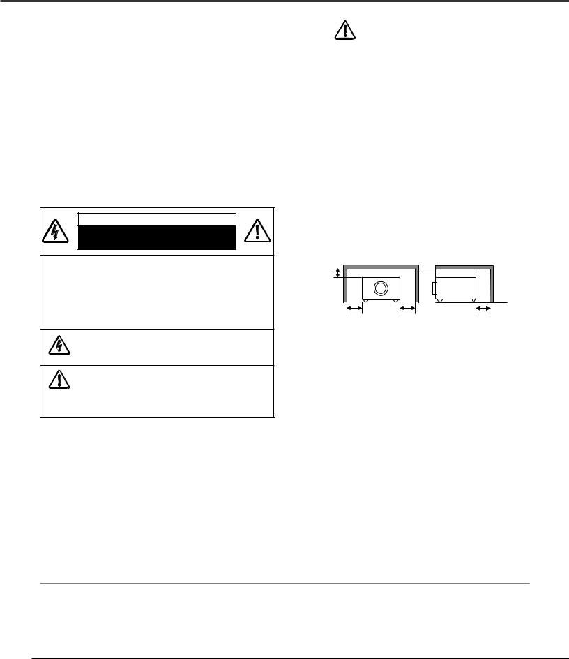
–Provide appropriate space on the top, sides and rear of the projector cabinet for allowing air circulation and cooling the projector. Minimum clearance must be maintained. If the projector is to be built into a compartment or similarly enclosed, the minimum distances must be maintained. Do not cover the ventilation slot on the projector. Heat buildup can reduce the service life of your projector, and can
also be dangerous.
SIDE and TOP REAR
3.3'(1m)
3.3'(1m) |
3.3'(1m) |
3.3'(1m) |
–Do not put any flammable object or spray can near the projector, hot air is exhausted from the ventilation holes.
–If the projector is not to be used for an extended time, unplug the projector from the power outlet.
READ AND KEEP THIS OWNER'S MANUAL FOR LATER USE.
CAUTION
Not for use in a computer room as defined in the Standard for the Protection of Electronic Computer/Data Processing Equipment, ANSI/NFPA 75.
Ne peut être utilisé dans une salle d’ordinateurs telle que définie dans la norme ANSI/NFPA 75 Standard for Protection of Electronic Computer/Data Processing Equipment
Trademarks
Each name of corporations or products in this book is either a registered trademark or a trademark of its respective corporation.
Remark
Any graphic and figure in this manual are subject to change without notice.
4
Safety Instructions
All the safety and operating instructions should be read before the product is operated.
Read all of the instructions given here and retain them for later use. Unplug this projector from AC power supply before cleaning. Do not use liquid or aerosol cleaners. Use a damp cloth for cleaning.
Follow all warnings and instructions marked on the projector.
For added protection to the projector during a lightning storm, or when it is left unattended and unused for long periods of time, unplug it from the wall outlet. This will prevent damage due to lightning and power line surges.
Do not expose this unit to rain or use near water... for
example, in a wet basement, near a swimming pool, etc...
Do not use attachments not recommended by the manufacturer as they may cause hazards.
Do not place this projector on an unstable cart, stand, or table. The projector may fall, causing serious injury to a child or adult, and serious damage to the projector. Use only with a cart or stand recommended by the manufacturer, or sold with the projector. Wall or shelf mounting should follow the manufacturer's instructions, and should use a mounting kit approved by the manufacturers.
An appliance and cart combination should be moved with care. Quick stops, excessive force, and uneven surfaces may cause the appliance and cart combination to overturn.
Slots and openings in the back and bottom of the cabinet are provided for ventilation, to ensure reliable operation of the equipment and to protect it from overheating.
The openings should never be covered with cloth or other materials, and the bottom opening should not be blocked by placing the projector on a bed, sofa, rug, or other similar surface. This projector should never be placed near or over a radiator or heat register.
This projector should not be placed in a built-in installation such as a book case unless proper ventilation is provided.
Never push objects of any kind into this projector through cabinet slots as they may touch dangerous voltage points or short out parts that could result in a fire or electric shock. Never spill liquid of any kind on the projector.
Do not install the projector near the ventilation duct of airconditioning equipment.
This projector should be operated only from the type of power source indicated on the marking label. If you are not sure of the type of power supplied, consult your authorized dealer or local power company.
Do not overload wall outlets and extension cords as this can result in fire or electric shock. Do not allow anything to rest on the power cord. Do not locate this projector where the cord may be damaged by persons walking on it.
Do not attempt to service this projector yourself as opening or removing covers may expose you to dangerous voltage or other hazards. Refer all servicing to qualified service personnel.
Unplug this projector from wall outlet and refer servicing to qualified service personnel under the following conditions:
a.When the power cord or plug is damaged or frayed.
b.If liquid has been spilled into the projector.
c.If the projector has been exposed to rain or water.
d.If the projector does not operate normally by following the operating instructions. Adjust only those controls that are covered by the operating instructions as improper adjustment of other controls may result in damage and will often require extensive work by a qualified technician to restore the projector to normal operation.
e.If the projector has been dropped or the cabinet has been damaged.
f.When the projector exhibits a distinct change in performance-this indicates a need for service.
When replacement parts are required, be sure the service technician has used replacement parts specified by the manufacturer that have the same characteristics as the original part. Unauthorized substitutions may result in fire, electric shock, or injury to persons.
Upon completion of any service or repairs to this projector, ask the service technician to perform routine safety checks to determine that the projector is in safe operating condition.
Voor de klanten in Nederland
Bij dit produkt zijn batterijen geleverd.
Wanneer deze leeg zijn, moet u ze niet weggooien maar inleveren
NL als KCA.
5
Safety Instructions
Air Circulation
Openings in the cabinet are provided for ventilation and to ensure reliable operation of the product and to protect it from overheating, and these openings must not be blocked or covered.
 CAUTION
Hot air is exhausted from the exhaust vent. When using or installing the projector, the following precautions should be taken.
–Do not put any flammable objects near the vent.
–Keep the exhaust vent at least 3’(1m) away from any objects.
–Do not touch a peripheral part of the exhaust vent, especially screws and metallic part. This area will become hot while the projector is being used.
–Do not put anything on the cabinet. The materials put on the cabinet will not only get damaged but also cause fire hazard by heat.
Cooling fans are provided to cool down the projector. This projector monitors internal temperature and control the running speed of the cooling fans.
Exhaust Vent (Hot air exhaust)
Air Intake Vent
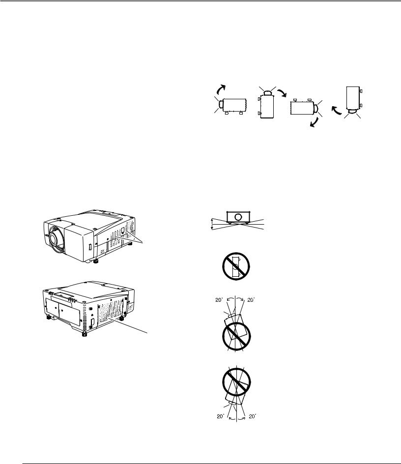
Setup In Proper Directions
Use the projector properly in specified positions. Improper positioning may reduce the lamp life and result in severe accident or fire hazard.
This projector is allowed to project the picture in any position of 360 degrees such as upward, downward, or backward as below.
Bottom |
Front |
Bottom |
Front |
Downward |
Upward |
Upward |
Downward |
(Usual) |
|
|
|
Positioning Precautions
When installing the projector, avoid positioning it as described below:
20˚
Do not tilt the projector more than 20
degrees above and below.
20˚
Do not put the projector on either side to project an image.
In upward projection, do not tilt the projector over 20 degrees right and left.
In downward projection, do not tilt the projector over 20 degrees right and left.
6
Safety Instructions
Moving the Projector
Carry the projector by two or more people holding the carrying handle.
Disconnect all the cables from the projector before moving the projector. Moving the projector with the cables connected may cause damage to the projector or result in serious injury.
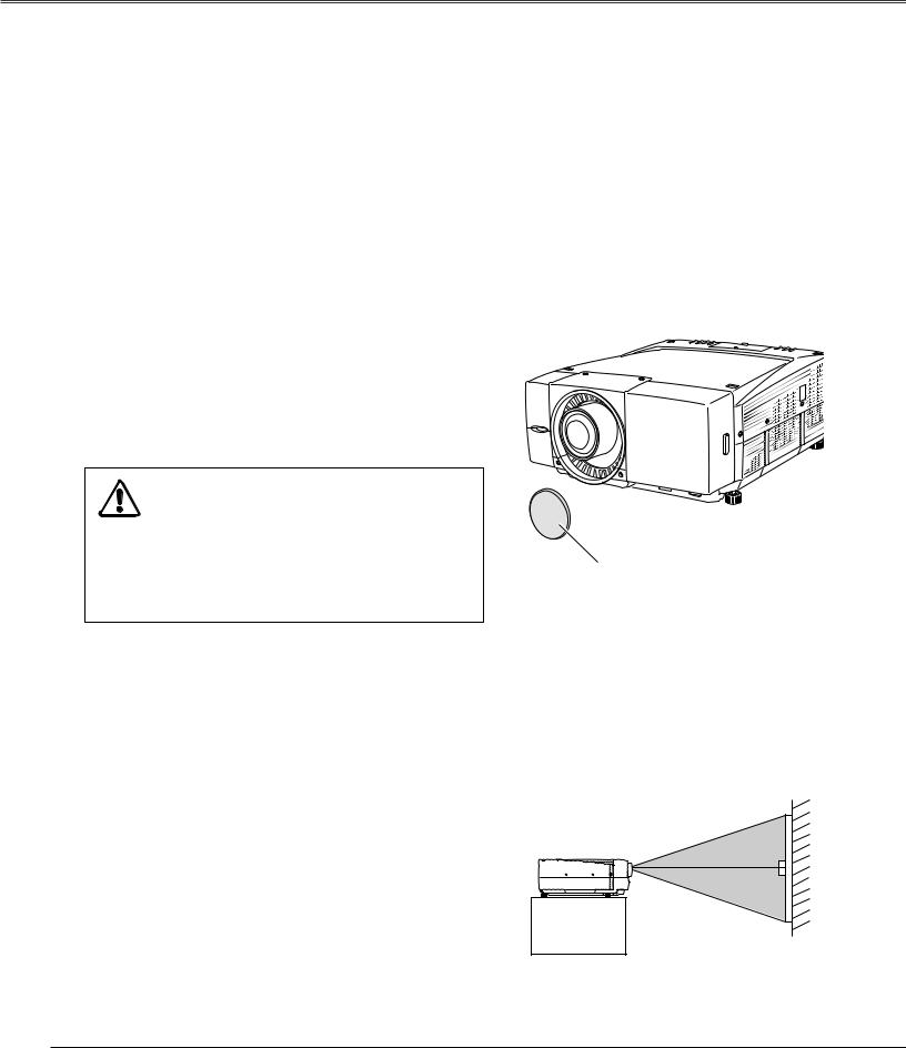
Retract the projector's adjustable feet and replace the lens cover to protect the lens surface when moving the projector.
USE CAUTION IN CARRYING OR
TRANSPORTING THE PROJECTOR
–Do not drop or bump a projector, otherwise damages or malfunctions may result.
–When carrying a projector, use a suitable carrying case.
–Do not transport a projector by using a courier or transport service in an unsuitable transport case. This may cause damage to a projector. To transport a projector through a courier or transport service, consult your dealer for their information.
REMOVE LENS FROM THE PROJECTOR WHEN CARRYING. OTHERWISE, IT MAY CAUSE SERIOUS DAMAGE TO LENS AND THE PROJECTOR.
WHEN TRANSPORT OR STORE THE PROJECTOR WITHOUT LENS, REPLACE THE LENS COVER PLATE INITIALLY ATTACHED TO THE PROJECTOR. TRANSPORTING OR STORING WITHOUT THE LENS COVER PLATE MAY CAUSE DUST TO GET INSIDE THE PROJECTOR AND RESULT IN MALFUNCTION OF THE PROJECTOR OR DAMAGE OF THE OPTICAL COMPONENTS INSIDE THE PROJECTOR.
Carrying Handle
Lens Cover
Replace the Lens cover when carrying or not using the projector.
Do not place on an unflat surface and check no object under the cabinet.
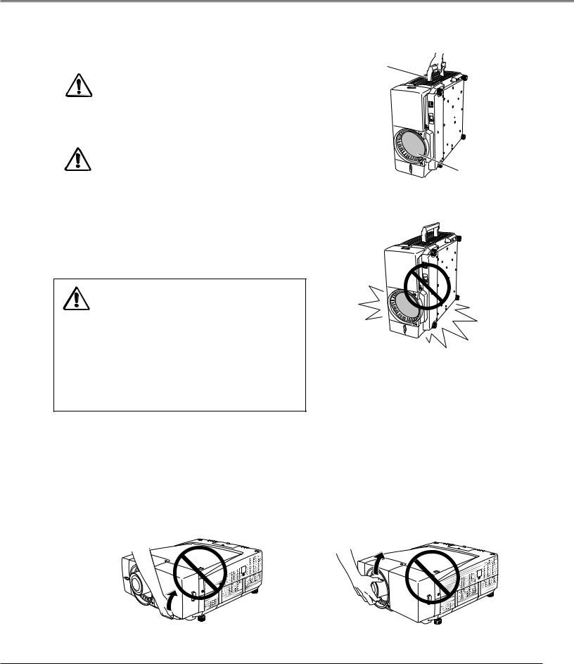
Caution in Handling the Projector
Do not hold the terminal cover when lifting or moving the projector, or may cause damage to the terminal cover or result in personal injury.
Do not hold the lens when lifting or moving the projector, or may cause damage to the lens and the projector.
Be sure the surface is flat and no object is under the projector when placing the projector either side up. Uneven surface or any object under the projector may cause damage to its cabinet. Especially be careful of the cabinet area around the exhaust vent.
Do not hold the Cover. |
Do not hold the Lens and the peripheral part. |
7
Compliance
Federal Communication Commission Notice
This equipment has been tested and found to comply with the limits for a Class A digital device, pursuant to Part 15 of FCC Rules. These limits are designed to provide reasonable protection against harmful interference when the equipment is operated in a commercial environment. This equipment generates, uses, and can radiate radio frequency energy and, if not installed and used in accordance with the instruction manual, may cause harmful interference to radio communications. Operation of this equipment in a residential area is likely to cause harmful interference in which case the user will be required to correct the interference at his own expense.
Do not make any changes or modifications to the equipment unless otherwise specified in the instructions. If such changes or modifications should be made, you could be required to stop operation of the equipment.
CAUTION
This is a Class A equipment. This equipment can cause interference in residential areas; in this case, the operator can be asked to take adequate countermeasures.
AC Power Cord Requirement
The AC Power Cord supplied with this projector meets the requirement for use in the country you purchased it.
AC Power Cord for the United States and Canada :
AC Power Cord used in the United States and Canada is listed by the Underwriters Laboratories (UL) and certified by the Canadian Standard Association (CSA).
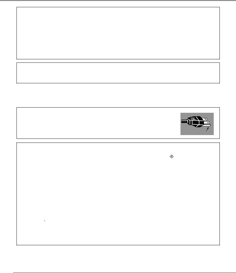
AC Power Cord has a grounding-type AC line plug. This is a safety feature to be sure that the plug will fit into the power outlet. Do not try to defeat this safety feature. Should you be unable to insert the plug into the
outlet, contact your electrician. |
GROUND |
|
AC Power Cord for the United Kingdom :
This cord is already fitted with a moulded plug incorporating a fuse, the value of which is indicated on the pin face of the plug. Should the fuse need to be replaced, an ASTA approved BS 1362 fuse must be used of the same rating, marked thus ASA . If the fuse cover is detachable, never use the plug with the cover omitted. If a replacement fuse cover is required, ensure it is of the same colour as that visible on the pin face of the plug (i.e. red or orange). Fuse covers are available from the Parts Department indicated in your User Instructions.
If the plug supplied is not suitable for your socket outlet, it should be cut off and destroyed. The end of the flexible cord should be suitably prepared and the correct plug fitted. (See Over)
WARNING : A PLUG WITH BARED FLEXIBLE CORD IS HAZARDOUS IF ENGAGED IN A LIVE SOCKET OUTLET.
The Wires in this mains lead are coloured in accordance with the following code: Green-and-yellow ············ Earth
Blue ································· Neutral Brown ······························ Live
As the colours of the wires in the mains lead of this apparatus may not correspond with the coloured markings identifying the terminals in your plug proceed as follows:
The wire which is coloured green-and-yellow must be connected to the terminal in the plug which is marked by the letter E or by the safety earth symbol  or coloured green or green-and-yellow.
The wire which is coloured blue must be connected to the terminal which is marked with the letter N or coloured black. The wire which is coloured brown must be connected to the terminal which is marked with the letter L or coloured red.
WARNING : THIS APPARATUS MUST BE EARTHED.
THE SOCKET-OUTLET SHOULD BE INSTALLED NEAR THE EQUIPMENT AND EASILY ACCESSIBLE.
8

Preparation
Parts Name
|
|
|
|
q Remote Receiver |
|
Front |
|
|
|
w Projection Lens (Option) |
|
|
|
|
|
e Front Cover (inside Terminals) |
|
|
|
|
|
r Speaker |
|
|
|
|
|
t Carrying Handle |
|
|
|
|
|
y Air Exhaust Vent |
|
|
|
|
|
CAUTION |
|
|
|
|
|
Hot air is exhausted from the exhaust vent. |
|
|
|
|
|
Do not put heat-sensitive objects near this |
|
|
|
|
|
side. |
|
q w |
e |
r |
t y |
|
|
|
|
|
|
CAUTION |
|
|
|
|
|
This projector is equipped with cooling fans |
|
Back |
|
|
|
for protection from overheating. Pay attention |
|
u |
i u |
o |
!0 |
to following to ensure proper ventilation and |
|
avoid a possible risk of fire and malfunction. |
|||||
|
|
|
|
||
|
|
|
|
● Do not cover vent slots. |
|
|
|
|
|
● Keep projector sides clear of any objects. |
|
|
|
|
|
Obstructions may block cooling air. |
|
|
|
|
|
u Indicators |
|
|
|
|
|
i Top Controls |
|
|
|
|
|
o Air Intake Vent |
|
|
|
|
|
!0Air Filter (inside) |
|
|
|
|
|
!1Speaker |
|
|
!2 |
|
!1 |
!2Lamp Cover |
|
Bottom |
!3 |
|
|
|
|
|
|
|
!3Adjustable Feet |
!3
Preparation
9
Preparation
Indicators
Press here to open the Top Lid and then top controls appear. (See next page.)
q
Turns draws
wWARNING TEMP indicator
Blinks red when the internal temperature of the projector is abnormally high. (p62,67)
eWARNING FILTER indicator
Lights orange when the projector's filter is clogged with dust. (p63, 68)
rLAMP indicator
Lights red when the projector is in the stand-by mode, and turns dim lighting when the projector is turned on. (p67)
turned on is under
Blinks green in Power Management mode or when the projector is shutdown due to power failure.
ySHUTTER indicator
Lights blue when the shutter is released. (p68)
uLAMP2 REPLACE indicator
Turns orange when the life of the projection lamp2 draws to an end. (p64, 69)
10
Preparation
Top Control
q |
w |
e |
r |
t |
y |
u |
Preparation |
LENS |
MENU |
|
|
|
AUTO |
INPUT |
|
SHIFT |
|
|
|
PC ADJ. |
|
||
ZOOM |
CANCEL |
|
|
|
INFO. |
SHUTTER |
|
FOCUS |
SELECT |
|
|
|
POWER P |
|
|
!2 !1 !0
qLENS SHIFT button
Activates Lens shift function. (p30)
wMENU button
Opens or closes the On-Screen Menu. (p34, 35 )
eCANCEL button
Cancels the selection and returns to the previous menu.
rControl pad
Navigates through the menu or adjusts value in the OnScreen Menu. These are also used to pan the image in the Digital zoom + mode. (p33, 34, 35)
About Control Pad
The built-in Control Pad is a semiconductive touchpad operational with light finger touch. Glide your finger up, down, right and left on the pad to go to the desired menu, adjust values and operate various convenient features. Refer to the following pages for respective directions.
oi
tINFO. button
Displays Information. (p31)
yAUTO PC ADJ. button
Operates the Auto PC adjustment function. (p31)
uINPUT button
Switches input sources. (p31)
iSHUTTER button
Releases and opens up the built-in shutter to block out light. (p30)
oPOWER ON-OFF button
Turns the projector on or off. (p28, 29)
!0SELECT button
Executes the item selected. It is also used to expand/ compress the image in Digital zoom +/– mode. (p33, 34, 35)
!1FOCUS button
Adjusts focus of the image. (p30)
!2ZOOM button
Adjusts zoom of the image. (p30)
11
Preparation
Terminals
w
q
r
|
INPUT 1 |
ANALOG IN |
ANALOG OUT |
INPUT 3 |
||
AUDIO 1 DIGITAL (DVI-D) |
|
R-AUDIO-L |
||||
|
|
|
|
|
||
|
|
|
|
|
|
(MONO) |
|
INPUT 2 |
|
|
|
S-VIDEO |
|
G |
B |
R |
H/V |
V |
VIDEO/Y Cb/Pb |
Cr/Pr |
AUDIO 2 |
|
|
|
|
||
|
|
|
|
|
|
|
VIDEO/Y |
Cb/Pb |
Cr/Pr |
|
|
|
|
e
|
|
|
|
|
|
|
|
|
|
|
|
|
|
|
|
|
|
|
|
|
|
|
|
q INPUT 1 terminals |
e INPUT 3 terminals |
||||||||||
AUDIO 1 |
|
|
AUDIO (R-L) |
||||||||
Connect the audio output from a computer or video |
|
|
Connect the audio output from video equipment |
||||||||
equipment connected to DIGITAL (DVI-D) or ANALOG |
|
|
connected to VIDEO/Y Cb/Pb Cr/Pr jacks or S-VIDEO |
||||||||
IN terminal to this jack. (p22, 24) |
|
|
jack to these jacks. (When the audio output is |
||||||||
DIGITAL (DVI-D) (HDCP compatible) |
|
|
monaural, connect it to L(MONO) jack. (p24, 25) |
||||||||
Connect digital output signal from a computer or |
|
|
VIDEO/Y, Cb/Pb, and Cr/Pr |
||||||||
video equipment to this terminal with a DVI-D cable. |
|
|
Connect video or component output (Y, Cb/Pb and |
||||||||
(p22, 24) |
|
|
Cr/Pr) from video equipment to these jacks with a |
||||||||
ANALOG IN |
|
|
video cable (RCA-type). (p24, 25) |
||||||||
Connect analog output signal from a computer or a |
|
|
S-VIDEO |
||||||||
video equipment (Component or RGB Scart) to this |
|
|
Connect S-Video output from video equipment to this |
||||||||
terminal with a VGA cable, a Scart-VGA or a |
|
|
jack. (p24) |
||||||||
Component-VGA cable. (p22) |
|
|
|
|
|
||||||
|
|
|
|
|
|
|
r INPUT 2 terminals |
||||
w ANALOG OUT |
|
|
|
|
|
||||||
This terminal can be used for analog signal output |
|
|
AUDIO 2 |
||||||||
incoming through the ANALOG IN terminal (INPUT 1). |
|
|
Connect the audio output from video equipment |
||||||||
Connect this terminal to the other monitor with a VGA |
|
|
connected to VIDEO/Y, Cb/Pb, and Cr/Pr jacks or G, |
||||||||
cable. (p22) |
|
|
B, R, H/V, and V jacks to this jack. (p22, 25) |
||||||||
|
|
|
|
|
|
|
|
|
VIDEO/Y, Cb/Pb, and Cr/Pr |
||
|
|
|
|
|
|
|
|
|
Connect video or component output (Y, Cb/Pb and |
||
|
|
|
|
|
|
|
|
|
Cr/Pr) from video equipment to these jacks with a |
||
|
|
|
|
|
|
|
|
|
video cable (BNC-type). (p25) |
||
|
|
|
|
|
|
|
|
|
G, B, R, H/V, and V |
||
|
|
|
|
|
|
|
|
|
Connect RGB output signal from a computer with a |
||
|
|
|
|
|
|
|
|
|
computer cable (5 BNC-type) to these jacks. (p22) |
||
12
Preparation
q
w
u |
y |
t |
r |
e |
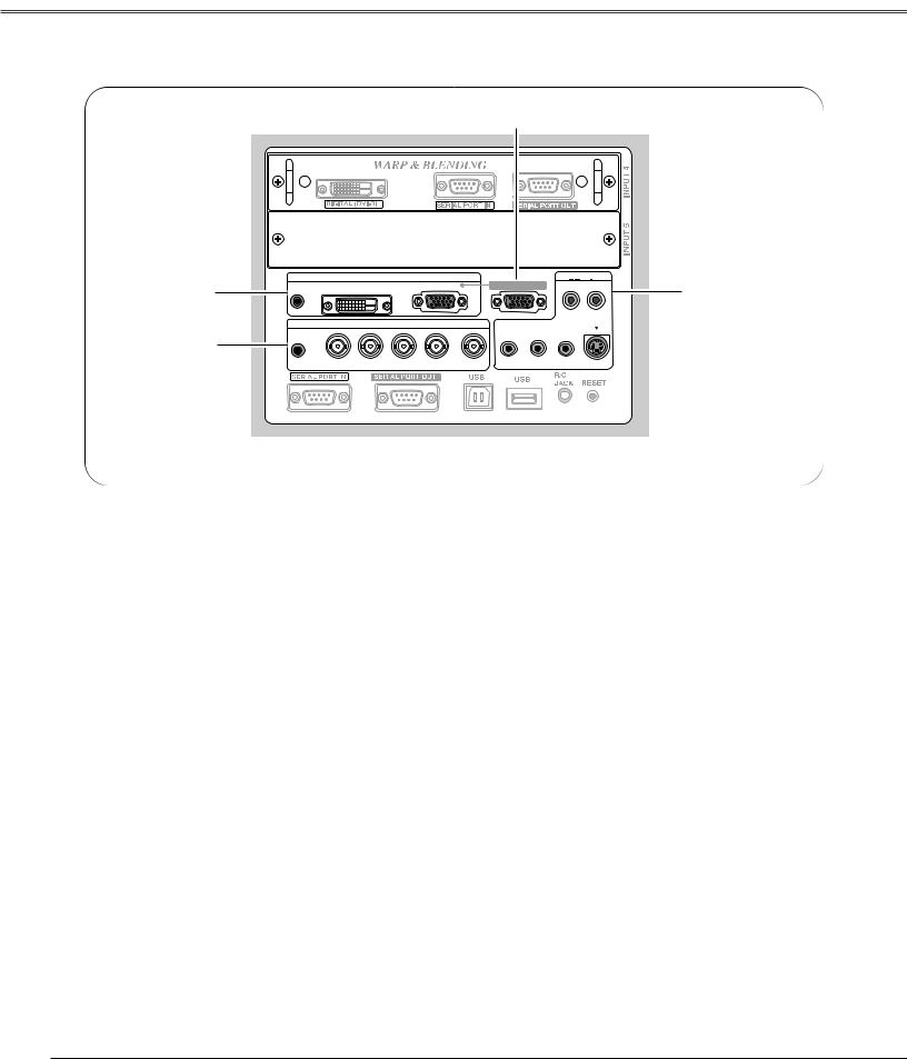
q INPUT 4 (WARP & BLENDING board)
DIGITAL (DVI-D) (HDCP compatible)
Connect digital output signal from a computer or video equipment to this terminal with a DVI-D cable. (p23)
SERIAL PORT IN
When operating Warp and Blending feature, connect serial port of the computer and this terminal with a serial cross cable (commercially supplied). (p23)
SERIAL PORT OUT
When using Warp and Blending feature for more than two projectors from a computer connected to the SERIAL PORT IN terminal above, connect SERIAL PORT IN terminal on the other projector and this terminal with a serial cross cable (commercially supplied). (p23)
Note:
Refer to the enclosed operation manual for Warp and Blending in Advanced Screen Manager.
wINPUT 5 (Vacant for Optional Interface Board)
Optional interface board can be installed into this slot. This input accepts digital signals only. (p21, 75)
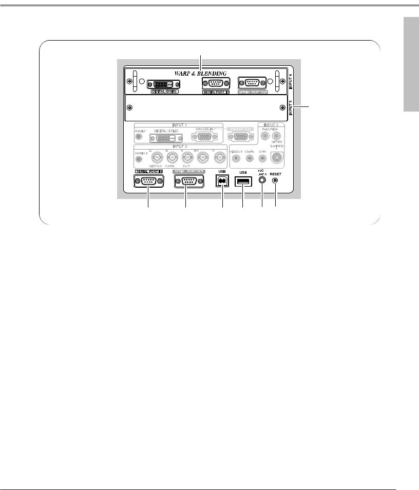
eR/C JACK
Connect the remote control to this jack with the supplied remote control cable to use the remote control as wired. (p26)
rUSB
Connect a USB mouse (commercially available) to control On-Screen Menu. (p26)
tUSB (Series B)
This port is used for the projector maintenance.
ySERIAL PORT OUT
This terminal outputs signal from SERIAL PORT IN. When controling more than two projectors from a computer, connect the other projector to this terminal with a serial cross cable (commercially supplied).
uSERIAL PORT IN
When controling the projector from a computer, connect the computer to this terminal with a serial cross cable (commercially supplied).
A built-in micro processor which controls this unit may occasionally malfunction and need to be reset. This can be done by pressing the RESET
button with a pen, which will shut down and restart the unit. Do not use the RESET function excessively.
Preparation
13
Preparation
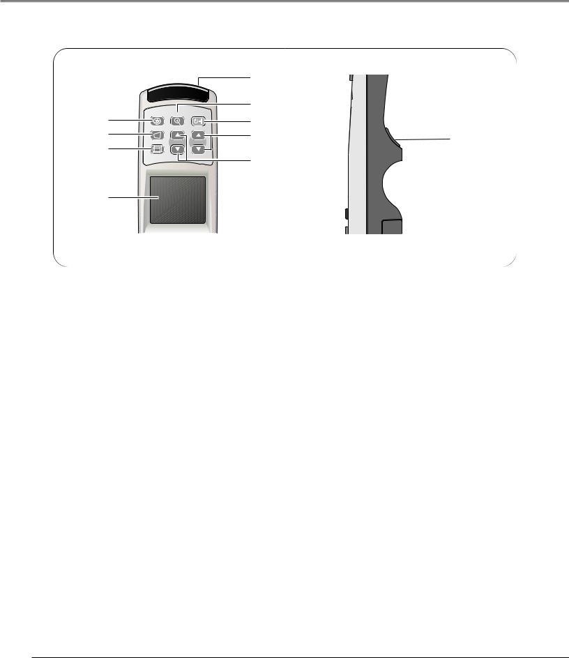
Remote Control
|
|
|
t |
|
|
|
|
y |
|
q |
SHUTTER D.ZOOM ON-OFF |
u |
|
|
|
|
|
||
w |
KEYSTONE |
|
i |
|
|
|
!0 |
||
|
LENS SHIFT ZOOM |
FOCUS |
|
|
e |
|
|
||
|
|
|
|
|
o
r
qSHUTTER button
Releases the built-in shutter for light blocking. (p30)
wKEYSTONE button
Corrects keystone distortion. (p32)
eLENS SHIFT button
Activates LENS SHIFT function. (p30)
rCONTROL PAD (semiconductive touchpad)
Selects an item or adjusts value in the On-Screen Menu. This is also used to pan the image in the Digital zoom + mode. (p33)
t WIRED REMOTE JACK
Connect the Remote Control Cable to this jack.
Battery installation is required regardless if it is used as wired or wireless. (p16, 26)
yD.ZOOM button
Activates D.Zoom +/– function. (p33)
uPOWER ON-OFF button
Turns the projector on or off. (p28, 29)
iFOCUS buttons
Adjust focus of the image. (p30)
oZOOM buttons
Adjust zoom of the image. (p30)
!0SELECT button
Executes the item selected.
14
Preparation
 i
i
CANCEL
|
MENU |
|
o |
q |
INFO |
AUTO PC |
|
|
|
!0 |
|
w |
|
|
|
|
FREEZE |
SCREEN |
|
e |
VOL. |
|
!1 |
|
SOUND |
P-TIMER |
INPUT 1 |
r |
MUTE |
|
!2 |
t |
|
INPUT 4 |
INPUT 2 |
CH |
|
|
|
y |
REMOTE |
INPUT 5 |
INPUT 3 |
ID |
|
!3 |
|
|
|
|
|
u |
|
|
!4 |
|
REMOTE |
RESET ON ALL OFF |
|
Preparation
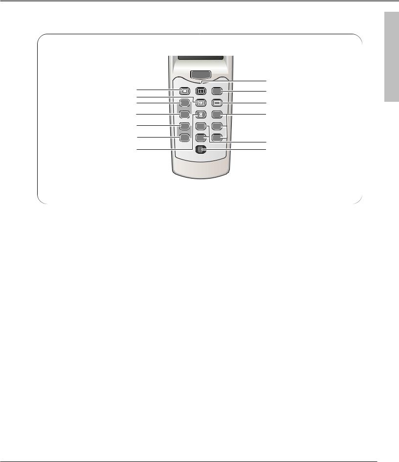
eVOL. button
Adjusts volume. (p33)
rMUTE button
Mutes sound. (p33)
tCH button
Switches Remote Control Channel (CH). (p16)
yID button
Switches Remote Control ID. (p16)
iCANCEL button
Cancels the selection and returns to the previous menu. (p34)
oINFO button
Displays the projector information. (p31)
!3INPUT 4-5 buttons
Selects input source (INPUT 4 - INPUT 5). (p31)
the CH and ID buttons at the same time to initialize the Remote Control ID and CH. (p16)
15
Preparation
Remote Control Transmitter
This wireless remote control uses radio frequency signal. You can switch four frequency channels prepared and select a remote control ID from eight IDs. The Remote Control Channel selection prevents radio frequency interference from the other equipment and the Remote Control ID selection allows you to operate several projectors with their respective remote controls without mutual interference among those projectors.
Wired Remote Control Transmitter
The remote control can be used as a wired remote control. When interference between the projector and other equipment occurs or the projector is used in a place where the operation of radio equipment is restricted, connect the remote control and the projector with the remote control cable provided. Connected with the remote control cable, the remote control does not emit radio signal.
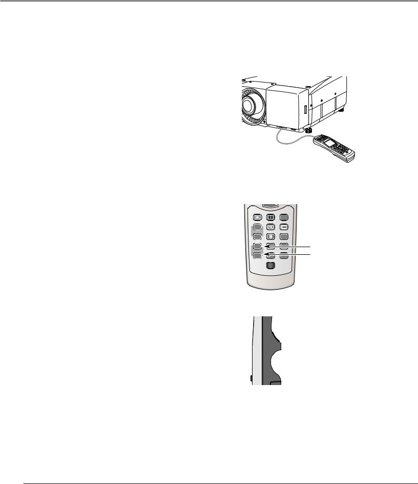
Remote Control Channel and ID Setup
Initial Remote Control Channel and ID are CH1 and ID1. When you change the setting, set a Channel first, and then an ID.
Channel and ID settings for the remote control should be the same as those for the projector. When changing the CH and ID settings to the remote control, do it to the projector as well. Refer to "Remote Control " in Setting menu on page 53.
Should you be lost at which CH and ID are currently set, initialize the Channel and ID once, and set them again.
MENU |
INFO |
AUTO PC |
|
FREEZE |
SCREEN |
VOL. |
|
|
SOUND |
P-TIMER |
INPUT 1 |
MUTE |
|
|
|
4 |
INPUT 2 |
|
|
CH button |
|
|
INPUT 3 |
ID button
REMOTE RESET ON ALL OFF
1 Set the Remote Control Channel
With holding down the CH button, press the SELECT button. The Remote Control Channel switches sequentially for one pressing the SELECT button. (See Table1 on next page.)
2 Set the Remote Control ID
With holding down the ID button, press the SELECT button. The Remote Control ID switches sequentially for one pressing the SELECT button. (See Table2 on next page.)
Initialize the Remote Control Channel and ID
With holding down the CH and ID buttons together, slide the REMOTE RESET/ON/ALL-OFF switch to REMOTE RESET, and then to ON. The initial Channel and ID are CH1 and ID1. (p15)
Note:
Remote Control Channel and ID cannot be initialized separately.

 SELECT button
While pressing the CH/ID button, press the SELECT button number of times corresponding to the remote control CH/ID.
16
Preparation
|
|
Channel switches sequentially for |
|
ID switches sequentially for one |
||
Remote Control CH |
Radio Frequency |
one pressing the SELECT button. |
Remote Control ID |
pressing the SELECT button. |
||
|
|
|
|
|
|
|
CH 1 |
2.472 GHz |
|
|
ID 1 |
|
|
|
|
|
|
|||
|
|
|
|
|
|
|
CH 2 |
2.403 GHz |
|
|
ID 2 |
|
|
|
|
|
|
|
|
|
CH 3 |
2.446 GHz |
|
|
ID 3 |
|
|
|
|
|
|
|
|
|
CH 4 |
2.421GHz |
|
|
ID 4 |
|
|
|
|
|
|
|
|
|
Table1: Remote Control Channel & Frequency |
ID 5 |
|
|
|||
|
|
|
||||
ID 6 |
|
|
||||
Default setting |
|
|
|
|
|
|
|
|
|
|
|
|
|
|
|
|
ID 7 |
|
|
|
|
|
|
|
|
|
|
|
|
|
|
|
|
|
|
|
|
|
ID 8 |
|
|
|
|
|
|
|
|
|
Table2: Remote Control ID
Caution about Radio Wave
The remote control operates in 2.4 GHz band, the same frequency band used for industrial, scientific, and medical equipment (such as pacemaker), as well as amateur radio stations.
Before operating the remote control, make sure no electromagnetic interference occurs and pay attention to the following cautions.
1.Be sure that there are no other devices in the area that may use the same frequency band as the remote control.
2.If any other devices are causing radio interferences, change the communication frequency channel or move to other location.
Caution in Wireless LAN Interference
Under wireless LAN environment based on IEEE 802.11b and IEEE802.11g, the remote control may not operate properly due to radio interferences. The remote control is initially set to use 2.472 GHz band (CH1) corresponding to several channels of wireless LAN.
Should the remote control not operate properly due to radio interference, switch the communication frequency channel to CH2. Yet the operating condition is not improved, try CH3 and CH4. In case of failure in every channel operation, relocate other radio equipment using 2.4 GHz band away from the remote control and the projector.
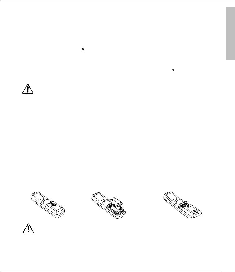
Remote Control Battery Installation
1 |
Remove the battery |
2 |
Slide the batteries into |
3 |
Replace the compartment |
compartment lid. |
the compartment. |
lid. |
Two AA size alkaline
Press the lid downward |
batteries |
|
and slide it. |
||
For correct polarity (+ and |
||
|
||
|
–), be sure battery |
|
|
terminals are in contact |
|
|
with pins in compartment. |
To insure safe operation, please observe the following precautions : ● Use (2) AA, UM3 or LR6 type alkaline batteries.
● Replace two batteries at the same time.
●Do not use a new battery with a used battery.
●Avoid contact with water or liquid.
●Do not expose the remote control to moisture, or heat.
●Do not drop the remote control.
●If a battery has leaked on remote control, carefully wipe case clean and install new batteries.
●Risk of explosion if battery is replaced by an incorrect type.
●Dispose of used batteries according to the instructions.
Preparation
17
Installation
Installation
Install the projector in a safe place. Before installation, read Safety Instructions thoroughly and check the installation place. Install the projector in a place with sufficient strength to support the projector's weight. Installation on an unstable stand, cart, or ceiling may cause serious injury or accidents.
Do not place the projector where is extremely hot and humid. Do not place the projector where is dusty and smoky. When installing the projector in dusty and smoky places or in a place for a long period of time, installation with Smoke Resist Box (POA-SR-140) separately supplied is recommended. (p75)
Lens Installation
Before setting up the projector, install optional lens in the projector. Install the lens following the instructions in the Lens Installation Manual provided. Ask the sales dealer for detailed information of optional lens specifications.
Do not move the projector with holding the lens mounted and its peripheral part. It may cause serious damages to the projector and the lens.
When moving or setting up the projector, check the |
|
||
followings again: |
|
||
– Be sure that the lens is securely installed into the |
|
||
|
projector. |
|
|
– |
Be sure to replace Lens cap to protect lens |
|
|
|
surface. |
Lens cap |
|
– |
Be careful not to hold or subject a lens to strong |
||
|
|||
|
forces. It may damage lens, cabinet, or |
|
|
|
mechanical parts. |
|
|
Positioning the Projector
This projector is designed to project on a flat surface. Projector |
SCREEN |
should be perpendicular to the projection screen. Otherwise, the |
|
projected image may be distorted. Keystone function allows you |
|
to correct image distortions, but it should be considered that the |
|
keystone correction may lower the image resolution. (p32) |
|
Do not expose the projection screen to direct sunlight or |
|
excessive ambient lighting. The projected image may get white- |
|
tinged due to reflection and the best image quality may not be |
|
obtained. |
|
18

Installation
Lens Shift Adjustment
Lens shift feature is provided to move the position of the projected image vertically by 50% and horizontally by 10% respectively without any image distortion.
Lens shift range varies depending on lens and projectors. The range in this manual is the case of LNS-W04.
10% |
10% |
|||||||||
|
|
|
|
|
|
|
|
|
|
|
|
|
|
|
|
|
|
|
|
|
|
50%
50%
Level Adjustable Feet
This projector has four level adjustable feet. The projection angle can be adjusted by rotating each foot. Adjust the four feet to obtain best position of the projected image and make the projector stable.
The projection angle is adjustable up to 3.65 degrees upward and downward respectively by rotating front and back feet.
The projector can project image vertically and horizontally in the range of 360 degrees. For proper installation, refer to Setup In Proper Directions on page 6.
Installation
Adjustable feet
3.65°
3.65°
Projection angle is adjustable up to 3.65 degrees upward and 3.65 degrees downward by adjusting front and back feet.
19
Installation
Connecting AC Power Cord
This projector uses nominal input voltages of 120 V or 200-240 V AC. This projector automatically selects correct input voltage. It is designed to work with single-phase power systems having a grounded neutral conductor. To reduce risk of electrical shock, do not plug into any other type of power system.
Consult your authorized dealer or service station if you are not sure of type of the power being supplied.
Connect a projector with peripheral equipment before turning on it. (Refer to p22 ~ 25 for connection.)
 CAUTION
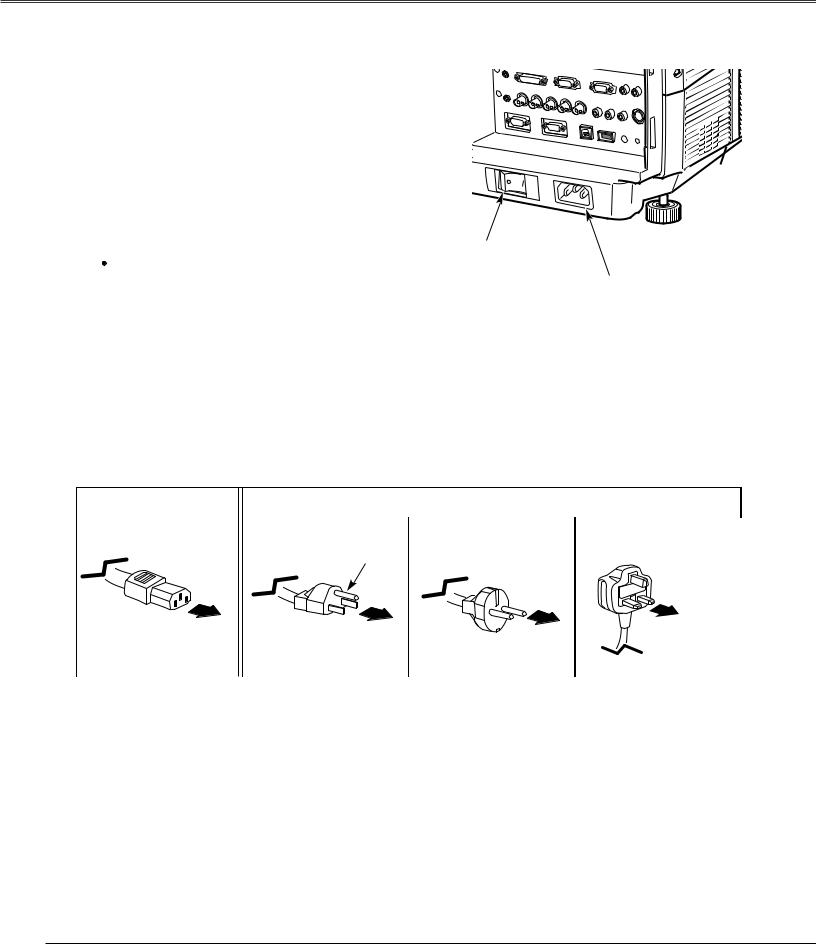
For safety, unplug AC power cord when the projector is not in use. When this projector is connected to an outlet with AC power cord and the Main On/Off switch is on, the projector is in stand-by mode and consumes a little electric power.
Main On/Off switch
AC power socket
Connect AC Power Cord (supplied) to this socket. AC outlet must be near this equipment and must be easily accessible.
NOTE ON POWER CORD
AC Power Cord must meet requirement of the country where you use the projector.
Confirm an AC plug type with the chart below and a proper AC power cord must be used. If the supplied AC Power Cord does not match your AC outlet, contact your sales dealer.
Projector side |
|
|
|
|
AC Outlet side |
|
|
|
|
|
|
|
|
|
|
|
|
|
|
|
|
|
|
|
||
|
For the U.S.A. and Canada |
|
For Continental Europe |
|
For the U.K. |
|
||
|
|
|
|
|
|
|
|
|
|
|
|
|
|
|
|
|
|
|
|
Ground |
|
|
|
|
||
To POWER CORD |
|
|
|
|
|
To the AC Outlet. |
|
To the AC Outlet. |
|
|
|||
CONNECTOR on a |
|
|
|
|
(200 - 240 V AC) |
|
|
(120 V AC) |
|
To the AC Outlet. |
|
||
projector. |
|
|
|
(200 - 240 V AC) |
|
|
|
|
|
|
|
||
|
|
|
|
|
|
|
|
|
|
|
|
|
|
|
|
|
|
|
|
|
20
Installation
Connection Terminals
Terminals to connect AC power cord and other equipment are located in the front part of the projector for easy setup. The terminal area is masked with the front cover to protect them from dust and others, and hide messy cable connections.
Remove and replace the front cover following the procedure below:
Pushing the button A on right side of the front cover, pull the part forward to remove the front cover.
To replace the front cover onto the projector, insert back the left part of the cover into the projector and then push the entire cover back the projector. Make sure the front cover is locked with the button A and fit on the projector.
Caution
Do not push hard or give a strong shock to the cover. It may cause damage to it.
Front cover
A
Pull this part forward with pushing button A.
Terminals
Interface Board Slots
The projector's front terminal area has two replaceable Interface board slots. The projector's functions can be extended by installing the optional interface boards into the terminal slots. A vacant slot (Input 5) is provided in your purchasing the projector.
Install or replace the optional interface boards as follows:
Remove 2 screws from an interface board installed in the projector.
Pull out the interface board by holding its handles and remove it. Then, insert another board along with the guides inside the slot to fit the socket into the inside plug. Tighten screws to secure the board.
Note:
When installing or removing the interface board, disconnect the AC power cord from the AC outlet before doing it.
Notes On Ordering or Using Optional Interface Boards:
When ordering or using the Optional Interface Boards, contact your sales dealer and tell the Model no. of your desired board (p75) and Option Control No. shown in the Information menu. (p31and 61)
Socket
Terminal board
Screws
Option Control No.
See Option Control No. in the Information menu to order any optional interface board.
Installation
21
Installation
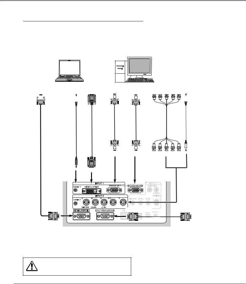
Connecting to Computer (Digital and Analog RGB)
Cables used for connection
q VGA Cable (HDB 15 pin) |
t Audio Cables (Mini Plug: stereo) |
w DVI-D Cable |
( = Not supplied with this projector.) |
e BNC Cable |
|
r Serial Cross Cable (RS-232C) |
|
|
|
PC Serial Port |
Audio Output Monitor Output |
Monitor Output |
Monitor Input |
Monitor Output |
Audio Output |
||||||||||||||||||||
|
|
|
|
|
|
|
|
|
|
|
|
|
|
|
|
|
|
|
|
|
|
|
|
|
|
|
|
|
|
|
|
|
|
|
|
|
|
|
|
|
|
|
|
|
|
|
|
|
|
|
|
|
|
|
|
|
|
|
|
|
|
|
|
|
|
|
|
|
|
|
|
|
|
|
|
|
|
|
|
|
|
|
|
|
|
|
|
|
|
|
|
|
|
|
|
|
|
|
|
|
|
|
|
|
|
|
|
|
|
|
|
|
|
|
|
|
|
|
|
|
|
|
|
|
|
|
|
|
|
|
|
|
|
|
|
|
|
|
|
|
|
|
|
|
|
|
|
|
|
|
|
|
|
|
|
|
|
|
|
|
|
|
|
|
|
|
|
|
|
|
|
|
|
|
|
|
|
|
|
|
|
r |
t |
w |
q |
q |
e |
t |
|||||
|
|
|
|
|
|
|
|
|
|
|
|
|
|
|
|
|
|
|
|
|
|
|
|
|
|
|
|
|
|
|
|
|
|
|
|
|
|
|
|
|
|
|
|
|
|
|
|
|
|
|
|
|
|
|
|
|
|
|
|
|
|
|
|
|
|
|
|
|
|
|
|
|
|
|
|
|
|
|
|
|
|
|
|
ANALOG IN ANALOG OUT |
R G B H/V V |
AUDIO 2 |
|
|
(Stereo) |
AUDIO 1 |
DIGITAL (DVI-D) |
|
(Stereo) |
||
|
SERIAL PORT IN |
|
Other Projector |
|
SERIAL PORT OUT |
SERIAL PORT IN |
||
|
r |
Note:
When connecting the cable, the power cords of both the projector and the external equipment should be disconnected from AC outlet.
22
Installation
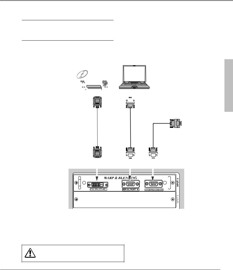
Connecting to Digital PC/AV Equipment (Warp & Blending)
Cables used for connection q DVI-D Cable
w Serial Cross Cables (RS-232C) ( = Not supplied with this projector.)
Refer to the enclosed operation manual for details in operation of the Warp & Blending feature.
|
|
|
|
|
|
|
|
|
|
|
|
|
|
|
|
|
|
|
|
|
|
|
|
|
|
|
|
|
|
|
|
|
|
|
|
|
|
|
|
|
|
|
|
|
|
|
|
|
|
|
|
|
|
|
|
|
|
|
|
|
|
|
|
|
|
|
|
|
|
|
|
|
|
|
|
|
Digital Output |
|
|
PC Serial Port |
|||||||||
|
|
|
|
|
|
|
|
|
|
|
|
|
|
|
|
|
|
|
|
|
|
|
|
|
|
|
|
|
|
|
|
|
|
|
|
|
|
|
|
|
|
|
|
|
|
|
|
|
|
|
|
|
|
|
|
|
|
|
|
|
|
|
|
|
|
|
|
|
|
|
|
|
|
|
|
|
|
|
|
|
|
|
|
|
|
|
|
|
|
Other Projector
SERIAL PORT IN
|
|
|
|
q |
|
|
|
w |
|
|
|
w |
|
|
|
|
|
|
|
|
|
|
|
|
|
|
|
|
|
|
|
|
|
|
|
|
|
|
|
|
|
|
|
|
|
|
|
|
|
|
|
|
|
|
|
|
|
|
|
|
|
|
|
|
|
|
|
|
|
|
|
|
|
|
|
|
|
|
|
|
|
|
|
|
|
|
|
|
|
|
|
|
|
|
|
|
|
|
|
|
|
|
|
|
|
|
|
|
|
|
|
|
|
|
|
|
|
|
|
|
|
|
|
|
|
|
|
DIGITAL (DVI-D)
|
|
|
|
|
|
|
|
|
|
|
|
SERIAL PORT IN |
SERIAL PORT OUT |
|
|
||||||||||
|
|
|
|
|
|
|
|
|
|
|
|
|
|
|
|
|
|
|
|
|
|
|
|
|
|
|
|
|
|
|
|
|
|
|
|
|
|
|
|
|
|
|
|
|
|
|
|
|
|
|
|
|
|
|
|
|
|
|
|
|
|
|
|
|
|
|
|
|
|
|
|
|
|
|
|
|
|
|
|
|
|
|
|
|
|
|
|
|
|
|
|
|
|
|
|
|
|
|
|
|
|
|
|
|
|
|
|
|
|
|
|
|
|
|
|
|
|
|
|
|
|
|
|
|
|
|
|
|
|
|
|
|
|
|
|
|
|
|
|
|
|
|
|
|
|
|
|
|
|
|
|
|
|
|
|
|
|
|
|
|
|
|
|
|
|
|
|
|
|
|
|
|
|
|
|
|
|
|
|
|
|
|
|
|
|
|
|
|
|
|
|
|
|
|
|
|
|
|
|
|
|
|
|
|
|
|
|
|
|
|
|
|
|
|
|
|
|
|
|
|
|
|
|
|
|
|
|
|
|
|
|
|
|
Note:
Connect digital PC/AV source to the DIGITAL (DVI- D) terminal with a DVI-D cable to adjust projected images from the computer connected to the SERIAL PORT IN terminal with Warp and Blending feature.


Note:
When connecting the cable, the power cords of both the projector and the external equipment should be disconnected from AC outlet.
Installation
23
Installation
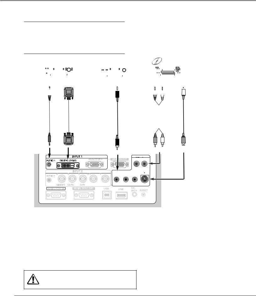
Connecting to Video Equipment (Digital and Video)
Cables used for connection q Video Cable
w S-Video Cable e DVI-D Cable
r Audio Cables (RCA x 2, Mini Plug: stereo) ( = Not supplied with this projector.)
|
|
|
|
|
|
|
|
|
|
|
|
|
|
|
|
|
|
|
|
|
|
|
|
|
|
|
|
|
|
|
|
|
|
|
|
|
|
|
|
|
|
|
|
|
|
|
|
|
|
|
|
|
|
|
|
|
|
|
|
|
|
|
|
|
|
|
|
|
|
|
|
|
|
|
|
|
|
|
|
|
|
|
|
|
|
|
|
|
|
|
|
|
|
|
|
|
|
|
|
|
|
|
|
|
|
|
|
|
|
Audio Output |
Digital Output |
|
|
|
|
|
Audio Output |
S-Video Output |
|||||||||||||
|
Video Output |
||||||||||||||||||||
(Stereo) |
(HDCP compatible) |
|
|
|
|
|
|
(R) (L) |
|
|
|
|
|||||||||
|
|
|
|
|
|
|
|
|
|
|
|
|
|
|
|
|
|
|
|
|
|
|
|
|
|
|
|
|
|
|
|
|
|
|
|
|
|
|
|
|
|
|
|
|
|
|
|
|
|
|
|
|
|
|
|
|
|
|
|
|
|
|
|
|
|
|
|
|
|
|
|
|
|
|
|
|
|
|
|
|
|
|
|
|
|
|
|
|
|
|
|
|
|
|
|
|
|
|
|
|
|
|
|
|
|
|
|
|
|
|
|
|
|
|
|
|
|
|
|
|
|
|
|
|
|
|
|
|
|
|
|
|
|
|
|
|
|
|
|
|
|
|
|
|
|
|
|
|
|
|
|
|
|
|
|
|
|
|
|
|
|
|
|
|
|
|
|
|
|
|
|
|
|
|
|
r |
|
|
|
|
e |
|
|
|
q |
|
|
r |
|
w |
|||||
|
|
|
|
|
|
|
|
|
|
|
|
|
|
|
|
|
|
|
|
|
|
|
|
|
|
|
|
|
|
|
|
|
|
|
|
|
|
|
|
|
|
|
|
|
|
|
|
|
|
|
|
|
|
|
|
|
|
|
|
AUDIO 1 |
DIGITAL (DVI-D) |
|
AUDIO |
(R) |
(L) |
S–VIDEO |
(Stereo) |
|
|||||
VIDEO |
|
|
||||
|
|
|
|
|
|
|
|
|
|
INPUT 3 |
|
|
|
|
|
|
R-AUDIO-L |
|
|
|
|
|
|
(MONO) |
|
|
|
|
|
|
S-VIDEO |
|
|
|
|
VIDEO/Y |
Cb/Pb |
Cr/Pr |
|
|
|
Note:
When connecting the cable, the power cords of both the projector and the external equipment should be disconnected from AC outlet.
24
Installation
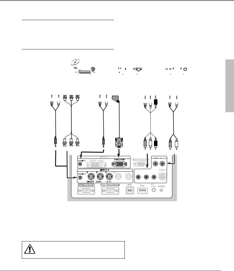
Connecting to Video Equipment (Component and RGB Scart)
Cables used for connection q BNC Cable
w Scart-VGA Cable
e Component Cable
r Audio Cables (Mini Plug (stereo) + RCA x 2, or RCA x 1) ( = Not supplied with this projector.)
|
|
|
|
|
|
|
|
|
|
|
|
|
|
|
|
|
|
|
|
|
|
|
|
|
|
|
|
|
|
|
|
|
|
|
|
|
|
|
|
|
|
|
|
|
|
|
|
|
|
|
|
|
|
|
|
|
|
|
|
|
|
|
|
|
|
|
|
|
|
|
|
|
|
|
|
|
|
|
|
|
|
|
|
|
|
|
|
|
|
|
|
|
|
|
|
|
|
|
|
|
|
|
|
|
|
|
|
|
|
|
|
|
|
|
|
|
|
|
|
|
|
|
|
|
|
|
|
|
|
|
|
|
|
|
|
|
|
|
|
|
|
|
|
|
|
|
|
|
|
|
|
|
|
|
|
|
|
|
|
|
|
|
|
|
Audio Output |
Component |
Audio Output |
RGB Scart |
Component Video Output Audio Output |
|
|||||||||||||||||||||||||||
|
(R) (L) |
Video Output |
|
|
|
(R) (L) |
21-pin Output |
|
(Y, Pb/Cb, Pr/Cr) |
|
(R) (L) |
|
||||||||||||||||||||
|
(Y, Pb/Cb, Pr/Cr) |
|
|
|
|
|
|
|
|
|
|
|
|
|
|
|
|
|
||||||||||||||
|
|
|
|
|
|
|
|
|
|
|
|
|
|
|
|
|
|
|
|
|
|
|
|
|
|
|
|
|
|
|||
|
|
|
|
|
|
|
|
|
|
|
|
|
|
|
|
|
|
|
|
|
|
|
|
|
|
|
|
|
|
|
|
|
|
|
|
|
|
|
|
|
|
|
|
|
|
|
|
|
|
|
|
|
|
|
|
|
|
|
|
|
|
|
|
|
|
|
|
|
|
|
|
|
|
|
|
|
|
|
|
|
|
|
|
|
|
|
|
|
|
|
|
|
|
|
|
|
|
|
|
|
|
|
|
|
|
|
|
|
|
|
|
|
|
|
|
|
|
|
|
|
|
|
|
|
|
|
|
|
|
|
|
|
|
|
|
|
|
|
|
|
|
|
|
|
|
|
|
|
|
|
|
|
|
|
|
|
|
|
|
|
|
|
|
|
|
|
|
|
|
|
|
|
|
|
|
|
|
|
|
|
|
|
|
|
|
|
|
|
|
|
|
|
|
|
|
|
|
r |
q |
|
|
|
|
|
r |
|
|
|
|
w |
|
|
|
e |
|
r |
|
|
|
|
|
|
|
|
|
|
|
|
|
|
|
|
|
|
|
|
|
|
|
|
|
|
|
|
|
|
|
|
|
|
|
|
|
|
|
|
|
|
|
|
|
|
|
|
|
|
|
|
|
|
|
|
|
|
|
|
|
|
|
|
|
AUDIO 1 |
|
|
|
|
|
|
AUDIO 2 |
|
|
|
(Stereo) |
|
|
|
|
|
|
Y |
Cb/Pb |
Cr/Pr |
ANALOG IN |
|
|
|
|
(L) AUDIO |
||
(Stereo) |
Y Cb/Pb |
Cr/Pr |
(R) |
|||||||
|
|
|
|
|||||||
|
|
|
|
|
|
|
INPUT 3 |
|
|
|
|
|
|
|
|
|
|
R-AUDIO-L |
|
|
|
|
|
|
|
|
|
|
(MONO) |
|
|
|
|
|
|
|
VIDEO/Y |
Cb/Pb |
Cr/Pr |
|
|
||
Installation
Note:
When connecting the cable, the power cords of both the projector and the external equipment should be disconnected from AC outlet.
25
Basic Operation
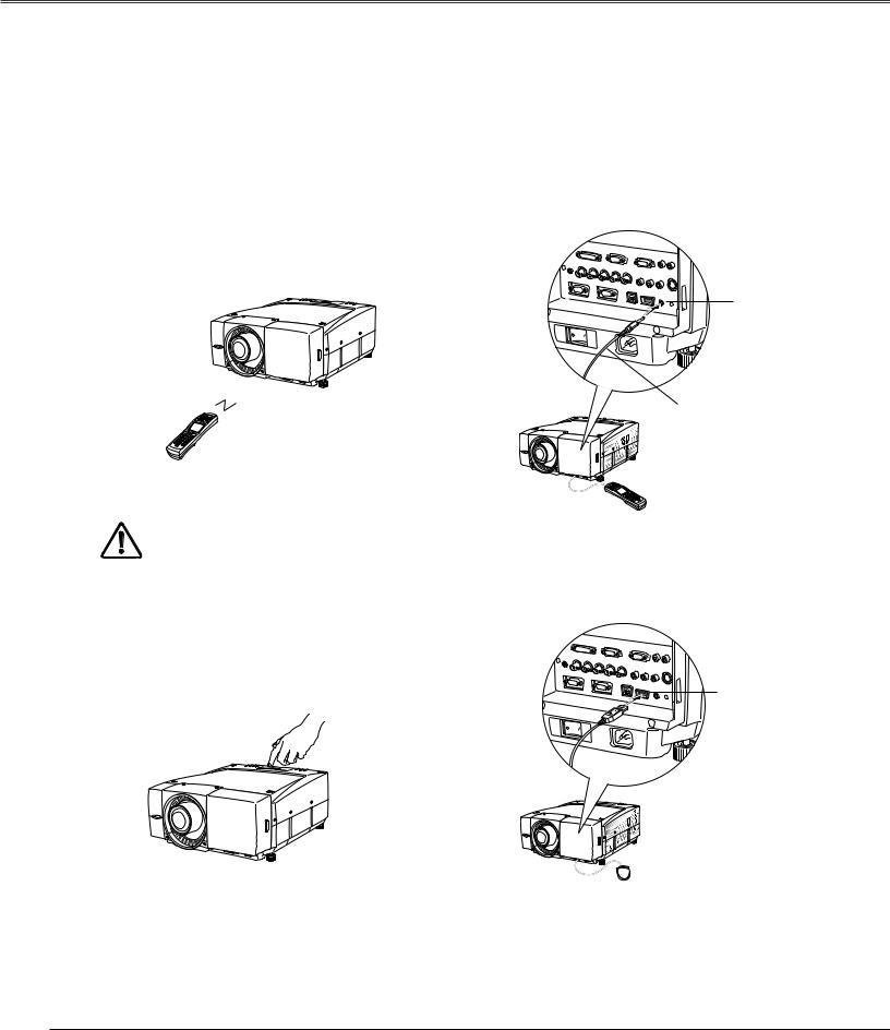
Operating the Projector
You can operate the projector with the projector's top control, the remote control or a USB mouse (not provided). The remote control is available as wireless and wired.
Operational range of the wireless remote control is within about 32.8' (10m) from the projector. Operational range differs depending on environments where the projector is used. Any obstruction to air signal between the projector and the remote control may prevent the remote control from working properly.
Wireless Remote Control Operation |
Wired Remote Control Operation |
The wireless remote control does not work when the remote control cable is connected to either the projector or the remote control. Remove the remote control cable from both of the projector and the remote control when using it as wireless.
R/C jack
Remote control cable
Connect the R/C JACK on the projector and the remote control with the remote control cable when operating the remote control as wired.
Mouse Operation
Projector Top Control Operation
USB terminal
Connect the USB terminal on the projector and a USB mouse when operating the projector's menu with the USB mouse. A mouse cursor will appear on the screen with the mouse connected.
Mouse operation offers the On-Screen Menu control only. Other operations are unavailable with the USB mouse. For details of the mouse operation, refer to page 34~35.
26
 Loading...