


 Loading...
© SANYO Electric Co., Ltd. 2007
•DLP is a registered trademark of Texas Instruments. BrilliantColor and DynamicBlack are trademarks of Texas Instruments.
•IBM is a trademark or registered trademark of International Business Machines Corporation.
•Macintosh, Mac OS X and PowerBook are trademarks of Apple, Inc., registered in the U.S. and other countries.
•Windows, Windows 98, Windows Me, Windows XP or Windows 2000 are trademarks or registered trademarks of Microsoft Corporation.
•Trademark PJLink is a trademark applied for trademark rights in Japan, the United States of America and other countries and areas.
•Other product and company names mentioned in this user's manual may be the trademarks or registered trademarks of their respective holders.
Notes
(1)The contents of this user’s manual may not be reprinted in part or whole without permission.
(2)The contents of this user’s manual are subject to change without notice.
(3)The On-Screen Menu and figures in this manual may differ slightly from the product.
(4)Great care has been taken in the preparation of this user’s manual; however, should you notice any questionable points, errors or omissions, please contact us.
(5)Notwithstanding article (3), SANYO will not be responsible for any claims on loss of profit or other matters deemed to result from using the Projector.
To the Owner
Before installing and operating the projector, read this manual thoroughly.
The projector provides many convenient features and functions. Operating the projector properly enables you to manage those features and maintains it in good condition for many years to come.
Improper operation may result in not only shortening the product life, but also malfunctions, fire hazard, or other accidents.
If your projector seems to operate improperly, read this manual again, check operations and cable connections and try the solutions in the “Troubleshooting” section in the back of this booklet. If the problem still persists, contact the dealer where you purchased the projector or the service center.
CAUTION: TO REDUCE THE RISK OF ELECTRIC SHOCK, DO NOT REMOVE COVER (OR BACK). NO USER-SERVICEABLE PARTS INSIDE EXCEPT LAMP REPLACEMENT. REFER SERVICING TO QUALIFIED SERVICE PERSONNEL.
THIS SYMBOL INDICATES THAT DANGEROUS VOLTAGE CONSTITUTING A RISK OF ELECTRIC SHOCK IS PRESENT WITHIN THIS UNIT.
THIS SYMBOL INDICATES THAT THERE
ARE IMPORTANT OPERATING AND
MAINTENANCE INSTRUCTIONS IN THE
USER’S MANUAL WITH THIS UNIT.
NOTE: This symbol and recycle system are applied only to EU countries and not applied to the countries in the other area of the world.
Your SANYO product is designed and manufactured with high quality materials and components which can be recycled and
reused.
This symbol means that electrical and electronic equipment, at their end-of-life, should be disposed of separately from your household waste.
Please dispose of this equipment at your local community waste collection/recycling center.
In the European Union there are separate collection systems for used electrical and electronic products. Please help us to conserve the environment we live in!
READ AND KEEP THIS USER’S MANUAL FOR LATER USE.
Safety Precaution
WARNING:
TO REDUCE THE RISK OF FIRE OR ELECTRIC SHOCK, DO NOT EXPOSE THIS APPLIANCE TO RAIN OR MOISTURE.
−This projector produces intense light from the projection lens. Do not stare directly into the lens as much as possible, otherwise eye damage could result. Be especially careful that children do not stare directly into the beam.
−Install the projector in a proper position. Otherwise it may result in fire hazard.
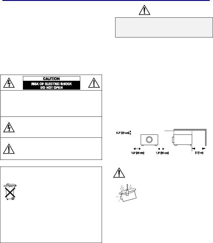
−Allowing the proper amount of space on the top, sides, and rear of the projector cabinet is critical for proper air circulation and cooling of the unit. The dimension shown here indicates the minimum space required.
If the projector is to be built into a compartment or similarly enclosed, these minimum distances must be maintained.
−Do not cover the ventilation slot on the projector. Heat build-up can reduce the service life of your projector, and can also be dangerous.
SIDE and TOP |
|
REAR |
|
|
|||||||||
|
|
|
|
|
|
|
|
|
|
|
|
|
|
|
|
|
|
|
|
|
|
|
|
|
|
|
|
|
|
|
|
|
|
|
|
|
|
|
|
|
|
|
|
|
|
|
|
|
|
|
|
|
|
|
|
|
|
|
|
|
|
|
|
|
|
|
|
|
|
|
|
|
|
|
|
|
|
|
|
|
|
|
|
−If the projector is unused for an extended time, unplug the projector from the power outlet.
CAUTION ON HANGING FROM THE CEILING
When hanging the projector from the ceiling, clean air intake vents, filters, or top of the projector periodically with a vacuum cleaner. If you leave the projector unclean for a long time, the cooling fans can be clogged with dust, and it may cause a breakdown.
DO NOT SET THE PROJECTOR IN GREASY, WET, OR CONDITIONS SUCH AS IN A KITCHEN TO PREVENT A BREAKDOWN. IF THE PROJECTOR COMES IN CONTACT WITH OIL OR CHEMICALS, IT MAY BECOME DETERIORATED.
WARNING:
Not for use in a computer room as defined in the Standard for the Protection of Electronic Computer/Data Processing Equipment, ANSI/NFPA 75.
Ne peut être utilisé dans une salle d’ordinateurs telle que définie dans la norme ANSI/NFPA 75 Standard for Protection of Electronic Computer/Data Processing Equipment.
i
Safety Instructions
All the safety and operating instructions should be read before the product is operated.
Read all of the instructions given here and retain them for later use. Unplug this projector from AC power supply before cleaning. Do not use liquid or aerosol cleaners. Use a damp cloth for cleaning.
Follow all warnings and instructions marked on the projector.
For added protection to the projector during a lightning storm, or when it is left unattended and unused for long periods of time, unplug it from the wall outlet. This will prevent damage due to lightning and power line surges.
Do not expose this unit to rain or use near water... for example, in a wet basement, near a swimming pool, etc...
Do not use attachments not recommended by the manufacturer as they may cause hazards.
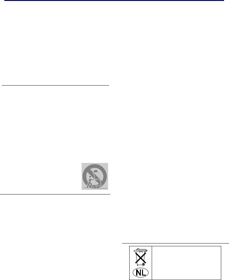
Do not place this projector on an unstable cart, stand, or table. The projector may fall, causing serious injury to a child or adult, and serious damage to the projector. Use only with a cart or stand recommended by the manufacturer, or sold with the projector. Wall or shelf mounting should follow the manufacturer’s instructions, and should use a mounting kit approved by the manufacturers.
An appliance and cart combination should be moved with care. Quick stops, excessive force, and uneven surfaces may cause the appliance and cart combination to overturn.
Slots and openings in the back and bottom of the cabinet are provided for ventilation, to ensure reliable operation of the equipment and to protect it from overheating.
The openings should never be covered with cloth or other materials, and the bottom opening should not be blocked by placing the projector on a bed, sofa, rug, or other similar surface. This projector should never be placed near or over a radiator or heat register.
This projector should not be placed in a built-in installation such as a bookcase unless proper ventilation is provided.
Never push objects of any kind into this projector through cabinet slots as they may touch dangerous voltage points or short out parts that could result in a fire or electric shock. Never spill liquid of any kind on the projector.
Do not install the projector near the ventilation duct of airconditioning equipment.
This projector should be operated only from the type of power source indicated on the marking label. If you are not sure of the type of power supplied, consult your authorized dealer or local power company.
Do not overload wall outlets and extension cords as this can result in fire or electric shock. Do not allow anything to rest on the power cord. Do not locate this projector where the cord may be damaged by persons walking on it.
Do not attempt to service this projector yourself as opening or removing covers may expose you to dangerous voltage or other hazards. Refer all servicing to qualified service personnel.
Unplug this projector from wall outlet and refer servicing to qualified service personnel under the following conditions:
a.When the power cord or plug is damaged or frayed.
b.If liquid has been spilled into the projector.
c.If the projector has been exposed to rain or water.
d.If the projector does not operate normally by following the operating instructions. Adjust only those controls that are covered by the operating instructions as improper adjustment of other controls may result in damage and will often require extensive work by a qualified technician to restore the projector to normal operation.
e.If the projector has been dropped or the cabinet has been damaged.
f.When the projector exhibits a distinct change in per- formance-this indicates a need for service.
When replacement parts are required, be sure the service technician has used replacement parts specified by the manufacturer that have the same characteristics as the original part. Unauthorized substitutions may result in fire, electric shock, or injury to persons.
Upon completion of any service or repairs to this projector, ask the service technician to perform routine safety checks to determine that the projector is in safe operating condition.
Voor de klanten in Nederland
Bij dit produkt zijn batterijen geleverd.
Wanneer dezeleeg zijn, moet u ze niet weggooien maar inleveren als KCA.
ii
Important Information
Air Circulation
Openings in the cabinet are provided for ventilation. To ensure reliable operation of the product and to protect it from overheating, these openings must not be blocked or covered.
 CAUTION
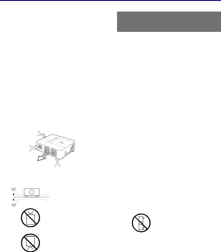
Hot air is from the exhaust vent. When using or installing the projector, the following precautions should be taken.
−Do not put any flammable objects or spray cans near the projector, hot air is exhausted from the air vents.
−Keep the exhaust vent at least 3 feet (1 m) away from any objects.
−Do not touch peripheral parts in the exhaust vents, especially screws and metallic parts. These areas will become hot while the projector is used.
−Do not put anything on the cabinet. Objects put on the cabinet will not only get damaged but may also cause a fire hazard.
Cooling fans are provided to cool down the projector. The fans’ running speed is changed according to the temperature inside the projector.
Installing the Projector in Proper Position
IMPORTANT!
Clean the Filter Regularly!!
The projector uses a lamp which generates significant heat. The cooling fans and air vents are provided to dissipate the heat by drawing air into the housing and the filter is located in the intake vents to prevent dust from getting inside of the projector.
In order to care for the projector appropriately, regular cleaning is required. Remove any dirt or dust that has accumulated on the projector and on or in the filter.
When the “Please clean filter” message is displayed, stop using the projector immediately and clean or replace the filter.
Blocking the air vents and leaving the projector uncleaned for a long time may not only damage the projector and may require costly repairs but may also cause accidents or fire.
For maintenance of the filter, refer to “Option” on page 83 and “Replacing the Filters” on pages 97 – 98.
Damages to the projector caused by using an un-cleaned filter or improper maintenance will void the warranty on the projector.
Install the projector properly. Improper installation may reduce the lamp lifetime and cause a fire hazard.
Do not tilt the projector more than 10 degrees above and below.
Do not point the projector up to project an image.
NO UPWARD
NO SIDEWAYS
Do not point the projector down to project an image.
NO DOWNWARD
Do not put the projector on either side to project an image.
iii
Compliance
Federal Communications Commission Notice
This equipment has been tested and found to comply with the limits for a Class B digital device, pursuant to Part 15 of the FCC Rules. These limits are designed to provide reasonable protection against harmful interference in a residential installation. This equipment generates, uses, and can radiate radio frequency energy and, if not installed and used in accordance with the instructions, may cause harmful interference to radio communications. However, there is no guarantee that interference will not occur in a particular installation. If this equipment does cause harmful interference to radio or television reception, which can be determined by turning the equipment off and on, the user is encouraged to try to correct the interference by one or more of the following measures:
−Reorient or relocate the receiving antenna. Increase the separation between the equipment and receiver.
−Connect the equipment into an outlet on a circuit different from that to which the receiver is connected.
−Consult the dealer or an experienced radio/TV technician for help.
Use of shielded cable is required to comply with class B limits in Subpart B of Part 15 of FCC Rules.
Do not make any changes or modifications to the equipment unless otherwise specified in the instructions. If such changes or modifications should be made, you could be required to stop operation of the equipment.
Model Number(s) |
: PDG-DWT50L |
Trade Name |
: Sanyo |
Responsible party |
: SANYO FISHER COMPANY |
Address |
: 21605 Plummer Street, Chatsworth, California 91311 U.S.A. |
Telephone No. |
: (818)998-7322 |
AC Power Cord Requirement
The AC Power Cord supplied with this projector meets the requirement for use in the country you purchased it.
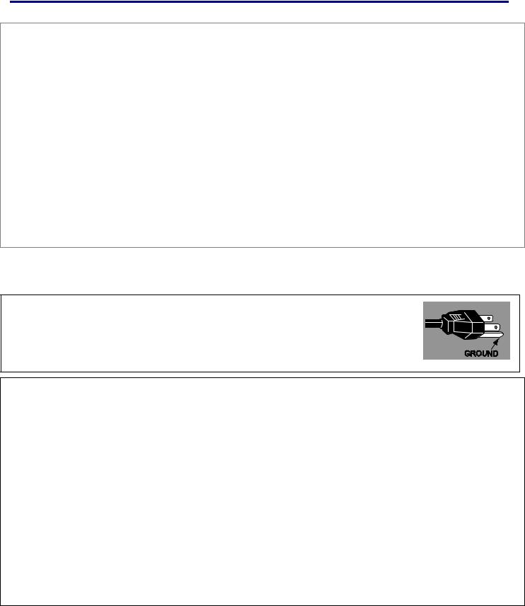
AC Power Cord for the United States and Canada:
AC Power Cord used in the United States and Canada is listed by the Underwriters Laboratories (UL) and certified by the Canadian Standard Association (CSA).
AC Power Cord has a grounding-type AC line plug. This is a safety feature to be sure that the plug will fit into the power outlet. Do not try to defeat this safety feature. Should you be unable to insert the plug into the outlet, contact your electrician.
AC Power Cord for the United Kingdom:
This cord is already fitted with a modulized plug incorporating a fuse, the value of which is indicated on the pin face of the plug. Should the fuse need to be replaced, an ASTA approved BS 1362 fuse must be used of the same rating, marked thus . If the fuse cover is
detachable, never use the plug with the cover omitted. If a replacement fuse cover is required, ensure it is of the same color as that visible on the pin face of the plug (i.e. red or orange). Fuse covers are available from the Parts Department indicated in your User Instructions. If the plug supplied is not suitable for your socket outlet, it should be cut off and destroyed. The end of the flexible cord should be suitably prepared and the correct plug fitted.
WARNING: A PLUG WITH BARED FLEXIBLE CORD IS HAZARDOUS IF ENGAGED IN A LIVE SOCKET OUTLET.
The Wires in this mains lead are colored in accordance with the following code: Green-and-yellow ············ Earth
Blue ································· Neutral Brown ······························ Live
As the colors of the wires in the mains lead of this apparatus may not correspond with the colored markings identifying the terminals in your plug proceed as follows:
The wire which is colored green-and-yellow must be connected to the terminal in the plug which is marked by the letter E or by the safety earth symbol or colored green or green-and-yellow.
The wire which is colored blue must be connected to the terminal which is marked with the letter N or colored black. The wire which is colored brown must be connected to the terminal which is marked with the letter L or colored red.
WARNING: THIS APPARATUS MUST BE EARTHED.
THE SOCKET-OUTLET SHOULD BE INSTALLED NEAR THE EQUIPMENT AND EASILY ACCESSIBLE.
iv

Table of Contents |
|
1. INTRODUCTION .................................................................................................................................................................................. |
1 |
WHAT’S IN THE BOX?.......................................................................................................................................................................... |
1 |
INTRODUCTION TO THE PROJECTOR................................................................................................................................................... |
2 |
Features you’ll enjoy:........................................................................................................................................................................ |
2 |
PART NAMES OF THE PROJECTOR ..................................................................................................................................................... |
3 |
Front-right view.................................................................................................................................................................................. |
3 |
Top view ............................................................................................................................................................................................. |
4 |
Bottom view ....................................................................................................................................................................................... |
5 |
TOP FEATURES ................................................................................................................................................................................... |
6 |
Lens Controls..................................................................................................................................................................................... |
6 |
OSD Controls and Status LEDs...................................................................................................................................................... |
7 |
TERMINAL PANEL FEATURES .............................................................................................................................................................. |
9 |
PART NAMES OF THE REMOTE CONTROL ........................................................................................................................................ |
11 |
Battery Installation .......................................................................................................................................................................... |
13 |
Operating Range for Wireless Remote Control.......................................................................................................................... |
14 |
Remote Control Precautions ......................................................................................................................................................... |
14 |
Remote Control Codes................................................................................................................................................................... |
14 |
Using the Remote Control in Wired Operation ........................................................................................................................... |
15 |
Carrying the Projector .................................................................................................................................................................... |
16 |
2. INSTALLATION AND CONNECTIONS ......................................................................................................................................... |
17 |
SETTING UP THE SCREEN AND THE PROJECTOR............................................................................................................................. |
17 |
SELECTING A LOCATION.................................................................................................................................................................... |
18 |
INSTALLING OR REMOVING THE OPTIONAL LENS ............................................................................................................................. |
19 |
Removing the Existing Lens From the Projector........................................................................................................................ |
19 |
Installing the New Lens .................................................................................................................................................................. |
20 |
Installing the New Lens Using the anti-theft screw .................................................................................................................... |
21 |
THROW DISTANCE AND SCREEN SIZE .............................................................................................................................................. |
22 |
INSTALLING THE OPTIONAL COLOR WHEEL ..................................................................................................................................... |
24 |
MAKING CONNECTIONS..................................................................................................................................................................... |
26 |
Connecting Your PC or Macintosh Computer............................................................................................................................. |
26 |
Connecting an External Monitor.................................................................................................................................................... |
28 |
Connecting Your DVD Player with Component Output............................................................................................................. |
29 |
Connecting Your VCR or Laser Disc Player ............................................................................................................................... |
30 |
CONNECTING THE SUPPLIED POWER CABLE ................................................................................................................................... |
31 |
NOTE ON THE POWER CORD ................................................................................................................................................... |
31 |
3. PROJECTING AN IMAGE (BASIC OPERATION) ....................................................................................................................... |
32 |
TURNING ON THE PROJECTOR.......................................................................................................................................................... |
32 |
Note on Startup Screen (Menu Language Select screen) ........................................................................................................ |
33 |
SELECTING AN INPUT SOURCE ......................................................................................................................................................... |
34 |
ADJUSTING THE PICTURE POSITION AND PICTURE SIZE.................................................................................................................. |
35 |
Adjusting Picture Position Manually ............................................................................................................................................. |
35 |
Lens Shift Adjustable Range ......................................................................................................................................................... |
36 |
From the Remote Control Unit ...................................................................................................................................................... |
37 |
Adjusting the Projector Level......................................................................................................................................................... |
38 |
OPTIMIZING AN RGB IMAGE AUTOMATICALLY ................................................................................................................................. |
39 |
Adjusting the Image Using AUTO PC ADJ. ................................................................................................................................ |
39 |
ADJUSTING VOLUME UP AND DOWN ................................................................................................................................................ |
40 |
TURNING OFF THE PROJECTOR ........................................................................................................................................................ |
41 |
About Direct Power Off................................................................................................................................................................... |
42 |
After Use........................................................................................................................................................................................... |
42 |
4. CONVENIENT FEATURES .............................................................................................................................................................. |
43 |
TURNING OFF THE IMAGE AND SOUND............................................................................................................................................. |
43 |
FREEZING A PICTURE........................................................................................................................................................................ |
43 |
ADJUSTING THE FOCUS/ZOOM MANUALLY....................................................................................................................................... |
44 |
v

|
Table of Contents |
Adjusting by Using the OSD Control Panel................................................................................................................................. |
44 |
CHANGING LAMP MODE .................................................................................................................................................................... |
45 |
Changing Lamp Mode by Using the Projector's OSD Control Panel ...................................................................................... |
45 |
Changing Lamp Mode by Using the Remote Control ................................................................................................................ |
46 |
GETTING INFORMATION..................................................................................................................................................................... |
47 |
ADJUSTING POSITION/TOTAL DOTS/FINE SYNC .............................................................................................................................. |
48 |
Adjusting Position/Total Dots/Fine Sync by using the OSD Control Panel ............................................................................ |
48 |
Correcting Keystone by Using the Remote Control ................................................................................................................... |
49 |
PREVENTING THE UNAUTHORIZED USE OF THE PROJECTOR .......................................................................................................... |
51 |
Locking the Projector...................................................................................................................................................................... |
51 |
Unlocking the Projector .................................................................................................................................................................. |
53 |
USING THE PHYSICAL LOCK.............................................................................................................................................................. |
54 |
Using the Kensington Lock............................................................................................................................................................ |
54 |
Using the Security Chain Lock...................................................................................................................................................... |
54 |
5. USING ON-SCREEN DISPLAY....................................................................................................................................................... |
55 |
USING THE MENUS............................................................................................................................................................................ |
55 |
Navigating the OSD ........................................................................................................................................................................ |
55 |
MENU TREE....................................................................................................................................................................................... |
57 |
MENU ELEMENTS .............................................................................................................................................................................. |
59 |
SOURCE MENU DESCRIPTIONS AND FUNCTIONS ............................................................................................................................. |
60 |
ADJUST MENU DESCRIPTIONS AND FUNCTIONS .............................................................................................................................. |
61 |
Image menu ..................................................................................................................................................................................... |
61 |
Image options menu ....................................................................................................................................................................... |
62 |
Video menu...................................................................................................................................................................................... |
64 |
DETAIL SETTINGS MENU DESCRIPTIONS AND FUNCTIONS .............................................................................................................. |
67 |
Basic ................................................................................................................................................................................................. |
67 |
White balance.................................................................................................................................................................................. |
69 |
Color correction ............................................................................................................................................................................... |
70 |
SETTING MENU DESCRIPTIONS AND FUNCTIONS............................................................................................................................. |
71 |
Basic ................................................................................................................................................................................................. |
71 |
Installation ........................................................................................................................................................................................ |
75 |
Network setting................................................................................................................................................................................ |
82 |
Option ............................................................................................................................................................................................... |
83 |
INFORMATION MENU DESCRIPTIONS AND FUNCTIONS..................................................................................................................... |
89 |
Usage time ....................................................................................................................................................................................... |
89 |
Input .................................................................................................................................................................................................. |
90 |
Network............................................................................................................................................................................................. |
91 |
Version.............................................................................................................................................................................................. |
92 |
RESET MENU DESCRIPTIONS AND FUNCTIONS................................................................................................................................ |
93 |
6. MAINTENANCE ................................................................................................................................................................................. |
94 |
CLEANING THE PROJECTOR .............................................................................................................................................................. |
94 |
Cleaning the Cabinet ...................................................................................................................................................................... |
94 |
Cleaning the Lens ........................................................................................................................................................................... |
94 |
Cleaning the Filters......................................................................................................................................................................... |
95 |
REPLACING CONSUMABLE PARTS .................................................................................................................................................... |
97 |
Replacing the Filters....................................................................................................................................................................... |
97 |
Replacing the Lamps...................................................................................................................................................................... |
99 |
Resetting the Lamp Time Counter.............................................................................................................................................. |
101 |
Ordering a Replacement Lamp................................................................................................................................................... |
101 |
7. APPENDIX ........................................................................................................................................................................................ |
102 |
TROUBLESHOOTING ........................................................................................................................................................................ |
102 |
Indicator Messages....................................................................................................................................................................... |
102 |
Common Problems and Solutions.............................................................................................................................................. |
104 |
Tips for Troubleshooting .............................................................................................................................................................. |
104 |
IMAGE PROBLEMS ........................................................................................................................................................................... |
105 |
vi

Table of Contents |
|
Lamp Problems ............................................................................................................................................................................. |
105 |
Remote Control Problems ........................................................................................................................................................... |
106 |
Audio Problems ............................................................................................................................................................................. |
106 |
HAVING THE PROJECTOR SERVICED .............................................................................................................................................. |
106 |
8. SPECIFICATIONS ........................................................................................................................................................................... |
107 |
PROJECTOR SPECIFICATIONS......................................................................................................................................................... |
107 |
Optical Specifications ................................................................................................................................................................... |
107 |
Electrical Specifications ............................................................................................................................................................... |
108 |
Mechanical Specifications ........................................................................................................................................................... |
109 |
Environmental Considerations .................................................................................................................................................... |
109 |
Regulations .................................................................................................................................................................................... |
109 |
Optional Parts................................................................................................................................................................................ |
110 |
CABINET DIMENSIONS..................................................................................................................................................................... |
111 |
PIN ASSIGNMENTS OF MINI D-SUB 15 PIN INPUT CONNECTOR.................................................................................................... |
112 |
COMPATIBLE INPUT SIGNAL LIST.................................................................................................................................................... |
113 |
PC CONTROL CODES AND CABLE CONNECTIONS......................................................................................................................... |
115 |
Functional Execution Command Table...................................................................................................................................... |
115 |
Status Read Command Table..................................................................................................................................................... |
116 |
SCREEN TRIGGER ........................................................................................................................................................................... |
117 |
OPERATION USING HTTP BROWSER............................................................................................................................................. |
118 |
Overview......................................................................................................................................................................................... |
118 |
Preparation Before Use................................................................................................................................................................ |
118 |
Handling of the Address for Operation by Using a Browser................................................................................................... |
118 |
Configuring Network Settings...................................................................................................................................................... |
119 |
Structure of the HTTP Server...................................................................................................................................................... |
121 |
15 PIN GPIO CONTROL ................................................................................................................................................................. |
123 |
9. TROUBLESHOOTING CHECK LIST ........................................................................................................................................... |
124 |
vii
1. Introduction
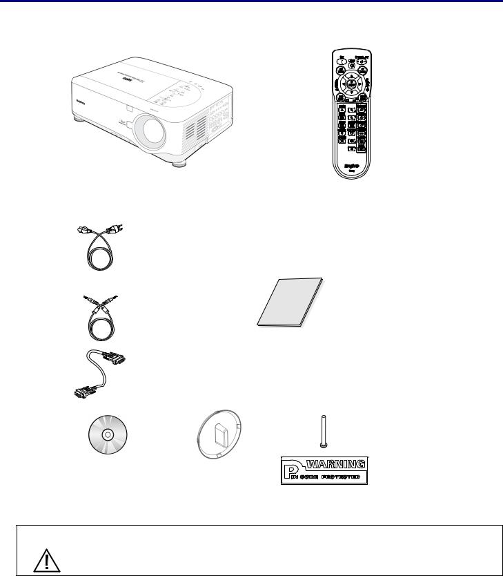
What’s in the Box?
Carefully unpack the projector and check that the following items are included:
PDG-DWT50L Projector |
Remote Control |
|
(with Two AA alkaline batteries) |
Power Cable |
|
(3.6m/11.8 ft.) |
|
→ For North |
|
America, |
|
Europe and |
|
the UK |
|
Remote Cable |
Quick Start Guide |
|
|
(10m/33ft) |
|
VGA Cable
|
|
Anti-Theft |
|
|
Screw for lens |
|
|
x 1 |
|
|
Security |
CD-ROM |
Lens Hole Cap |
Sticker |
(This User’s manual) |
(Installed) |
|
Contact your dealer immediately if any items are missing, appear damaged, or if the unit does not work.
CAUTION
Avoid using the projector in dusty environments.
1
1. Introduction
Introduction to the Projector
Features you’ll enjoy:
DLP projector with high resolution
The combination of BrilliantColor™ and a six-segment color wheel (optional) offer a more true color reproduction.
Installation Flexibility
This projector has many useful functions such as powered lens shifting, ceiling and rear projection, variety of extensive optional powered lens with bayonet mount with release button, etc.
Multiple Interface Terminals
The projector has several interface terminals that can support various types of equipment and signals.
Dual Lamp Control System
The two-lamp control system offers high brightness, maintained lamp life and energy savings along with redundancy. The lamp control function offers brightness of the lamp can be selected. The power management function also reduces power consumption and maintains lamp life.
Simple Computer System Setting
The projector has the Multi-scan system to conform to almost all computer output signals quickly. Up to UXGA resolution can be accepted.
Security Function
The Security function helps you to ensure security of the projector. With the Key lock function, you can lock the operation on the top control. PIN code lock functions prevent unauthorized use of the projector.
Multilanguage Menu Display
Operation menu is available in 8 languages: English, German, French, Italian, Spanish, Swedish, Chinese, and Japanese.
Multi-use Remote Control
Use the remote control as wired or wireless. Eight remote control codes are available.
3W + 3W Stereo Speaker
Built in 3W x 2 speakers are provided.
Helpful Maintenance Functions
The lamp and filter maintenance functions provide for better and proper maintenance of the projector. Easy maintenance cover is provided for lamp and color wheel replacement.
Direct Power Off and On Start
The Direct Power Off function allows the projector to be turned off (even when projecting an image) using a power strip equipped with a switch and a breaker. The On Start function allows the projector to be turned on by supplied AC power.
Note:
Before using Direct Power Off, be sure to allow at least 20 minutes immediately after turning on the projector and starting to display an image. Also, the power cord can be removed immediately after turning off the projector. On Start manual may differ slightly from the product.
On Start eliminates the need to always use the POWER (ON/STANDBY) button on the remote control or projector cabinet.
2
1. Introduction
Part Names of the Projector
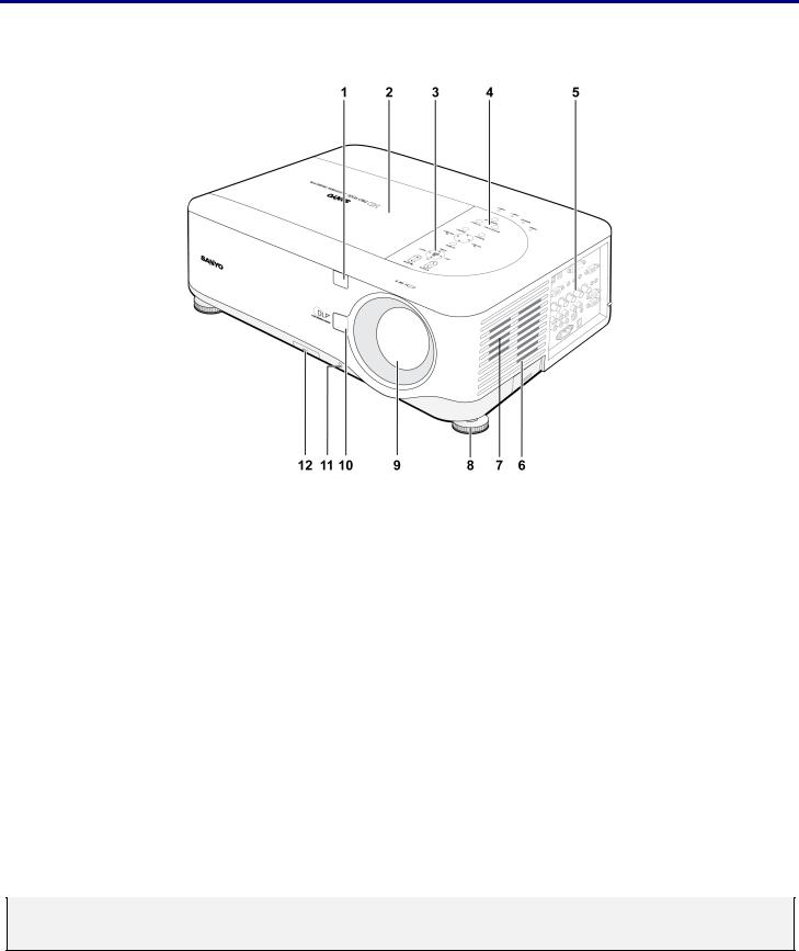
Front-right view
|
|
|
|
|
|
|
|
|
|
|
|
|
ITEM |
|
|
LABEL |
|
|
DESCRIPTION |
|
|
SEE PAGE: |
|
|
|
|
|
|
|
|
|
|
|
|
|
|
1. |
|
|
IR receiver |
|
|
Receiver for IR signal from remote control |
|
11 |
|
|
|
2. |
|
|
Lamp cover |
|
|
Remove cover to replace lamp or color wheel |
|
99 |
|
|
|
3. |
|
|
Lens control panel |
|
|
See Lens Controls |
|
6 |
|
|
|
|
|
|
|
|
|
|
|
|
|
|
|
4. |
|
|
OSD control panel |
|
|
See OSD Controls and Status LEDS |
|
7 |
|
|
|
|
|
|
|
|
|
|
|
|
|
|
|
5. |
|
|
I/O connector panel |
|
|
Connect various input devices |
|
9 |
|
|
|
6. |
|
|
Intake vent |
|
|
Lamp cooling vent – do not obstruct |
|
|
— |
|
|
7. |
|
|
Speakers |
|
|
Built-in stereo speakers |
|
|
— |
|
|
8. |
|
|
Height adjuster |
|
|
Adjusts level of projector |
|
5 |
|
|
|
9. |
|
|
Lens |
|
|
Remove lens cap before use |
|
|
— |
|
|
10. |
|
|
Lens release button |
|
|
Press the release button before removing the lens |
|
|
— |
|
|
|
|
|
|
|
|
|
|
|
|
|
|
11. |
|
|
Anti-Theft screw |
|
|
Prevent theft of the lens |
|
|
— |
|
|
12. |
|
|
Intake vent and front |
|
|
Keeps the front fan free of dust |
|
95 |
|
|
|
|
|
|
|
– clean regularly for optimum performance |
|
|
||||
|
|
|
filter |
|
|
|
|
||||
|
|
|
|
|
|
– do not obstruct |
|
|
|
|
|
|
|
|
|
|
|
|
|
|
|
|
|
Important:
Grill openings on the projector allow for good air circulation, which keeps the projector lamp cool. Do not obstruct any of the grill openings.
3
1. Introduction
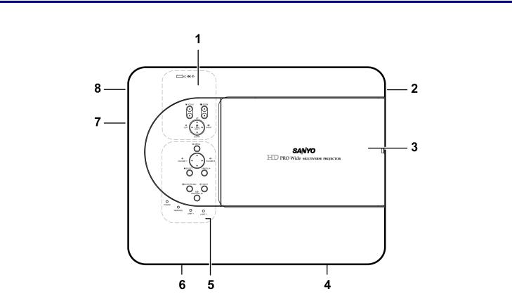
Top view
|
|
|
|
|
|
|
|
|
|
|
|
|
ITEM |
|
|
LABEL |
|
|
DESCRIPTION |
|
|
SEE PAGE: |
|
|
|
|
|
|
|
|
|
|
|
|
|
|
1. |
|
|
Lens control panel |
|
|
See Lens Controls |
|
6 |
|
|
|
|
|
|
|
|
|
|
|
|
|
|
|
2. |
|
|
Right-hand speaker |
|
|
Right-hand speaker |
|
|
— |
|
|
|
|
|
|
|
|
|
|
|
|
|
|
3. |
|
|
Lamp cover |
|
|
Remove cover to replace lamp or color wheel |
|
99 |
|
|
|
|
|
|
|
|
|
|
|
|
|
|
|
4. |
|
|
Exhaust vent |
|
|
Exhaust vent – do not obstruct |
|
|
— |
|
|
|
|
|
|
|
|
|
|
|
|
|
|
5. |
|
|
OSD control panel |
|
|
See OSD Controls and Status LEDS |
|
7 |
|
|
|
|
|
|
|
|
|
|
|
|
|
|
|
6. |
|
|
Rear intake vent |
|
|
Rear cooling intake – do not obstruct |
|
|
— |
|
|
|
|
|
|
|
|
|
|
|
|
|
|
7. |
|
|
Left intake vent |
|
|
Left-hand cooling intake – do not obstruct |
|
|
— |
|
|
|
|
|
|
|
|
|
|
|
|
|
|
8. |
|
|
Left-hand speaker |
|
|
Left-hand speaker |
|
|
— |
|
|
|
|
|
|
|
|
|
|
|
|
|
4
1. Introduction
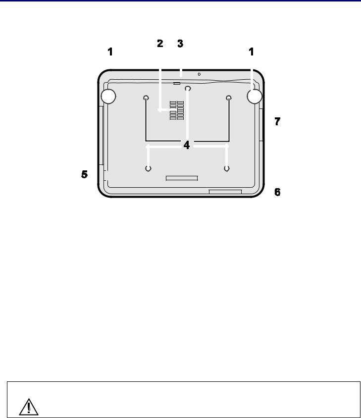
Bottom view
|
|
|
|
|
|
|
|
|
|
|
|
|
|
|
|
|
|
|
|
|
|
|
|
|
|
|
|
|
|
|
|
|
|
|
|
|
|
|
|
|
|
|
|
|
|
|
|
|
|
|
|
|
|
|
|
|
|
|
|
|
|
|
|
|
|
|
|
|
|
|
|
|
|
|
|
|
|
|
|
|
|
|
|
|
|
|
|
|
|
|
|
|
|
|
|
|
|
|
|
|
|
|
|
|
|
|
|
|
|
|
|
|
|
|
|
|
|
|
|
|
|
|
|
|
|
|
|
|
|
|
|
|
|
|
|
|
|
|
|
|
|
|
|
|
|
|
|
|
|
|
|
|
|
|
|
|
|
|
|
|
|
|
|
|
|
|
|
|
|
|
|
|
|
|
|
|
|
|
|
|
|
|
|
|
|
|
|
|
|
|
|
|
|
|
|
|
|
|
|
|
|
|
|
|
|
|
|
|
|
|
|
|
|
|
|
|
|
|
|
|
|
|
|
|
|
|
|
|
|
|
|
|
|
|
|
|
|
|
|
|
|
|
|
|
|
|
|
|
|
|
|
|
|
|
|
|
|
|
|
|
|
|
|
|
|
|
|
|
|
|
|
|
|
|
|
|
|
|
|
|
|
|
|
|
|
|
|
|
|
|
|
|
|
|
|
|
|
|
|
|
|
|
|
|
|
|
|
|
|
|
|
|
|
|
|
|
|
|
|
|
|
|
|
|
|
|
|
|
|
|
|
|
|
|
|
|
|
|
|
|
|
|
|
|
|
|
|
|
|
|
|
|
|
|
|
|
|
|
|
|
|
|
|
|
|
|
|
|
|
|
|
|
|
|
|
|
|
|
|
|
|
|
|
|
|
|
|
|
|
|
|
|
|
|
|
|
|
|
|
|
|
|
|
|
|
|
|
|
|
|
|
|
|
|
|
|
|
|
|
|
|
|
|
|
|
|
|
|
|
|
|
|
|
|
|
|
|
|
|
|
|
|
|
|
|
|
|
|
|
|
|
|
|
|
|
|
|
|
|
ITEM |
|
|
LABEL |
|
|
|
|
|
|
|
DESCRIPTION |
|
|
SEE PAGES: |
|
||||||||||
|
|
|
|
|
|
|
|
|
|
|
|
|||||||||||||||
|
1. |
|
|
Height adjusters |
|
Adjust projection height |
|
38 |
|
|||||||||||||||||
|
|
|
|
|
|
|
|
|
|
|
|
|
||||||||||||||
|
2. |
|
|
Intake vent |
|
Color wheel cooling vent – do not obstruct |
|
|
— |
|
||||||||||||||||
|
|
|
|
|
|
|
|
|
|
|
|
|
|
|||||||||||||
|
3. |
|
|
Front filter |
|
Keep the fan free of dust – clean regularly for optimum perform- |
|
95 |
|
|||||||||||||||||
|
|
|
|
ance |
|
|
||||||||||||||||||||
|
|
|
|
|
|
|
|
|
|
|
||||||||||||||||
|
|
|
|
|
|
|
|
|
|
|
|
|
|
|||||||||||||
|
4. |
|
|
Ceiling support holes |
|
Contact your dealer for information on mounting the projector on |
|
|
— |
|
||||||||||||||||
|
|
|
|
a ceiling |
|
|
|
|||||||||||||||||||
|
|
|
|
|
|
|
|
|
|
|
||||||||||||||||
|
|
|
|
|
|
|
|
|
|
|
|
|
|
|
|
|
|
|
|
|
|
|
|
|
|
|
|
5. |
|
|
Security chain |
|
Attach anti-theft device – see Using the Physical Lock |
|
54 |
|
|||||||||||||||||
|
|
|
opening |
|
|
|
||||||||||||||||||||
|
|
|
|
|
|
|
|
|
|
|
|
|
|
|
|
|
|
|
|
|
|
|
|
|
||
|
|
|
|
|
|
|
|
|
|
|
|
|
|
|
|
|
|
|
|
|
|
|
|
|
|
|
|
6. |
|
|
Rear filter |
|
Keep the fans free of dust – clean regularly for optimum per- |
|
95 |
|
|||||||||||||||||
|
|
|
|
|
|
|
|
|
||||||||||||||||||
|
7. |
|
|
Side filter |
|
formance |
|
|
||||||||||||||||||
|
|
|
|
|
|
|
|
|||||||||||||||||||
|
|
|
|
|
|
|
|
|
|
|
|
|
|
|
|
|
|
|
|
|
|
|
|
|||
|
|
|
|
|
|
|
|
|
|
|
|
|
|
|
|
|
|
|
|
|
|
|
|
|
|
|
CAUTION With ceiling installation, use approved mounting hardware & M4 screws; maximum depth of screw: 12 mm; distance from ceiling/ wall: 20 cm (0.7 feet) for proper ventilation; distance from fluorescent lamps: at least 1 m (3 feet) front and back of the projector. For permanent installations, follow local codes.
5
1. Introduction
Top Features
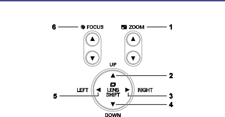
Lens Controls
|
|
|
|
|
|
|
|
|
|
|
|
|
ITEM |
|
|
LABEL |
|
|
DESCRIPTION |
|
|
SEE PAGE: |
|
|
|
|
|
|
|
|
|
|
|
|
|
|
1. |
|
|
ZOOM |
|
|
Increase/decrease projected image size |
|
44 |
|
|
|
|
|
|
|
|
|
|
|
|
|
|
|
2. |
|
|
UP CURSOR |
|
|
|
|
|
|
|
|
|
|
|
|
|
|
|
|
|
|
|
|
3. |
|
|
RIGHT CURSOR |
|
|
Move image left, right, up, or down |
|
|
|
|
|
|
|
|
|
|
|
|
|
|
|
|
|
4. |
|
|
DOWN CURSOR |
|
|
|
|
|
|
|
|
|
|
|
|
|
|
|
|
|
||
|
|
|
|
|
|
|
|
|
|
|
|
|
5. |
|
|
LEFT CURSOR |
|
|
|
|
|
|
|
|
|
|
|
|
|
|
|
|
|
||
|
6. |
|
|
FOCUS |
|
|
Focus the projected image |
|
44 |
|
|
|
|
|
|
|
|
|
|
|
|
|
|
6
1. Introduction
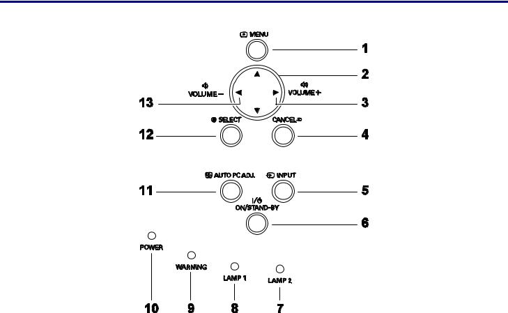
OSD Controls and Status LEDs
|
|
|
|
|
|
|
|
|
|
|
|
|
ITEM |
|
|
LABEL |
|
|
DESCRIPTION |
|
|
SEE PAGE: |
|
|
|
|
|
|
|
|
|
|
|
|
|
|
1. |
|
|
MENU |
|
|
Open / Close the OSD |
|
55 |
|
|
|
|
|
|
|
|
|
|
|
|
|
|
|
2. |
|
|
UP/ DOWN/ LEFT/ |
|
|
Navigate and change settings in the OSD |
|
55 |
|
|
|
|
|
RIGHT BUTTONS |
|
|
|
|
||||
|
|
|
|
|
|
|
|
|
|
|
|
|
|
|
|
|
|
|
|
|
|
|
|
|
3. |
|
|
RIGHT CURSOR/ |
|
|
Increase volume |
|
40 |
|
|
|
|
|
VOLUME |
|
|
|
|
||||
|
|
|
|
INCREASE |
|
|
|
|
|
|
|
|
|
|
|
|
|
|
|
|
|
|
|
|
4. |
|
|
CANCEL |
|
|
Exit the On-Screen Display (OSD) |
|
55 |
|
|
|
|
|
|
|
|
|
|
|
|
|
|
|
5. |
|
|
INPUT |
|
|
Change or select the input device |
|
34 |
|
|
|
|
|
|
|
|
|
|
|
|
|
|
|
6. |
|
|
|
|
|
Turn the projector on or off (main power switch must be turned |
|
32 |
|
|
|
|
|
ON/STAND-BY |
|
|
on first). |
|
|
|||
|
|
|
|
|
|
|
Press to place the projector in standby mode. |
|
|
|
|
|
|
|
|
|
|
|
|
|
|
|
|
|
7. |
|
|
LAMP 2 (LED) |
|
|
See Indicator Messages |
|
102 |
|
|
|
|
|
|
|
|
|
|
|
|
|
|
7

1. Introduction
|
|
|
|
|
|
|
|
|
|
|
|
|
ITEM |
|
|
LABEL |
|
|
DESCRIPTION |
|
|
SEE PAGE: |
|
|
|
|
|
|
|
|
|
|
|
|
|
|
8. |
|
|
LAMP 1 (LED) |
|
|
See Indicator Messages |
|
102 |
|
|
|
|
|
|
|
|
|
|
|
|
|
|
|
9. |
|
|
WARNING (LED) |
|
|
See Indicator Messages |
|
102 |
|
|
|
|
|
|
|
|
|
|
|
|
|
|
|
10. |
|
|
POWER (LED) |
|
|
See Indicator Messages |
|
102 |
|
|
|
|
|
|
|
|
|
|
|
|
|
|
|
11. |
|
|
AUTO PC ADJ. |
|
|
Optimize image size, position, and resolution |
|
39 |
|
|
|
|
|
|
|
|
|
|
|
|
|
|
|
12. |
|
|
SELECT |
|
|
Select or change settings in the OSD |
|
55 |
|
|
|
|
|
|
|
|
|
|
|
|
|
|
|
13. |
|
|
LEFT |
|
|
|
|
40 |
|
|
|
|
|
CURSOR/VOLUME |
|
|
Decrease volume |
|
|
|||
|
|
|
|
DECREASE |
|
|
|
|
|
|
|
|
|
|
|
|
|
|
|
|
|
|
|
8
1. Introduction
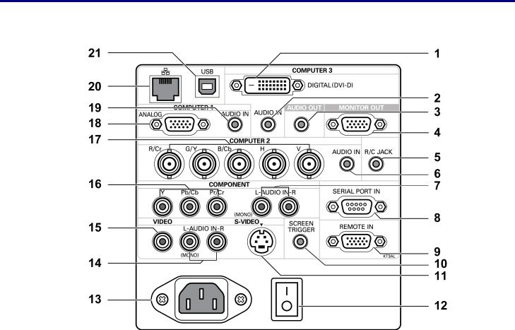
r Terminal Panel Features
|
|
|
|
|
|
|
|
|
|
|
|
|
ITEM |
|
|
LABEL |
|
|
DESCRIPTION |
|
|
SEE PAGE: |
|
|
|
|
|
|
|
|
|
|
|
|
|
|
1. |
|
|
COMPUTER 3 IN |
|
|
Connect the DVI-D cable (not supplied) from a computer |
|
26 |
|
|
|
|
|
|
|
|
|
|
|
|
|
|
|
2. |
|
|
AUDIO IN |
|
|
Connect the audio cable (not supplied) from the input device |
|
|
— |
|
|
|
|
(COMPUTER 3) |
|
|
|
|
|
|||
|
|
|
|
|
|
|
|
|
|
|
|
|
|
|
|
|
|
|
|
|
|
|
|
|
3. |
|
|
AUDIO OUT |
|
|
Audio loop-thru |
|
|
— |
|
|
|
|
|
|
|
|
|
|
|
|
|
|
4. |
|
|
MONITOR OUT |
|
|
Connect to a monitor |
|
|
— |
|
|
|
|
|
|
|
|
|
|
|
|
|
|
5. |
|
|
R/C JACK |
|
|
Connect the remote to the projector |
|
15 |
|
|
|
|
|
|
|
|
|
|
|
|
|
|
|
6. |
|
|
AUDIO IN |
|
|
Connect the audio cable (not supplied) from the input device |
|
|
— |
|
|
|
|
(COMPUTER 2) |
|
|
|
|
|
|||
|
|
|
|
|
|
|
|
|
|
|
|
|
|
|
|
|
|
|
|
|
|
|
|
|
7. |
|
|
AUDIO IN |
|
|
Connect an RCA audio cables (not supplied) from the input de- |
|
|
— |
|
|
|
|
[L(MONO)/R] |
|
|
|
|
|
|||
|
|
|
|
|
vice right and left channels |
|
|
|
|||
|
|
|
|
(COMPONENT) |
|
|
|
|
|
|
|
|
|
|
|
|
|
|
|
|
|
|
|
|
|
|
|
|
|
|
|
|
|
|
|
|
8. |
|
|
SERIAL PORT IN |
|
|
Installation control |
|
115 |
|
|
|
|
|
|
|
|
|
|
|
|
|
|
|
9. |
|
|
REMOTE IN |
|
|
For external control |
|
123 |
|
|
|
|
|
|
|
|
|
|
|
|
|
|
9

1. Introduction
|
|
|
|
|
|
|
|
|
|
|
|
|
ITEM |
|
|
LABEL |
|
|
DESCRIPTION |
|
|
SEE PAGE: |
|
|
|
|
|
|
|
|
|
|
|
|
|
|
|
|
|
|
|
|
When connected to the screen through a commercially available |
|
|
|
|
|
10. |
|
|
SCREEN |
|
|
cable, the screen deploys automatically on start up of the projec- |
|
117 |
|
|
|
|
|
TRIGGER |
|
|
tor. The screen retracts when the projector is powered off |
|
|
|||
|
|
|
|
|
|
|
|
|
|
||
|
|
|
|
|
|
|
(see notes below) |
|
|
|
|
|
|
|
|
|
|
|
|
|
|
|
|
|
11. |
|
|
S-VIDEO |
|
|
Connect a commercially available S-video cable from a video |
|
30 |
|
|
|
|
|
|
|
device |
|
|
||||
|
|
|
|
|
|
|
|
|
|
|
|
|
|
|
|
|
|
|
|
|
|
|
|
|
12. |
|
|
POWER SWITCH |
|
|
Turn on/off the projector |
|
32,41 |
|
|
|
|
|
|
|
|
|
|
|
|
|
|
|
13. |
|
|
AC IN |
|
|
Connect the supplied power cable |
|
31 |
|
|
|
|
|
|
|
|
|
|
|
|
|
|
|
14. |
|
|
AUDIO IN |
|
|
Connect RCA audio cables (not supplied) from the input device |
|
|
— |
|
|
|
|
[L(MONO)/R] |
|
|
right and left channels. This audio jack is shared with S-Video |
|
|
|
||
|
|
|
|
(VIDEO) |
|
|
input. |
|
|
|
|
|
|
|
|
|
|
|
|
|
|
|
|
|
15. |
|
|
VIDEO IN |
|
|
Connect a composite video cable (not supplied) from a video de- |
|
30 |
|
|
|
|
|
|
|
vice to the yellow RCA jack |
|
|
||||
|
|
|
|
|
|
|
|
|
|
|
|
|
|
|
|
|
|
|
|
|
|
|
|
|
16. |
|
|
COMPONENT IN |
|
|
Connect a component video enabled device |
|
29 |
|
|
|
|
|
(Y, Cb/Pb, Cr/Pr) |
|
|
|
|
||||
|
|
|
|
|
|
|
|
|
|
|
|
|
|
|
|
|
|
|
|
|
|
|
|
|
17. |
|
|
COMPUTER 2 IN |
|
|
Connect RGBHV or Component signal from computer or com- |
|
26 |
|
|
|
|
|
(R/Cr, G/Y, B/Cb, |
|
|
|
|
||||
|
|
|
|
|
ponent video enabled device |
|
|
||||
|
|
|
|
H, V) |
|
|
|
|
|
|
|
|
|
|
|
|
|
|
|
|
|
|
|
|
|
|
|
|
|
|
|
|
|
|
|
|
18. |
|
|
COMPUTER 1 IN |
|
|
Connect a VGA cable (supplied) from a computer |
|
26 |
|
|
|
|
|
|
|
|
|
|
|
|
|
|
|
19. |
|
|
AUDIO IN |
|
|
Connect the audio cable (not supplied) from the input device |
|
|
— |
|
|
|
|
(COMPUTER 1) |
|
|
|
|
|
|||
|
|
|
|
|
|
|
|
|
|
|
|
|
|
|
|
|
|
|
|
|
|
|
|
|
20. |
|
|
LAN |
|
|
Connect a LAN cable (not supplied) from a computer |
|
|
— |
|
|
|
|
|
|
|
|
|
|
|
|
|
|
21. |
|
|
SERVICE |
|
|
Connect the USB cable (not supplied) from a computer. For ser- |
|
|
— |
|
|
|
|
|
|
vice personnel only. |
|
|
|
|||
|
|
|
|
|
|
|
|
|
|
|
|
|
|
|
|
|
|
|
|
|
|
|
|
Note:
To use this feature, you must turn on the Screen Trigger function on the OSD. Screen controllers are supplied and supported by screen manufacturers.
Do not use this jack for anything other than intended use. Connecting the wired remote control to the Trigger mini jack causes damage to the remote control.
10
1. Introduction
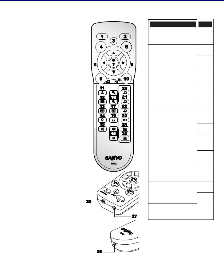
Part Names of the Remote Control
|
|
|
|
|
|
|
ITEM |
|
|
LABEL |
|
|
|
|
|
|
|
|
1. |
|
|
ON |
|
|
|
|
|
|
|
|
2. |
|
|
STAND-BY |
|
|
|
|
|
|
|
|
3. |
|
|
LIGHT |
|
|
|
|
Illuminate the remote panel. |
|
|
|
|
|
|
|
|
|
|
|
|
|
|
|
4. |
|
|
MENU |
|
|
|
|
Open or close the on-Screen |
|
|
|
|
|
|
menu. |
|
|
5. |
|
|
CANCEL |
|
|
|
|
|
|
|
|
6. |
|
|
VOLUME - |
|
|
|
|
|
|
|
|
7. |
|
|
SELECT |
|
|
|
|
Executes a selected menu |
|
|
|
|
|
|
item |
|
|
8. |
|
|
VOLUME + |
|
|
|
|
|
|
|
|
9. |
|
|
LENS SHIFT |
|
|
|
|
Shift the lens up, down, right |
|
|
|
|
|
|
and left. |
|
|
10. |
|
|
FOCUS/ZOOM |
|
|
|
|
Correct image distortion. |
|
|
|
|
|
|
|
|
|
|
|
|
|
|
|
11. |
|
|
IMAGE |
|
|
|
|
Select image mode |
|
|
|
|
|
|
|
|
|
|
|
|
|
|
|
12. |
|
|
SCREEN |
|
|
|
|
Select the screen size. |
|
|
|
|
|
|
|
|
|
13. |
|
|
FREEZE |
|
|
|
|
Freeze the picture. |
|
|
|
|
|
|
|
|
|
14. |
|
|
LAMP CONTROL |
|
|
|
|
Select a lamp mode. |
|
|
|
|
|
|
|
|
|
|
|
|
|
|
LABEL
NO SHOW
Temporarily turns off screen image.
D. ZOOM -/+
Zoom in/out function.
AUTO PC
Automatically adjust the computer image.
KEYSTONE
Correct keystone distortion.
VOLUME -/+
COMPUTER 1
COMPUTER 2
COMPUTER 3
COMPONENT
Select the component input source.
S-VIDEO
Select the S-video input source.
VIDEO
Select the video input source.
IR TRANSMITTER
IR TRANSMITTER
REMOTE JACK
Connect a wired remote control.
ITEM
15.
16.
17.
18.
19.
20.
21.
22.
23.
24.
25.
26.
27.
28.
11
1. Introduction
Important:
Avoid using the projector with bright fluorescent lighting turned on. Certain high-frequency fluorescent lights can disrupt remote control operation.
1.Be sure nothing obstructs the path between the remote control and the projector. If the path between remote and projector is obstructed, you can bounce the remote signal off certain reflective surfaces such as projector screens.
2.The buttons and keys on the projector have the same functions as the corresponding buttons on the remote control. This user’s manual describes the functions based on the remote control.
Note:
* To turn off the projector, press the STAND-BY button twice.
12
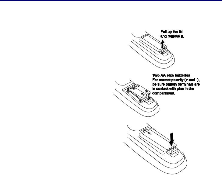
1. Introduction
Battery Installation
The Remote Control unit included with the projector does not contain batteries, though batteries are supplied as part of the complete package. To insert (or replace) the batteries, refer to the following guide.
1. Remove the battery compartment cover by squeezing the locking catch and sliding the cover in the direction of the arrow.
2. |
Insert the supplied batteries taking note |
|
of the polarity (+/-) as shown. |
3. |
Replace the cover locator, and then |
|
click locking catch into place as shown. |
13
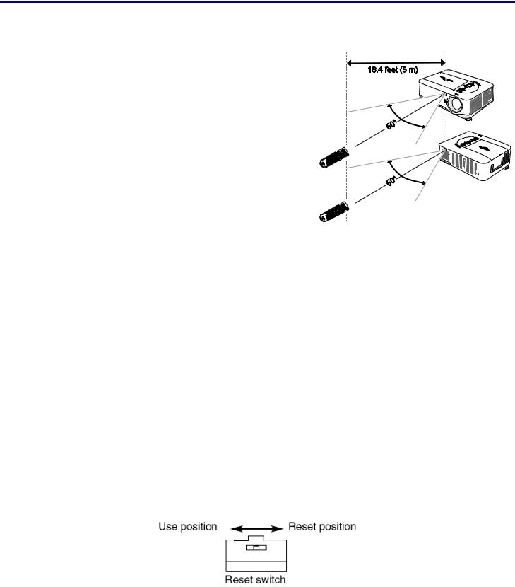
1. Introduction
Operating Range for Wireless Remote Control
Point the remote control toward the projector (to Infrared Remote Receivers) when pressing the buttons. Maximum operating range for the remote control is about 16.4 feet (5 m) and 60 degrees in front and rear of the projector.
Infrared remote receivers are provided both in front and back of the projector. You can conveniently use both of the receivers.
Remote Control Precautions
The following precautions ensure that the remote operates correctly and safely.
•Use two (2) AA or LR6 type alkaline batteries.
• Always replace batteries in sets.
•Do not use a new battery with a used one.
•Avoid contact with water or liquid.
•Do not expose the remote control to moisture or heat.
•Do not drop the remote control.
•If the battery has leaked on the remote control, carefully wipe the case clean and install new batteries.
•Risk of an explosion if battery is replaced by an incorrect type.
•Dispose of used batteries according to the instructions.
Remote Control Codes
This projector provides eight different remote control codes (Code 1–Code 8); the factory-set, initial code (Code 1) and the other seven codes (Code 2 to Code 8). This switching function prevents remote control interference when operating several projectors or video equipment at the same time.
The same code should be set on both the projector and the remote control.
For example operating the projector in “Code 7”, both the projector and the remote control must be switched to “Code 7”.
To change the code for the projector;
Select a remote control code in the Menu.
To change the code for the remote control;
Check the Reset Switch to Use position in the compartment lid on back of the remote control.
With holding down the MENU button, press the IMAGE button. By pressing the IMAGE button, the code switches in a sequential order.
To reset the code for the remote control;
Slide the Reset Switch to "Reset position" in the compartment lid on back of the remote control.
14
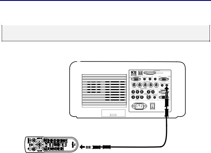
1. Introduction
Using the Remote Control in Wired Operation
Connect the supplied remote cable to the R/C jack on the projector (see Terminal Panel Features on page 9) and the other end to the remote jack on the remote control (see item 1, Part Names of the Remote Control on page 11).
Note:
Connecting the remote cable to the R/C jack on the terminal panel will make the wireless operation unavailable.
15
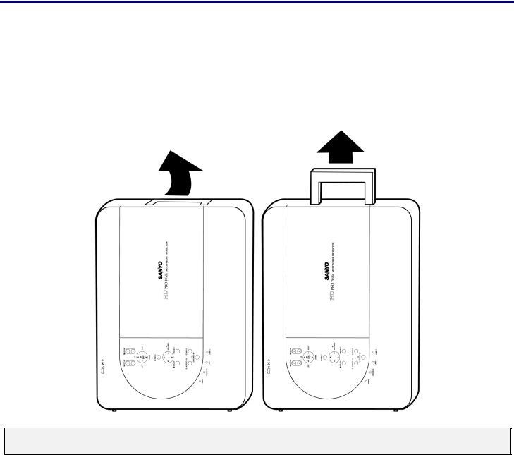
1. Introduction
Carrying the Projector
Always carry your projector by the handle.
Before moving or carrying the projector, disconnect the power cable and any other cables that may be attached to it. When moving the projector or when the projector is not in use, cover the lens with the lens cap.
To extend the projector handle, refer to the following guide.
1.Stand the projector on its end with the control panels at the bottom.
2.Lift the handle in the direction shown until it is fully extended.
Note:
Stand the projector on its end by lifting the cabinet. Do not use the handle to place the projector upright.
16
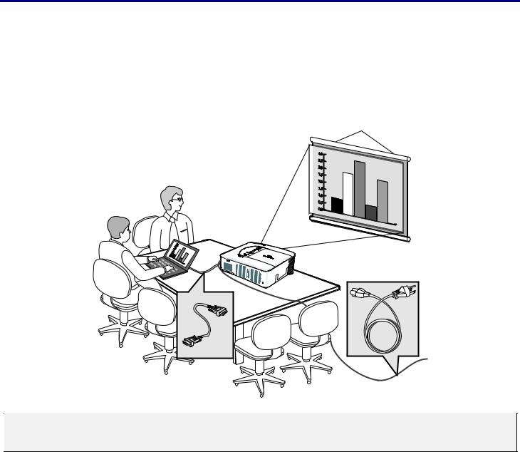
2. Installation and Connections
Setting Up the Screen and the Projector
This section briefly describes how to set up your projector and how to connect video and audio sources.
Your projector is simple to set up and use. But before you get started, you must first:
•Set up a screen and the projector.
• |
Connect your computer or video equipment to the projector. See Making Connections on page 26. |
||||||
• |
Connect the supplied power cable. See Connecting the Supplied Power Cable on page 31. |
||||||
|
|
|
|
|
|
|
|
|
|
|
|
|
|
|
|
|
|
|
|
|
|
|
|
|
|
|
|
|
|
|
|
|
|
|
|
|
|
|
|
|
|
|
|
|
|
|
|
Note:
Ensure that the power cable and any other cables are disconnected before moving the projector. When moving the projector or when it is not in use, cover the lens with the lens cap.
17
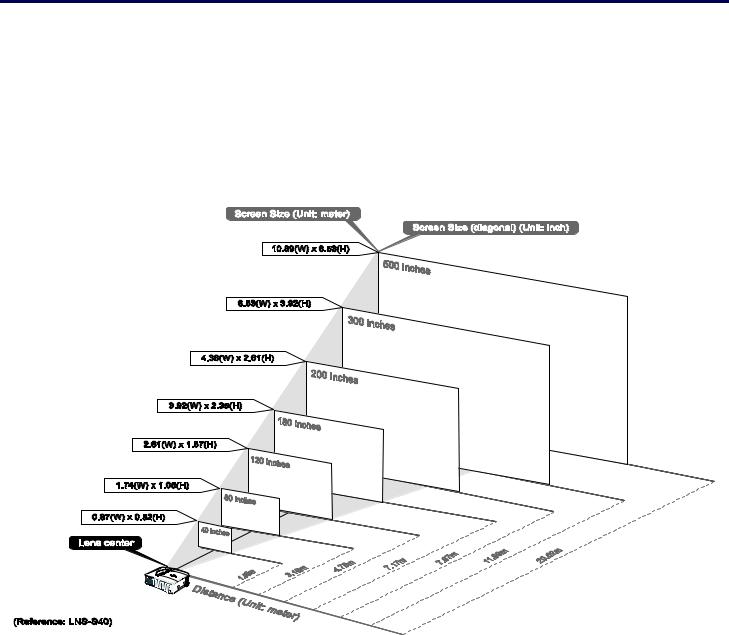
2. Installation and Connections
o Selecting a Location
Locating the projector correctly ensures optimum performance and a longer parts life. Take note of the following when setting up the projector:
•The projector table or stand should be level and sturdy.
•Position the projector so that it is perpendicular to the screen.
•Ensure cables do not cause a trip hazard.
18
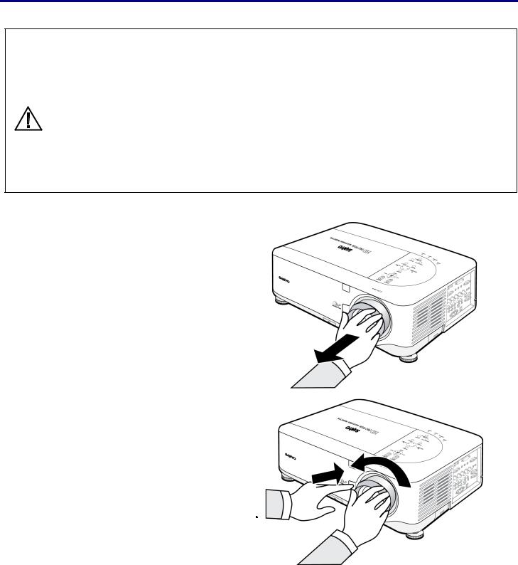
2. Installation and Connections
Installing or Removing the Optional Lens
•Do not shake or place excessive pressure on the projector or the lens components as the projector and lens components contain precision parts.
•When shipping the projector with the optional lens, remove the optional lens before shipping the projec-
tor. The lens and the lens shift mechanism may encounter damage caused by improper handling during CAUTION transportation.
• Before removing or installing the lens, be sure to turn off the projector, wait until the cooling fans stop, and turn off the main power switch.
•Do not touch the lens surface when removing or installing the lens.
•Keep fingerprints, dust or oil off the lens surface. Do not scratch the lens surface.
•Work on a level surface with a soft cloth under it to avoid scratching.
•If you remove and store the lens, attach the lens cap to the projector to keep off dust and dirt.
Removing the Existing Lens From the Projector
1. Pull out the lens cap.
2. |
Push the LENS RELEASE button all the way |
in and rotate the lens counterclockwise. |
|
|
The existing lens will be disengaged. |
|
|
|
Note: |
|
If the lens cannot be removed even by |
|
using the LENS RELEASE button, the |
|
anti-theft screw for lens may be in use |
|
to secure the lens. If that is the case, |
|
remove the anti-theft screw first. |
19
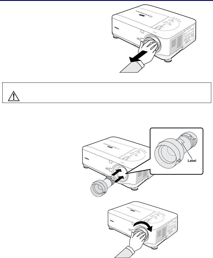
2. Installation and Connections
3. |
Pull out the existing lens slowly. |
CAUTION When Installing the lens into the projector, be sure to remove the lens cap from the back of the optional lens before installing the optional lens into the projector. Failure to do so will cause damage to the projector.
Installing the New Lens
1. Insert the lens label side up.
2. Rotate the lens clockwise until it clicks into place.
20
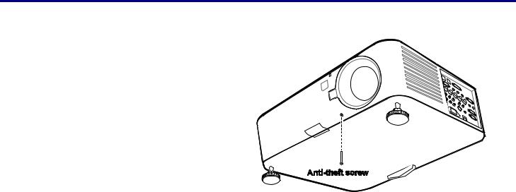
2. Installation and Connections
Installing the New Lens Using the anti-theft screw
Using the anti-theft screw to prevent theft of the lens.
Tighten the supplied anti-theft screw on the front bottom.
21
Loading...