


UN65NU6900F
Table of contents
 Loading...
UHD TV
Project : UNU6900P
Chassis : UEZ83
Model : UN65NU6900F
UN75NU6900F
SERVICE
UHD TV Contents
1. Precautions
2. Product specications
3. Disassembly and Reassembly
4. Troubleshooting
5. Wiring Diagram
UN65NU6900F
Manual
UN75NU6900F

Contents
1. Precautions ....................................................................................................................... 1-1
1-1. Safety Precautions .......................................................................................................................1-1
1-1-1. Warnings .............................................................................................................................1-1
1-1-2. Servicing the LED TV ........................................................................................................1-1
1-1-3. Fire and Shock Hazard ......................................................................................................1-1
1-1-4. Product Safety Notices.................................................................................................... 1-2
1-2. Servicing Precautions ................................................................................................................. 1-3
1-2-1. General Servicing Precautions ...................................................................................... 1-3
1-3. Static Electricity Precautions .................................................................................................... 1-4
1-4. Installation Precautions ............................................................................................................. 1-5
2. Product Specications .................................................................................................... 2-1
2-1. Product information .....................................................................................................................2-1
2-2. Product specication .................................................................................................................. 2-3
2-3. Accessories ...................................................................................................................................2-9
2-4. Viewing the Functions ..............................................................................................................2-10
2-5. The Remote Control .................................................................................................................. 2-14
3. Disassembly and Reassemble ........................................................................................ 3-1
3-1. Disassembly ................................................................................................................................. 3-1
4. Troubleshooting ..............................................................................................................4-1
4-1. Power ............................................................................................................................................. 4-1
4-1-1. Function Control Operation Test ................................................................................... 4-1
4-1-2. TV POWER STANDBY TEST .............................................................................................4-2
4-1-3. TV POWER ON SEQUENCE TEST ...................................................................................4-4
4-1-4. SMPS/PANEL BACKLIGHT TEST (Parallel Wired SMPS Panel Connections) .........4-6
4-2. Video .............................................................................................................................................4-8
4-2-1. Customer Picture Test .....................................................................................................4-8
4-2-2. Check Test Patterns ........................................................................................................4-9
4-2-3. MAIN/T-CON BOARD ....................................................................................................4-10
4-3. Audio ........................................................................................................................................... 4-13
4-4. Network ......................................................................................................................................4-14
4-5. Smart Hub .................................................................................................................................. 4-15
4-6. Factory Mode ............................................................................................................................. 4-17
4-7. Factory Mode Adjustments ......................................................................................................4-23
4-7-1. Entering Factory Mode ..................................................................................................4-23
4-7-2. Detail Factory Option ....................................................................................................4-24
4-7-3. Factory Data ...................................................................................................................4-26
4-8. Replacing Main Board ..............................................................................................................4-39
4-9. White Balance ............................................................................................................................4-41
4-9-1. Calibration ......................................................................................................................4-41
4-9-2. Service Adjustment ......................................................................................................4-41
4-9-3. Adjustment ....................................................................................................................4-43

4-10. LED Indicator Test .................................................................................................................. 4-44
4-10-1. Diagnostic Methods - Flashing Symptom Codes .................................................. 4-44
4-11. Updating the TV’s Software ...................................................................................................4-45
4-11-1. By USB ............................................................................................................................4-45
4-11-2. By Online .......................................................................................................................4-45
4-11-3. Stanby mode upgrade(O/On) ..................................................................................4-45
5. Wiring Diagram ................................................................................................................ 5-1
5-1. Wiring Diagram .............................................................................................................................5-1
5-1-1. Cables .................................................................................................................................5-3
5-2. Connector .....................................................................................................................................5-4
5-2-1. Main Board........................................................................................................................5-4
5-2-2. SMPS Board ......................................................................................................................5-8

This Service Manual is a property of Samsung Electronics Co.,Ltd.
Any unauthorized use of Manual can be punished under applicable
International and/or domestic law.
© 2018 Samsung Electronics Co.,Ltd.
All rights reserved.
Printed in Korea
1. Precautions
1. Precautions
1-1. Safety Precautions
Follow these safety, servicing and ESD precautions to prevent damage and to protect against potential hazards such as
electrical shock.
1-1-1. Warnings
For continued safety, do not attempt to modify the circuit board.
WARNING
1-1-2. Servicing the LED TV
When servicing the LED TV, Disconnect the AC line cord from the AC outlet.1.
It is essential that service technicians have an accurate voltage meter available at all times. Check the calibration of 2.
this meter periodically.
1-1-3. Fire and Shock Hazard
Before returning the monitor to the user, perform the following safety checks:
Inspect each lead dress to make certain that the leads are not pinched or that hardware is not lodged between the 1.
chassis and other metal parts in the monitor.
Inspect all protective devices such as nonmetallic control knobs, insulating materials, cabinet backs, adjustment and 2.
compartment covers or shields, isolation resistorcapacitor networks, mechanical insulators, etc.
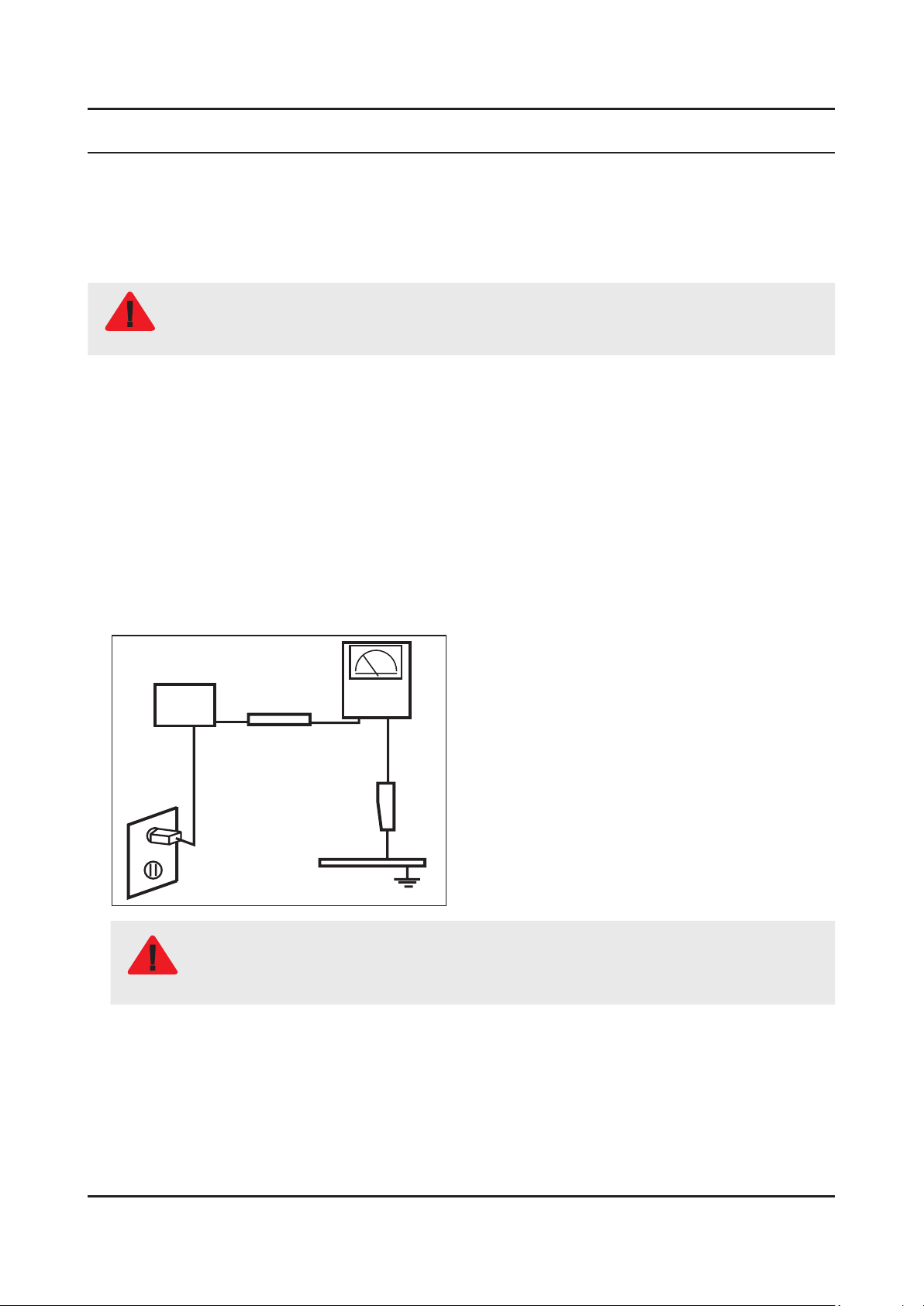
Leakage Current Hot Check:3.
Disconnect the AC power and DC power jack before servicing.
(READING SHOULD)
DEVICE
UNDER
TEST
ALSO TEST WITH PLUG
REVERSED (USING AC
ADAPTER PLUG AS
REQUIRED)
NOT BE ABOVE 0.5mA
2-WIRE CORD
TEST ALL EXPOSED
METAL SURFACES
LEAKAGE
CURRENT
TESTER
EARTH
GROUND
Do not use an isolation transformer during this test.
Use a leakage current tester or a metering system that complies with American National Standards
WARNING
Institute (ANSI C101.1, Leakage Current for Appliances), and Underwriters Laboratories (UL
Publication UL1410, 59.7).
With the unit completely reassembled, plug the AC line cord directly into a 120V AC outlet. With the unit’s AC switch 4.
rst in the ON position and then OFF, measure the current between a known earth ground (metal water pipe, conduit,
etc.) and all exposed metal parts, including: metal cabinets, screwheads and control shafts.
The current measured should not exceed 0.5 milliamp.
Reverse the power-plug prongs in the AC outlet and repeat the test.
1-1

1-2
1. Precautions
1-1-4. Product Safety Notices
Some electrical and mechanical parts have special safetyrelated characteristics which are often not evident from
visual inspection. The protection they give may not be obtained by replacing them with components rated for higher
voltage, wattage, etc. Parts that have special safety characteristics are identied by on schematics and parts lists.
A substitute replacement that does not have the same safety characteristics as the recommended replacement part
might create shock, re and/or other hazards. Product safety is under review continuously and new instructions are
issued whenever appropriate.

1-3
1. Precautions
1-2. Servicing Precautions
An electrolytic capacitor installed with the wrong polarity might explode.
WARNING
Before servicing units covered by this service manual, read and follow the Safety Precautions section of
CAUTION
NOTE
1-2-1. General Servicing Precautions
Always unplug the unit’s AC power cord from the AC power source and disconnect the DC Power Jack before attempting 1.
to: (a) remove or reinstall any component or assembly, (b) disconnect PCB plugs or connectors, (c) connect a test
component in parallel with an electrolytic capacitor.
Some components are raised above the printed circuit board for safety. An insulation tube or tape is sometimes used. 2.
The internal wiring is sometimes clamped to prevent contact with thermally hot components. Reinstall all such
elements to their original position.
After servicing, always check that the screws, components and wiring have been correctly reinstalled. Make sure that 3.
the area around the serviced part has not been damaged.
Check the insulation between the blades of the AC plug and accessible conductive parts (examples: metal panels, input 4.
terminals and earphone jacks).
Insulation Checking Procedure: Disconnect the power cord from the AC source and turn the power switch ON. Connect 5.
an insulation resistance meter (500 V) to theblades of the AC plug. The insulation resistance between each blade of the
AC plug and accessible conductive parts (see above) should be greater than 1 megohm.
Always connect a test instrument’s ground lead to the instrument chassis ground before connecting the positive lead; 6.
always remove the instrument’s ground lead last.
this manual.
If unforeseen circumstances create conict between the following servicing precautions and any of the
safety precautions, always follow the safety precautions.
1-4
1. Precautions
1-3. Static Electricity Precautions
Some semiconductor (solid state) devices can be easily damaged by static electricity. Such components are commonly
called Electrostatically Sensitive Devices (ESD). Examples of typical ESD are integrated circuits and some eld-eect
transistors. The following techniques will reduce the incidence of component damage caused by static electricity.
Immediately before handling any semiconductor components or assemblies, drain the electrostatic charge from your 1.
body by touching a known earth ground. Alternatively, wear a discharging wrist-strap device. To avoid a shock hazard,
be sure to remove the wrist strap before applying power to the monitor.
After removing an ESD-equipped assembly, place it on a conductive surface such as aluminum foil to prevent 2.
accumulation of an electrostatic charge.
Do not use freon-propelled chemicals. These can generate electrical charges sufcient to damage ESDs.3.
Use only a grounded-tip soldering iron to solder or desolder ESDs.4.
Use only an anti-static solder removal device. Some solder removal devices not classied as “anti-static” can generate 5.
electrical charges sufcient to damage ESDs.
Do not remove a replacement ESD from its protective package until you are ready to install it. Most replacement ESDs 6.
are packaged with leads that are electrically shorted together by conductive foam, aluminum foil or other conductive
materials.
Immediately before removing the protective material from the leads of a replacement ESD, touch the protective 7.
material to the chassis or circuit assembly into which the device will be installed.
Be sure no power is applied to the chassis or circuit and observe all other safety precautions.
CAUTION
Minimize body motions when handling unpackaged replacement ESDs. Motions such as brushing clothes together, or 8.
lifting your foot from a carpeted oor can generate enough static electricity to damage an ESD.
1-5
1. Precautions
1-4. Installation Precautions
For safety reasons, more than a people are required for carrying the product.1.
Keep the power cord away from any heat emitting devices, as a melted covering may cause re or electric shock.2.
Do not place the product in areas with poor ventilation such as a bookshelf or closet. The increased internal 3.
temperature may cause re.
Bend the external antenna cable when connecting it to the product. This is a measure to protect it from being exposed 4.
to moisture. Otherwise, it may cause a re or electric shock.
Make sure to turn the power o and unplug the power cord from the outlet before repositioning the product. Also check 5.
the antenna cable or the external connectors if they are fully unplugged. Damage to the cord may cause re or electric
shock.
Keep the antenna far away from any high-voltage cables and install it rmly. Contact with the highvoltage cable or the 6.
antenna falling over may cause re or electric shock.
When installing the product, leave enough space (0.4m) between the product and the wall for ventilation purposes. 7.
A rise in temperature within the product may cause re.
If an equipment is provided with a replaceable battery, and if replacement by an incorrect type could result in an 8.
explosion (for example, with some lithium batteries), the following applies:
Risk of explosion if battery is replaced by an incorrect type dispose of used batteries according •
to the instructions.
Do not dispose of batteries in a re.•
Do not short circuit, disassemble or overheat the batteries.•
CAUTION
Danger of explosion if battery is incorrectly replaced. Replace only with the same or equivalent •
type.
Do not be exposed to excessive heat such as sunshine, re or the like.•
2. Product Specications
2-1. Product information
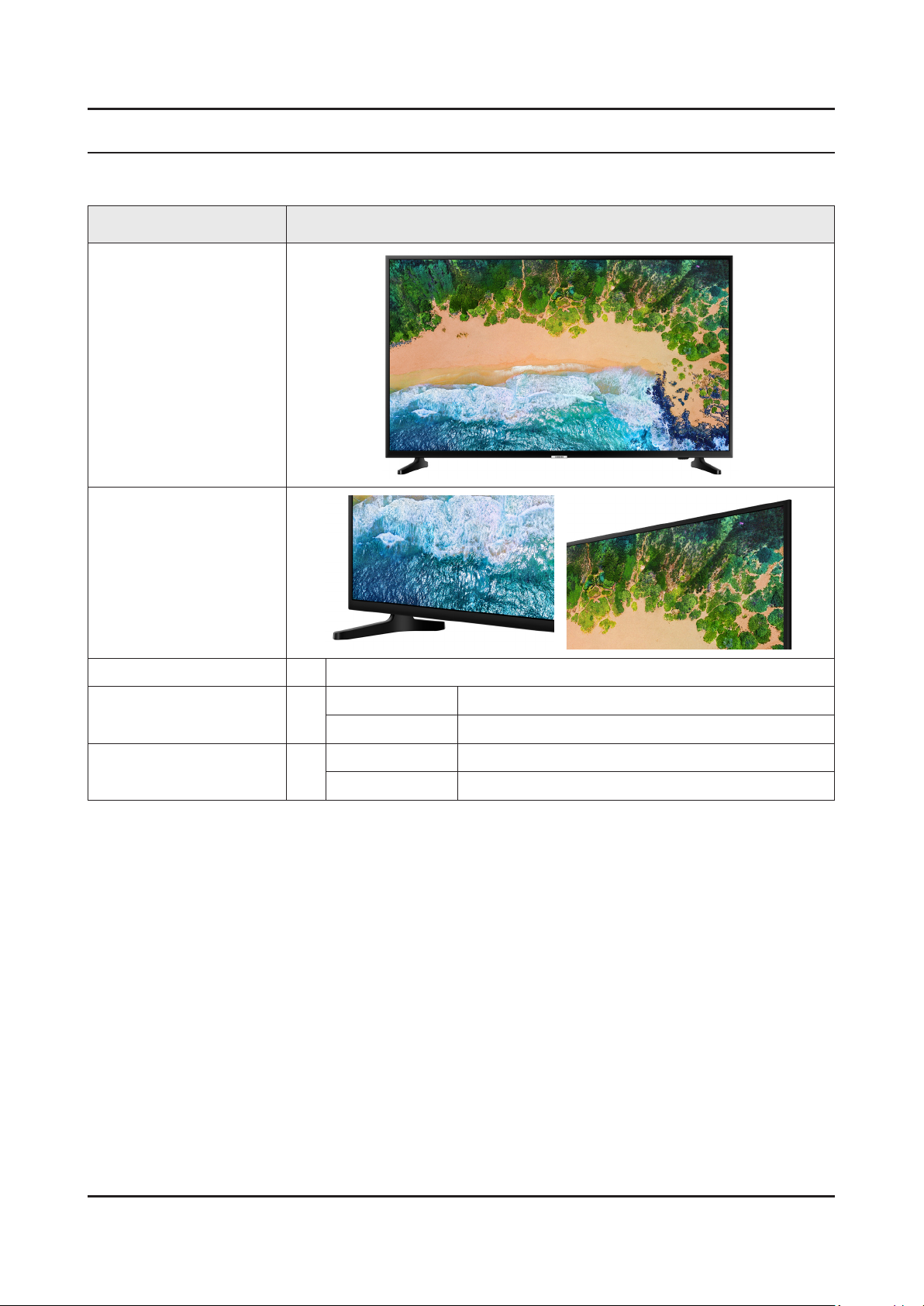
Model UN65NU6900F
Front View
2. Product specications
Detail View
Color 65" Front : GLOSSY BLACK / Stand : SHADOW BLACK
Dimensions
(W x H x D)
Weight 65"
65"
Body 57.4 x 33.0 x 2.4 inches (1457.5 x 837.3 x 59.7 mm)
With Stand 57.4 x 34.9 x 12.5 inches (1457.5 x 887.4 x 317.3 mm)
Without Stand 55.1 lbs (25.0 kg)
With Stand 55.8 lbs (25.3 kg)
2-1
2-2
2. Product specications
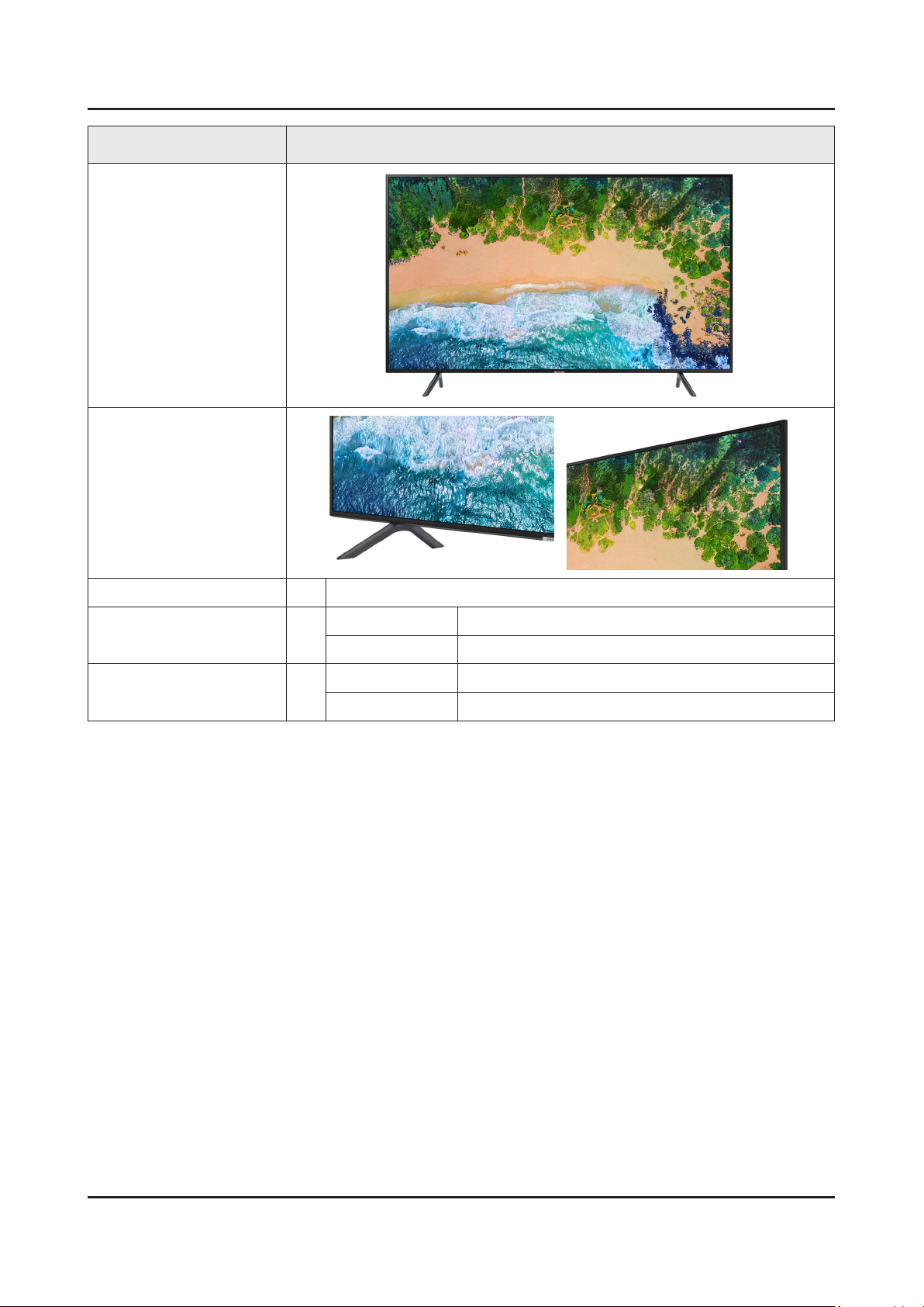
Model UN75NU6900F
Front View
Detail View
Color 75" Front : GLOSSY BLACK / Stand : DARK GRAY
Dimensions
(W x H x D)
Weight 75"
75"
Body 66.3 x 38.0 x 2.4 inches (1684.6 x 966.4 x 60.6 mm)
With Stand
Without Stand 81.6 lbs (37.0 kg)
With Stand 82.7 lbs (37.5 kg)
66.3 x 41.6 x 14.0 inches (1684.6 x 1056.5 x 356.1 mm)
2-3
2. Product specications
2-2. Product specication
NOTE
Design and specications are subject to change without prior notice.
Item UN65NU6900FXZA
General Information
Display
Video
Product LED
Cabinet Basic Code 65NP1
Series 7
Country UNITED STATES
Platform(TV) Novatek | Kant-SU
Screen Size 65"
Resolution 3,840 x 2,160
Ultra Black N /A
Screen Curvature N/A
10 bit Support N/A
Picture Engine UHD Engine
Motion Rate 120
HDR (High Dynamic Range) HDR
HDR 10+ Yes
HLG (Hybrid Log Gamma) Yes
Contrast Mega Contrast
Color Pur Color
Viewing Angle N/A
Audio
Smart Service
Micro Dimming N/A
Auto Depth Enhancer N/A
Contrast Enhancer Yes
Auto Motion Plus Yes
Film Mode Yes
Natural Mode Support Yes
Dolby Digital Plus Yes
DTS Codec N/A
Sound Output (RMS) 20W
Speaker Type 2CH
Woofer N/A
Multiroom Link Yes
Blutooth Audio N /A
Voice Interaction N/A
Samsung SMART TV Smart
Bixby N/A
2-4
2. Product specications
Item UN65NU6900FXZA
Smart Service
Convergence
Tuner/Broadcasting
Connectivity
TV Plus Yes(US Only)
Web Browser Yes
SmartThings App Support Yes
SmartThings N/A
Universal Guide Yes
TV to Mobile - Mirroring N/A
Mobile to TV - Mirroring, DLNA Yes
360 Video Player N /A
360 Camera Support N/A
Easy Setup N /A
Bluetooth Low Energy N /A
WiFi Direct Yes
TV Sound to Mobile N/A
Sound Mirroring N/A
Digital Broadcasting ATSC/ClearQAM
Analog Tuner Yes
HDMI 2
USB 1
Design
Additional Feature
Component In (Y/Pb/Pr) N/A
Composite In (AV) N/A
Ethernet (LAN) Yes
Audio Out (Mini Jack) N/A
Digital Audio Out (Optical) 1
RF In (Terrestrial / Cable input / Satellite input) 1/1(Common Use for Terrestrial)/0
Ex-Link ( RS-232C ) N/A
CI Slot N/A
HDMI A / Return Ch. Support Yes
HDMI Quick Switch Yes
Wireless LAN Built-in Yes
Anynet+ (HDMI-CEC) Yes
Design Slim
Bezel Type VNB
Front Color Glossy Black
Light Eect (Deco) N /A
Stand Type Simple Stand (Matt)
Swivel (Left/Right) N/A
Art Mode (The Frame) N/A
Motion Detection (The Frame) N/A
2-5
2. Product specications
Item UN65NU6900FXZA
Additional Feature
Ambient Mode N /A
Instant On Yes
Processor Quad-Core
Accessibility
Digital Clean View Yes
Auto Channel Search Yes
Auto Power O Yes
Caption (Subtitle) Yes
Connect Share™ (HDD) Yes
ConnectShare™ (USB 2.0) Yes
EPG Yes
Game Mode Yes (Basic)
OSD Language English, Spanish, French
BT HID Built-in N /A
USB HID Support Yes
Teletext (TTX) N/A
V-Chip Yes
Voice Guide(US English)/ Enlarge/ High
Contrast/ Learn TV Remote(US English)
Eco Feature
Power
IPv6 Support Yes
MBR Support N/A
Ultra Clean View N /A
Energy Star Yes
Eco Sensor Yes
Power Supply AC110-120V 50/60Hz
Power Consumption (Max) 180 W
Power Consumption (Stand-by) 0.3 W
Power Consumption (Typical) 75 W
2-6
2. Product specications
Item UN75NU6900FXZA
General Information
Display
Video
Product LED
Cabinet Basic Code U75NP1
Series 7
Country UNITED STATES
Platform(TV) Novatek | Kant-SU
Screen Size 75"
Resolution 3,840 x 2,160
Ultra Black N /A
Screen Curvature N/A
10 bit Support N/A
Picture Engine UHD Engine
Motion Rate 120
HDR (High Dynamic Range) HDR
HDR 10+ Yes
HLG (Hybrid Log Gamma) Yes
Contrast Mega Contrast
Viewing Angle N/A
Color Pur Color
Audio
Smart Service
Micro Dimming N/A
Local Dimming N /A
Auto Depth Enhancer N/A
Contrast Enhancer Yes
Auto Motion Plus Yes
Film Mode Yes
Natural Mode Support Yes
Dolby Digital Plus Yes
DTS Codec N/A
Sound Output (RMS) 20W
Speaker Type 2CH
Woofer N/A
Multiroom Link Yes
Blutooth Audio N /A
Voice Interaction N/A
Samsung SMART TV Smart
Bixby N/A
TV Plus Yes(US Only)
Web Browser Yes

2-7
2. Product specications
Item UN75NU6900FXZA
Smart Service
Convergence
Tuner/Broadcasting
Connectivity
SmartThings App Support Yes
SmartThings N/A
Universal Guide Yes
TV to Mobile - Mirroring N/A
Mobile to TV - Mirroring, DLNA Yes
360 Video Player N /A
360 Camera Support N/A
Easy Setup N /A
Bluetooth Low Energy N /A
WiFi Direct Yes
TV Sound to Mobile N/A
Sound Mirroring N/A
Digital Broadcasting ATSC/ClearQAM
Analog Tuner Yes
HDMI 2
USB 1
Component In (Y/Pb/Pr) N/A
Composite In (AV) N/A
Design
Additional Feature
Ethernet (LAN) Yes
Audio Out (Mini Jack) N/A
Digital Audio Out (Optical) 1
RF In (Terrestrial / Cable input / Satellite input) 1/1(Common Use for Terrestrial)/0
Ex-Link ( RS-232C ) N/A
CI Slot N/A
HDMI A / Return Ch. Support Yes
HDMI Quick Switch Yes
Wireless LAN Built-in Yes
Anynet+ (HDMI-CEC) Yes
Design New Edge (Skinny Bezel)
Bezel Type VNB
Front Color Charcoal Black
Light Eect (Deco) N /A
Stand Type Simple Luminus
Swivel (Left/Right) N/A
Art Mode (The Frame) N/A
Motion Detection (The Frame) N/A
Ambient Mode N /A
Instant On Yes
2-8
2. Product specications
Item UN75NU6900FXZA
Additional Feature
Processor Quad-Core
Accessibility
Digital Clean View Yes
Auto Channel Search Yes
Auto Power O Yes
Caption (Subtitle) Yes
Connect Share™ (HDD) Yes
ConnectShare™ (USB 2.0) Yes
EPG Yes
Game Mode Yes
OSD Language English, Spanish, French
BT HID Built-in N /A
USB HID Support Yes
Teletext (TTX) N/A
V-Chip Yes
IPv6 Support Yes
MBR Support N/A
Voice Guide(US English)/ Enlarge/ High
Contrast/ Learn TV Remote(US English)
Eco Feature
Power
Ultra Clean View N /A
Energy Star Yes
Eco Sensor Yes
Power Supply AC110-120V 50/60Hz
Power Consumption (Max) 220 W
Power Consumption (Stand-by) 0.3 W
Power Consumption (Typical) 105 W

2-9
2. Product specications
2-3. Accessories
NOTE
The items’ colors and shapes may vary depending on the model.•
Cables not included in the package contents can be purchased separately.•
The part code for some accessories may dier depending on your region.•
The provided accessories may vary depending on the model.•
Product Code. No Product Code. No
3903-001117 (65")
Remote Control• BN59-01301A Power Cord•
3903-001132 (75")
BN68-09212A (65")
Batteries (AAA x 2)• 4301-000103 User Manual•
BN68-09212F (75")
Regulatory Guide• BN68-08114Q Holder P-Ring• BN96-43169A
2-10
2. Product specications
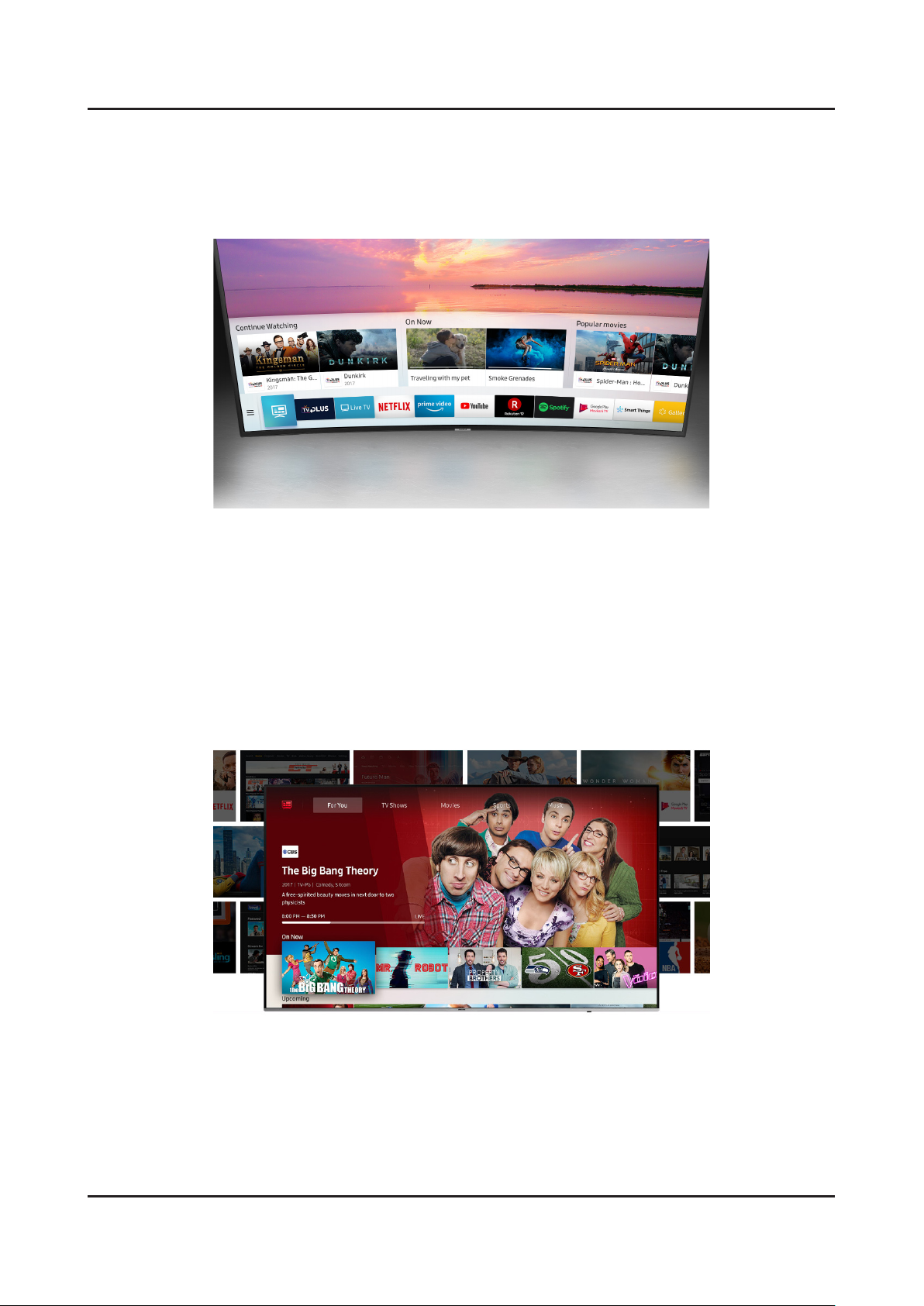
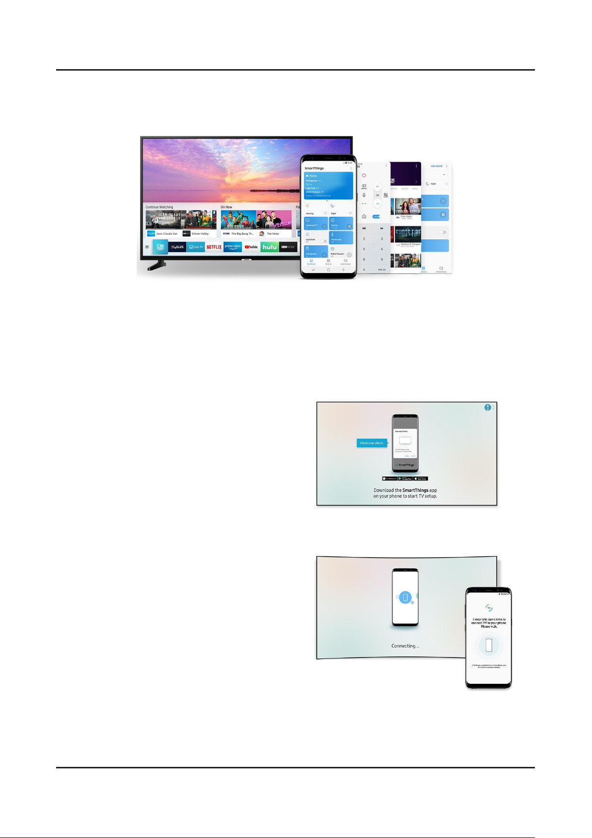
2-4. Viewing the Functions
An intelligent way to enjoy the smart TV
Get to your entertainment the faster, easier, and intelligent way. One Depth gathers a variety of content for you on one
screen. Get easy access to dierent content providers and check out the thumbnail previews before diving in.
Images are simulated and for illustration purposes only. The appearance and design specications which is not •
aecting to product performance are subject to change without notice.
Smart service and GUI(Graphic User Interface) may vary by model and region.•
All devices must be on the same network and Internet connection is required. •
Netix streaming membership required.•
Universal Guide
Don't waste time worrying about what to watch next. Universal Guide not only shows you popular shows and content,
it recommends content specically to your viewing preference by analyzing your viewing pattern over the past few
months.
Agreement of the Smart Hub Terms and Conditions and Privacy Policy is required before use. •
Smart service and GUI(Graphic User Interface) may vary by model and region.•
2-11
2. Product specications
SmartThings App, just one app for all
The SmartThings app oers features such as Remote Control and Mirror Screen.
SmartThings compatible devices may vary by region. •
This function may dier by mobile and OS(Operation System). •
Download and installation of SmartThings app are reuired.•
Mobile Set-up
Step 1
Download SmartThings App to set up Smart TV.
Step 2
If your mobile is connected to Wi-Fi, the network
information will be shared with your TV.
2-12
2. Product specications
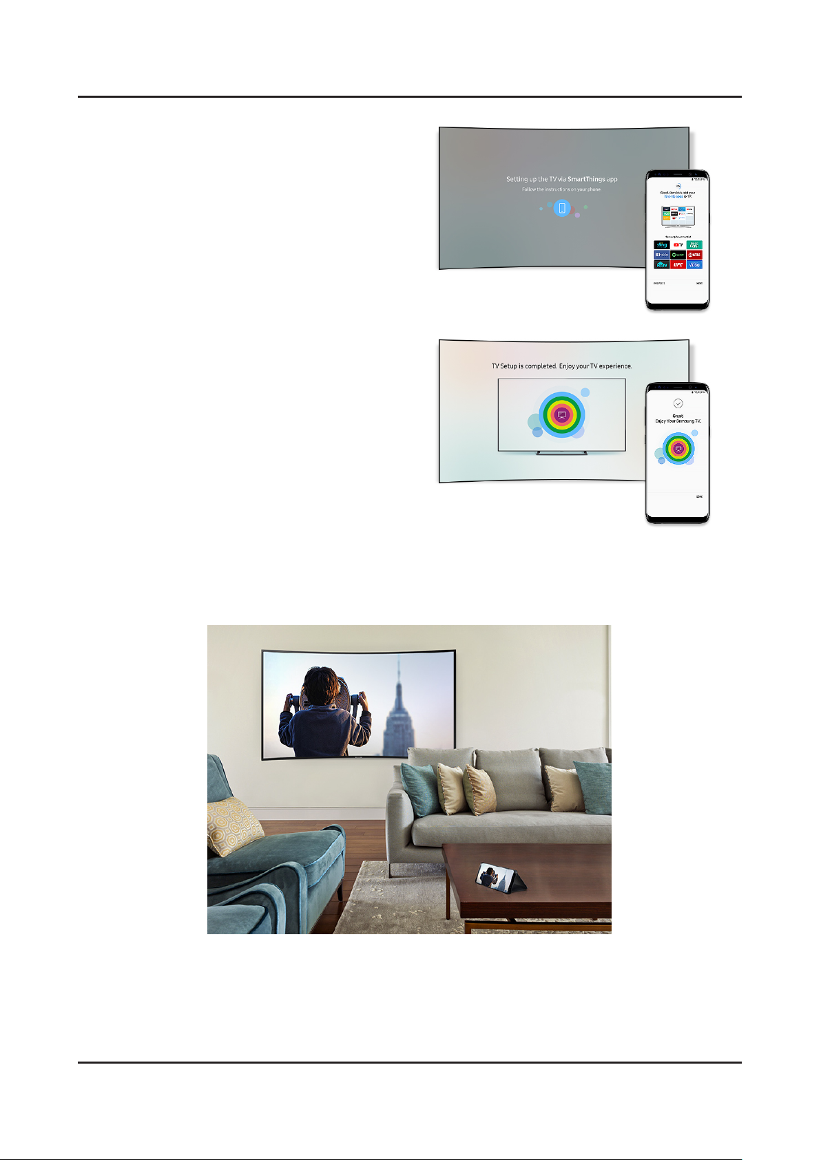
Step 3
If your mobile is linked to a Samsung Account, the
account information will automatically be shared with
your TV.
Setup process requires a Samsung Account. TV must •
have an internet connection for mobile set-up.
Step 4
Select the apps you want to enjoy and add them to the
Smart Hub. That's it! Now, just kick back and enjoy your
Smart TV!
The set-up process can also be done by remote •
control.
Cntent Sync & Share
Take full advantage of the Samsung Cloud. Seamlessly connect your Samsung smart devices to sync photos. Now you
can share your mobile pictures and enjoy it on the TV or refrigerator screen.
Compatible devieces only.•
2-13
2. Product specications
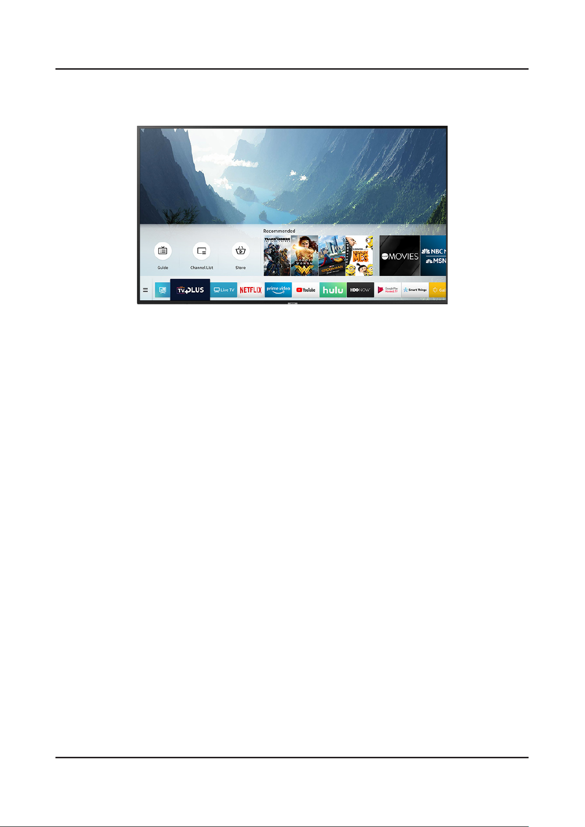
TV Plus
Get access to a wide range of 4K UHD and HDR content. TV Plus oers latest content and movies in amazing resolution
so you enjoy a cinematic experience at the comfort of your own home.
TV Plus service and GUI may vary by region.•
2. Product specications
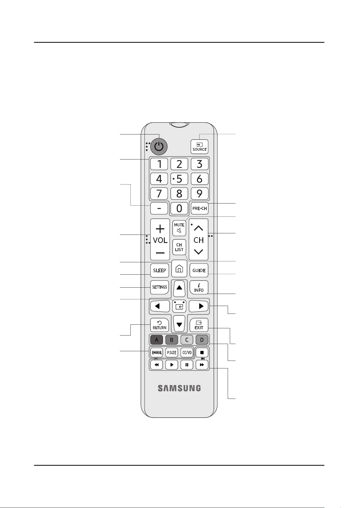
02 The Remote Control
About the Buttons on the Remote Control
࡙ The images, buttons, and functions of the remote control may differ depending on the model.
࡙ The remote control has Braille points on the Power, Channel, Volume, and Select buttons and can be used by
visually impaired persons.
Displays and selects the available
video sources.
Turns the sound on and off.
Launches the Channel List.
Changes channels.
Exits the menu.
Use these buttons according to the
directions on the TV screen.
Use these buttons with a specific
feature, according to the directions
on the TV's screen.
Displays the Electronic Program
Guide (EPG).
Displays information on the TV
screen.
Moves the cursor, selects the
onscreen menu items, and changes
the values seen on the TV's menu.
Turns the TV on and off.
Gives direct access to channels.
Adjusts the volume.
Selects additional digital channels
being broadcast by the same digital
station. For example, to select
channel ‘54-3’, press ‘54’, then press
‘-’ and ‘3’.
Returns to the previous channel.
Automatically shuts off the TV at a
preset time.
Displays the main on-screen menu.
Returns to the previous menu.
E-MANUAL
Displays the e-Manual.
P.SIZE
Changes the picture size.
CC/VD
When pressed the button, the
Accessibility Shortcuts menu
appears.
E (Select)
Press this button to select or run a
focused item.
Returns to the Home Screen.
2-5. The Remote Control
About the Buttons on the Remote Control
This remote control has Braille points on the Power, Channel, Volume, and Enter buttons and can be used by visually impaired persons.
The images, buttons, and functions of the remote control may dier depending on the model. -
2-14
3. Disassembly and Reassemble
3. Disassembly and Reassemble
This section of the service manual describes the disassembly and reassembly procedures for the LED TV.
Disconnect the LED TV from the power source before disassembly.1.
Follow these directions carefully.2.
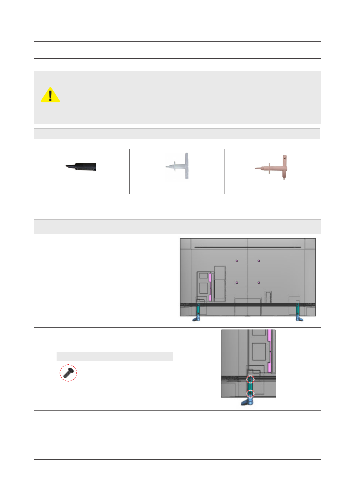
Use the Samsung Open Jig and Cushion to remove the Rear Cover. -
CAUTION
Open Jigs
Please Use Lower Open Jig, for opening of Screwless rear cover.
BN81-12844A BN81-14946A BN81-14946B
Open Jig Tool, Protection Cushion (curved models Only)•
Recommended Torque for Cabinet/Stand screws : 22.0 ~ 26.5lbf -
A strength of Torque can be changed depending on the situation.•
3-1. Disassembly
Description & Screws Picture Description
Carefully position the TV so that the screen is
1
facing downwards.
Make sure to place the TV upon a soft •
cushion or any material that will prevent
damage to the screen.
Remove the screws connecting the stand to the
2
TV. Then carefully remove the stand.
Screws
6003-001334 x 4
SCREW-TAPTYPE : M4 x L14, ZPC(BLK)
SET + STAND
•
3-1
3-2
3. Disassembly and Reassemble
Description & Screws Picture Description
3-1
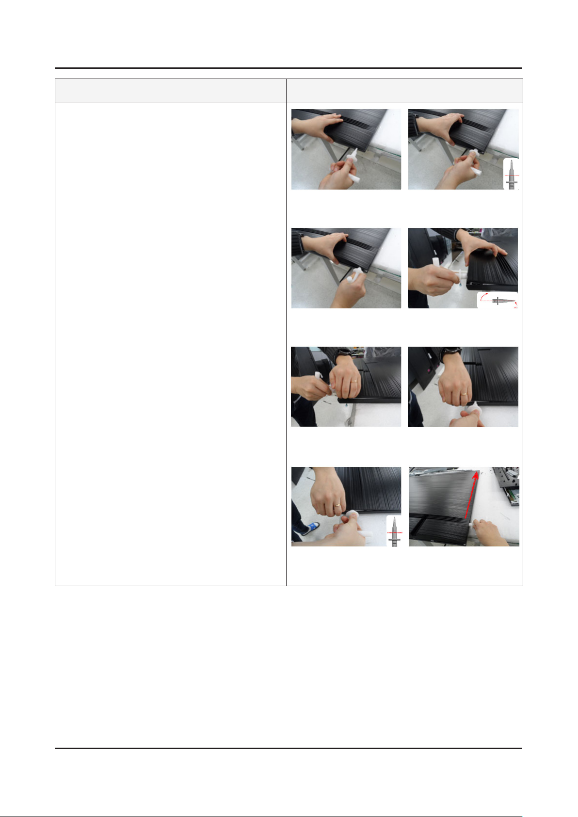
Removing the 'ASSY REAR COVER'.
(Please follow 8 sequence on right.)
Ready to insert open jig 1.
adjust jig edge to hole.
3.
Rotate open jig to 90-degree.
Insert open jig till red line.2.
Lift jig to unlock wire hook 4.
on bottom.
6.
Insert hand and retain gap.5.
Insert open jig till red line.7.
Take out jig and insert in
side gap.
8.
Disassemble Hooks of
Cover Rear along the side.
3-3
3. Disassembly and Reassemble
Description & Screws Picture Description
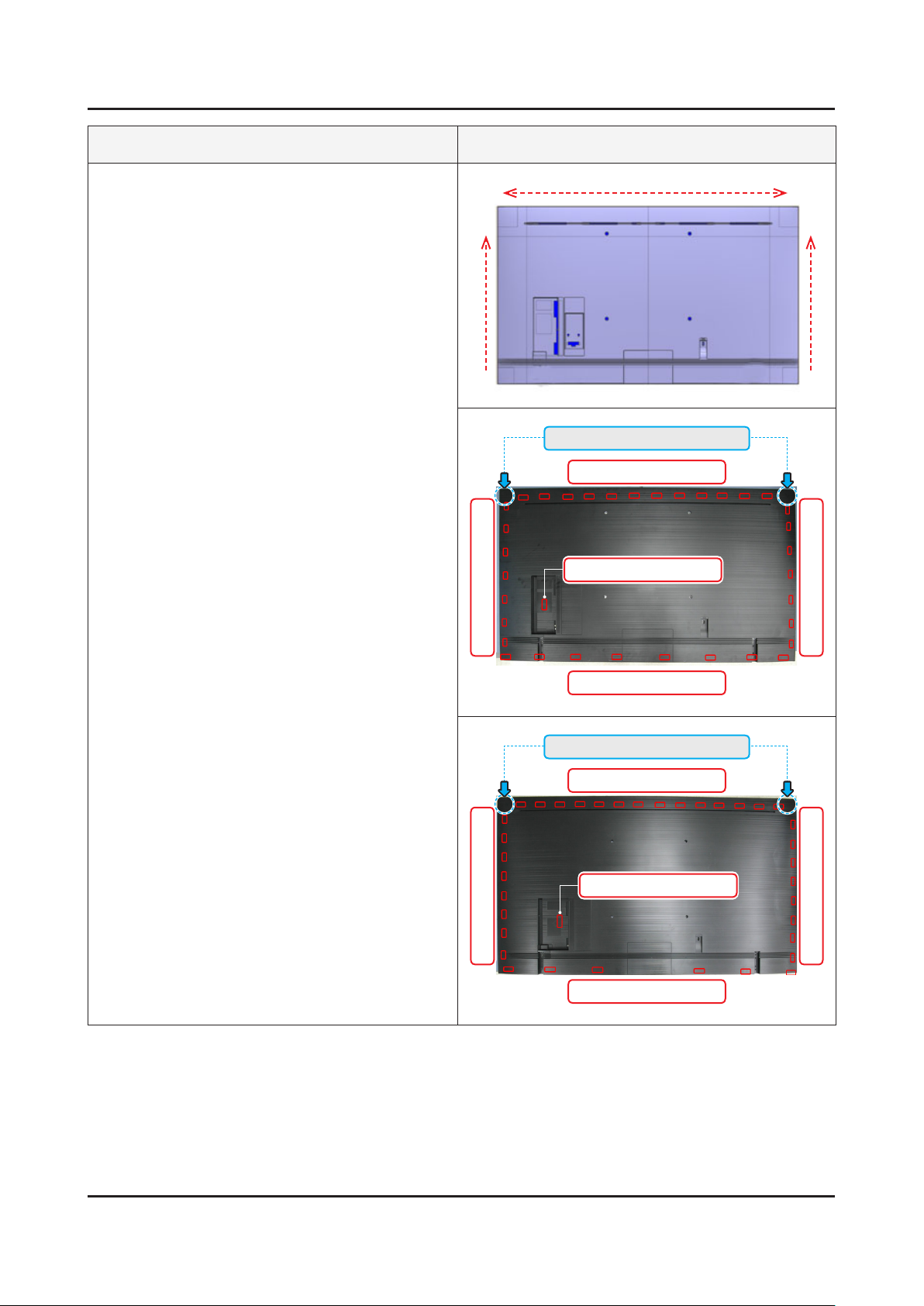
3-2
Disassemble all Hooks of Cover Rear along the
three side.
Locking tabs locations
65"•
Jig Direction
L : 7 point Locking
Jig Direction
Jig Direction
Top Corner : 2 point (Snap Hook)
Top : 12 point Locking
Side AV : 1 Point Locking
R : 7 point Locking
Bottom : 8 point Locking
75"•
Top Corner : 2 point (Snap Hook)
Top : 14 point Locking
Side AV : 1 Point Locking
L : 8 point Locking
Bottom : 6 point Locking
R : 8 point Locking
3-4
3. Disassembly and Reassemble
Description & Screws Picture Description
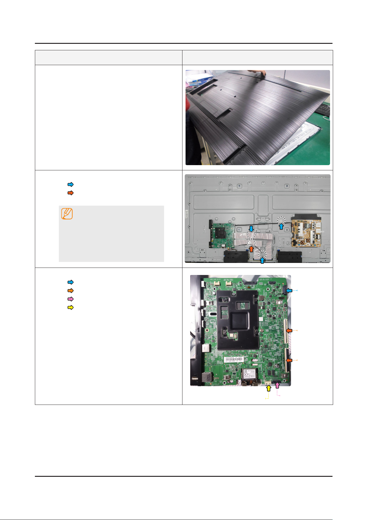
3-3
4
Lift top side then pull back to remove the back
cover.
Remove the Electric tapes shown on the images.
• EMI Filament Tape (Dressing)
• Filament Tape (Dressing)
NOTE
When assembling the TV, the •
electric tapes must be applied
on the same locations. Please
remember to take a picture of where
thetapeswererstapplied.
Remove the Cables.
5
• Power Wire
• FFC Cables
• IR Wrie
• SPK Wire
SPK Wire
Power Wire
FFC Cables
FFC Cables
IR Wrie
3-5
3. Disassembly and Reassemble
Description & Screws Picture Description
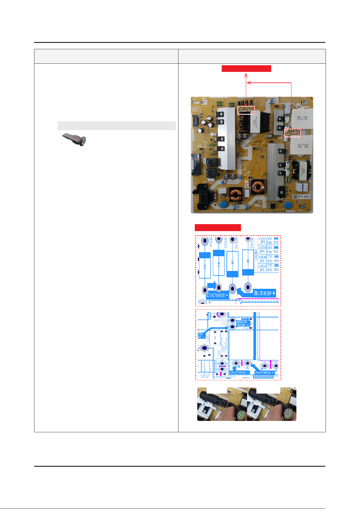
6-1
Discharge Capacitors.
65"•
Before remove SMPS, Must discharge •
capacitors for your safety.
Check discharge point(1st, 2nd block) and •
then, discharge with discharge-Jig.
A/S-DISCHARGE-JIG
BN81-16292A
Measurement point
Measurement point
LED ON LED OFF
<Before discharging> <After discharging>
3-6
3. Disassembly and Reassemble
Description & Screws Picture Description
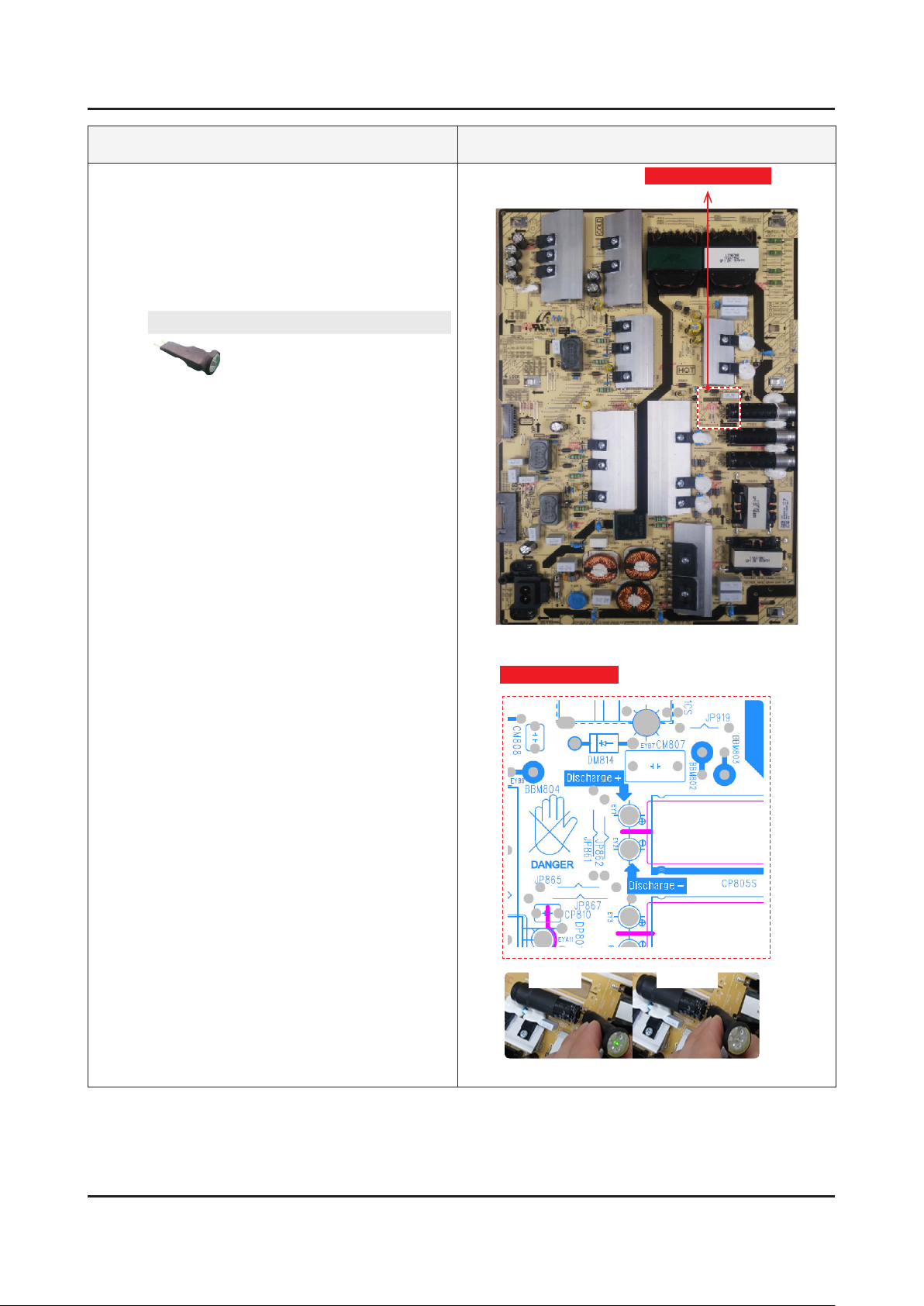
6-2
Discharge Capacitors.
75"•
Before remove SMPS, Must discharge •
capacitors for your safety.
Check discharge point(1st, 2nd block) and •
then, discharge with discharge-Jig.
A/S-DISCHARGE-JIG
BN81-16292A
Measurement point
Measurement point
LED ON LED OFF
<Before discharging> <After discharging>
3-7
3. Disassembly and Reassemble
Description & Screws Picture Description
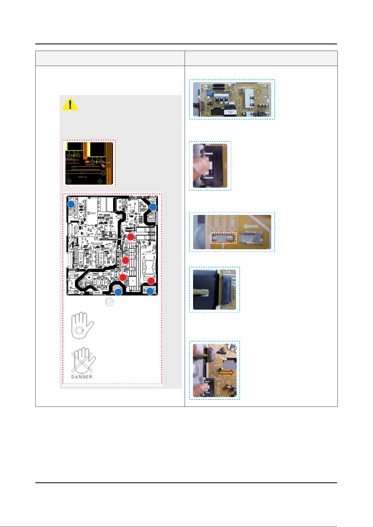
6-3
Remove the DC VSS-PD BOARD.
(Please follow 5 sequence on right.)
CAUTION
Plz discharge SMPS before disconnect SMPS.
And Refer to available touch point.
Before SMPS
disconnect, Use
discharge Jig on
this point for SMPS
discharge.
A
B
A
Remove power connector.1.
Push and hold down BLU Connector Tab to release its 2.
panel lock connection.
Lift to Release the Lock Tab on Upper left side of 3.
Board (Step 5 will assist).
<You can see
B
B
A
silk for touch>
Point A : Can touch (2nd
GND & NO materials)
Point B : Don't touch (1st
Importand materials)
B
A
Locate a notch in insulation sheet (not all models).4.
Use Open Tool in notch to help release & smoothly 5.
slide SMPS Board to the Right. (While pushing BLU
Tab & Releasing Lock Tab)
Loading...