


 Loading...
WARRANTY
Samsung Medison provides the following warranty to the purchaser of this unit.This warranty is valid for a period of one year from the date of installation and covers all problems caused by faulty workmanship or faulty material. Samsung Medison will, as sole and exclusive remedy and at no charge, replace any such defective unit returned to Samsung Medison within the designated warranty period.
The warranty does not cover damages and loss caused by outside factors including, but not limited to, re,ood, storm, tidal wave, lightning, earthquake, theft, abnormal conditions of operation, and intentional destruction of the equipment. Damage caused by equipment relocation is not covered.
The warranty is void in cases where the equipment has been damaged as a result of an accident, misuse, abuse, dropping, or when attempts to modify or alter any part or assembly of the equipment have taken place.
Parts with cosmetic defects or deterioration will not be replaced. Replacement of batteries, training materials, and supplies are not covered.
Samsung Medison will not be responsible for incidental or consequential damages of any kind arising from or connected with the use of the equipment.
Samsung Medison will not be responsible for any loss, damage, or injury resulting from a delay in services rendered under the warranty
This limited warranty is in lieu of all other warranties expressed or implied, including warranties of merchant ability or tness for any particular use. No representative or other person is authorized to represent or assume for Samsung Medison any warranty liability beyond that set forth herein.
Defective equipment shipped from you to Samsung Medison must be packed in the replacement cartons. Shipping and insurance costs are the responsibility of the customer. To return defective material to Samsung Medison contact the Samsung Medison Customer Service Department.
Samsung Medison or a local distributor will make available, upon request, circuit diagrams, a component parts list, descriptions, calibration instructions and other information which will assist your appropriately quali ed technical personnel to repair those parts of the equipment which are designed by Samsung Medison as repairable.
CAUTION: United State federal law restricts this device to sale by or on the order of physicians.
MANUFACTURER : SAMSUNG MEDISON CO., LTD.
42, Teheran-ro 108-gil, Gangnam-gu, Seoul, Korea
Customer Service Department : SAMSUNG MEDISON CO., LTD.
TEL : 82-2-2194-1234 FAX : 82-2-2194-1071
Website: www.samsungmedison.com
EC Representative : SAMSUNG ELECTRONICS (UK) LTD.
Blackbushe Business Park, Saxony Way,
Yateley, Hampshire, GU46 6GG, UK

Diagnostic Ultrasound System
Operation Manual
Version 1.00.00
English
MI68-02334A
PROPRIETRAY INFORMATION AND SOFTWARE LICENSE
The Customer shall keep confidential all proprietary information furnished or disclosed to the Customer by Samsung Medison, unless such information has become part of the public domain through no fault of the Customer. The Customer shall not use such proprietary information, without the prior written consent of Samsung Medison, for any purpose other than the maintenance, repair or operation of the goods.
Samsung Medison’s systems contain Samsung Medison’s proprietary software in machine-readable form. Samsung Medison retains all its rights, title and interest in the software except that purchase of this product includes a license to use the machine-readable software contained in it. The Customer shall not copy, trace, disassemble or modify the software. Transfer of this product by the Customer shall constitute a transfer of this license that shall not be otherwise transferable. Upon cancellation or termination of this contract or return of the goods for reasons other than repair or modification, the Customer shall return to Samsung Medison all such proprietary information.

 Safety Requirements
Classifications:
XXType of protection against electrical shock: Class I
XXDegree of protection against electrical shock (Patient connection): Type BF equipment
XXDegree of protection against harmful ingress of water: Ordinary equipment
XXDegree of safety of application in the presence of a flammable anesthetic material with air or with oxygen or nitrous oxide: Equipment not suitable for use in the presence of a flammable anesthetic mixture with air or with oxygen or nitrous oxide.
XXMode of operation: Continuous operation
Electromechanical safety standards met:
XXMedical Electrical Equipment, Part 1: General Requirements for Basic Safety and Essential Performance IEC 60601-1:2005
XXMedical Electrical Equipment, Part 1-2: General Requirements for Basic Safety and Essential PerformanceCollateral Standard: Electromagnetic Compatibility - Requirements and Tests IEC
60601-1-2:2007
XXMedical Electrical Equipment, Part 1-6: General Requirements for Basic Safety and Essential PerformanceCollateral Standard: Usability IEC 60601-1-6:2006
XXMedical Electrical Equipment, Part 2-37: Particular Requirements for the Basic Safety and Essential Performance of Ultrasonic Medical Diagnostic and Monitoring Equipment IEC60601-2-37:2007
XXMedical Electrical Equipment, Part 1: General Requirements for Safety IEC 60601-1:1988 with
A1:1991 and A2:1995
XXMedical Electrical Equipment, Part 1: General Requirements for Safety - 1 Collateral Standard: Safety Requirement for Medical Electrical Systems IEC 60601-1-1:2000
XXMedical Electrical Equipment, Part 1: General Requirements for Safety - 2 Collateral Standard: Electromagnetic Compatibility - Requirements and Test IEC 60601-1-2:2001, A1:2004
XXMedical Electrical Equipment, Part 1: General Requirements for Safety - 4 Collateral Standard:
Programmable Electrical Medical Systems IEC 60601-1-4: 1996, A1:1999

XXMedical Electrical Equipment, Part 2: Particular Requirements for Safety - 37 Ultrasonic Medical Diagnostic and Monitoring Equipment IEC60601-2-37: 2001 with A1:2004, A2:2005
XXMedical Devices - Application of Risk Management to Medical Devices ISO 14971:2007
XXMedical Electrical Equipment, Part 1: General Requirements for Safety UL60601-1:2003
XXMedical Electrical Equipment - Part 1: General Requirements for Safety CAN/CSA 22.2
No.601.1-M90:1990, with R2003, with R2005
XXBiological Evaluation of Medical Devices ISO10993:2009
XXStandard Means for the Reporting of the Acoustic Output of Medical Diagnostic Ultrasonic Equipment
IEC61157:2007
Declarations
This is the CSA symbol for Canada and United States of America.
This is the manufacturer’s declaration of product compliance with applicable EEC directive(s) and the European notified body.
This is the manufacturer’s declaration of product compliance with applicable EEC directive(s).
This is the GMP symbol that shows that the product complies with the Korean Good
Manufacturing Practice quality regulation system.

 Precautions For Use
Be sure to read this manual thoroughly to familiarize yourself with the operation of the product and the relevant safety information before attempting to use the product.
Keep this manual near the product and refer to it when using the product.
‘Chapter 1. Safety‘ and ‘Chapter 4. Maintenance’, in particular, contain important safety information and must be thoroughly understood.
This manual does not include diagnosis results or opinions. Also, check the reference information for the measured area of the body before using the application’s measurement results in any diagnosis.
This product is an ultrasound diagnosis device and cannot be used with your PC. The manufacturer is not responsible for any problems that may be caused by such attempts.
This product must only be used by persons who are trained and/or certified to operate clinical diagnostic devices. Unqualified persons must not use this product.
The manufacturer is not responsible for any damage to this product caused by user carelessness and/or neglect.
The contents and specifications described in this manual may be changed without notice.
Products that are not manufactured by Samsung Medison are indicated with the trademarks of their respective owners.
The following terms are used to highlight safety precautions that the user must be aware of:
DANGER: Disregarding this instruction may result in death, serious injury, or other dangerous situations.
WARNING: Follow these instructions to prevent a serious accident or damage to property.
CAUTION: Follow these instructions to prevent a minor accident or damage to property.
NOTE: The accompanying information covers an installation, operation, or maintenance procedure that requires careful attention from the user, but has little chance of leading directly to a dangerous situation.
If You Need Assistance
If you need any assistance with the equipment, or the service manual, please contact Samsung Medison‘s Customer Service Department or one of their worldwide customer service representatives immediately.


 Revision History
The revision history of this manual is as follows.
VERSION |
DATE |
NOTE |
|
|
|
v1.00.00-00 |
2012-04-02 |
Initial Release |
|
|
|
Product Upgrade and Manual Update
Upgrades to this product can include upgrades to its hardware or software components. Revised versions of this manual will be published to reflect any upgrades to the product.
Please make sure that your operation manual is appropriate for your product version. If not, please contact Samsung Medison's Customer Service Department.

Table of Contents
Table of Contents – Volume 1
Chapter 1 Safety |
|
Indication for Use....................................................................................................................... |
1-3 |
Safety Information..................................................................................................................... |
1-4 |
Safety Symbols.................................................................................................................................................................... |
1-4 |
Labels...................................................................................................................................................................................... |
1-6 |
Electrical Safety........................................................................................................................... |
1-7 |
Prevention of Electric Shocks......................................................................................................................................... |
1-7 |
ESD........................................................................................................................................................................................... |
1-8 |
EMI............................................................................................................................................................................................ |
1-9 |
EMC ......................................................................................................................................................................................... |
1-9 |
Mechanical Safety.................................................................................................................... |
1-17 |
Moving the Equipment.................................................................................................................................................. |
1-17 |
Precautions for Use.......................................................................................................................................................... |
1-18 |
Biological Safety....................................................................................................................... |
1-20 |
The ALARA Principle........................................................................................................................................................ |
1-20 |
Protecting the Environment................................................................................................... |
1-35 |
Waste Electrical and Electronic Equipment ........................................................................................................... |
1-35 |
Chapter 2 Introduction
Product Specifications............................................................................................................... |
2-3 |
Product Configuration............................................................................................................... |
2-5 |
The Monitor.......................................................................................................................................................................... |
2-6 |
The Control Panel............................................................................................................................................................... |
2-8 |
The Console ....................................................................................................................................................................... |
2-15 |
Peripheral Devices............................................................................................................................................................ |
2-17 |
Probes................................................................................................................................................................................... |
2-20 |
Accessories.......................................................................................................................................................................... |
2-21 |
Optional Functions.......................................................................................................................................................... |
2-22 |
15


 Operation Manual
Chapter 3 Utilities
System Settings.......................................................................................................................... |
3-3 |
General System Settings.................................................................................................................................................. |
3-4 |
General................................................................................................................................................................................... |
3-4 |
Patient..................................................................................................................................................................................... |
3-7 |
Screen Display Settings (Imaging)............................................................................................................................... |
3-8 |
Display.................................................................................................................................................................................... |
3-8 |
Measurement Settings................................................................................................................................................... |
3-11 |
Report................................................................................................................................................................................... |
3-25 |
Anatomy............................................................................................................................................................................... |
3-25 |
Comments........................................................................................................................................................................... |
3-26 |
Annotation.......................................................................................................................................................................... |
3-27 |
Body Marker........................................................................................................................................................................ |
3-31 |
Application.......................................................................................................................................................................... |
3-35 |
Peripheral Device Settings............................................................................................................................................ |
3-37 |
User Defined Keys (Customize Keys)......................................................................................................................... |
3-39 |
Customize Touch Menu.................................................................................................................................................. |
3-42 |
Device................................................................................................................................................................................... |
3-43 |
Connectivity Settings ..................................................................................................................................................... |
3-44 |
DICOM Settings ................................................................................................................................................................ |
3-44 |
Network Settings ............................................................................................................................................................ |
3-55 |
Service................................................................................................................................................................................... |
3-56 |
Help........................................................................................................................................................................................ |
3-56 |
Chapter 4 Maintenance and Storage
Operational Environment......................................................................................................... |
4-3 |
Product Maintenance................................................................................................................ |
4-4 |
Cleaning and disinfecting............................................................................................................................................... |
4-4 |
Fuse Replacement.............................................................................................................................................................. |
4-6 |
Cleaning Air Filters............................................................................................................................................................. |
4-7 |
Accuracy Checks................................................................................................................................................................. |
4-7 |
Information Maintenance......................................................................................................... |
4-8 |
User Settings Backup........................................................................................................................................................ |
4-8 |
Backing Up Patient Information.................................................................................................................................... |
4-8 |
Software................................................................................................................................................................................. |
4-8 |
16

Table of Contents
Chapter 5 Probes
Probes........................................................................................................................................... |
5-3 |
Ultrasound Transmission Gel.......................................................................................................................................... |
5-8 |
Sheaths................................................................................................................................................................................... |
5-9 |
Probe Safety Precautions............................................................................................................................................... |
5-10 |
Cleaning and Disinfecting the Probe........................................................................................................................ |
5-12 |
Biopsy......................................................................................................................................... |
5-20 |
Biopsy Kit Components.................................................................................................................................................. |
5-20 |
Using the Biopsy Kit......................................................................................................................................................... |
5-21 |
Cleaning and Disinfecting the Biopsy Kit................................................................................................................ |
5-23 |
Assembling the Biopsy Kit............................................................................................................................................. |
5-25 |
**Reference Manual
A Reference Manual (English) is supplied with this product.
17

Chapter 1
Safety
Indication for Use............................................. |
1-3 |
|
|
Safety Information........................................... |
1-4 |
|
|
Safety Symbols.......................................................................... |
1-4 |
Labels............................................................................................ |
1-6 |
Electrical Safety................................................ |
1-7 |
|
|
Prevention of Electric Shocks.............................................. |
1-7 |
ESD................................................................................................. |
1-8 |
EMI................................................................................................. |
1-9 |
EMC .............................................................................................. |
1-9 |
Mechanical Safety......................................... |
1-17 |
|
|
Moving the Equipment........................................................ |
1-17 |
Precautions for Use................................................................ |
1-18 |
Biological Safety............................................ |
1-20 |
|
|
The ALARA Principle............................................................. |
1-20 |
Protecting the Environment......................... |
1-35 |
|
|
Waste Electrical and Electronic Equipment ................ |
1-35 |
Chapter 1 Safety

 Indication for Use
The UGEO H60 Diagnostic Ultrasound System and transducers are intended for diagnostic ultrasound imaging and fluid analysis of the human body.
The clinical applications include: Fetal, Abdominal, Pediatric, Small Organ, Neonatal Cephalic, Transrectal, Trans-vaginal, Muscular-Skeletal (Conventional, Superficial), Peripheral vessel.
Contraindications
The UGEO H60 system is not intended for ophthalmic use or any use causing the acoustic beam to pass through the eye.
CAUTION:
XXFederal law restricts this device to sale by or on the order of a physician.
XXThe method of application or use of the device is described in the manual 'Chapter 6. Starting
Diagnosis' and 'Chapter 7. Diagnosis Modes'.
1-3


 Operation Manual

 Safety Information
Please read the following safety information before using this product. It is relevant to the ultrasound system, the probes, the recording devices, and any of the optional equipment.
The product is intended for use by, or by the order of, and under the supervision of, a licensed physician who is qualified for direct use of the medical device.
This equipment should not be used by any healthcare professional or individual who is not properly qualified to operate it. Prolonged use of three-dimensional ultrasound (3D, 4D) by an unqualified individual, such as to produce a commemorative photograph or video of the fetus, may have an adverse effect on the fetus.
Please use the 3D ultrasound diagnostic imaging system for appropriate purposes only, since using it for non-diagnostic purposes such as recording videos of the fetus may adversely affect the fetus.
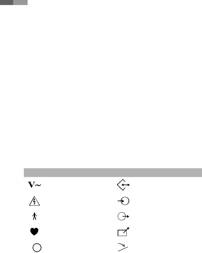
Safety Symbols
The International Electro Technical Commission (IEC) has established a set of symbols for medical electronic equipment, which classify a connection or warn of potential hazards. The classifications and symbols are shown below.
|
|
Symbols |
Description |
Symbols |
Description |
||||||
|
|
|
|
|
|
|
|
|
|
|
|
|
|
|
|
|
|
|
AC (alternating current) voltage source |
|
|
|
Data Input/Output port |
|
|
|
|
|
|
|
|
|
|
|
|
|
|
|
|
|
|
|
Electric shock warning |
|
|
|
Left and right Audio / Video input |
|
|
|
|
|
|
|
|
|
|
|
|
|
|
|
|
|
|
|
Isolated patient connection (Type BF |
|
|
|
Left and right Audio / Video output |
|
|
|
|
|
|
|
|
|
|
||
|
|
|
|
|
|
|
applied part). |
|
|
|
|
|
|
|
|
|
|
|
|
|
|
|
|
|
|
|
|
|
|
|
|
|
|
|
|
|
|
|
|
|
|
|
Isolated patient connection (Type CF |
|
|
|
Remote print output |
|
|
|
|
|
|
|
|
|
|
||
|
|
|
|
|
|
|
|
|
|
||
|
|
|
|
|
|
|
applied part). |
|
|
|
|
|
|
|
|
|
|
|
|
|
|
|
|
|
|
|
|
|
|
|
|
|
|
|
|
|
|
|
|
|
|
|
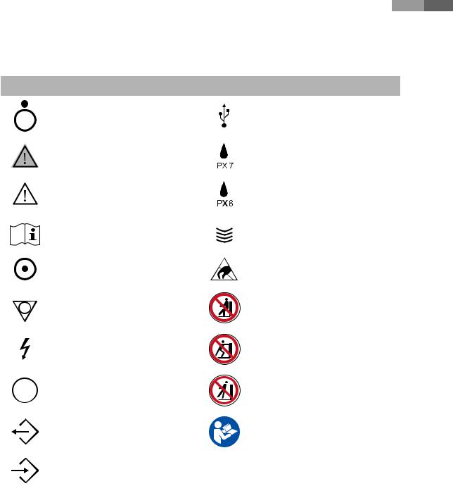
Power switch (Supplies/cuts the power |
|
|
|
Foot switch connector |
|
|
|
|
|
|
|
|
|
|
||
|
|
|
|
|
|
|
for product) |
|
|
|
|
|
|
|
|
|
|
|
|
|
|
|
|
|
|
|
|
|
|
|
|
|
|
|
|
1-4
Chapter 1 Safety
Symbols |
Description |
Symbols |
Description |
||||||||||
|
|
|
|
|
|
|
|
|
|
|
|
|
|
|
|
|
|
|
|
|
|
OFF (Cuts the power to a part of the |
|
|
|
|
USB connector |
|
|
|
|
|
|
|
|
product) |
|
|
|
|
|
|
|
|
|
|
|
|
|
|
|
|
|
|
|
|
|
|
|
|
|
|
|
|
|
|
|
|
|
|
|
|
|
|
|
|
|
WARNING: Follow this information to |
|
|
|
|
Protection against the effects of |
|
|
|
|
|
|
|
|
prevent a serious accident or damage to |
|
|
|
|
|
|
|
|
|
|
|
|
|
|
|
|
|
immersion |
|
|
|
|
|
|
|
|
|
property. |
|
|
|
|
|
|
|
|
|
|
|
|
|
|
|
|
|
||
|
|
|
|
|
|
|
|
|
|
|
|
|
|
|
|
|
|
|
|
|
|
|
|
|
|
|
|
|
|
|
|
|
|
|
|
CAUTION: Hazards or unsafe practices |
|
|
|
|
Protection against long periods of |
|
|
|
|
|
|
|
|
that may result in minor personal injury |
|
|
|
|
|
|
|
|
|
|
|
|
|
|
|
|
|
immersion under pressure |
|
|
|
|
|
|
|
|
|
or property damage. |
|
|
|
|
|
|
|
|
|
|
|
|
|
|
|
|
|
||
|
|
|
|
|
|
|
|
|
|
|
|
|
|
|
|
|
|
|
|
|
|
|
|
|
|
|
|
|
|
|
|
|
|
|
|
Refer to the operation manual |
|
|
|
|
Probe connector |
|
|
|
|
|
|
|
|
|
|
|
|
||
|
|
|
|
|
|
|
|
|
|
|
|
||
|
|
|
|
|
|
|
|
|
|
|
|
|
|
|
|
|
|
|
|
|
|
ON (Supplies power to a part of the |
|
|
|
|
ESD (Electrostatic discharge) caution |
|
|
|
|
|
|
|
|
product) |
|
|
|
|
symbol |
|
|
|
|
|
|
|
|
|
|
|
|
|
|
|
|
|
|
|
|
|
|
Identifies an equipotential ground. |
|
|
|
|
Do not sit on control panel |
|
|
|
|
|
|
|
|
|
|
|
|
||
|
|
|
|
|
|
|
|
|
|
|
|
||
|
|
|
|
|
|
|
|
|
|
|
|
|
|
|
|
|
|
|
|
|
|
Indicates dangerous voltages over |
|
|
|
|
Do not push the product |
|
|
|
|
|
|
|
|
1000V AC or over 1500V DC. |
|
|
|
|
|
|
|
|
|
|
|
|
|
|
|
|
|
|
|
|
|
|
|
|
|
|
|
|
|
|
|
|
|
|
|
|
|
|
|
|
|
Protective earth connected to |
|
|
|
|
|
|
|
|
|
|
|
|
|
|
|
|
|
|
|
|
|
|
|
|
|
|
|
conductive parts of Class I equipment |
|
|
|
|
Do not lean against the product |
|
|
|
|
|
|
|
|
for safety purposes. |
|
|
|
|
|
|
|
|
|
|
|
|
|
|
|
|
|
|
|
|
|
|
|
|
|
|
|
|
|
|
|
|
|
|
|
|
|
|
|
|
|
Data Output port |
|
|
|
|
Follow the operation manual |
|
|
|
|
|
|
|
|
|
|
|
|
|
|
|
|
|
|
|
|
|
|
Data Input port |
|
|
|
|
|
|
|
|
|
|
|
|
|
|
|
|
|
|
|
1-5


 Operation Manual
Labels
Warning and caution labels that contain information and instructions concerning the protection of the product can be found on the exterior of the product.
[Label 1. ID label]
[Label 2. Cautions on ‘TIP-OVER’]
[Label 3. Probe ID Label]
[Label 4. Probe label]
1-6

Chapter 1 Safety

 Electrical Safety
This equipment has been verified as a Class I device with Type BF applied parts.
Prevention of Electric Shocks
Additional equipment connected to medical electrical equipment must comply with the respective IEC standards (e.g. IEC60950/EN60950 for data processing equipment, IEC60601-1/EN60601-1 for medical devices). Furthermore, all configurations shall comply with the requirements for medical electrical systems (see IEC60601-1-1/EN60601-1-1). Anybody connecting additional equipment to signal input and output ports of medical electrical equipment should make sure that the equipment complies with IEC60601-1-1/EN60601-1-1.
WARNING:
XXElectric shock may result if this system, including all of its externally mounted recording and monitoring devices, is not properly grounded.
XXNever open the cover of the product. Hazardous voltages are present inside All internal adjustments and replacements must be made by qualified Samsung Medison Customer Support Department personnel.
XXAlways check the product’s housing, cables, cords, and plugs before using the product Disconnect the power source and do not use the equipment if the housing is damaged such as cracked, and chipped, or if the cable is worn.
XXAlways disconnect the system from the wall outlet prior to cleaning the system.
XXAll patient contact devices, such as probes and ECG leads, must be removed from the patient prior to application of a high voltage defibrillation pulse.
XXThe use of flammable anesthetic gas or oxidizing gases (N2O) should be avoided. There is a risk of explosion.
XXAvoid installing the system in such a way that it is difficult for the operator to disconnect it from the power source.
XXDo not use HF surgical equipment with the system. Any malfunctions in the HF surgical equipment may result in burns to the patient.
XXThe System must only be connected to a supply mains with protective earth to avoid risk of electric shock.
1-7


 Operation Manual
CAUTION:
XXThe system has been designed for 100-240VAC; you should select the input voltage of any connected printer and VCR. Prior to connecting a peripheral power cord, verify that the voltage indicated on the power cord matches the voltage rating of the peripheral device.
XXAn isolation transformer protects the system from power surges. The isolation transformer continues to operate when the system is in standby.
XXDo not immerse the cable in liquids. Cables are not waterproof.
XXThe auxiliary socket outlets installed on this system are rated 100-240VAC with maximum total load of 150VA. Use these outlets only for supplying power to equipment that is intended to be part of the ultrasound system. Do not connect additional multiple-socket outlets or extension cords to the system.
XXDo not connect any peripheral devices that are not listed in this manual to the auxiliary socket outlet of the system. It may cause an electrical hazard.
XXDo not touch SIP/SOP and the patient simultaneously. There is a risk of electric shock from leakage current.
ESD
Electrostatic discharge (ESD), commonly referred to as a static shock, is a naturally occurring phenomenon. ESD is most prevalent during conditions of low humidity, which can be caused by heating or air conditioning. The static shock or ESD is a discharge of the electrical energy build-up from a charged individual to a less or non-charged individual or object. An ESD occurs when an individual with an electrical energy build-up comes into contact with conductive objects such as metal doorknobs, file cabinets, computer equipment, and even other individuals.
CAUTION:
XXThe level of electrical energy discharged from a system user or patient to an ultrasound system can be significant enough to cause damage to the system or probes.
XXAlways perform the pre-ESD preventive procedures before using connectors marked with the ESD warning label.
−− Apply anti-static spray to carpets or linoleum. −− Use anti-static mats.
−− Ground the product to the patient table or bed.
XXIt is highly recommended that the user be given training on ESD-related warning symbols and preventive procedures.
1-8

Chapter 1 Safety
EMI
Although this system has been manufactured in compliance with existing EMI (ElectroMagnetic Interface) requirements, use of this system in the presence of an electromagnetic field can cause degradation of the ultrasound image or product damage.
If this occurs often, Samsung Medison suggests a review of the environment in which the system is being used, to identify possible sources of radiated emissions. These emissions could be from other electrical devices used within the same room or an adjacent room. Communication devices such as cellular phones and pagers can cause these emissions.The existence of radios,TVs, or microwave transmission equipment nearby can also cause interference.
CAUTION: In cases where EMI is causing disturbances, it may be necessary to relocate this system.
EMC
The testing for EMC(Electromagnetic Compatibility) of this system has been performed according to the international standard for EMC with medical devices (IEC60601-1-2). This IEC standard was adopted in Europe as the European norm (EN60601-1-2).
Guidance and Manufacturer’s Declaration - Electromagnetic Emission
This product is intended for use in the electromagnetic environment specified below. The customer or the user of this product should ensure that it is used in such an environment.
Emission test |
Compliance |
Electromagnetic environment - guidance |
|
|
|
|
|
RF Emission |
|
The Ultrasound System uses RF energy only for its internal |
|
Group 1 |
functions. Therefore, its RF emissions are very low and are not |
||
CISPR 11 |
|||
|
likely to cause any interference in nearby electronic equipment. |
||
|
|
||
|
|
|
|
RF Emission |
Class B |
|
|
CISPR 11 |
|
||
|
The Ultrasound System is suitable for use in all establishments, |
||
|
|
||
Harmonic Emission |
|
||
Class A |
including domestic establishments and those directly |
||
IEC 61000-3-2 |
connected to the public low-voltage power supply network |
||
|
|||
|
|
that supplies building used for domestic purposes. |
|
Flicker Emission |
Complies |
||
|
|||
IEC 61000-3-3 |
|
||
|
|
||
|
|
|
1-9


 Operation Manual
Approved Cables, Transducers and Accessories for EMC
Approved Cable for Electromagnetic Compliance
Cables connected to this product may affect its emissions; use only the cable types and lengths listed in the table below.
Cable |
Type |
Length |
|
|
|
VGA |
Shielded |
Normal |
|
|
|
USB |
Shielded |
Normal |
|
|
|
LAN(RJ45) |
Twisted pair |
Any |
|
|
|
S-Video |
Shielded |
Normal |
|
|
|
Foot Switch |
Shielded |
< 3m |
|
|
|
e-Motion Marker |
Shielded |
< 3m |
|
|
|
Audio R.L |
Shielded |
Normal |
|
|
|
Parallel |
Shielded |
Normal |
|
|
|
HDMI |
Shielded |
Normal |
|
|
|
Probes
Probes listed in‘Chapter 5. Probes’meet the Group 1 Class B requirements of the CISPR 11 standard.
Approved Accessories for Electromagnetic Compliance
Accessories used with this product may affect its emissions.
CAUTION: When connecting a VCR or other customer-supplied accessory to the system, it is the user’s responsibility to ensure the electromagnetic compatibility of the system. Only use devices that are compliant with CISPR 11 or CISPR 22, CLASS B.
1-10

Chapter 1 Safety
Immunity test |
IEC 60601 Test level |
Compliance level |
Electromagnetic |
|
environment - guidance |
||||
|
|
|
||
|
|
|
|
|
|
|
|
Floors should be wood, |
|
Electrotatic |
±6KV Contact |
±6KV Contact |
concrete or ceramic tile. |
|
discharge (ESD) |
If floors are covered with |
|||
|
|
|||
|
±8KV air |
±8KV air |
synthetic material, the |
|
IEC 61000-4-2 |
relative humidity should be |
|||
|
|
|||
|
|
|
at least 30%. |
|
|
|
|
|
|
Electrical fast |
±2KV |
±2KV |
Mains power quality |
|
transient/burst |
for power supply lines |
for power supply lines |
should be that of a typical |
|
|
±1KV |
±1KV |
commercial or hospital |
|
IEC 61000-4-4 |
for input/output lines |
for input/output lines |
environment. |
|
|
|
|
|
|
Surge |
±1KV differential mode |
±1KV differential mode |
Mains power quality |
|
should be that of a typical |
||||
|
|
|
||
IEC 61000-4-5 |
±2KV common mode |
±2KV common mode |
commercial or hospital |
|
environment. |
||||
|
|
|
||
|
|
|
|
|
|
<5% Uт for 0.5 cycles |
<5% Uт for 0.5 cycles |
Mains power quality |
|
|
(>95% dip in Uт) |
(>95% dip in Uт) |
should be that of a typical |
|
Voltage dips, short |
|
|
commercial or hospital |
|
interruptions and |
40% Uт for 5 cycles |
40% Uт for 5 cycles |
environment. If the user |
|
voltage variations |
(60% dip in Uт) |
(60% dip in Uт) |
of this product requires |
|
on power supply |
|
|
continued operation during |
|
input lines |
70% Uт for 25 cycles |
70% Uт for 25 cycles |
power mains interruptions, |
|
|
(30% dip in Uт) |
(30% dip in Uт) |
it is recommended that this |
|
IEC 61000-4-11 |
|
|
product be powered from |
|
|
<5% Uт for 5 s |
<5% Uт for 5 s |
an uninterruptible power |
|
|
(<95% dip in Uт) |
(<95% dip in Uт) |
supply or a battery. |
|
|
|
|
|
|
Power frequency |
3 A/m |
3 A/m |
Power frequency magnetic |
|
(50/60Hz) magnetic |
|
|
fields should be at levels |
|
field |
|
|
characteristic of a typical |
|
|
|
|
location in a typical |
|
IEC 61000-4-8 |
|
|
commercial or hospital |
|
|
|
|
environment. |
|
|
|
|
|
NOTE: Uт is the A.C. mains voltage prior to application of the test level.
1-11


 Operation Manual
Immunity test |
IEC 60601 |
Compliance |
|
|
Electromagnetic |
test level |
level |
|
|
environment - guidance |
|
|
|
|
|||
|
|
|
|
|
|
Conducted RF |
3 Vrms |
0.01 V |
Portable and mobile RF communications |
||
IEC 61000-4-6 |
150 kHz |
|
equipment should be used no closer to any part of |
||
|
to 80 MHz |
|
the Ultrasound System, including cables, than the |
||
|
|
|
recommended separation distance calculated from |
||
|
|
|
the equation applicable to the frequency of the |
||
|
|
|
transmitter. |
||
|
|
|
Recommended separation distance |
||
|
|
|
|
|
|
|
|
|
|
|
|
80MHz to 800MHz |
|
|
|
|
|
|
|
|
|
|
|
|
|
800MHz to 2.5GHz |
|
|
|
|
|
|
|
Radiated RF |
3 V/m |
3 V/m |
Where P is the maximum output power rating |
|||
IEC 61000-4-3 |
80 MHz |
|
of the transmitter in watts (W) according to |
|||
|
to 2.5 GHz |
|
the transmitter manufacturer and d is the |
|||
|
|
|
recommended separation distance in meters (m). |
|||
|
|
|
Field strengths from fixed RF transmitters, as |
|||
|
|
|
determined by an electromagnetic site survey, a |
|||
|
|
|
should be less than the compliance level in each |
|||
|
|
|
frequency range. b |
|||
|
|
|
Interference may occur in the vicinity of |
|||
|
|
|
equipment marked with the following symbol : |
|||
NOTE 1: At 80MHz and 800MHz, the higher frequency range applies.
NOTE 2: These guidelines may not apply in all situations. Electromagnetic propagation is affected by absorption and reflection from structures, objects and people.
aField strengths from fixed transmitters, such as base stations for radio (cellular/cordless) telephones and land mobile radios, amateur radio, AM and FM radio broadcast and TV broadcast cannot be predicted theoretically with accuracy. To assess the electromagnetic environment due to fixed RF transmitters, an electromagnetic site survey should be considered. If the measured field strength in the location in which the Ultrasound System is used exceeds the applicable RF compliance
level above, the Ultrasound System should be observed to verify normal operation. If abnormal performance is observed, additional measures may be necessary, such as re-orienting or relocating the Ultrasound System, or using a shielded location with a higher RF shielding effectiveness and filter attenuation.
bOver the frequency range 150kHz to 80MHz, field strengths should be less than V1 V/m.
1-12
Loading...