


 Loading...
LED TV
Chassis : UWK50
Model : UN32J5500AF
UN40J5500AF
UN48J5500AF
UN50J5500AF
SERVICE Manual 
LED TV |
|
Contents |
|
|
|
1. Precautions
2. Product specifications
3. Disassembly and Reassembly
4. Troubleshooting
5. Wiring Diagram
UN**J5500AF
|
|
Contents |
|
1. Precautions............................................................................................................... |
1-1 |
||
1-1. |
Safety Precautions.......................................................................................................... |
1-1 |
|
|
1-1-1. Warnings............................................................................................................... |
1-1 |
|
|
1-1-2. Servicing the LED TV........................................................................................... |
1-1 |
|
|
1-1-3. |
Fire and Shock Hazard......................................................................................... |
1-1 |
|
1-1-4. |
Product Safety Notices......................................................................................... |
1-2 |
1-2. |
Servicing Precautions...................................................................................................... |
1-3 |
|
|
1-2-1. |
General Servicing Precautions............................................................................. |
1-3 |
1-3. |
Static Electricity Precautions........................................................................................... |
1-4 |
|
1-4. |
Installation Precautions................................................................................................... |
1-5 |
|
2. Product Specifications............................................................................................ |
2-1 |
||
2-1. |
Product information......................................................................................................... |
2-1 |
|
2-2. |
Product specification....................................................................................................... |
2-2 |
|
|
2-2-1. |
Detailed Specifications......................................................................................... |
2-2 |
|
2-2-2. |
Specifications....................................................................................................... |
2-7 |
2-3. |
Accessories.................................................................................................................... |
2-8 |
|
3. Disassembly and Reassembly................................................................................ |
3-1 |
3-1. Disassembly and Reassembly........................................................................................ |
3-1 |
4. Troubleshooting....................................................................................................... |
4-1 |
4-1. Troubleshooting............................................................................................................... |
4-1 |
4-2. How to Check Fault Symptom......................................................................................... |
4-2 |
4-2-1. Video..................................................................................................................... |
4-2 |
4-2-2. Bluetooth / WIFI Module....................................................................................... |
4-3 |
4-2-3. SMPS................................................................................................................... |
4-5 |
4-2-4. Jog Function Control............................................................................................ |
4-9 |
4-3. Factory Mode Adjustments............................................................................................ |
4-10 |
4-3-1. Detail Factory Option.......................................................................................... |
4-10 |
4-3-2. Entering Factory Mode....................................................................................... |
4-12 |
4-3-3. Factory Data....................................................................................................... |
4-13 |
4-4. White Balance............................................................................................................... |
4-29 |
4-4-1. Calibration.......................................................................................................... |
4-29 |
4-4-2. Service Adjustment............................................................................................. |
4-29 |
4-4-3. Adjustment.......................................................................................................... |
4-31 |
4-5. Software Upgrade......................................................................................................... |
4-32 |
4-5-1. By USB............................................................................................................... |
4-32 |
4-5-2. By Online............................................................................................................ |
4-32 |
4-5-3. Alternative Software (Backup)............................................................................ |
4-32 |
4-6. The Dimension of J5500 Models................................................................................... |
4-33 |
5. Wiring Diagram......................................................................................................... |
5-1 |
|
5-1. Wiring Diagram................................................................................................................ |
5-1 |
|
5-2. |
Connector........................................................................................................................ |
5-2 |
5-3. |
Connector Functions....................................................................................................... |
5-5 |
5-4. |
Cables............................................................................................................................. |
5-6 |
5-5. The Types of Module....................................................................................................... |
5-7 |
|
ANNEX. Exploded View & Part List [UN32J5500AFXZA TS01]...................... |
ANNEX-1 |
|
1-1. |
Exploded View....................................................................................................... |
ANNEX-1 |
|
1-1-1. Parts List..................................................................................................... |
ANNEX-1 |
2-1. |
Electrical Parts List................................................................................................ |
ANNEX-2 |
ANNEX. Exploded View & Part List [UN40J5500AFXZA TS01]...................... |
ANNEX-1 |
|
1-1. |
Exploded View....................................................................................................... |
ANNEX-1 |
|
1-1-1. Parts List..................................................................................................... |
ANNEX-1 |
2-1. |
Electrical Parts List................................................................................................ |
ANNEX-2 |
ANNEX. Exploded View & Part List [UN48J5500AFXZA TS01]...................... |
ANNEX-1 |
|
1-1. |
Exploded View....................................................................................................... |
ANNEX-1 |
|
1-1-1. Parts List..................................................................................................... |
ANNEX-1 |
2-1. |
Electrical Parts List................................................................................................ |
ANNEX-2 |
ANNEX. Exploded View & Part List [UN50J5500AFXZA II01]......................... |
ANNEX-1 |
|
1-1. |
Exploded View....................................................................................................... |
ANNEX-1 |
|
1-1-1. Parts List..................................................................................................... |
ANNEX-1 |
2-1. |
Electrical Parts List................................................................................................ |
ANNEX-2 |

This Service Manual is a property of Samsung Electronics Co.,Ltd.
Any unauthorized use of Manual can be punished under applicable International and/or domestic law.
© 2015 Samsung Electronics Co.,Ltd. All rights reserved.
Printed in Korea
1. Precautions
1. Precautions
1-1. Safety Precautions
Follow these safety, servicing and ESD precautions to prevent damage and to protect against potential hazards such as electrical shock.
1-1-1. Warnings
For continued safety, do not attempt to modify the circuit board.
WARNING |
Disconnect the AC power and DC power jack before servicing. |
|
1-1-2. Servicing the LED TV
1.When servicing the LED TV, Disconnect the AC line cord from the AC outlet.
2.It is essential that service technicians have an accurate voltage meter available at all times. Check the calibration of this meter periodically.
1-1-3. Fire and Shock Hazard
Before returning the monitor to the user, perform the following safety checks:
1.Inspect each lead dress to make certain that the leads are not pinched or that hardware is not lodged between the chassis and other metal parts in the monitor.
2.Inspect all protective devices such as nonmetallic control knobs, insulating materials, cabinet backs, adjustment and compartment covers or shields, isolation resistorcapacitor networks, mechanical insulators, etc.
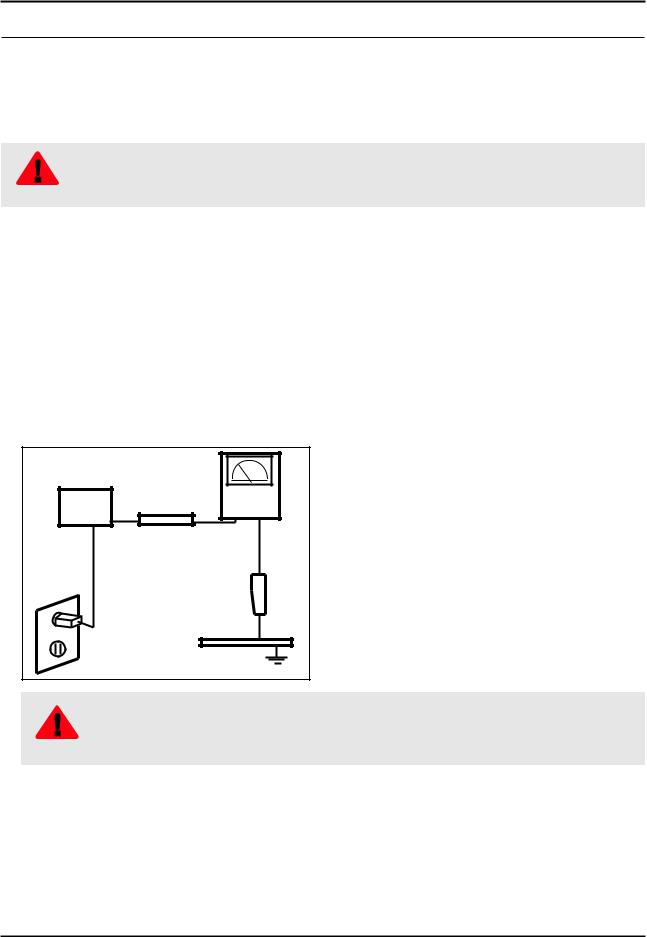
3.Leakage Current Hot Check:
(READING SHOULD) |
|
|
NOT BE ABOVE 0.5mA |
LEAKAGE |
|
DEVICE |
||
CURRENT |
||
UNDER |
||
TESTER |
||
TEST |
||
|
||
TEST ALL |
|
|
EXPOSED METAL |
|
|
SURFACES |
|
|
2-WIRE CORD |
|
|
ALSO TEST WITH |
|
|
PLUG REVERSED |
EARTH |
|
(USING AC ADAPTER |
||
PLUG AS REQUIRED) |
GROUND |
Do not use an isolation transformer during this test.
|
Use a leakage current tester or a metering system that complies with American National Standards |
|
WARNING |
Institute (ANSI C101.1, Leakage Current for Appliances), and Underwriters Laboratories (UL |
|
Publication UL1410, 59.7). |
||
|
4.With the unit completely reassembled, plug the AC line cord directly into a 120V AC outlet. With the unit’s AC switch first in the ON position and then OFF, measure the current between a known earth ground (metal water pipe, conduit, etc.) and all exposed metal parts, including: metal cabinets, screwheads and control shafts.
The current measured should not exceed 0.5 milliamp.
Reverse the power-plug prongs in the AC outlet and repeat the test.
1-1

1. Precautions
1-1-4. Product Safety Notices
Some electrical and mechanical parts have special safetyrelated characteristics which are often not evident from visual inspection. The protection they give may not be obtained by replacing them with components rated for higher voltage, wattage, etc. Parts that have special safety characteristics are identified by  on schematics and parts lists. A substitute replacement that does not have the same safety characteristics as the recommended replacement part might create shock, fire and/or other hazards. Product safety is under review continuously and new instructions are issued whenever appropriate.
1-2

1. Precautions
1-2. Servicing Precautions
An electrolytic capacitor installed with the wrong polarity might explode.
WARNING
Before servicing units covered by this service manual, read and follow the Safety Precautions section of
this manual.
CAUTION
If unforeseen circumstances create conflict between the following servicing precautions and any of the
safety precautions, always follow the safety precautions.
NOTE
1-2-1. General Servicing Precautions
1.Always unplug the unit’s AC power cord from the AC power source and disconnect the DC Power Jack before attempting to: (a) remove or reinstall any component or assembly, (b) disconnect PCB plugs or connectors, (c) connect a test component in parallel with an electrolytic capacitor.
2.Some components are raised above the printed circuit board for safety. An insulation tube or tape is sometimes used. The internal wiring is sometimes clamped to prevent contact with thermally hot components. Reinstall all such elements to their original position.
3.After servicing, always check that the screws, components and wiring have been correctly reinstalled. Make sure that the area around the serviced part has not been damaged.
4.Check the insulation between the blades of the AC plug and accessible conductive parts (examples: metal panels, input terminals and earphone jacks).
5.Insulation Checking Procedure: Disconnect the power cord from the AC source and turn the power switch ON. Connect an insulation resistance meter (500 V) to theblades of the AC plug. The insulation resistance between each blade of the AC plug and accessible conductive parts (see above) should be greater than 1 megohm.
6.Always connect a test instrument’s ground lead to the instrument chassis ground before connecting the positive lead; always remove the instrument’s ground lead last.
1-3
1. Precautions
1-3. Static Electricity Precautions
Some semiconductor (solid state) devices can be easily damaged by static electricity. Such components are commonly called Electrostatically Sensitive Devices (ESD). Examples of typical ESD are integrated circuits and some field-effect transistors. The following techniques will reduce the incidence of component damage caused by static electricity.
1.Immediately before handling any semiconductor components or assemblies, drain the electrostatic charge from your body by touching a known earth ground. Alternatively, wear a discharging wrist-strap device. To avoid a shock hazard, be sure to remove the wrist strap before applying power to the monitor.
2.After removing an ESD-equipped assembly, place it on a conductive surface such as aluminum foil to prevent accumulation of an electrostatic charge.
3.Do not use freon-propelled chemicals. These can generate electrical charges sufficient to damage ESDs.
4.Use only a grounded-tip soldering iron to solder or desolder ESDs.
5.Use only an anti-static solder removal device. Some solder removal devices not classified as “anti-static” can generate electrical charges sufficient to damage ESDs.
6.Do not remove a replacement ESD from its protective package until you are ready to install it. Most replacement ESDs are packaged with leads that are electrically shorted together by conductive foam, aluminum foil or other conductive materials.
7.Immediately before removing the protective material from the leads of a replacement ESD, touch the protective material to the chassis or circuit assembly into which the device will be installed.
Be sure no power is applied to the chassis or circuit and observe all other safety precautions.
CAUTION
8.Minimize body motions when handling unpackaged replacement ESDs. Motions such as brushing clothes together, or lifting your foot from a carpeted floor can generate enough static electricity to damage an ESD.
1-4
1. Precautions
1-4. Installation Precautions
1.For safety reasons, more than a people are required for carrying the product.
2.Keep the power cord away from any heat emitting devices, as a melted covering may cause fire or electric shock.
3.Do not place the product in areas with poor ventilation such as a bookshelf or closet. The increased internal temperature may cause fire.
4.Bend the external antenna cable when connecting it to the product. This is a measure to protect it from being exposed to moisture. Otherwise, it may cause a fire or electric shock.
5.Make sure to turn the power off and unplug the power cord from the outlet before repositioning the product. Also check the antenna cable or the external connectors if they are fully unplugged. Damage to the cord may cause fire or electric shock.
6.Keep the antenna far away from any high-voltage cables and install it firmly. Contact with the highvoltage cable or the antenna falling over may cause fire or electric shock.
7.When installing the product, leave enough space (0.4m) between the product and the wall for ventilation purposes.
A rise in temperature within the product may cause fire.
8.If an equipment is provided with a replaceable battery, and if replacement by an incorrect type could result in an explosion (for example, with some lithium batteries), the following applies:
•Risk of explosion if battery is replaced by an incorrect type dispose of used batteries according to the instructions.
•Do not dispose of batteries in a fire.
•Do not short circuit, disassemble or overheat the batteries.
CAUTION • Danger of explosion if battery is incorrectly replaced. Replace only with the same or equivalent type.
•Do not be exposed to excessive heat such as sunshine, fire or the like.
1-5
2. Product specifications
2. Product Specifications
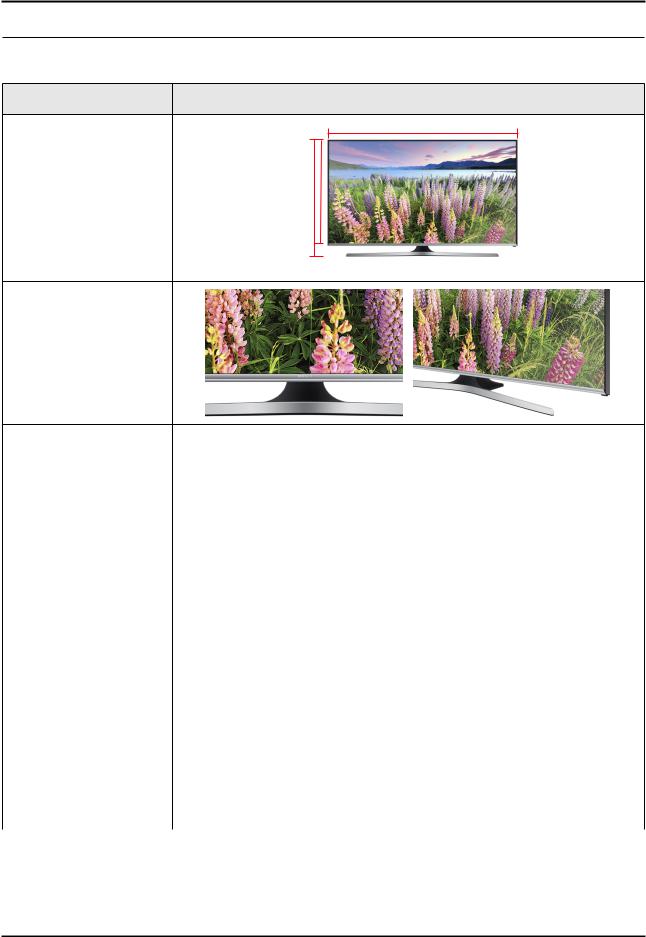
2-1. Product information
Model |
UN**J5500AF |
W
Front View |
H |
* W : Width H : High
Detail View
Color |
|
Front Color : BLACK, Stand Color : LIGHT TITAN (HAIRLINE) |
||
|
|
|
|
|
|
32" |
With Stand |
721.4 x 471.6 x 207.6 mm / 28.40 x 18.57 x 8.17 inches |
|
|
|
|
||
|
Without Stand |
721.4 x 424.8 x 66.6 mm / 28.40 x 16.72 x 2.62 inches |
||
|
|
|||
|
|
|
|
|
|
40" |
With Stand |
907.6 x 585.6 x 288.1 mm / 35.73 x 23.06 x 11.34 inches |
|
|
|
|
||
Dimensions |
Without Stand |
907.6 x 529.7 x 66.9 mm / 35.73 x 20.85 x 2.63 inches |
||
|
||||
|
|
|
||
(W x H x D) |
48" |
With Stand |
1076.1 x 681.3 x 310.5 mm / 42.37 x 26.82 x 12.22 inches |
|
|
||||
|
|
|
||
|
Without Stand |
1076.1 x 624.4 x 67.1 mm / 42.36 x 24.58 x 2.64 inches |
||
|
|
|||
|
|
|
|
|
|
50" |
With Stand |
1117.8 x 703.6 x 310.5 mm / 44.00 x 27.70 x 12.22 inches |
|
|
|
|
||
|
Without Stand |
1117.8 x 647.8 x 67.5 mm / 44.00 x 25.50 x 2.65 inches |
||
|
|
|||
|
|
|
|
|
|
32" |
With Stand |
5.1 kg / 11.24 lbs |
|
|
|
|
||
|
Without Stand |
4.7 kg / 10.36 lbs |
||
|
|
|||
|
|
|
|
|
|
40" |
With Stand |
8.6 kg / 18.96 lbs |
|
|
|
|
||
Weight |
Without Stand |
7.7 kg / 16.98 lbs |
||
|
||||
|
|
|
||
48" |
With Stand |
12.3 kg / 27.17 lbs |
||
|
||||
|
|
|
||
|
Without Stand |
11.3 kg / 27.91 lbs |
||
|
|
|||
|
|
|
|
|
|
50" |
With Stand |
13.4 kg / 29.54 lbs |
|
|
|
|
||
|
Without Stand |
12.4 kg / 27.33 lbs |
||
|
|
|||
|
|
|
|
|
2-1
2. Product specifications
2-2. Product specification
2-2-1. Detailed Specifications
 NOTE
NOTE
Design and specifications are subject to change without prior notice.
|
Item |
UN**J5500AFXZA |
|
|
|
General Information |
Product |
LED |
|
|
|
|
Series |
5 |
|
|
|
|
Country |
UNITED STATES |
|
|
|
Display |
Screen Size |
32"/40"/48"/50" |
|
Resolution |
1,920 x 1,080 |
|
|
|
|
Ultra Clear Panel |
N/A |
|
|
|
Video |
Motion Refresh Rate |
60 |
|
|
|
|
Dynamic Contrast Ratio |
Mega Contrast |
|
|
|
|
Micro Dimming |
Micro Dimming Pro |
|
|
|
|
Precision Black (Local Dimming) |
N/A |
|
|
|
|
Nano Crystal Color |
N/A |
|
|
|
|
Wide Color Enhancer (Plus) |
Yes |
|
|
|
|
PurColor |
N/A |
|
|
|
|
Auto Depth Enhancer |
N/A |
|
|
|
|
Contrast Enhancer |
N/A |
|
|
|
|
Auto Motion Plus |
N/A |
|
|
|
|
Film Mode |
Yes |
|
|
|
|
Peak Illuminator |
N/A |
|
|
|
Audio |
Dolby Digital Plus |
Yes |
|
|
|
|
Virtual Surround |
DTS Studio Sound |
|
|
|
|
DTS Codec |
DTS Premium Sound 5.1 |
|
|
|
|
3D Sound |
N/A |
|
|
|
|
Sound Customizer |
N/A |
|
|
|
|
Sound Output (RMS) |
20W(L:10W, R:10W) |
|
|
|
|
Speaker Type |
2CH(Down Firing + Base Reflex) |
|
|
|
|
Woofer |
N/A |
|
|
|
|
HD Audio |
Yes |
|
|
|
|
Wallmount Sound Mode |
Yes |
|
|
|
|
Multiroom Link |
Yes |
|
|
|
Smart TV |
Samsung SMART TV |
Yes |
|
|
|
|
Apps |
Yes |
|
|
|
|
|
|
2-2

|
|
2. Product specifications |
|
|
|
|
|
|
|
Item |
UN**J5500AFXZA |
|
|
|
Smart TV |
Game |
N/A |
|
|
|
|
Multi-Link Screen |
N/A |
|
|
|
|
ACR (Advertisement) |
Yes |
|
|
|
|
Info Widget |
N/A |
|
|
|
|
Vertical Enhancement |
Yes |
|
|
|
Smart Interaction |
Voice Interaction |
N/A |
|
|
|
|
Voice Control |
N/A |
|
|
|
|
Face recognition |
N/A |
|
|
|
|
Motion control |
N/A |
|
|
|
Smart Convergence |
TV to Mobile - Mirroring |
Yes |
|
|
|
|
Mobile to TV - Mirroring, DLNA |
Yes |
|
|
|
|
RVU |
Yes |
|
|
|
|
Samsung SMART View |
Yes |
|
|
|
|
Wireless TV On - WOL |
Yes |
|
|
|
|
Notification - BLE |
Yes |
|
|
|
|
Briefing On TV |
Yes |
|
|
|
|
WiDi |
N/A |
|
|
|
|
WiFi Direct |
Yes |
|
|
|
Tuner/Broadcasting |
Digital Broadcasting |
ATSC / Clear QAM |
|
|
|
|
2 Tuner |
N/A |
|
|
|
|
CI/CI+/2CI+ |
N/A |
|
|
|
|
Analog Tuner |
Yes |
|
|
|
|
MHP / MHEG / HbbTV / ACAP / GINGA / |
N/A |
|
OHTV |
|
|
|
|
Connectivity |
HDMI |
3 |
|
|
|
|
USB |
2 |
|
|
|
|
Component In (Y/Pb/Pr) |
1 |
|
|
|
|
Composite In (AV) |
1 (Common Use for Component Y) |
|
|
|
|
Ethernet (LAN) |
1 |
|
|
|
|
Headphone |
N/A |
|
|
|
|
Audio Out (Mini Jack) |
1 |
|
|
|
|
Digital Audio Out (Optical) |
1 |
|
|
|
|
RF In (Terrestrial / Cable input / Satellite |
1/1(Common Use for Terrestrial)/0 |
|
input) |
|
|
|
|
|
Ex-Link ( RS-232C ) |
Yes |
|
|
|
|
IR Out |
N/A |
|
|
|
|
CI Slot |
N/A |
|
|
|
|
|
|
2-3

2. Product specifications
|
Item |
UN**J5500AFXZA |
|
|
|
Connectivity |
Scart |
N/A |
|
|
|
|
MHL |
Yes |
|
|
|
|
Dongle Ready (3G / LTE) |
N/A |
|
|
|
|
HDMI 3D Auto Setting |
N/A |
|
|
|
|
HDMI A / Return Ch. Support |
Yes |
|
|
|
|
HDMI Quick Switch |
N/A |
|
|
|
|
Wireless LAN Adapter Support |
N/A |
|
|
|
|
Wireless LAN Built-in |
Yes |
|
|
|
|
Anynet+ (HDMI-CEC) |
Yes |
|
|
|
Design |
Design |
R-Chamfer |
|
|
|
|
Bezel Type |
VNB |
|
|
|
|
Slim Type |
Slim |
|
|
|
|
Front Color |
Black |
|
|
|
|
Light Effect (Deco) |
N/A |
|
|
|
|
Stand Type |
V-Shape |
|
|
|
|
Swivel (Left/Right) |
N/A |
|
|
|
Additional Feature |
Samsung 3D |
N/A |
|
|
|
|
3D Converter |
N/A |
|
|
|
|
Instant On |
Yes |
|
|
|
|
Camera Built-in |
N/A |
|
|
|
|
Wireless Copy |
N/A |
|
|
|
|
Processor |
Quad |
|
|
|
|
PX Ready |
N/A |
|
|
|
|
21:9 Immersive Picture Mode |
N/A |
|
|
|
|
SCSA Support |
N/A |
|
|
|
|
Accessibility |
Voice guide/ Enlarge/ High contrast |
|
|
|
|
Digital Clean View |
Yes |
|
|
|
|
One Connect (Jack) |
N/A |
|
|
|
|
Auto Channel Search |
Yes |
|
|
|
|
Auto Power Off |
Yes |
|
|
|
|
BD Wise Plus |
Yes |
|
|
|
|
Caption (Subtitle) |
Yes |
|
|
|
|
Channel List USB-Clone |
N/A |
|
|
|
|
Connect Share™ (HDD) |
Yes |
|
|
|
|
Connect Share™ Transfer |
N/A |
|
|
|
2-4

|
|
|
|
2. Product specifications |
|
|
|
|
|
|
|
|
|
|
|
Item |
UN**J5500AFXZA |
||
|
|
|
|
|
Additional Feature |
ConnectShare™ (USB 2.0) |
|
Yes |
|
|
|
|
|
|
|
AC/DC TV |
|
N/A |
|
|
|
|
|
|
|
Sports Mode |
|
Basic |
|
|
|
|
|
|
|
Embeded POP |
|
Yes |
|
|
|
|
|
|
|
EPG |
|
Yes |
|
|
|
|
|
|
|
Extended PVR |
|
N/A |
|
|
|
|
|
|
|
Game Mode |
|
Yes |
|
|
|
|
|
|
|
IP Video Closed Caption |
|
Yes |
|
|
|
|
||
|
OSD Language |
English, Spanish, French |
||
|
|
|
|
|
|
Picture-In-Picture |
|
Yes |
|
|
|
|
|
|
|
BT HID Built-in |
|
Yes |
|
|
|
|
|
|
|
USB HID Support |
|
Yes |
|
|
|
|
|
|
|
Feature Upgrade (Evolution Kit Ready) |
|
N/A |
|
|
|
|
|
|
|
ATSC 3.0 Ready |
|
N/A |
|
|
|
|
|
|
|
Teletext (TTXT) |
|
N/A |
|
|
|
|
|
|
|
Time Shift |
|
N/A |
|
|
|
|
|
|
|
Analog Clean View |
|
N/A |
|
|
|
|
|
|
|
Ultra Clean View |
|
Yes |
|
|
|
|
|
|
Eco Feature |
Energy Star |
|
Energy Star 6.1 |
|
|
|
|
|
|
|
Eco Sensor |
|
Yes |
|
|
|
|
|
|
Accessory |
3D Active Glasses (Included) |
|
N/A |
|
|
|
|
|
|
|
Remote Controller Model |
|
TM1260C |
|
|
|
|
|
|
|
Batteries (for Remote Control) |
|
Yes |
|
|
|
|
|
|
|
Samsung Smart Touch Control (Included) |
|
N/A |
|
|
|
|
|
|
|
PX (Included) |
|
N/A |
|
|
|
|
|
|
|
Ultra Slim Wall Mount Supported |
|
N/A |
|
|
|
|
|
|
|
Mini Wall Mount Supported |
|
Yes |
|
|
|
|
|
|
|
Vesa Wall Mount Supported |
|
Yes |
|
|
|
|
|
|
|
Floor Stand Support |
32" : N/A |
|
Yes |
|
|
|
|
|
|
TV Camera (Included) |
|
N/A |
|
|
|
|
|
|
|
IR Extender Cable (Included) |
|
N/A |
|
|
|
|
|
|
|
Wireless Keyboard (Included) |
|
N/A |
|
|
|
|
|
|
|
Wireless PC Mirroring Adaptor (Included) |
|
N/A |
|
|
|
|
|
|
|
Composite to Scart Gender (Included) |
|
N/A |
|
|
|
|
|
|
|
User Manual |
|
Yes |
|
|
|
|
|
|
2-5

2. Product specifications
|
Item |
UN**J5500AFXZA |
|
|
|
Accessory |
E-Manual |
Yes |
|
|
|
|
ANT-Cable |
N/A |
|
|
|
|
Power Cable |
Yes |
|
|
|
|
Slim Gender Cable |
N/A |
|
|
|
2-6

2. Product specifications
2-2-2. Specifications
Specifications
Model |
|
|
UN**J5500AF |
|
|||
|
|
|
|
|
|
|
|
|
|
|
|
|
|
|
|
Item |
|
|
|
Description |
|
||
|
|
|
|
|
|
|
|
Screen Size (Diagonal) |
32 inches |
|
40 inches |
|
48 inches |
|
50 inches |
|
|
|
|
|
|
|
|
LCD Panel |
|
|
|
FHD 60Hz |
|
||
|
|
|
|
|
|
||
Display Resolution |
|
|
|
1920 x 1080 |
|
||
|
|
|
|
|
|
|
|
Input Signal |
Analog 0.7 Vp-p ± 5% positive at 75Ω, internally terminated |
||||||
|
|||||||
|
|
|
|
|
|||
Input Sync Signal |
|
|
H/V Separate, TTL, P. or N. |
|
|||
|
|
|
|
||||
Environmental |
|
Operating Temperature: 50˚F ~ 104˚F (10˚C ~ 40˚C) |
|
||||
Considerations |
|
Operating Humidity: 10% ~ 80%, non-condensing |
|
||||
|
|
Storage Temperature: -4˚F ~ 113˚F (-20˚C ~ 45˚C) |
|
||||
|
|
Storage Humidity: 5% ~ 95%, non-condensing |
|
||||
|
|
|
|
|
|
|
|
AC Power Voltage & |
|
|
AC110-120V 60Hz |
|
|||
Frequency |
|
|
|
||||
|
|
|
|
|
|
|
|
|
|
|
|
|
|||
Sound (Output) |
|
|
20W(L:10W, R:10W) |
|
|||
|
|
|
|
|
|
|
|
2-7
2. Product specifications
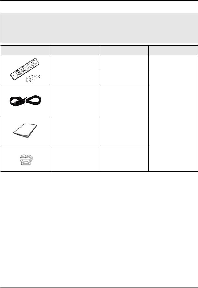
2-3. Accessories
 NOTE
NOTE
•The items’ colors and shapes may vary depending on the model.
•Cables not included in the package contents can be purchased separately.
•The part code for some accessories may differ depending on your region.
Product |
Description |
Code. No |
Remark |
|
Remote Control & |
BN59-01223A |
|
|
|
|
|
|
Batteries |
|
|
|
(AAA x 2) |
4301-000103 |
|
|
|
|
|
|
Power Cord |
3903-000853 |
|
|
|
|
- |
|
Manual Users |
BN68-06969A |
|
|
Holder-Wire Stand |
BN61-08370A |
|
2-8

3. Disassembly and Reassemble
3. Disassembly and Reassembly
This section of the service manual describes the disassembly and reassembly procedures for the LED TV.
This LED TV contains electrostatically sensitive devices. Use caution when handling these components.
WARNING
3-1. Disassembly and Reassembly
1.Disconnect the LED TV from the power source before disassembly.
2.Follow these directions carefully; never use metal instruments to pry apart the cabinet.
CAUTION 3. If there is no additional coment, it is same for all inches.
Description |
Picture Description |
Screws |
1 Place TV face down on cushioned table.
Remove Screws from the ASSY GUIDE |
Torque : |
|
2 P-STAND and Remove ASSY GUIDE |
||
9~ 10Kgf.cm |
||
P-STAND. |
|
•32" : 3 EA
• 40"/48"/50"/55" : 4 EA
6003-001782
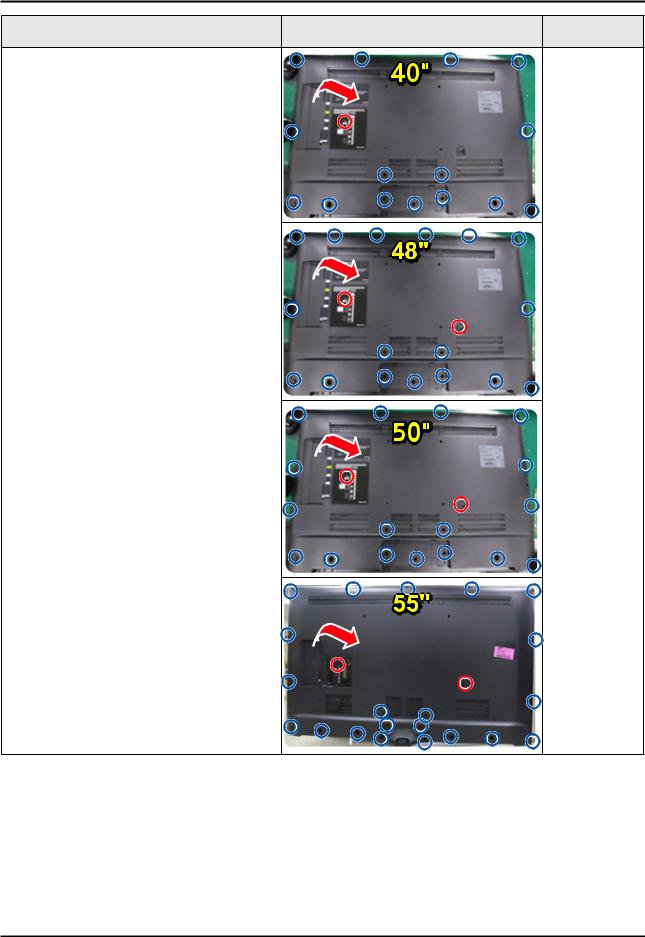
Remove Screws of ASSY COVER |
Torque : |
|
3 P-REAR. |
||
9~ 10Kgf.cm |
||
• 32" : 12 EA |
|
6003-001782
Torque : 7~ 8Kgf.cm
6003-002755
3-1
3. Disassembly and Reassemble
Description |
Picture Description |
Screws |
• 40" : 16 EA
• 48" : 18 EA
• 50" : 20 EA
• 55" : 23 EA (ONLY MEXICO)
3-2
|
|
|
3. Disassembly and Reassemble |
|
|
Description |
Picture Description |
Screws |
|
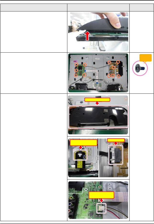
4 |
Remove the ASSY COVER P-REAR. |
|
|
|
5 |
Remove 10 Screws of ASSY PCB MAIN |
|
|
Torque : |
and DC VSS-LED TV PD BD. |
|
|
||
|
|
7~ 8Kgf.cm |
||
|
|
|
|
6001-002756 |
6 |
Remove the ASSY SPEAKER P (R/L) and |
|
|
|
Power Cables. |
ASSY SPEAKER P |
|
||
|
|
ASSY BOARD P-BT |
Power Cable |
|
|
|
MODULE Cable |
|
|
|
|
ASSY SPEAKER P |
|
|
|
|
|
Cable |
|
|
|
|
|
3-3 |
3. Disassembly and Reassemble |
|
|
|
|
Description |
Picture Description |
Screws |
7 |
Cable.Remove the LVDS Cable and Panel Drive |
LDVS Cable |
|
|
|
|
|
|
|
Panel Drive Cable |
|
8 |
ASSY.Remove the ASSY BOARD P-FUNCTION |
|
|
|
|
ASSY BOARD |
|
|
|
P-FUNCTION |
|
|
|
ASSY |
|
|
|
Cable |
|
|
|
NETWORK-WIFI |
|
|
|
MODULE |
|
|
|
Cable |
|
9 |
Completed disassembly. |
|
|
 NOTE
NOTE
Reassembly procedures are in the reverse order of disassembly procedures.
3-4
4. Troubleshooting
4. Troubleshooting
4-1. Troubleshooting
Previous Check
1.Check the various cable connections first.
-- Check to see if there is a burnt or damaged cable.
-- Check to see if there is a disconnected or loose cable connection.
-- Check to see if the cables are connected according to the connection diagram.
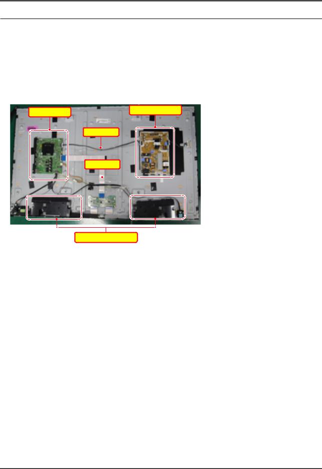
2.Check the power input to the ASSY PCB MAIN.
ASSY PCB MAIN |
DC VSS-LED PD BD |
|
Power Cable
LVDS Cable
Cable
ASSY SPEAKER P (R/L)
3. Check the power in & output between DC VSS-LED PD BD & ASSY PCB MAIN, ASSY PCB MAIN & Panel, IP & Panel.
4-1

4. Troubleshooting
4-2. How to Check Fault Symptom
4-2-1. Video
MAIN / FRC / T-CON
Major check points
CHECK TEST PATTERNS
1Verify "Scaler Pattern".
2Verify "US Post Pattern".
3Also : Check "Mute 147 Mute Pattern".
There are No Test patterns for T-CON Board since there is no FRC Circuit. In this model.
•ENTER : Factory mode  SVC
SVC  Info
Info  Test Pattern
|
|
1 Scaler Pattern |
|
|
|
|
|
|
|
|
Main Board |
|
T-CON BOARD |
|
|
|
|||
|
|
|
|
|
|
HAWK-MF |
LVDS |
T-CON |
|
|
|
|
|
(NO FRC) |
2 US Post Pattern
4-2

4. Troubleshooting
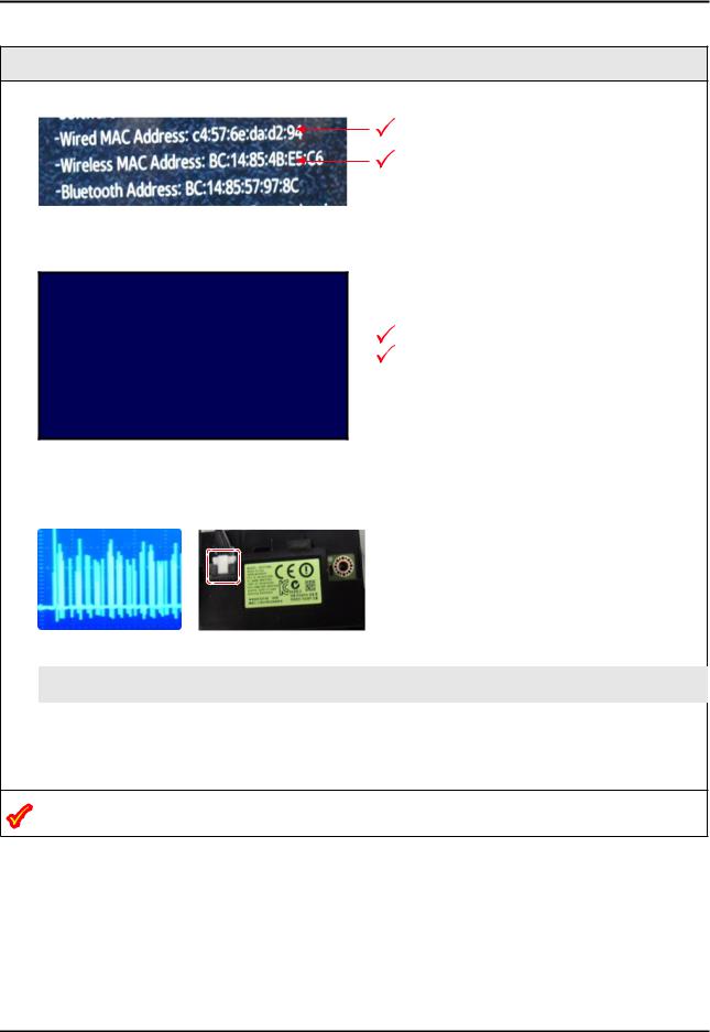
4-2-2. Bluetooth / WIFI Module
Bluetooth Module
Major check points
1. Check Bluetooth Address at Contact Samsung.
BT Address
2.Check BT F/W Version at Factory Mode screen.
-- Might require upgrade. Check GSPN.
T-HKPAKUC-XXXX.XX
T-HKPAKUS-XXXX
tztv-X.X 1-XXXX-X_2015XXXX.X (XXXX)
BT Version : BLUETOOTH-VER-XXXX |
BT Version |
E-Manual : X.XXX |
|
Camera Version : X.XX.XX |
|
Blaster Bersion : XXXXXX-XXXXXX-XXXXXX |
|
. |
|
. |
|
. |
|
3.If errors exist than Check BT Connector Voltages. If DC voltages are missing check cable & Main Board feed. -- If DC voltages are missing check cable & Main Board feed.
BT Signal
(4V P-P)
Pins |
1 |
2 |
3 |
4 |
5 |
6 |
7 |
8 |
9 |
10 |
|
|
|
|
|
|
|
|
|
|
|
|
|
Standby |
0 |
3.3 |
0 |
0 |
0 |
0 |
0 |
3.3 |
0 |
3.3 |
|
Vdc |
Vdc |
Vdc |
|||||||||
|
|
|
|
|
|
|
|
||||
Power ON |
3.3 |
3.3 |
|
|
2V |
1V |
|
3.3 |
3.3 |
3.3 |
|
0 |
0 |
BT Sig. |
BT Sig. |
0 |
|||||||
Vdc |
Vdc |
Vdc |
Vdc |
Vdc |
|||||||
|
|
|
4V P-P |
4V P-P |
|
||||||
|
|
|
|
|
|
|
|
|
•All Measurements in the Chart are DC Volts with Multi Meter.
•Bluetooth Sig. & Sync Pulse are effective DC Readings.
4.If voltages OK but BT Sig. pins (DC Ref.) Voltages are missing, The BT Module is likely defective.
Voltage is normal, but BT Sig. pins (DC Ref.) If you do not measure, BT Module can possibly defective.
4-3
4. Troubleshooting
WIFI Module
Major check points
1. Check Wired MAC Address and Wireless MAC Address at Contact Samsung.
Wired MAC Address
Wireless MAC Address
2.Check Wired MAC and Wireless MAC at Factory Mode screen. (Success/Failure)
-- Wired MAC errors : Main Board is defective.
.
.
Model : UNXXJSXXXX
Wired MAC SUCCESS 
Wireless MAC SUCCESS 
WIFI Version : ****
.
.
-- Wireless MAC errors :
•Check the Wi-Fi Module Connector voltage. -- If OK replace Module.
Wired (SUCCESS)
Wireless (SUCCESS)
Wi-Fi Signal
(500mv P-P)
Pins |
1 |
2 |
3 |
4 |
5 |
6 |
|
|
|
|
|
|
|
|
|
Standby |
0 |
0 |
0 |
0 |
.8 |
0 |
|
|
|
|
|
|
|
|
|
Power ON |
0 |
.04Vdc Wi-Fi |
.04Vdc Wi-Fi |
5.3 Vdc |
3.3 Vdc |
3.3 Vdc |
|
Sig |
Sig |
||||||
|
|
|
|
|
•All Measurements in the Chart are DC Volts with Multi Meter.
Voltage is normal, but Wi-Fi Sig. pins (DC Ref.) If you do not measure, Wi-Fi Module can possibly defective.
4-4

4. Troubleshooting
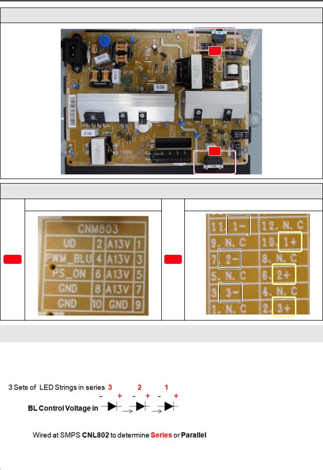
4-2-3. SMPS
SMPS Power On Sequence
A
B
Detail
To Main Board CNM803 |
To Panel LEDS CNL802 |
A |
B |
 NOTE
NOTE
A13V for Standby & Operation (no longer A5V & no “B” voltages)
Testing
1A13V Standby to Main Board: varying from 7.5~12.7 Vdc
2PS_ON : 3.3Vdc Power ON/OF
3A13V : to steady 12.7 Vdc
4UD ( Under Drive) : 3.3Vdc also labeled “OD/UD”
5BLU_PWM: .9V~3.3Vdc also labeled “BLU On/Off” Backlight On/Off & Backlight (PWM signal) Level Control.
4-5
4. Troubleshooting
SMPS : Backlight
A
B
Detail
To Main Board CNM803 |
Drive To Panel LEDS (CNL802) |
A |
B |
Example of Models with Series Strings of LEDs (size related) If one LED string goes out all are out, no backlight.
|
|
|
|
|
|
|
|
|
|
|
|
|
|
|
|
|
|
|
|
|
|
|
CNL802 (to BLU) |
|
|
||
|
|
|
|
|
|
|
|
|
|
|
|
|
|
|
|
|
|
|
|
|
|
1 |
NC |
9 |
|
NC |
|
|
|
|
|
|
|
|
|
|
|
|
|
|
|
|
|
|
|
|
|
|
|
2 |
3+ |
10 |
|
1+ |
|
|
3 Sets of LED Strings in series |
|
|
|
|
|
|
|
|||||
|
|
|
|
|
|
|
|
|
|
|
|
||
|
|
|
3 |
3- |
11 |
|
1- |
|
|||||
|
|
|
|
|
|
|
|
|
|
||||
|
|
|
|
|
|
|
|
|
|
||||
|
|
|
|
|
|
|
|
|
|
|
|
|
|
|
|
|
|
|
Fixed |
|
4 |
NC |
12 |
|
NC |
|
|
|
|
BL Control Voltage in |
|
|
|
|
|||||||
|
|
|
|
Supply |
|
|
|
|
|
|
|
||
|
|
|
|
|
|
5 |
NC |
13 |
|
NC |
|
||
|
|
|
|
|
|
|
|
|
|
||||
|
|
|
|
|
|
|
|
|
|
|
|
|
|
|
|
|
|
|
|
|
|
6 |
2+ |
14 |
|
NC |
|
|
|
Wired at SMPS CNL802 to determine Series or Parallel |
|
|
|
|
|
||||||
|
|
|
|
|
|
|
|
|
|
|
|||
|
|
|
7 |
2- |
15 |
|
IF2 |
|
|||||
|
|
|
|
|
|
|
|
|
|
||||
|
|
|
|
|
|
|
|
|
|
||||
|
|
|
|
|
|
|
|
|
|
|
|
|
|
|
|
|
|
|
|
|
|
8 |
NC |
16 |
|
IF1 |
|
|
|
|
|
|
|
|
|
|
|
|
|
|
|
|
|
|
|
|
|
|
|
|
|
|
|
|
|
|
|
|
|
|
|
|
|
|
|
|
|
|
|
4-6
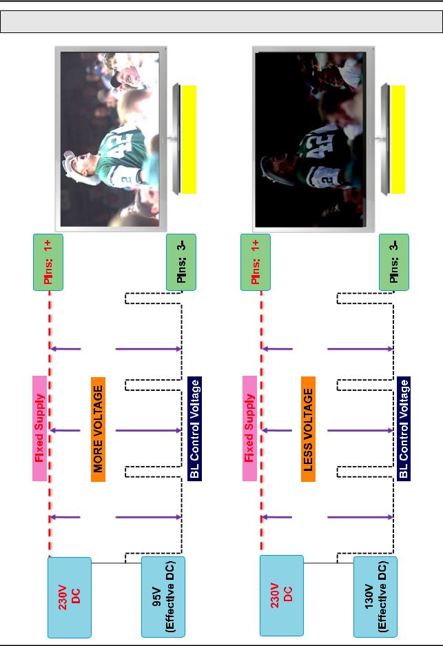
4. Troubleshooting
Back Light Operation: LED Drive
4-7
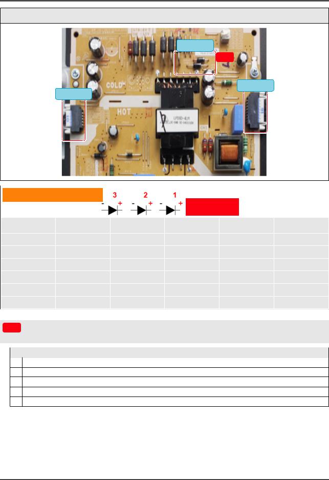
4. Troubleshooting
SMPS / Backlight Test
230Vdc
A
CNL802
CM803
3 LED Strings Control
|
|
|
|
|
Fixed Supply |
|
|
|
|
LED Pins |
Min B/L |
Max B/L |
Full B/L Test |
Panel Con. |
Sample |
|
|
Removed |
2- open |
||||
|
|
|
|
|
|
||
|
|
3- |
130Vdc |
95Vdc |
88Vdc |
0 |
0 |
|
|
3+ |
174Vdc |
151Vdc |
144Vdc |
0 |
0 |
|
|
2- |
174Vdc |
151Vdc |
144Vdc |
0 |
Opened |
|
|
2+ |
218Vdc |
207Vdc |
200Vdc |
0 |
257Vdc |
|
|
1- |
218Vdc |
207Vdc |
200Vdc |
0 |
257Vdc |
|
|
1+ |
241Vdc |
235Vdc |
230Vdc |
275Vdc |
279Vdc |
|
|
|
|
|
|
|
|
|
A |
230Vdc (panel size dependent) BL Supply measured at diode Stripe(cathode). This will raise to approx 280Vdc |
|||||
|
|
||||||
with an open string of LEDs. |
|
|
|
|
|||
|
|
|
|
|
|
|
|
|
|
|
|
Simplified BACKLIGHTS Test |
|
|
|
|
|
1 Activate Backlights – Disconnect |
Lead Cable from Main to Power Supply. |
|
|||
2Measure BL Supply voltage at 1+ or at the supply diode cathode (stripe).
3Remove Panel connector and measure again to compare.
4If voltage is high and stays the same high reading a string of Panel LEDs are open. Replace the Panel.
If the voltage is low and remains low the SMPS is defective.
4-8
4. Troubleshooting
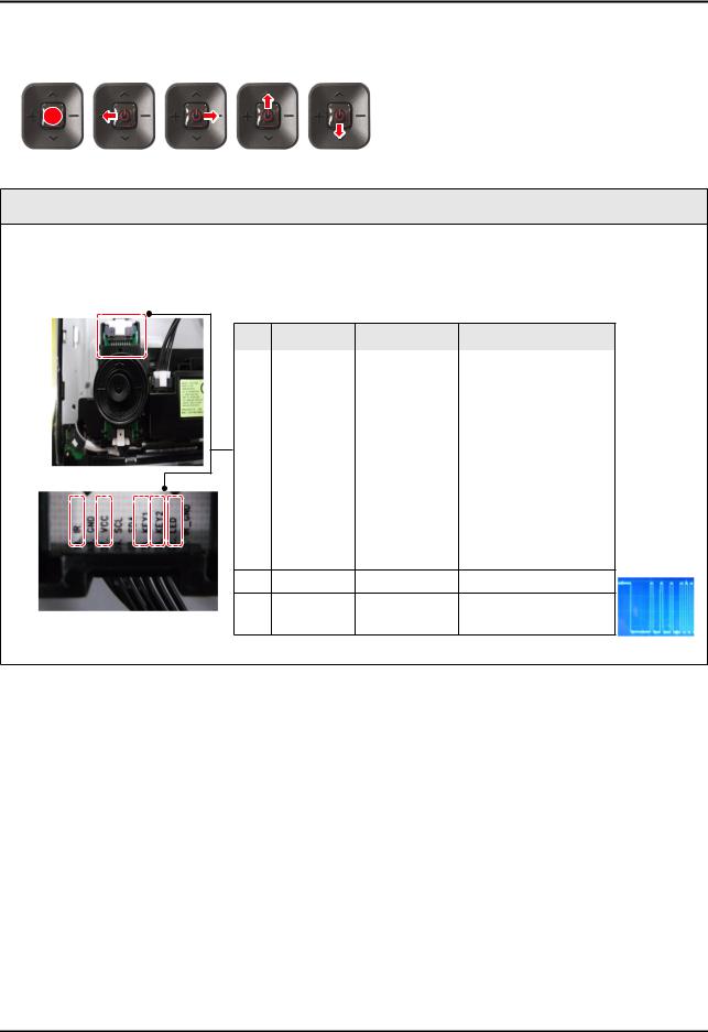
4-2-4. Jog Function Control
Jog Function Control Operation
Press |
Left |
Right |
Up |
Down |
Major check points
1.Check Jog Shuttle STBY Voltages (All at 3.3 V except LED).
2.Check Jog Shuttle 5 SW Operation (Key 1 & Key 2) for each command change.
3.Check LED Indicator for STBY operation. (Check 1.8 V Supply from Main Board.)
Pin |
Action |
Signal |
|
DC Voltage |
|
|
|
|
|
1 |
IR Gnd |
|
No connection |
|
|
|
|
|
|
2 |
|
LED |
1.8V |
( in STBY) |
|
|
|
|
|
3 |
left |
Key 2 |
3.3V |
DC to 1.6V DC |
3 |
Right |
Key 2 |
3.3V |
DC to 2.5V DC |
3 |
Up |
Key 2 |
3.3V |
DC to 0.0V DC |
3 |
Down |
Key 2 |
3.3V |
DC to 0.8V DC |
4 |
Press |
Key 1 |
3.3V |
DC to 0.0V DC |
5 |
|
SDA |
3.3V |
|
6 |
|
SCL |
3.3V |
|
7 |
|
STBY |
3.3V |
|
8GND
9 |
IR |
IR |
3.3V to 2.5V DC |
|
|
|
With Commands |
4-9
Loading...