Type of protection against electrical shock: Class I
- Degree of protection against electrical shock (Patient connection):Type BF equipment
Degree of protection against harmful ingress of water: Ordinary equipment
Degree of safety of application in the presence of a flammable anesthetic material with air
or with oxygen or nitrous oxide: Equipment not suitable for use in the presence of a
flammable anesthetic mixture with air or with oxygen or nitrous oxide.
Mode of operation: Continuous operation
Electromechanical safety standards met:
- IEC/EN 60601-1 Medical Electrical Equipment, Part 1General Requirements for Safety.
- IEC/EN 60601-1-1 Safety requirements for medical electrical systems.
- IEC/EN 60601-1-2 Electromagnetic compatibility -Requirements and tests.
- IEC/EN 60601-2-37 Particular requirements for the safety of ultrasonic medical diagnostic
and monitoring equipment.
- IEC 61157 Declaration of acoustic output parameters.
- ISO 10993-1 Biological evaluation of medical devices.
- UL 60601-1 Medical Electrical Equipment, Part 1 General Requirements for Safety.
- CSA 22.2, 601.1 Medical Electrical Equipment, Part 1 General Requirements for Safety.
Page 4
Declarations:
This is the CSA symbol for Canada and United States of
America
0123
This is the manufacturer’s declaration of product
compliance with applicable EEC directive(s) and the
European notified body.
This is the manufacturer’s declaration of product
compliance with applicable EEC directive(s).
This is the GMP symbol that shows that the product
complies with the Korean Good Manufacturing Practice
quality regulation system.
Page 5
DANGER
Disregarding this instruction may result in death, serious injury, or other
dangerous situations.
WARNING
Follow this information to prevent a serious accident or damage to property.
CAUTION
Hazards or unsafe practices that may result in minor personal injury or property
damage.
NOTE
The accompanying information covers an installation, operation, or maintenance
procedure that requires careful attention from the user, but has little chance of leading
directly to a dangerous situation.
Attention
Read this service manual to familiarize yourself thoroughly with repair procedures and important safety
information before attempting to service the product.
Failure to follow this information may cause an accident such as electric shock, as well as mechanical
or other hazards to the service engineer, product operator, and/or patient.
1) Refer to the service manual when you service the product.
2) You are strongly urged to familiarize yourself with the operational safety information contained in
‘Chapter 2 Safety’.
3) This product is an ultrasound diagnosis device and cannot be used from the user's PC.
We are not responsible for errors that occur when the system is run on the user’s PC.
4) This product may only be serviced by the Global Service Team of Samsung Medison or an
authorized engineer.
5) Samsung Medison is not responsible for any problems caused by an unauthorized person
servicing the product.
6) The manufacturer is not responsible for any damage to this product caused by user carelessness
and/or neglect.
7) The content of this manual may be changed without prior notice.
8) The following terms are used to highlight safety precautions that the user must be aware of:
Page 6
If You Need Help
If you need help regarding the product, please contact the Samsung Medison Global Service Team in
charge of servicing this product.
Page 7
UGEO H60 Service Manual
Table of Contents
Chapter 1 Introduction to Products ....................................................................1-1
Chapter 1 describes the basic important information you need to know before
repairing UGEO H60. It describes the main features and configuration and the
product specification.
UGEO H60, a color ultrasound diagnostor with high resolution and deep
penetration, is convenient and offers variety of measurement functions
Digital Beam forming technology, self-developed at Samsung Medison Co., Ltd.
Is applied.
Various Application: Can be applied to various fields such as General, Obstetrics,
Gynecology, Abdomen, Vascular, Extremity, Cardiac, Urology, Breast
Various Diagnostic Modes: Various types of modes are available such as 2D mode, M mode,
Color Doppler Mode (C mode), Power Doppler Mode (PD mode), PW Spectral Doppler
Mode (D mo de)
Stereoscopic Feature: Implements solid and detailed visuals with 3D and 4D imaging mode.
Measuring and Reporting Feature: Offers various measurement functions for each specific
area besides measurement functions for distance, area, volume and perimeter. In addition,
there is a report function using this measurement result.
Reviewing Scan Video Feature: Provides 2621 frames of Cine video and 4086 lines of
Loop video at maximum.
SonoViewTM Feature: Available on storing, querying and compatible data with integrated
video management system.
Digital Imaging and Communication in Medicine (DICOM) Feature: Can store, transfer, and
print video using network.
Ease of Connection to Peripheral Devices: Can connect to various peripheral devices and
use it.
Chapter 1 Introduction to Products 1-2
Page 16
UGEO H60 Service Manual
1.3 Components
UGEO H60 is composed of console, probe and cart (option).
1.3.1 Console
The internal part of console is composed of devices mainly implementing
ultrasound image, while the external part is composed of various connected
devices and handle.
[Figure 1-1] H60 Front Figure
[Figure 1-2] H60 Side Figure
Chapter 1 Introduction to Products 1-3
Page 17
NOTE
Refer to "Chapter 9 Probe" in service manual for more detail.
1.3.2 Probe
Probe is a device collecting data for ultrasound image by using ultrasound.
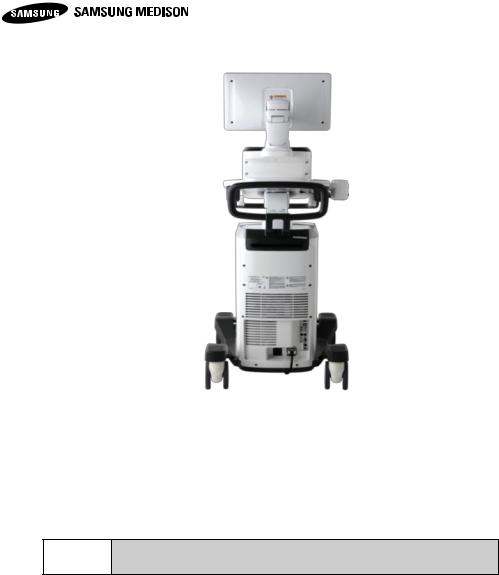
[Figure 1-3] H60 Rear Figure
Chapter 1 Introduction to Products 1-4
Page 18
UGEO H60 Service Manual
1.3.3 Product Specification
Physical Dimensions
Height: 1660 mm (with Monitor)
Width: 550 mm
Depth: 980 mm(with Keyboard)
Weight: 105kg (without accessories)
Transmit focusing, maximum of eight points (four points
simultaneously selectable)
Digital dynamic receive focusing (continuous)
Probes
(Type BF / IPX7)
Linear Array
L5-13
Curved Array
CS1-4, C2-8, CF4-9, ER4-9,EVN4-9
3D
3D2-6, 3D4-9, VE4-8
Probe connections
3 Probe Connectors
4 Probe Connectors for option
Monitor
Main Monitor
Display area : 18.5 inch
Number of Pixel : 1366 x 768
Touch Screen Monitor
Display area : 10.1 inch
Number of Pixel : 1280 x 800
Chapter 1 Introduction to Products 1-5
Page 19
Rear Panel
Input / Output
Connections
Audio Output Port( Right/Left )
VGA monitor
LAN
USB Port
HDMI output
HDMI Input (HDMI Input is currently not supported.)
Image Storage
Maximum 45000 frames for CINE memory
Maximum 14000 Lines for LOOP memory
Image filing system
Application
Obstetrics, Gynecology, Urology, Abdomen, Vascular,
Small Part, MSK Pediatric
Electrical Parameters
100~240VAC, 620VA, 50/60Hz
Measurement
Packages
Abdomen, Obstetrics, Fetal Echo, Gynecology, MSK,
Pediatric Hips, Small Part, Urology, Vascular
* Refer the Chapter 5 for additional information
Signal processing
(Pre-processing)
Acoustic Power Control
Analog TGC Control
Dynamic Aperture Control
Dynamic Apodization Control
Dynamic LPF Control
Signal processing
(Post-processing)
Digital TGC Control
Slider TGC Control
Mode-Independent Gain Control
Black Hole/Noise Spike Filtering
1D Lateral/Axial Filtering
2D Edge/Blurring Filtering
Frame average
M/D Mode Sweep Speed Control
Zoom
Image View Area Control
Image Orientation (left/right and up/down)
Chapter 1 Introduction to Products 1-6
Page 20
UGEO H60 Service Manual
Measurement
Trackball operation of multiple cursors
2D mode: Linear measurements and area measurements
using elliptical approximation or trace
M mode: Continuous readout of distance, time, and slope
rate
Doppler mode: Velocity and trace
Auxiliary
DVD Multi-Drive
Digital B/W Video Printer
Digital Color Video Printer
USB Printer
DVD Recorder
Foot switch (IPX8)
e-Motion Marker (IPX 7)
USB Flash Memory Media
USB HDD
Monitor
User Interface
English, German, French, Spanish, Italian, Russian,
Chinese
Pressure Limits
Operating: 700hPa to 1060hPa
Storage: 700hPa to 1060hPa
Humidity Limits
Operating: 30% to 75%
Storage & Shipping: 20% to 90%
① Monitor
② Monitor Arm
③ Keyboard
④ Control Panel
⑤ Lift
⑥ Probe Holder
⑦ DVD Drive
⑧ USB Port
⑨ Speaker
⑩ Probe Port
⑪ Wheel
1.3.4 Product Components
This product is composed of monitor, control panel, console, peripheral devices
and probe.
Chapter 1 Introduction to Products 1-8
1.3.4.1 Monitor
Color LCD flat monitors displays ultrasound image and extra information.
1) Screen Configuration
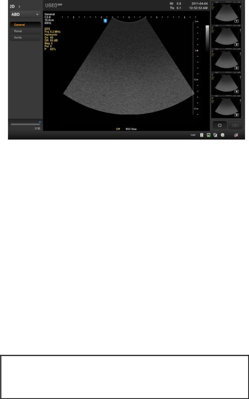
The screen of this product has contents such as ultrasound image and extra
information, and necessary menu for users to operate the system. The screen
configuration is composed of ①Title area, ②Measurement menu area, ③
Imaging area, ④ Thumbnail area, ⑤User Information as the figure below.
[Figure 1-4] The front of the product
Page 22
UGEO H60 Service Manual
① Title area
※Tips! Displays of current condition of system.
: Shows On condition of Caps Lock
: Shows that there is CD/DVD storage media
①
②
③
④
⑤
[Figure1-5] Screen Configuration
Displays patient information (name, ID, GA), name of hospital and operator,
acoustic output information, date and time, etc.
② Measurement menu area
Displays measurement menu while measuring each subject diagnosis.
③ Imaging area
Displays ultrasound image. Displays video information, annotation and various
measuring information.
④ Thumbnail area
Displays stored video by clicking [Store] button. Clicking by pointer will display
enlarge image on imaging area. Display up to 17 images.
Displays Body Marker in BodyMarker Mode.
⑤ User Information Status Information area
Displays various information needed for users while operating this system.
Displays condition of the storage media (HDD, USB, CD), Caps Lock condition,
DICOM, etc.
Chapter 1 Introduction to Products 1-9
Page 23
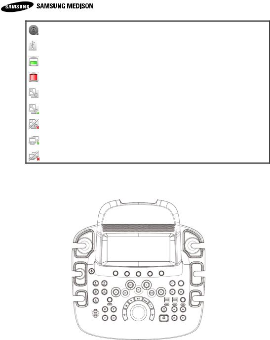
: Shows that there is no CD/DVD storage media.
: Shows that there is no USB storage media.
: Shows that there is more than 10% of HDD storage.
: Shows that there is less than 10% of HDD storage.
: Shows that DICOM Spooler is empty.
: Shows that DICOM Spooler is in operation.
: Shows that DICOM Spooler has failed in its operation.
: Shows that LAN is connected.
: Shows that LAN is not connected.
1.3.4.2 Control Panel
Users operate the system with control panel.
Control panel is composed of keyboard, soft menu, button, dial, dial-button, slide
and track.
Dial-button is a operating tool, combination of dial and button.
[Figure 1-6] Control Panel
Chapter 1 Introduction to Products 1-10
Page 24
UGEO H60 Service Manual
On/Off
Button
Turns On/Off the product
Patient
Button
Displays Patient Information screen where you can select
the patient ID on the list or input new patient information
Probe
Button
Displays Probe Selection screen where you can select and
change the probe and diagnostic subject
SonoView
Button
Displays a screen where you can review or manage stored images
End Exam
Button
Reset the related data after finishing the examination on
the diagnosed patients
Report
Button
Displays the report screen which shows measurement
result of corresponding diagnostic subject
Button
Inputs BodyMarker on the video
Button
Inputs texts on the video
U1
Button
This button can be set to user's preference. Features of
each button can be set from Setup > Peripherals >
Customize Key
U2
Button
This button can be set to user's preference. Features of
each button can be set from Setup > Peripherals >
Customize Key
Button
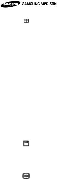
Displays exclusive videos on the screen
Button
Compares two separate videos
1) Detailed Features of Control Panel
Following are the description and the use of each control on control panel.
Controls with various different features are described in more detail after Chapter
3 of this manual.
Chapter 1 Introduction to Products 1-11
Page 25
Button
Compare four separate videos
Depth
Dial-Button
Adjusts the depth of the image which can be observed
Focus
Dial-Button
Moves the position of the focus to the desired target area
Zoom
Dial-Button
Zoom Box appears.
Press [Exit] button to exit Zoom mode.
Angle
Dial-Button
Adjusts the angle of sample volume in spectral doppler
mode. Also used for adjusting the angle of arrow and
adjusting probe angle of Body marker.
Moves Reference Slice to the left and right using [Angle]
Dial-Button in 3D View
Q Scan
Button
Uses Quick Scan feature
Store,
S1, S2,
S3
Button
Stores, prints and sends to DICOM Server with having
settings of each feature for each.
Features of each Button can be set from Setup >
Peripherals > Customize Keys
Freeze
Button
Stops the video which is being scanned or reactivates the
stopped video
M
Dial-Button
Starts or exits the M mode. Adjusts gain by turning DialButton. Rotates the image in the direction of the x-axis in
3D View
PD
Button
Starts or exits power doppler mode
Color
Dial-Button
Starts or exits color doppler mode. Adjusts gain by turning
Dial-Button.
Rotates the image in the direction of the x-axis in 3D View
2D
Dial-Button
Starts 2D mode. Adjusts gain by turning Dial-Button.
Chapter 1 Introduction to Products 1-12
Page 26
UGEO H60 Service Manual
PW
Dial-Button
Starts or exits PW spectral doppler mode. Adjusts gain by
turning Dial-Button.
Rotates the image in the direction of the y-axis in 3D View
CW
Button
This button is currently not supported
3D / 4D
Button
Used for On / Off on 3D/4D mode.
Set / Exit
Button
[Uses by setting the [Set] or [Exit] feature. Features of each
Button can be set from Setup > Peripherals > Customize
Keys
- Set: Selects desireditem or value using trackball, or
changes the feature of trackball.
- Exit: Exists the current feature and returns to the previous
state
Pointer
Button
The arrow pointer appears on the screen in the scan mode
Clear
Button
Deletes text, arrow, body marker, measurement result, etc
displayed on the screen
Change
Button
Changes to other feature which is supported in the current
trackball feature
Calculator
Button
Starts measuring on each diagnostic subject
Caliper
Button
Starts basic measurement such as distance, volume,
circumference and area
Trackball
Trackball
Moves the cursor on the screen. There are video search
feature in Cine footage.
CAUTION
Bands might appear on the image if adjusting gain value of
adjacent TGC slide with large difference
Chapter 1 Introduction to Products 1-13
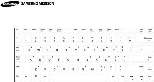
Page 27
2) Keybard
Help
Help Manual appears on the screen
Patient
General Information appears on the screen
Patient info.
Shows or hides patient information on the screen
Image Info.
Shows or hides Image Parameter on the screen
DICOM Spooler
DICOM Spooler appears on the screen
Arrow
Starts Arrow mode
Home
Moves cursor to the Home position in Annotation mode
Set Home
Sets the Home position in Annotation mode
Delete Word
Deletes last inputted text in Annotation mode
Used to input texts
[Figure 1-7] Keyboard
Chapter 1 Introduction to Products 1-14
Page 28
UGEO H60 Service Manual
Delete All
Deletes all inputted text in Annotation mode
Setup
Setup screen appears
Insert
Select the input method
Decrease the brightness of the monitor by pressing the Fn key
Delete
Deletes Text
Increase the brightness of the monitor by pressing the Fn key
3) Touch-Screen
It is an operating tool which users directly touch. The available features are shown
as Button or Dial Button in the current mode.
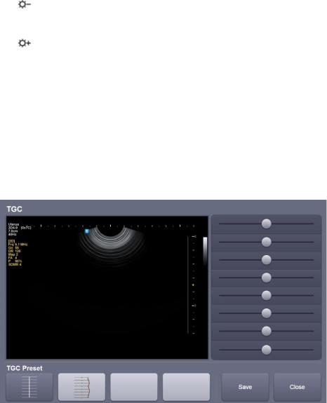
Screen configuration of touch-screen
① Information area: shows the title of touch screen currently used.
② TGC: adjusts TGC slide when TGC curve settings on the touch screen is active.
[Figure 1-8] TGC
③ Menu area: The available menu in the current input mode is shown as Button.
Use by pressing the Button itself, and menus which are being used are shown
as yellow.
Chapter 1 Introduction to Products 1-15
Page 29
※ Tip! When there are two menu for touch screen
In case there are 2 menus on the top and bottom, press corresponding DialButton and select the desired menu. Use Dial-Button after pressing the Button
on the menu that you wish to use on the touch screen.
CAUTION
Do not move the control panel with excessive force.
Use the rear handle to move the product
①
②
③
④
④ 
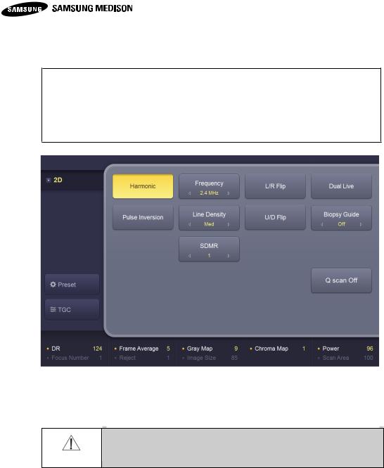
Soft menu area: shows soft menu available in current input mode. Use by
pressing Dial-Button right below the menu or turning it to left or right.
[Figure 1-9] Display of touch-screen
4) Adjustment of the Control Panel
① Horizontal Adjustment
Move the product carefully side to side by holding the handle.
② Vertical Adjustment
Move the product carefully up and down by pressing the lever on the handle of
control panel.
Chapter 1 Introduction to Products 1-16
Page 30
UGEO H60 Service Manual
① HDMI: delivers digital type image and audio
signals in one cable simultaneously
② USB port: connects peripheral devices for
USB
③ Audio Output (input): is used for output of
audio signal
④ S-VHS port (I/O): connects VCR in S-VHS
method
⑤ D-SUB port: outputs analog signals to
monitor
⑥ Network port: connects network
⑦ Mic port (input): connects microphone
[Figure 1-10] Rear panel
①
②
③
⑤
④
⑥
⑦
1.3.4.3 Console
Console is divided into two main parts of the internal and external. The internal of
the console is consisted of the devices for implementing ultrasound image. The
external of the console is composed of various connected devices, probe holder,
storage space, handle, wheel, etc.
1) Rear Panel
Located on the back of the product, it connects various peripheral devices such
as monitor, printer, etc..
2) Power connector
Chapter 1 Introduction to Products 1-17
Page 31
NOTE
Refer to the user's manual of corresponding product for the use of
peripheral device.
CAUTION
Do not install peripheral devices not mentioned in this manual
to the patient environment. There is a risk of electric shock
when you install peripheral devices in the patient environment.
Located at the bottom of the rear panel
[Figure 1-11] Power connector
① Power Inlet: a connected part of power cord connecting external power source
② Power Outlet: supplies power for peripheral devices or external devices, and
capacity is MAX150VA. Outlet terminal is located on DC power assy.
③ Power switch / circuit breaker: supplies power for the entire product or cut the
power supply in case of overvoltage or overcurrent.
3) Probe Holder
Holder is located on the left and right of the control panel for storing Probe.
1.3.4.4 Peripheral Devices
1) Internal peripheral devices
These are the peripheral devices located inside of the console.
Connect it upon the user's need. The connection is usually made through the
corresponding port on the rear panel.
Chapter 1 Introduction to Products 1-18
Page 32
UGEO H60 Service Manual
※ Tip!
USB port of the console is located on both side panel and rear panel of the
control panel.
It is convenient to connect USB storage devices (flash memory media, etc) on
the side panel of the port, and other USB peripheral devices on the rear panel.
CAUTION
For peripheral devices using USB port, make sure you turn the
power off before equipping or removing the device to the
console. Malfunction of peripheral devices for system or USB
can be occurred when the power is not completely off.
[Figure 1-12] Patient Environment
The following products are recommended.
Digital Video Printer
- BW: Sony UP-D897, Mitsubishi P95DE
- Color: Sony UP-D25MD, Mitsubishi CP30DW
USB Printer
HP Officejet 4500, Samsung ML-2950ND, Samsung CLP-620NDK
DVD Recorder
Sony DVO-1000MD
Chapter 1 Introduction to Products 1-19
Page 33
CAUTION
■ Must install printer and driver compatible with English
Microsoft Windows XPTM. Contact Samsung Medison
customer service for details of installing printer driver.
■ Check to make sure the printer is same as the one in
Windows XPTM or Setup, when connecting to the printer.
■ Please note that the connecting port is different depending
on the printer. General printer is connected to the printer
port while USB printer to the USB port.
NOTE
Refer to ‘Chapter 5 Probe’ for more detail.
Foot Switch
Foot Switch feature can be enabled on Setup > Peripherals > Customize Keys >
Foot Switch. You can choose options from Exit, Freeze, Store, S1, S2, S3 and
Update.
1.3.4.5 Probe
Probe is a device collecting data for the ultrasound imaging configuration using
ultrasound.
1) How to connect the probe
Turn the power off before equipping or removing probe from probe connector for
the safety of product and probe.
① Connect probe to the probe connector on the front panel of the console. It can
connect up to maximum of 4 probes (including option).
② Equip it by turning the handle of the connector clockwise.
Chapter 1 Introduction to Products 1-20
Page 34
UGEO H60 Service Manual
[Figure 1-13] Probe connectors
1.3.4.6 Accessory
This product includes a box containing various accessories.
[Figure 1-14] Accessories
Chapter 1 Introduction to Products 1-21
Page 35
SDMR
Spatial Compound Imaging™ (SCI™)
DICOM
4D
3D XI
Volume NT / IT
Refer to the corresponding content of this manual for more details of options
above.
Chapter 1 Introduction to Products 1-22
Page 36
2.1 Overview
Safety
2
2.2 Safety Precautions
2.3 Electrical Safety
2.4 Mechanical Safety
2.5 Biological Safety
2.6 Protecting Environment
Page 37
UGEO H60 Service Manual
2
Safety
2.1 Overview
Chapter 2 describes the important considerations for safely repairing UGEO H60.
There are details of other additional equipment such as ultrasound system, probe,
recording device.
This product should only be used by the qualified doctors who are authorized to
use medical devices or the persons who are authorized by doctors.
It can adversely affect the fetus if unqualified medical personnel or regular
personnel use the solid ultrasound (3D, 4D) for a long period for taking
commemorative photos or video.
In case of solid ultrasound imaging device, please comply with the intended use
because it can adversely affect the fetus when taking videos for other than the
purpose of prenatal diagnosis.
Classification according to the degree of protection
against electrical hazards (Type BF)
Classification according to the degree of protection
against electrical hazards (Type CF)
Power switch (supplies/cuts off the power)
OFF (cuts off the power on parts of the product)
Warning: to prevent serious accidents or property damage
Caution: to prevent minor accidents or property damage
Refer to the user's manual
ON (supply the power on parts of the product)
Equipotential terminal
2.2 Safety Precautions
2.2.1 Safety Symbols
IEC (International Electrotechnical Commission) has enacted safety and safety
symbols for medical electronic devices. Enacted symbols are as following.
Chapter 2 Safety 2-2
Page 39
UGEO H60 Service Manual
Symbol
Meaning
High-voltage beyond AC 1000V or DC 1500V
Protective ground terminal
Data output port
Data input port
Data input/output port
Left and right audio / video input port
Left and right audio / video output port
Print remote output
Foot switch connector
USB connector
Watertight device
Underwater device
Probe connector
ESD-related warning symbol
Chapter 2 Safety 2-3
Page 40
Symbol
Meaning
Do not sit on the control panel
Do not push
Do not lean on it
Follow the user's manual
Chapter 2 Safety 2-4
Page 41
UGEO H60 Service Manual
2.2.2 Location of Label
Labels of 'Warning' and 'Caution' are attached on the product for protecting the
product.
[Figure 2-2] TIP-OVER related precautions
[Label1. ID 라벨]
[Figure 2-1] ID label
[Figure 2-3] Probe ID label
[Figure 2-4] Probe label
Chapter 2 Safety 2-5
Page 42
WARNING
There is a risk of electric shock when external recording device
or monitoring device is not properly grounded.
Do not open the cover of the product for any reason. Dangerous
voltages are present inside the product. Internal repairs or
component replacement should be conducted by Samsung
Medison global technology support group.
Always inspect external, cable, cord, plug, etc of the product
before using. Stop using it when the external is damaged like
being cracked or broken, or the cable is worn out.
Plug off the power plug when cleaning the product.
All equipments (probe, ECG lead) that have contact with
patients should be isolated from the patients before the use of
heart massager of high pressure.
Do not have a contact with patients and signal input/output
terminal of product simultaneously. There is a risk of leakage
current exceeding maximum limit.
Do not use the product in the environment of flammable gas or
anesthetic gas. There is a risk of explosion.
Use only the designated adapter when using AC adapter.
CAUTION
Installation of isolating transformer protects the product from surge
voltage. Isolating transformer is in continuous operation even in
standby.
Do not immerse the power cord in liquid. Power cord is not waterproof.
Do not operate SIP/SOP of product while diagnosing patients. There is
a risk of electric shock from leakage current.
2.3 Electrical Safety
This product is classified as Class I, Type BF.
2.3.1 Prevention of Electric Shock
Only the products in accordance with IEC standard should be used for connected
Chapter 2 Safety 2-6
peripheral devices (IEC60950/EN60950 for data processing device, IEC606011/EN60601-1 for medical devices). All components of the product should comply
with IEC60601-1-1/EN60601-1-1, the system standard. The personnel who is in
charge for adding peripheral devices on signal input/output of medical devices
Page 43
UGEO H60 Service Manual
should make sure that all peripheral devices are in accordance with IEC60601-1-
CAUTION
The static caused from the user or the patient can sometimes
damage ultrasound system or probe.
Refer to the following in order to prevent damage caused by
ESD
- Use antistatic spray on carpet or linoleum.
- Use antistatic mat.
- Ground the product between patient tables or beds.
The personnel in association with the use of the product is
recommended to be trained with ESD-related warning symbols
and precautionary procedure.
CAUTION
Move the product far away from EMI when the system does not operate
properly by electromagnetic field.
1/EN60601-1-1 standard.
2.3.2 ESD
ESD(Electro Static Discharge) is a phenomenon typically caused by friction in the
natural state. ESD happens the most when the air is dry such as an environment
under heater or air conditioner. Static or ESD happens when electricity from fully
charge object charges not fully charged object. In other words, it can happen
when a person makes a contact with handle made of metal, file cabinet, computer
or even other person.
2.3.3 EMI
This product has passed the standard by EMI (Electro Magnetic Interference).
Using the product under the environment of electromagnetic field can degrade the
quality of ultrasound image or damage the product itself.
When the ultrasound image has a poor quality of has failed, check to make sure if
there is no device causing electromagnetic field nearby. Electromagnetic field can
be caused from the same place or adjacent place, and usually cell phone, pager,
radio, TV, microwave, etc are the cause of electromagnetic field.
Chapter 2 Safety 2-7
Page 44
2.3.4 EMC
Emission test
Compliance
Electromagnetic environment -guidance
RF Emission
(Radiation)
CISPR 11
Group 1
Class B
The Ultrasound System uses RF energy only
for its internal function. Therefore, its RF
emissions are very low and are not likely to
cause any interference in nearby electronic
equipment.
The Ultrasound System is suitable for use in all
establishments, including domestic
establishments and those directly connected to
the public low-voltage power supply network
that supplies building used for domestic
purpose.
RF Emission
(Radiation)
CISPR 11
Group 1
Class B
Harmonic
Emission
IEC 61000-3-2
Class A
Flicker Emission
IEC 61000-3-3
Complies
Cable
Type
Length
DVI
Shielded
Normal
USB
Shielded
Normal
LAN(RJ45)
Twisted pair
Any
MIC
Unshielded
Any
Printer Remote
Unshielded
Any
Audio R.L
Shielded
Normal
EMC(Electro Magnetic Compatibility) inspection of this product is conducted in
accordance with medical device international standard IEC60601-1-2. European
standard is IEC standard (EN60601-1-2).
2.3.4.1 Guidance and manufacturers declaration – Electromagnetic
This product is used under the following electromagnetic environment. Users
should make sure the product is used under the following environment.
Emission
2.3.4.2 EMC approval cable, probe and peripheral devices
1) Cable
Cables connected to this product can affect the electromagnetic emission.
Only use the appropriate cables with type and length listed below.
2) Probe
Probes connected to this product can affect the electromagnetic emission.
Chapter 2 Safety 2-8
Page 45
UGEO H60 Service Manual
CAUTION
It is the duty of the user to ensure the electromagnetic compatibility of the
product if the user connects the peripheral devices. Only use the devices
appropriate with CISPR 11 or CISPR 22, CLASS B.
WARNING
Unapproved use of cable, probe and peripheral devices can increase the
electromagnetic emission and reduce the tolerance of ultrasound product.
Immunity test
IEC 60601
Test level
Compliance level
Electromagnetic
environment -guidance
Electrostatic
discharge (ESD)
IEC 61000-4-2
±6KV Contact
±8KV air
±6KV Contact
±8KV air
Floors should be wood,
concrete or ceramic tile. If
floors are covered with
synthetic material, the
relative humidity should be at
least 30%.
Electrical fast
transient/burst
IEC 61000-4-4
±2KV for power
supply lines
±1KV for
input/output lines
±2KV for power
supply lines
±1KV for input/
output lines
Mains power quality should
be that of a typical
commercial or hospital
environment.
Surge
IEC 61000-4-5
±1KV differential
mode
±2KV common
mode
±1KV differential mode
±2KV common mode
Mains power quality should
be that of a typical
commercial or hospital
environment.
Voltage dips,
short
interruptions and
voltage
variations
on power supply
input lines
IEC 61000-4-11
<5% Uт
(>95% dip in Uт)
for 0.5cycle
40% Uт
(60% dip in Uт )
for 5 cycle
70% Uт
(30% dip in Uт)
for 25 cycle
<5% Uт
(<95% dip in Uт )
for 5 s
<5% Uт
(>95% dip in Uт)
for 0.5cycle
40% Uт
(60% dip in Uт )
for 5 cycle
70% Uт
(30% dip in Uт)
for 25 cycle
<5% Uт
(<95% dip in Uт )
for 5 s
Mains power quality should
be that of a typical
commercial or hospital
environment. If the user of
this product requires
continued operation during
power mains interruptions, it
is recommended that this
product be powered from an
uninterruptible power supply
or a battery.
Probes listed in 'Chapter 9 Probe' of this service manual have passed the inspection in
accordance with Group1 Class B required by CISPR 11.
3) Peripheral devices
Peripheral devices used with this product can affect the electromagnetic emission.
Chapter 2 Safety 2-9
Page 46
Power
frequency
(50/60Hz)
magnetic field
IEC 61000-4-8
3 A/m
3 A/m
Power frequency magnetic
fields should be at levels
characteristic of a typical
location in a typical
commercial or hospital
environment.
NOTE Uт is the a.c. mains voltage prior to application of the test level.
Conducted RF
IEC 61000-4-6
3 Vrms
150 kHz to
80MHz
0.01V
Portable and mobile RF communications
equipment should be used no closer to any part
of the Ultrasound System, including cables, than
the recommended separation distance calculated
from the equation applicable to the frequency of
the transmitter.
Recommended separation distance
80MHz to 800MHZ
800MHz to 2.5GHz
Radiated RF
IEC 61000-4-3
3 V/m
80 MHz to
2.5GHz
3 V/m
Where P is the maximum output power rating of
the transmitter in watts (W) according to the
transmitter manufacturer and d is the
recommended separation distance in meters (m).
Field strengths from fixed RF transmitters, as
deter-mined by an electromagnetic site survey, a
should be less than the compliance level in each
frequency range. b
Interference may occur in the vicinity of
equipment marked with the following symbol :
NOTE 1) At 80MHz and 800MHz, the higher frequency range applies.
NOTE 2) These guidelines may not apply in all situations. Electromagnetic propagation is affected by
absorption and reflection from structures, objects and people.
Chapter 2 Safety 2-10
Page 47
UGEO H60 Service Manual
a Field strengths from fixed transmitters, such as base stations for radio (cellular/cordless)
telephones and land mobile radios, amateur radio, AM and FM radio broadcast and TV broadcast
cannot be predicted theoretically with accuracy. To assess the electromagnetic environment due to
fixed RF transmitters, an electromagnetic site survey should be considered. If the measured field
strength in the location in which the Ultrasound System is used exceeds the applicable RF
compliance level above, the Ultrasound System should be observed to verify normal operation. If
abnormal performance is observed, additional measures may be necessary, such as re-orienting or
relocating the Ultrasound System or using a shielded location with a higher RF shielding
effectiveness and filter attenuation.
b Over the frequency range 150kHz to 80MHz, field strengths should be less than [V1] V/m.
Rated maximum
output power of
transmitter [W]
Separation distance according to frequency of transmitter [m]
150kHz to 80MHz
80MHz to 800MHz
800MHz to 2.5GHz
V1=0.01Vrms
E1=3 V/m
E1=3V/m
0.01
35.00
0.11
0.23
0.1
110.68
0.36
0.73
1
350.00
1.16
2.33
10
1106.80
3.68
7.37
100
3500.00
11.66
23.33
For transmitters rated at a maximum output power not listed above, the recommended separation
distance d in meters (m) can be estimated using the equation applicable to the frequency of the
transmitter, where p is the maximum output power rating of the transmitter in watts (W) according to
the transmitter manufacturer.
NOTE 1) At 80MHz and 800MHz, the separation distance for the higher frequency range applies.
NOTE 2) These guidelines may not apply in all situations. Electromagnetic propagation is affected by
absorption and reflection from structures, objects and people.
2.3.4.3 Recommended interval between radio frequency communication
device and UGEO H60
This product is used under the electromagnetic environment where emitted radio
frequency disturbance is controlled. Users can maintain a minimum distance with
portable radio frequency communication device (transmitter) and prevent
electromagnetic interference by adjusting the maximum output of communication
device as below.
2.3.4.4 Electromagnetic Environment – Guidance
Ultrasound product should have minimum of blocking radio frequency feature and
should be used in the isolated space where cable is connected. The strength of
field of fixed radio frequency transmitter should be less than 3V/m in isolated
Chapter 2 Safety 2-11
Page 48
CAUTION
Samsung Medison Co., Ltd. is not responsible for any problem caused in
electromagnetic environment from connecting remote devices such as remote
printer or LAN which users have.
space as determined by electromagnetic test.
Inspection should be necessarily conducted in order to prove that the actual
blocking effect and reduced filter of isolated space is in accordance with the
minimum standard.
2.3.4.5 Avoiding electromagnetic interference
Medical devices can cause electromagnetic interference or be affected by
electromagnetic interference. EMC standard lists the inspections of
electromagnetic interference which is caused or is affected.
Electromagnetic interference caused from ultrasound product of Samsung
Medison Co., Ltd. Does not exceed the standard.
Ultrasound product is designed to receive radio frequency which makes it easy to
be interfered by energy sources of radio frequency. Medical devices, IT products,
transmission tower of Radio and TV are other cause of the interference. If there is
a difficulty locating the interference, consider the following.
Is the electromagnetic interference intermittent or continuous?
Is the electromagnetic interference occurred in only one probe at the same
frequency or in many probes?
Is there a problem when two different probes are used at the same
frequency?
Is there electromagnetic interference even after moving the ultrasound
product to the other place?
The answers to the above will tell you whether there is a problem in the ultrasound
system or the product environment. Please contact Samsung Medison Co., Ltd.
global technical support group or the engineer with authorization after answering
all questions above.
Chapter 2 Safety 2-12
Page 49
UGEO H60 Service Manual
CAUTION
Do not apply excessive force to the product.
Place the product on stable place. Use of exclusive cart (option) is
recommended.
Do not use the product with placing it on the lap. There is a risk of
burns.
Do not modify the product in any reason.
Conduct safe operation before the use if it hasn't been used for a
while.
Be careful not to let a foreign substance, especially ironware in the
product.
Do not block the vents of the product.
Do not store the product in a closed space such as a bag with the
power on.
Do not hold the cord when plugging the power off. The cord can be
damaged, which would yield a risk of short-circuiting or disconnecting.
Make sure you hold the plug when plugging the power off.
The product can stop operating or can cause malfunction when
excessively twisting the cable connected to the patient.
Inappropriate cleansing or disinfecting on connecting area with patient
can be a cause of product failure.
CAUTION
Make sure to turn the power off and remove the connected cable
before the movement.
2.4 Mechanical Safety
2.4.1 Precautions during Operation
2.4.2 Precautions during Movement
Carefully move the product by holding the rear handle of the product. This product
can be moved by using the exclusive cart (option).
Chapter 2 Safety 2-13
Page 50
NOTE
Try not to stand it on the inclined place when using the exclusive
cart. When placing it on the inclined place, enable the locks on the
wheel.
CAUTION
■ Do not push or lean on the control panel with excessive
force.
■ Do not sit on the control panel or apply excessive force on it.
2.4.3 Precautions during Monitor Operation
Pay attention to the space between monitor arms when adjusting the height or
position of monitor. There is a risk of finger injury.
[Figure2-5] Precautions during monitor operation
Pay attention to the space between control panel and lift when adjusting the height
or position of monitor. There is a risk of finger injury.
[Figure2-6] Precautions on using control panel
Chapter 2 Safety 2-14
Page 51
UGEO H60 Service Manual
WARNING
Ultrasound can have harmful effects within the cell and can be a
potential harm to the patient. Try to minimize the exposure time and
maintain the output of ultrasound to the minimum when there is no
medically special purpose. Refer to the ALARA principles.
Do not use the product when there is a warning message or error
message about dangerous situation on the screen. Write down the
message on the screen, turn the product off, and contact Samsung
Medison Co., Ltd. Global technical support group.
Do not use the product with unusual and strange behavior. Unusual
operation of continuous scanning is caused from the failure of hardware,
and should be repaired before the use.
The product limits the temperature that patient can make contact with to
45 degrees Celsius, and ultrasound power output value (AP&I) complies
with standard of U.S. FDA.
2.5 Biological Safety
Refer to 'Chapter 9 Probe' in this manual for the safety precautions about probe.
2.5.1 ALARA Principles
Diagnostic with ultrasound equipment can be conducted with the principle of "As
Low As Reasonably Achievable". What is 'reasonable' has been looked with
insights and defined by many people. There is, however, no standard such as a
perfect formula that can be appropriate for every environment and that can control
every situation. The damage from ultrasound can be reduced by minimizing the
exposure to the ultrasound during the diagnosis.
Because there is no clear investigation of the damage cause from the ultrasound,
it is very important to adjust the amount of ultrasound penetrated on patients.
Thus, not only it is important to get the accurate image from ultrasound diagnosis,
but also it is important to minimize the exposure time of patient. To balance
between the acquisition of accurate image and the exposure time of patient,
ultrasound system offers the feature that can optimally adjust the test result during
the diagnosis.
It is important to be well-informed of ALARA principle and to implement it. The
development of ultrasound diagnosis is possible with the development of not only
the ultrasound device itself but also the technique which delivers fine information
to the users. This major information, based on various output data of ultrasound,
Chapter 2 Safety 2-15
Page 52
plays an important role in implementing ALRA principle.
There are many variables affecting the output data which is the fundamental data
of provided information. Location of bone which is related with mass, size and
focus, debilitation of the body, exposure time to the ultrasound are the variables,
and exposure time is the most significant variable. The reason for that is that
exposure time, unlike other variables, is the variable determined by the users of
ultrasound device.
2.5.1.1 Applying ALARA
Video mode of the used system is different by the required information. While 2D
mode and M mode imaging provides anatomical information, power or color mode
imaging provides the blood flow information. While scanned mode such as 2D
mode, power or color scatters ultrasound energy throughout the area, unscanned
mode such as M mode and doppler concentrates ultrasound energy. By
understanding the features of imaging mode used, ultrasound device users make
a judgment based on the information by applying ALARA principle. Ultrasound
device users can comply with the ALARA principle with probe frequency, system
settings, scanning technology and operator's experience. The amount of acoustic
output is determined by the system operator in the final analysis. This decision
should be based on the facts such as type of patients, experiment type, patient
history, easy access to the useful information for diagnosis and potential heat
applied on patient's local from surface temperature. In order to produce the correct
diagnosis result, exposure time of patient should be limited to the minimum and
make use of the system.
Even though numerical value of high index does not actually mean the occurrence
of Bioeffect, if the numerical value is high, it should be handled carefully, which
means that every effort should be made to reduce the negative effect that high
index value may have. One effective way is to limit the exposure time.
There are a few controls that operator can use to adjust the image quality and limit
the acoustic intensity. These controls are associated with the required technology
for operator to implement ALARA principle, and they are divided into three
categories which are direct, indirect and control of the recipient.
2.5.1.2 Direct Controls
Selecting diagnosis subject or output intensity control has direct effect on acoustic
intensity. The choice of acceptable range of intensity or output varies depending
on the selection. Selecting the range of acoustic intensity is considered to be one
of the main priorities in any type of experiment. For example, peripheral vascular
intensity level is not recommended in fetal experiments. Some systems
automatically select the optimal range for specific diagnosis, while users
Chapter 2 Safety 2-16
Page 53
UGEO H60 Service Manual
themselves have to make selection for other diagnosis subject. Ultimately, the
responsibility of the clinical use of the product lies on the users. The system of
Samsung Medison Co., Ltd. offers both auto-selection set by default and manual
selection.
Output has direct effect on acoustic intensity. After diagnosis subject has been set,
output control can be used to raise or drop down the intensity output. Intensity
level can be set lower than the highest level setting through output control. With
careful use, the lowest output intensity along with excellent quality can always be
selected.
2.5.1.3 Indirect Controls
Indirect control has indirect effect on acoustic intensity and usually affects the
imaging mode, the pulse repetition frequency, focus depth, pulse length, probe
selection, etc.
Features of ultrasound beam are determined by the selection of imaging mode.
2D mode is a scanned mode, while doppler mode is stopped or unscanned mode.
Stopped ultrasound beam concentrates energy to one place. Moving or scanned
ultrasound beam scatters the energy throughout the area and concentrates on
one place only for a few minutes of unscanned mode.
Pulse repetition frequency or repetition rate shows the number of ultrasound
explosion times of energy over a period of time. The higher the pulse repetition
frequency, the longer the energy pulse over a period. The following types of
controls have effect on pulse repetition frequency: focus depth, display depth,
sample volume depth, color sensitivity, number of focal zones, sector width
controls and ultrasound beam focus have effect on the resolution of the image.
Various experiments require various focus depth. The resolution can be enhanced
with the appropriate depth of focus.
Pulse length is the time during the occurrence of ultrasound. The longer the pulse
the greater the average intensity value. The greater the time-average intensity, the
bigger the temperature increase and cavitation possibility. Pulse length, ultrasound
occurrence length or pulse lasting period is the output pulse lasting period of
pulsed doppler. Pulse length becomes greater with the increase of doppler sample
volume.
Probe selection also has indirect effect on intensity. Tissue attenuation varies
depending on the frequency control. The greater the probe operating frequency,
the greater the decrease of ultrasound energy. The greater the probe operating
frequency, the stronger output intensity is required in the deeper area while
scanning. Lower probe frequency is required for the deeper scanning in the
identical output intensity. Therefore, using more gain and output than the required
value means that it requires lower probe frequency without the enhancement of
Chapter 2 Safety 2-17
Page 54
image quality.
2.5.1.4 Receiver Controls
Users use receiver control to improve the quality of the video. These controls have
no effect on output. Receiver control only affects the method which ultrasound
echo is transmitted. These controls include gain, TGC, dynamic range and image
processing. One thing to consider about output is that receiver control should be
optimized before the increase of output. For example, image quality should be
enhanced with maximizing gain before increasing output.
2.5.1.5 Additional Considerations
Scanning time should be minimized and scanning should be only used for medical
purpose. Do not ever rush the experiment, compromising the quality. Insufficient
experiment requires future reinforcement, which results in the delay of time.
Diagnostic ultrasound, considered to be one of the important tools in medical field,
should be used efficiently and effectively used just like any other tool.
2.5.1.6 Output Display Features
System output display is divided into two major index which are mechanical index
and temperature index. Temperature index is again divided into Tis, Tib and tic.
One of these 3 temperature index is always displayed on the screen. The item
displayed on the screen depends on the diagnostic subject, system setting or
user's choice.
Mechanical index varies from 0.0 to 1.9 in increments by 0.1 and displayed
continuously. Temperature index is composed of 3 indexes and only one of them
is always displayed. Each probe diagnostic subject has its appropriate default
selection corresponding to its combination. Based on the probe and diagnostic
subject, Tib or Tis is continuously displayed from 0.0 to the maximum output, and
the increment is by 0.1.
Features depending on the diagnostic subject of default setting are an important
factor of index respond. Default setting, a system control state, is preset by
manufacturer or operator. System has the default index setting for probe
diagnostic subject. This default setting is automatically read by the ultrasound
system when the power is turned on, when a new patient data is read through
system database or when there is a change in diagnostic subject. Among the 3
temperature indexes, the one displayed on the screen determined by the following
categories.
Appropriate index for diagnostic subject: Tis is used in soft tissue imaging, while
Tib is used in adjacent focus on bones. They relax the factors which artificially
Chapter 2 Safety 2-18
Page 55
UGEO H60 Service Manual
raise or lower the temperature index record such as fluid, location of bone or flow
of blood. For example, the case where the actual possibility for local heating is
lower than the temperature index display because of there is a tissue pathway that
rapidly attenuates.
Operating unscanned mode affects temperature index compare to probe mode.
For the case of scanned mode, heating possibility is greater as it is closer to the
surface, while heating possibility is greater as it is closer to the focal zone for the
case of unscanned mode.
Always limit the ultrasound exposure time. Do not make haste in experiment.
Maintain index to the lowest, and always put a limit on the exposure time without
compromising with diagnostic sensitivity.
1) Mechanical Index (MI) Display
Mechanical biological effect is the dawn phenomenon when the output has
exceeded a certain level of output.
The beginning standard, however, varies by the type of tissue. Possibility of
mechanical biological effect varies by the peak pressure and ultrasound index. MI
explains these 2 indexes. With great MI value, there is a greater possibility of
occurrence of mechanical biological effect. There is no specific MI value which
states that the mechanical effect is actually in effect. MI is only used a guide for
implementing ALARA principle.
2) Thermal Index (TI) Display
For the users, TI describes the possibility of temperature increase of the focus on
the bone of body surface, body tissue or ultrasound beam. TI is the possibility of a
temperature rise on distinctive body tissue. Actual temperature rise is affected by
indexes such as type of tissue, vascularity and operation mode. TI is only used as
a guide for implementing ALARA principle.
Temperature index of bones (TIb) describes soft tissue such as 2-3 months old
fetal skeleton and potential heating possible to occur near the focus or nearby the
fluid after the ultrasound beam has passed. Skulls temperature index (Tic)
describes the potential heating which can occur on or near the surface of the skull.
Body tissue temperature index (TIs) describes the potential heating which can
occur inside of soft homogeneous tissue.
TIs or TIb can be selected using TIs/TIb selection in miscellaneous system setting.
Tic can be displayed if transcranial application has been selected.
3) Mechanical and Thermal indices Display Precision and Accuracy
MI and TI precision appear on system by units of 0.1.
Estimated accuracy of MI and TI display of system is shown in the manual of
Acoustic Output Tables. This estimated accuracy is based on the possible change
range of probe and system, indigenous Acoustic output modeling error or
Chapter 2 Safety 2-19
Page 56
Measurement variability and they are as follows.
Displayed values should be interpreted as a reference which helps implementing
ALRA principle for system operators by carefully using the system. These values
should not be interpreted as an actual physical value for the tissue or tissue. The
initial data used for supporting output display originated from the experimental
measurement standard based on the AIUM measurement standard, and these
measurement standards are applied in the algorithm in order to compute the
displayed output.
Many assumptions used in measurement and calculation are essentially
conservative. Over-estimation of actual in-situation exposure about various tissue
paths are in the process of measurement and calculation. For example, calculated
water tank value is depreciated by considering the interactive effects of
attenuation of a conservative industry standard 0.3dB/cm-MHz.
Conservative value of tissue features are selected for the purpose of TI model.
Conservative values for the absorption of bone or tissue, blood perfusion rates,
blood temperature ability or tissue thermal conductivity are the conservative
values of tissue features.
Steady state temperature rise is intended to be used in the TI model selection,
and it assumes that the ultrasound probe has been placed in one place for
sufficient period of time which can be considered steady.
When evaluating the accuracy of display value, many indexes should be
considered. Hardware changes, evaluation algorithm accuracy and measurement
variability, variability between probe and system are the important indexes. Probe
variability appears as a result of crystal efficiencies of piezoelectric, processrelated impedance difference and sensitive lens focusing parameter change.
System pulse voltage control and efficiency difference also affects the change.
When estimating possible system operating condition and acoustic output value
exceeding pulser voltage range, there is the characteristic of uncertainty in
algorithm. Inaccuracies of laboratory measurement standard are related with
hydrophone calibration and specification, location, alignment and permissible
digitalization error and difference in test operator.
Conservative assumptions about output estimated algorithm of linear propagation
through attenuated medium of 0.3dB/cm-MHz is not considered in accuracy
measurement of the display disregarding the depth of it. Identical attenuation of
linear transfer or 0.3dB/cm-MHz also does not occur in the most of tissue
pathways of water tank measurement or inside of the body. In the body, many
tissues and organs have different attenuation features. Water, however, has
almost no attenuation. In internal and water tank measurement, nonlinear transfer
and saturation losses occurs when pulser voltages rises.
Accuracy estimation of display is based on probe, system, unique acoustic output
Chapter 2 Safety 2-20
Page 57
UGEO H60 Service Manual
modeling error and change range of measurement variability. Accuracy estimation
of display is calculated by AIUM measurement standard, but it is not based on
nonlinear loss effect about errors or measured value occurred by the
measurement.
2.5.1.7 Control Affecting the indices
TI and MI value may change when various system controls are in operation. This
happens the most when the power control is in operation, while other system
controls affect on-screen output value.
1) POWER
Power controls the system acoustic output. 2 real-time output values of TI and MI
are shown on the screen. These change when the system reacts to the power
control.
Each mode is added to the integrated TI in combined mode such as simultaneous
color, 2D mode and pulsed dopper. Each mode becomes the major factors of this
integrated TI and displayed MI is shown from the mode with the biggest peak
pressure.
2.5.1.8 2D mode Controls)
1) 2D mode size
The narrower the sector angle, the bigger the frame rate. This will also increase TI.
Pulser voltage is automatically set low with the software control, maintaining TI
below the value of system maximum. Decrease in pulser voltage also decreases
MI.
2) ZOOM
Zooming the image will raise the frame rate. This will also increase TI. The
number of focal zone will also automatically increase in order to enhance the
resolution. This will bring changes in MI in case of maximum intensity happening
at different depth.
3) Persistence
Lower persistence will decrease TI. Pulser voltage will automatically increase.
Increase in pulser voltage will raise MI.
4) Focal no.
When there are numerous focal zones, frame depth and focal depth are
automatically changed, which change both TI and MI. Lower frame rates will
decrease TI. Displayed MI will react to the area of maximum intensity.
5) FOCUS
Chapter 2 Safety 2-21
Page 58
MI changes if focal depth changes. Generally, MI value is high when the focal
depth is close to the nature focus of transducer.
2.5.1.9 Color and Power Controls
1) Color Sensitivity
Increasing color sensitivity raises TI and it takes more time to scan color images.
Color pulses are the major pulse type in this mode.
2) Color Sector Width
Narrowing color sector width increases color frame rate and TI. System
automatically lowers the pulser voltage, maintaining it below the system maximum.
Decreasing pulser voltage decrease MI. Pulsed doppler will maintain the major
mode if pulsed doppler is also in operation, and change in TI will be small.
3) Color Sector Depth
If color sector depth deepens, color frame rates automatically decrease or it
selects the new color focal range or color pulse length. TI varies by the
combination of these effects. Generally, TI decreases with the raise in color sector
depth. MI will react to the maximum intensity of major pulse type which is the color
pulse. If pulsed doppler is also in operation, however, pulsed doppler will maintain
the major mode and the change in Ti will be small.
4) Scale
TI can be increased when enlarging color velocity range using scale control.
System will be automatically set to maintain pulsed voltage lower than the system
maximum. Decrease in pulser voltage also decreases MI.
5) Sector Width
Narrowing 2D mode sector width in color image increases color frame rate. TI will
increase and MI will have no change. If pulsed doppler is also in operation, pulsed
doppler will maintain major mode and the change in TI will be small.
2.5.1.10 M mode and Doppler Controls
1) Speed
M mode or dopper sweep speed adjustments will have no effect on MI. TI varies
when the operation speed of M mode changes.
2) Simultaneous and Update Methods
Using combination mode will have effect on both TI and MI through the
combination of pulse type. During simultaneous feature, Ti becomes additive.
During auto-update and duplex, TI will display major pulse type. Displayed MI will
come from the mode with the highest pressure.
Chapter 2 Safety 2-22
Page 59
UGEO H60 Service Manual
3) Sample Volume Depth
Doppler PRF automatically decreases when doppler sample volume depth
becomes larger. System automatically lowers the pulser voltage, maintaining it
below the system maximum. Decrease in pulser voltage will decrease MI.
2.5.1.11 DOPPLER, CW, M Mode, and COLOR Imaging Controls
When new imaging mode is selected, TI and MI will change to its default. Each
mode has its corresponding pulse repetition frequency and intensity point. In
combined or simultaneous mode, TI becomes the sum of contribution from the
operated mode, and MI, the MI about focal range, becomes the mode with high
intensity in length reduction. When it is re-selected after it has been turned off,
system should be rolled back to the previous mode.
1) Probe
Each valuable probe model has unique specifications on contact area, beam
shape and center frequency. Default values are initiated when selecting probe.
The factory default of Samsung Medison Co., Ltd. varies depending on probe,
diagnostic subject and selected mode. Defaults are selected lower than the
standard of FDA depending on the purpose of use.
2) Depth
Increase in depth of 2D mode automatically lowers 2D mode frame rate. This will
also decrease TI. System automatically selects the deeper focal depth of 2D mode.
Change of focal depth will have change on MI. displayed MI is the MI in the area
with the highest intensity.
3) Application
Default of acoustic output is set when selecting the diagnostic subject. The factory
default of Samsung Medison Co., Ltd varies depending on probe, diagnostic
subject and selected mode. Defaults are selected lower than the standard of FDA
depending on the purpose of use.
2.5.1.12 Related Guidance Documents
Refer to the following if you need more information about ultrasound biological
effect or related subject;
AIUM Report, January 28, 1993, “Bioeffects and Safety of Diagnostic
Ultrasound”
Bioeffects Considerations for the Safety of Diagnostic Ultrasound, J
Acoustic Output Measurement Standard for Diagnostic Ultrasound Equipment.
(AIUM, NEMA. 1998)
Chapter 2 Safety 2-23
Page 60
)23.0(alf
e
Acoustic Output Labeling Standard for Diagnostic Ultrasound Equipment
(AIUM, 1998)
Second Edition of the AIUM Output Display Standard Brochure, Dated March
10, 1994. (A copy of this document is shipped with each system.)
Information for Manufacturer Seeking Marketing Clearance of Diagnostic
Ultrasound Systems and Transducers. FDA. September 1997. FDA.
Standard for Real-Time Display of Thermal and Mechanical Acoustic Output
Indices on Diagnostic Ultrasound Equipment. (Revision 1, AIUM, NEMA.
1998)
WFUMB. Symposium on Safety of Ultrasound in Medicine: Conclusions and
Recommendations on Thermal and Non-Thermal Mechanisms for Biological
Effects of Ultrasound, Ultrasound in Medicine and Biology, 1998: Vol. 24,
Supplement1.
2.5.1.13 Acoustic Output and Measurement
Since the first use of diagnostic ultrasound, in many science and medical
laboratory, there has been many studies about human bioeffects which can be
occurred from the exposure of ultrasound. In October 1987, the American Institute
of Ultrasound in Medicine(AIUM) approved the report prepared by Bioeffects
Committee (Bioeffects Considerations for the Safety of Diagnostic Ultrasound, J
Ultrasound Med., Sept. 1988: Vol.7, No.9 Supplement), which is sometimes called
Stowe Report, and this is a report of useful data about possible effects of
ultrasound exposure. Another report, “Bioeffects and Safety of Diagnostic
Ultrasound”, describes more recent data, written in January 1993. Acoustic output
of this system is measured and calculated in accordance with December 1985
“510(K) Guided for Measuring and Reporting Acoustic Output of Diagnostic
Ultrasound Medical Devices. Only hydrophone is in compliance with the
requirements of “Acoustic Output Measurement Standard for Diagnostic Ultrasound Equipment” (NEMA UD 2-1992).
2.5.1.14 In Situ, Derated and Water Value Intensities
All intensity parameters are calculated underwater. Since water does not absorb
acoustic energy, this water measurement shows the worst figure. Biological tissue
does not absorb acoustic energy. In every respect, the true value of intensity
varies depending on the amount and type of tissue and the frequency of
ultrasound which penetrates the tissue. Intensity value and In Situ have been
calculated with the following formula.
In Situ = Water [
Chapter 2 Safety 2-24
]
Page 61
UGEO H60 Service Manual
)069.0(lf
e
where: In Situ = In Situ Intensity Value
Water = Water Value Intensity
e = 2.7183
a = Attenuation Factor
Tissue a(dB/cm-MHz)
Brain .53
Heart .66
Kidney .79
Liver .43
Muscle .55
l = skin line (cm) to the measurement depth
f = major frequency (MHz) of converter/system/mode combination
During the experiment, it is difficult to estimate true In Situ intensity because
ultrasound is easy to penetrate the tissues of which length and type varies. If the
attenuation index is 0.3, it is used for general report purpose.
Therefore, reported In Situ values are calculated using the following formula.
In Situ (derated) = Water [
]
Since this value is not true In Situ intensity, the word "Derated" is used.
Even with the identical condition, maximum derated or maximum water values
does not always occur. Therefore, reported maximum water value or derated
values may not be associated with In Situ (Derated) formula. A good example is
the multi-zone array transducer which has maximum water value intensities of the
deepest area. Same converter may have the biggest derated intensity in one of
the lightest focal area.
2.5.1.15 Acoustic Output and Measurement
Terminology and symbols used in acoustic output table are defined in the following
paragraph.
ISPTA.3 Derated spatial-peak temporal-average intensity (Mill watts per square
centimeter).
ISPPA.3 The derated spartial-peak pulse-average intensity (Watts per square
centimeter). If Global maximum MI is reported, IPA3 value can be
reported instead of ISSPPA.3 in the location of Global maximum
MI(IPA.3@MI)
Chapter 2 Safety2-25
Page 62
Quantity
Precision
Total Uncertainty
PII.3 (derated pulse intensity integral)
3.2 %
+21 % to - 24 %
Wo (acoustic power)
6.2 %
+/- 19 %
Pr.3 (derated rarefaction pressure)
5.4 %
+/- 15 %
Fc (center frequency)
< 1 %
+/- 4.5 %
MI The Mechanical Index. If ISPPA.3 is 190W/cm2, the MI value
(MI@ISPPA.3) can be reported instead of MI(Global maximum value)
in the location of ISPPA.3
Pr.3 Derated peak rarefactional pressure integrated with Transmit pattern,
the origin of value reported below MI (Megapascals).
WO Ultrasonic power (Milliwatts). About operating condition based on
ISPTA.3, WO is Time-average power; in operating condition where it is
reported lower than ISPPA.3, WO is ultrasonic power integrated with
Transmit pattern based on the reported value of ISPPA.3.
fc Center frequency (MHz). About MI and ISPPA.3, fc is the center
frequency, integrated with transmit pattern which is the origin of global
maximum value of each parameter. About ISPTA.3 and about
combined modes accompanied with other center frequency, fc is
defined as the whole range of center frequency of transmit pattern.
ZSP Axis distance measured in reported parameter (Centimeters).
x-6,y-6 In each X-Y plane where ZSP is found, In-plane (Azimuthal) and Out-
of-plane (Elevational) are -6 dimensions
PD Pulse duration integrated with Transmit pattern, based on the reported
value of each parameter (microsecond).
PRF Pulse repetition frequency integrated with Transmit pattern, based on
the reported value of each parameter (Hz).
EBD Entrance beam dimensions (Centimeters) about Azimuthal and
Elevational Planes
EDS Entrance beam dimensions (Centimeters) about Azimuthal and
Elevational Planes
2.5.1.16 Acoustic Measurement Precision and Uncertainty
Acoustic measurement precision and uncertainty are as follows.
Chapter 2 Safety 2-26
Page 63
UGEO H60 Service Manual
1) Systematic Uncertainties
Pulse intensity integral, Derated rarefaction pressure Pr.3, Center frequency 및
Pulse duration에대해, effect screening about accuracy by the following
categories is included in the analysis.
Hydrophone calibration drift or errors.
Hydrophone / Amp frequency response.
Spatial averaging.
Alignment errors.
Voltage measurement accuracy, including.
Acoustic power measurements using Systematic uncertainty radiation force is
measured with calibrated NIST acoustic power sources.
As the first supplement by IEC publication 1161, we recommend the analysis data
of September 1993, prepared by K. Beissner and conducted by working group of
IEC technical committee 87.
This document includes the analysis and discussion about source/measurement
effect of error, and the causes are as following:
Balance system calibration.
Absorbing (or reflecting) target suspension mechanisms.
Linearity of the balance system.
Extrapolation to the moment of switching the ultrasonic transducer
(compensation for ringing and thermal drift).
Target imperfections.
Absorbing (reflecting ) target geometry and finite target size.
Target misalignment.
Ultrasonic transducer misalignment.
Water temperature.
Ultrasonic attenuation and acoustic streaming.
Coupling or shielding foil properties.
Plane-wave assumption.
Chapter 2 Safety 2-27
Page 64
Environmental influences.
Excitation voltage measurement.
Ultrasonic transducer temperature.
Effects due to nonlinear propagation and saturation loss.
In the overall findings of this analysis, the rough acoustic power accuracy figure is
reported as +/- 10% for frequency range of 1 - 10 MHz .
2.5.1.17 Training
The user of this ultrasound system should be familiar with the ultrasound system
in order to optimize the performance of the equipment and to detect the possible
errors. All users are recommended to take appropriate training before making use
of the equipment. The training can be provided from Samsung Medison global
technical support group or any customer support center throughout the world.
Chapter 2 Safety 2-28
Page 65
UGEO H60 Service Manual
CAUTION
Depleted console and peripheral devices should be handled by the
manufacturer or properly and safely disposed with the appropriate
disposal procedure.
Waste should be treated in compliance with the relevant laws and
regulations.
The battery of the product should be replaced by Samsung Medison
Co., Ltd. global technical support group or by the authorized dealer.
2.6 Protecting Environment
Chapter 2 Safety 2-29
Page 66
3.1 Overview
Installing Product
3
3.2 Delivery
3.3 Unpacking
3.4 Installation Condition
3.5 How to Install
3.6 Turning on the Product
3.7 Turning off the Product
3.8 Connecting Peripheral
Devices
3.9 Settings
3.10 Printer Installation
Page 67
UGEO H60 Service Manual
3
Installing Products
3.1 Overview
Chapter 3 plans the installation of UGEO H60 and describes the information
required for installation of UGEO H60.
It describes the information about delivery and installation environment for the
installation in the best condition.
It includes the procedure and settings for the installation and inspection for the
electrical safety. It also includes the method of connecting probe and other
external peripheral devices.
3.10.2 Color Printer Installation ............................................................................... 3-60
Chapter 3 Installing Products 3-2
Page 69
UGEO H60 Service Manual
Division
Temperature [
O
C]
Humidity [%]
Delivering
-25 ~ 60
20 ~ 90
Storing
-10 ~ 50
20 ~ 90
Operating
10 ~ 35
30 ~ 75
3.2 Delivery
UGEO H60 is a fine electronic medical device which requires to be handled
carefully when delivering
3.2.1 Precautions when Delivering
Packaging boxes are designed to reduce the shock. However, be careful not to
deliver external shock to the product.
3.2.2 Temperature and Humidity
"[Table 3-1] Temperature and Humidity of Product" below describes the range of
temperature and humidity when delivering, storing and operating the product.
[Table 3-1] Temperature and Humidity of Product
Chapter 3 Installing Products 3-3
Page 70
3.3 Unpacking
3.3.1 Disassembling Product Box
1) Disassemble the box.
2) After taking out the product and component boxes, store them in a safe place.
[Figure 3-1] Disassembling Product Box
Chapter 3 Installing Products 3-4
Page 71
UGEO H60 Service Manual
3.4 Installation Condition
3.4.1 Precautions
Consider the following for the management.
1) Avoid wet places.
2) Avoid a place exposed to direct sunlight.
3) Avoid a place with drastic temperature change.
4) For normal operation, temperature of 10C ~ 35C and humidity of 30% ~ 75%
should be maintained.
5) Avoid installing near heaters.
6) Avoid dusty or poorly ventilated places.
7) Avoid a place with frequent vibration.
8) Avoid chemicals or gases.
Chapter 3 Installing Products 3-5
Page 72
DANGER
Using the product near generator, X-ray equipment, transmission
device near a broadcasting station may cause irregular screen
such as noise.
Sharing the power with other electronic devices may be a cause of
noise phenomenon.
CAUTION
When delivering or storing the product for a long period,
temperature and humidity of the environment should be checked
beforehand.
Turn on the product by referring to "[Table 3-2] Usage Temperature
of Product" below.
Drastic change of temperature may be the cause of product defect
from the possibility of condensation.
Temperature
-20
-15
-10
-5 0 5
10 ~ 35
45
50
55
60
Waiting
Time
16
10 8 6 4 2
Ready-to-
use
2 4 6
10
NOTE
Product may be delivered with the power cable connected.
3.5 How to Install
3.5.1 Installation Safety
[Table 3-2] Usage Tempe Ready-to-use rature of Product
3.5.2 Connecting the Power Cable
You should measure the output voltage of the electrical outlet in the place of
installation.
For safe usage of power outlet of H60, use the product within the range of “[Table
3-3] Usage Voltage of Product” below.
Connect the power cable in the rear panel of H60.
Chapter 3 Installing Products 3-6
Page 73
UGEO H60 Service Manual
CAUTION
When connecting connector PCB and connecting pin of probe, do
not use excessive force in order to prevent damage.
CAUTION
You can connect probe while it is turned on, but you should not
connect or disconnect probe while the product is booting.
3.5.3 Connecting Probe
The connecting or disconnecting probe on probe connector should be conducted
with the power turned off for the safety of the product.
[Figure 3-2] Connecting Power Cable
1) Connect probe to the probe port on the console.
2) Equip probe by turning the probe locking lever to the right.
[Figure 3-3] Connecting Probe
Chapter 3 Installing Products 3-7
Page 74
Power Switch
3.6 Turning on the Product
Pressing On/Off switch on the left of the control panel (keyboard) of UGEO H60
turns on the product.
[Figure 3-4] Power Switch
1) The procedure of booting can be checked on the LCD monitor. With the logo
disappearing, UGEO H60 logo and loading bar appear.
2) The time that takes to fill the loading bar with color means the time that the
software moves data to the Front End Part and Back End Part.
3) When moving software data is completed, ultrasound image appears and
preparation of UGEO H60 is ready.
Chapter 3 Installing Products 3-8
Page 75
UGEO H60 Service Manual
NOTE
Pressing [On/Off] switch for more than 4 seconds forces the
product to turn off, which is the reason for causing damage of hard
disk of the product.
CAUTION
Try not to press keyboard or buttons while booting. This could
be a cause of system malfunction.
When forcibly turning off the product and turning it back on,
system may turn on and off instantly. This is one of the features
of Intel
®
PC Main Board and is not a system error.
Power Switch
3.7 Turning of f the Product
Press the power switch on the left of control panel (keyboard) for 2 seconds.
[Figure 3-5] Power Switch
Chapter 3 Installing Products 3-9
Page 76
CAUTION
For peripheral devices using USB port, you must turn off the
product before connecting or disconnecting them to or from it.
Malfunction of system or peripheral devices for USB may happen,
when the power is not completely off.
NOTE
Refer to the manual of the corresponding product for using
peripheral devices.
NOTE
When using USB 1.1 Flash Memory, system may not be able to
recognize the device. In this case, remove Flash Memory from
the system and insert it again.
In order to remove USB storage device, use Utility > Storage
Manager.
For Flash Memory which supports features other than general
data storage, use it after checking if data storage feature works
properly on desktop PC.
3.8 Connecting Peripheral Devices
UGEO H60 is composed of various types of connections which enable it to
connect to external devices. It can be used depending on the users need, and the
connection is usually made through the port on the rear panel.
Color : Mitsubishi CP30DW, SONY UP-D23MD
Black and White : Mitsubishi P93DW, SONY UP-D897
3) USB Magnetic Optical (MO) Disk Drive : 1.4G External USB Optical Drive
4) USB to Serial (RS-232C) converter : USB to Serial(RS-232C) Converter, using
FTDI Chipset (FTDI FT232BM Compatible)
5) Other : USB Flash Memory media
Chapter 3 Installing Products 3-10
Page 77
UGEO H60 Service Manual
※ Tips! – How to select tab
You can select the tab in the following two methods. Select the method to the
user's taste.
Select the tab on the monitor screen using trackball and [Set] button.
Press the button on touch screen.
3.9 Settings
This describes all settings of system which has no influence on video. It can be
modified according to the user's need and taste.
1) Press [Setup] button on keyboard.
2) Setup screen appears on monitor and touch screen. Select the tab which you
wish to make changes in settings.
3) Make settings appropriate for each item.
4) Complete after saving the settings. Pressing [Exit] on monitor screen, [Exit] on
touch screen or [Exit] on control panel will switch to the scan mode.
[Figure 3-6] Setup - Touch Screen
3.9.1 System General Settings
Select [System] tab in Setup screen, or press [System] of touch screen. Make
settings on overall system such as title.
Chapter 3 Installing Products 3-11
Page 78
NOTE
Date and time cannot be changed when patient ID is registered.
By pressing [End Exam] of control panel, exit the current
diagnosis and make changes.
3.9.1.1 General
Select [General] tab in [System] category in Setup screen.
[Figure 3-7] Setup-System- General
1) Location
Change settings on Table of title area of screen.
① Institute
Insert hospital/institution which the product is installed in.
② Language
Select the system language.
(Supporting language: English, German, French, Spanish, Italian, Russian,
Simplified Chinese)
2) Date and Time
Current weather is in table. Pressing will change the date.
Chapter 3 Installing Products 3-12
Page 79
UGEO H60 Service Manual
※Tip! How to set the date (or time)
1. Press in date (or Time).
2. Press [Change date and time settings]. Set the date and time using [Set]
button. Press [change time zone settings] to change the time zone.
3. If the settings are correct, apply the settings by pressing [Apply]. Pressing
[Ok] will close all settings of date and time. Pressing [Cancel] or [Exit] of
control panel will cancel settings.
[Figure 3-8] Date & Time
① Date Format
Set the Table display for the date. By pressing combo button, select the Table
display. Table display settings are applied in the various date input of Patient Information as well.
② Time Format
Set the Table display for the time. By pressing combo button, select the Table
display (12 Hour, 24 Hour).
3) Trackball Speed
① Scan Mode
Set the speed of trackball in scan mode (Slow, Normal, Fast).
② Measurement
Set the trackball speed when measuring (Slow, Normal, Fast).
If the speed is slow, it is a good use for precise measurement.
Chapter 3 Installing Products 3-13
Page 80
4) Display
① Screen Saver
Set Wait (Min) time of Screen Saver.
② System Power Button
- Select among Ask me what to do: Shut Down, Restart, Cancel.
- Shut Down: Turns the power off.
③ Option
- Auto Freeze (20min):Change to auto Freeze status after 20 minutes.
- Beeper Off: Set Beeper Off.
- Prompt for Save on Exit: Determine whether to save the settings using
checkbox.
- Boot up Caps Lock On: Set whether to enter using uppercase using checkbox.
5) Video Settings
① Format
Select between NTSC, PAL.
3.9.1.2 Patient
Select [Patient] tab in [System] category in Setup screen.
[Figure 3-9] Setup-System-Patient
1) Patient Data
① Name Display
Chapter 3 Installing Products 3-14
Page 81
UGEO H60 Service Manual
- Last, First Middle: Setting in the order of patient's last name, first name and
middle name.
- First Last Middle: Setting in the order of patient's first name, last name and
middle name.
2) Operator List & Description List
① Operator List
It can add, modify, delete or change location of up to 20 names of sonographers
who scan patients.
② Description List
It saves up to 20 memos for diagnostic according to each diagnostic subject.
Using the button on the right, add, modify, delete or change locations.
Chapter 3 Installing Products 3-15
Page 82
3.9.2 Monitor Display Settings
Select [Imaging] tab in Setup screen or press [Imaging] on touch screen. Change
settings for displaying video Table.
3.9.2.1 Display
[Figure 3-10] Setup - Imaging- Display
1) Common Setting
This commonly applies to all applications.
You can select multiple items. Select an item using trackball and [Set] button, and
check or uncheck Table display.
① Show Image Info
Sets weather to display Table of video information. When video information
obstruct the video, turning off this feature will help.
② Show Horizontal Scale Bar
Sets weather to display Table of Horizontal Scale Bar of Scan UI.
③ HPRF
Bloodstream exceeding the limit speed can be checked in depth acquiring Sample
Volume when in PW spectral doppler mode.
④ Prefered Probe Port
When starting the system or when selecting probe, set Probe Port which is the
major priority.
Chapter 3 Installing Products 3-16
Page 83
UGEO H60 Service Manual
⑤ Touch window Auto Close (sec)
When operating TGC Control Windows of Touch Screen, set the automatic shutoff time when there is no input. If you do not want this feature, select OFF.
⑥ TGC Curve Display
Set the time for Table display of TGC Curve in Scan UI (On: always display, Off:
never display, Auto: displays for certain period and disappear).
⑦ Color Velocity Unit
Select the unit of speed in color mode.
⑧ Doppler Scale Unit
Select the scale unit of Axis in spectral doppler mode.
⑨ Biopsy Guideline Type
Change settings for Table display of Biopsy Guide Line.
⑩ Thermal Index Type
Change settings for displaying TI among TIs(Soft tissue thermal Index), TIb(Bone
thermal index), TIc(Cranial bone thermal index)..
2) Application Setting
This applies only to the selected Application
You can select multiple items. Select an item using trackball and [Set] button, and
check or uncheck Table display.
① Application
Change settings for diagnostic subject.
② Seamless Dual Mode
Change settings for Seamless Dual Mode in Dual Mode.
③ Enable Doppler Cursor Mode
Change settings for entering into Cursor Mode before Doppler Mode.
④ Enable M Cursor Mode
Change settings for entering into Cursor Mode before M mode.
⑤ Activated Mode When Image Is Frozen
Change settings for activation mode when in freeze.
You can select among Cine, Measurement, Annotation, Body Marker.
Chapter 3 Installing Products 3-17
Page 84
3.9.3 Measurement related Settings
Change settings for various items related with measurement. It can be changed
according to the user's need or taste.
1. Press [Setup] in keyboard. Select [Measurement] tab when Setup screen is
Table displayed.
2. When Measurement screen appears, select the tab for the designated settings.
3. Change settings according to each item.
4. Save the settings by pressing [Save ] button. Pressing [Exit] on monitor screen
or [Exit] of touch screen will change to Scan mode from Setup screen.
3.9.3.1 General Settings
Select [General] tab in [Measurement] category in Setup screen.
Change the basic settings for the measurement.
[Figure 3-11] Setup- Measurement- General
1) Menu
①Direction: Select either left or right for Direction Type applying to the
measurement target in the initial system state.
②Location: Select among Prox, Mid, Dist for Location Type applying to the
measurement target in the initial system state.
2) Cursor
① Cursor Type
Select among (+), 'Cross' and 'X' for the default shape of Caliper Cursor which
Chapter 3 Installing Products 3-18
Page 85
UGEO H60 Service Manual
appears on the screen.
② Cursor Size
Select among small, medium and large for the default size of Caliper Cursor which
appears on the screen.
3) Display
① 2D Line Type
You can select the type of line (Solid: solid, Dot: dotted line, None: starting point
and finishing point) for measurement in 2D mode.
② Ellipse Cross Line
You can choose to display the Table (on) or not display (off) of long axis and short
axis of ellipse when measuring ellipse.
③ Clear Measurement(s) On Unfreeze
When image switches to scan mode, you can choose to display the Table (on) or
not display (off) by selecting 2D mode or M/D mode for displaying measurement
result table.
4) Key
① Set Measurement on Store
You can enable (on) or disable (off) the feature for completing the measurement
when pressing [Store] of control panel while measuring.
② Set Measurement on Unfreeze
You can enable (on) or disable (off) the feature for completing the measurement
when image switches to scan mode while measuring.
5) Result
You can select the display method of measurement result Table.
① Position On 2D:
In 2D mode, it changes the location of measurement result Table.
- Left-Top: Display the Table on the left-top of the screen.
- Left-Bottom: Display the Table on the left-bottom of the screen.
- Right-Bottom: Display the Table on the right- bottom of the screen.
- Right-Top: Display the Table on the right -top of the screen.
- Custom: Display the Table on the desired location of the screen.
② Position On D/M
Move the Table display of measurement result.
- Left-Top: Move the Table to the left-top of the screen.
- Left-Bottom: Move the Table to the left-bottom of the screen.
Chapter 3 Installing Products 3-19
Page 86
- Right-Bottom: Move the Table to the right- bottom of the screen.
- Right-Top: Move the Table to the right -top of the screen.
- Custom: Move the Table to the desired location of the screen.
③ Show Background
You can display measurement result Table with transparent setting (on) or opaque
setting (off).
④ Font Size
You can choose the size of font when displaying Table.
3.9.3.2 Parameter1 (Tool & Calculation Settings)
Select [parameter1] tab in [Measurement] category in Setup screen.
[Figure 3-12] Setup- Measurement- Parameter1
1) Application
Choose the diagnostic subject.
2) Caliper
① Default Tool
You can choose the Default Tool operating in measurement cursor state for each
Image Mode.
Doppler measurement value is displayed as Table of absolute value.
② RI Calculation Method
Determine to use either ED or MD when calculating RI value.
③ Doppler Auto Calcㅡ ulation Items
In measurement mode using Auto Doppler Trace Tool, you can choose which
value would be measured and displayed on Table.
④ Heart Rate
- Cycle: Set the frequency of heart rate (HR)
Chapter 3 Installing Products 3-21
Page 88
NOTE
You can make selections only when the diagnostic subject is OB.
3.9.3.3 Parameter2
Select [parameter2] tab in [Measurement] category in Setup screen.
[Figure 3-13] Setup- Measurement- Parameter2
1) Application
Select the diagnostic subject.
2) SD/Percentile Type
Select among None, SD and Percentile.
Chapter 3 Installing Products 3-22
Page 89
UGEO H60 Service Manual
3.9.3.4 Menu
Select [Menu] tab in [Measurement] category in Setup screen.
[Figure 3-14] Setup- Measurement- Menu
1) Available Menu List
① Application
You can select the diagnostic subject for desired Available Menu List. Available
Menu List on the bottom of the screen changes.
② Available Menu View
Available Menu View can display Label which can be measured in the selected
diagnostic subject to the Table of Tree. You can add or delete Group,
Measurement, Calculation using the [+] and [-] button on the bottom.
③ Add Item
After selecting Group or Item in Available Menu View, pressing [>] button will enter
the selected Group or Item in the Available List Box on the right.
Entered Group or Item can be saved by pressing [Save] button on the left and
displayed as Table on Menu.
- Entered on Label Menu and Touch Menu simultaneously. At this time, the
added Group or Item are entered after the last Group or Item in the displayed
Table.
④ Group View
Group View lists all the Groups in displayed Table of Menu. Enabling Group View
can delete Groups in displayed Table and switch the location of Groups in
displayed Table of Menu and Touch Menu.
Chapter 3 Installing Products 3-23
Page 90
⑤ Item View
Item View lists all the Items in displayed Table of Menu. Enabling Item View can
delete Items in displayed Table and switch the location of Items in displayed Table
of Menu and Touch Menu. You can select among Average, Max and Min for each
Item.
⑥ Package
You can select Package for each diagnostic subject.
⑦ Image Mode
You can check Menu and Touch Menu for each Image Mode.
⑧ Remove
You can delete Group or Item in Group View or Item View.
⑨ Edit Touch
You can place Group and Item displayed in Group View or Item View on Touch
Screen.
- Clicking [Edit Touch] will display the dialog box displayed in Touch Button.
- Clear All: delete all Group and Item
- Add Page: add pages
- Remove Page: delete pages
- Clicking each Touch Button displays assigned Troup and Item.
- When you select Empty for displayed Group or Item, it deletes the assigned
Group or Item in the corresponding Touch Button.
- Deleted Group and Item in Touch is deleted in Group View and Item View when
exiting the dialog box by clicking [Save] button.
⑩ Auto Sequence
Checking Auto Sequence enables it. This supports the feature of sequentially
operating items in Group. When measuring AFI and Volume of OB, this supports
the feature of sequentially measuring.
⑪ Default Items
Selecting [OK] after pressing [Default Items] returns to the initial state.
3.9.3.5 Author1Setting
Select [Author1] tab in [Measurement] category in Setup screen.
Chapter 3 Installing Products 3-24
Page 91
UGEO H60 Service Manual
[Figure 3-15] Setup- Measurement- Author1
1) Fetal Age
Sets Fetal Age Author for each Label.
2) Fetal Growth
Sets Fetal Growth Authorfor each Label.
3) Estimated Fetal Weight
Sets EFW or EFW percentile Author.
4) Composite GA Author
Sets Author used for calculating Composit GA.
5) Set Authors To
Sets all authors to be the same for all Label.
3.9.3.6 Author2(Tables & Equations) Settings
Select [Author2] tab in [Measurement] category in Setup screen. Make query and
modification on Table and Equation used in each measurement item of OB.
Chapter 3 Installing Products 3-25
Page 92
NOTE
When selecting the Author data created by users, Copy button is
disabled and cannot be selected.
NOTE
It can delete only the Author data created by users.
[Figure 3-16] Setup- Measurement- Author2
1) Selecting Category
When selecting among Fetal Age, Fetal Growth, EFW(Estimated Fetal Weight),
you can make query or modification of Table in the corresponding category.
2) Selecting Label
When selecting Label in list box, Author List of corresponding Label is filled in
combo box, and the first Author data is displayed on the screen.
3) Selecting Author
When selecting Author in combo box, corresponding Author data is displayed in
screen.
4) New
It creates the new Author data.
5) Copy
It creates the new Author data by copying the currently selected Author data.
6) Delete
It deletes the currently selected Author data.
7) Author Name
It means the currently selected Author name. When creating a new Author data,
you can enter Author name.
Chapter 3 Installing Products 3-26
Page 93
UGEO H60 Service Manual
NOTE
When creating a new Author data, you cannot save the data
unless you enter the Author name.
NOTE
When creating a new Author data by using New button, you can
change the Author data type. However, EFW cannot create Tabletyped data.
8) Author Data Label
It means the Label which the currently selected Author data is in. When creating a
new Author data, you can change the Label.
9) Author Data Type
It means the data type of currently selected Author data.
10) Age Unit
It means the Fetal Age unit of currently selected Author data. When creating a
new Author data, you can change the Age Unit.
11) Valid GA Range
It means the effective Gestational Age (GA) range of currently selected Author
data. When creating a new Author data, you can change the effective GA range.
12) Label Unit
It means the Label unit of currently selected Author data. When creating a new
Author data, you can change Label Unit.
13) Valid Label Value Range
It means the effective Label value range of currently selected Author data. When
creating a new Author data, you can change the effective Label value range.
14) Table Type
It means the Table deviation type of currently selected Fetal Age Author data.
When creating a new Author data, you can change the Table deviation type.
15) SD Type
It means the Table deviation type of currently selected Fetal Growth Author data.
When creating a new Author data, you can change the Table deviation type.
16) EFW Unit
It means the EFW Unit of currently selected EFW Author data. When creating a
new Author data, you can change the EFW Unit.
17) Equation
It means the currently selected Author Equation data. When creating a new Author
data, you can change the Equation by using Input Parameter list box or Calculator
buttons.
Chapter 3 Installing Products 3-27
Page 94
NOTE
When there is formula error in Equation, you cannot save the
data.
When entering Label not in the Input Parameter list box, you
cannot save the data.
NOTE
Minimum of 1 Row of data should be entered in Table, in order to
save the data.
18) Table
It means the currently selected Author Table data. When creating a new Author
data, you can change the Table by using Insert Row, Delete Row, Clear Table
buttons.
3.9.3.7 Print Settings
Select [Print] tab in [Measurement] category in Setup screen. Change settings by
selecting Printer.
[Figure 3-17] Setup- Measurement- Print
3.9.4 Report
Select [Report] tab in Setup screen or press [Report] in touch screen. Change
settings of information related with video input.
Chapter 3 Installing Products 3-28
Page 95
UGEO H60 Service Manual
3.9.4.1 Anatomy
Select [Anatomy] tab in [Report] category in Setup screen.
[Figure 3-18] Setup- Report- Anatomy
You can add new items by pressing [Create Item] , edit items by pressing [Edit
Item] and delete items by pressing [Delete Item]. Pressing [Reset Default] will
return back to the initial settings.
1) Application: change settings for measurement diagnostic subject.
2) Group: change settings for preset of measurement diagnostic subject.
3) Available Items: it is the category or item list to be added on Anatomy page.
4) Selected Items: it is the category or item list added on Anatomy page.
5) Selection Menu: it is the sub-item list of selected items when selecting added
items in Anatomy page.
Chapter 3 Installing Products 3-29
Page 96
3.9.4.2 Comments
Select [Comment] tab in [Report] category in Setup screen.
1) Select Application
Display all measured diagnostic subject and select the diagnostic subject for
diaplaying in Report.
2) Comments
Users themselves can enter Comments.
3) Clear
Delete the saved Comments.
3.9.5 Annotation
Select [Annotation] tab in Setup screen or select [Annotation] of touch screen.
Change settings for entering opnions.
3.9.5.1 Library
Select [Library] tab in [Annotation] category in Setup screen. You can create,
modify or delete Annotation library.
[Figure 3-19] Setup- Report- Comments
Chapter 3 Installing Products 3-30
Page 97
UGEO H60 Service Manual
[Figure 3-20] Setup – Annotation- Library
1) Application Type
Select the diagnostic subject type.
2) User Defined Library
Users can create or delete the text.
① Create
Create the text.
② Delete
Delete the text.
③ Reset Default
Return back to the default setting.
3) Touch Screen Page1
Change settings for the Table display in the first page of touch screen.
4) Touch Screen Page2
Change settings for the Table display in the second page of touch screen.
5) Copy From Existing
You can change settings by selecting the Items provided by the system.
3.9.5.2 Annotation
Select [Annotation] tab in [Annotation] category in Setup screen. You can change
the settings for deleting Annotation of screen when switching scan mode, probe or
diagnostic subject.
Chapter 3 Installing Products 3-31
Page 98
[Figure 3-21] Setup – Annotation- Annotation
1) Common
① Erase When the Image is Unfrozen
Settings for deletion in image scan mode
② Erase When the probe or application is changed
Settings for deletion when changing probe or diagnostic subject
2) Annotation
① Text Font Size
Settings for the size of text
② Text Color
Settings for the color of text
③ Arrow Size
Settings for the size of Arrow
④ Arrow Type
Settings for the shape of Arrow
⑤ Arrow angle
Settings for the angle of Arrow
Chapter 3 Installing Products 3-32
Page 99
UGEO H60 Service Manual
3.9.6 Body Marker
Select [Body Marker] tab in Setup screen or [Body Marker] of touch screen.
3.9.6.1 Library
Select [Library] tab in [Body Marker] category in Setup screen.
You can create, modify or delete Body Marker library.
1. Selecting the desired location using the trackballs on Touch Screen Page1 or
Touch Screen Page2 will Tabld display yellow.
2. Selecting Body Marker in copy From Existing will create Body Marker in yellow
Table displayed location.
3. Selecting the Body Marker using the trackballs on Touch Screen Page1 or
Touch Screen Page2 will Tabld display yellow and pressing [Erase Pattern] will
erase Body Marker.
1) Library
Select the diagnostic subject.
2) User Defined Library
Users can create or delete the Library.
① Create
Create a new Body Marker
② Delete
[Figure 3-22] Setup – Bard Marker- Library
Chapter 3 Installing Products 3-33
Page 100
Delete a Body Marker
③ Reset Defalut
Return to the default settings
3) Touch Screen Page1
Change settings for the Table display in the first page of touch screen.
4) Touch Screen Page2
Change settings for the Table display in the second page of touch screen.
5) Copy From Existing
Change settings by selecting Body Marker provided by the system.
3.9.6.2 Body Marker
Select [Body Marker] tab in [Body Marker] category in Setup screen.
[Figure 3-23] Setup – Body Marker- Body Marker
1) Common
① Activate When Dual/Quad Mode On
Settings for displaying Table when enabling Dual or Quad Mode
② Erase When the Preset Is Changed
Settings for deletion when changing Preset
③ Copy to Active Side When Dual/Quad Mode On
Settings for copying to the active area when in Dual or Quad Mode
2) e-Motion Marker
Chapter 3 Installing Products 3-34
Loading...
+ hidden pages
You need points to download manuals.
1 point = 1 manual.
You can buy points or you can get point for every manual you upload.