


 Loading...
UHD TV
Chassis : UWP60
Model : UE70KU6072U
SERVICE Manual 
UHD TV |
|
Contents |
|
|
|
1. Precautions
2. Product specifications
3. Disassembly and Reassembly
4. Troubleshooting
5. Wiring Diagram
UE70KU6072U
|
|
Contents |
|
1. Precautions.................................................................................................................... |
1-1 |
||
1-1. |
Safety Precautions............................................................................................................... |
1-1 |
|
|
1-1-1. Warnings................................................................................................................... |
1-1 |
|
|
1-1-2. Servicing the LED TV................................................................................................ |
1-1 |
|
|
1-1-3. |
Fire and Shock Hazard.............................................................................................. |
1-1 |
|
1-1-4. |
Product Safety Notices.............................................................................................. |
1-2 |
1-2. |
Servicing Precautions.......................................................................................................... |
1-3 |
|
|
1-2-1. |
General Servicing Precautions.................................................................................. |
1-3 |
1-3. |
Static Electricity Precautions................................................................................................ |
1-4 |
|
1-4. |
Installation Precautions........................................................................................................ |
1-5 |
|
2. Product Specifications................................................................................................. |
2-1 |
|
2-1. Product information.............................................................................................................. |
2-1 |
|
2-2. Detail Specification............................................................................................................... |
2-2 |
|
2-3. NEW Key Features.............................................................................................................. |
2-5 |
|
2-3-1. 16" New UI................................................................................................................ |
2-5 |
|
2-4. The Remote Control............................................................................................................. |
2-6 |
|
2-4-1. Remote Control ........................................................................................................ |
2-6 |
|
2-4-2. 123 Key..................................................................................................................... |
2-7 |
|
2-4-3. EXTRA Key............................................................................................................... |
2-7 |
|
2-5. HDMI Color.......................................................................................................................... |
2-8 |
|
2-5-1. HDMI UHD Color....................................................................................................... |
2-8 |
|
2-5-2. |
HDMI Black Level...................................................................................................... |
2-8 |
2-6. Supported Formats.............................................................................................................. |
2-9 |
|
2-6-1. |
Supported image formats and resolutions................................................................. |
2-9 |
2-6-2. |
Supported music formats and codecs....................................................................... |
2-9 |
2-6-3. |
Supported video codecs.......................................................................................... |
2-10 |
2-7. Accessories........................................................................................................................ |
2-11 |
|
3. Disassembly and Reassembly |
.....................................................................................3-1 |
||
3-1. |
Disassembly and Reassembly............................................................................................. |
3-1 |
|
4. Troubleshooting............................................................................................................ |
4-1 |
||
4-1. |
Previous Check ................................................................................................................... |
4-1 |
|
4-2. |
How to Check Fault Symptom.............................................................................................. |
4-2 |
|
|
4-2-1. Power........................................................................................................................ |
4-2 |
|
|
4-2-2. Video......................................................................................................................... |
4-5 |
|
|
4-2-3. Audio......................................................................................................................... |
4-9 |
|
|
4-2-4. Network................................................................................................................... |
4-10 |
|
|
4-2-5. Smart Hub............................................................................................................... |
4-11 |
|
|
4-2-6. |
WiFi Module............................................................................................................ |
4-13 |
4-3. |
Factory Mode Adjustments................................................................................................. |
4-15 |
|
|
4-3-1. |
Entering Factory Mode............................................................................................ |
4-15 |
|
4-3-2. |
Detail Factory Option............................................................................................... |
4-17 |
|
4-3-3. |
Factory Data............................................................................................................ |
4-18 |
4-4. |
White Balance.................................................................................................................... |
4-31 |
|
|
4-4-1. |
Calibration............................................................................................................... |
4-31 |
|
4-4-2. |
Service Adjustment.................................................................................................. |
4-31 |
|
4-4-3. Adjustment............................................................................................................... |
4-33 |
|
4-5. |
Updating the TV’s Software............................................................................................... |
4-34 |
|
5. Wiring Diagram.............................................................................................................. |
5-1 |
|
5-1. |
Layout.................................................................................................................................. |
5-1 |
5-2. |
Wiring Diagram.................................................................................................................... |
5-2 |
5-3. |
Connector............................................................................................................................. |
5-3 |
ANNEX. Exploded View & Part List [UE70KU6072UXXH EA01]......................... |
ANNEX-1 |
|
1-1. |
Exploded View.......................................................................................................... |
ANNEX-1 |
|
1-1-1. Parts List........................................................................................................ |
ANNEX-1 |
2-1. |
Electrical Parts List.................................................................................................... |
ANNEX-2 |

This Service Manual is a property of Samsung Electronics Co.,Ltd.
Any unauthorized use of Manual can be punished under applicable International and/or domestic law.
© 2016 Samsung Electronics Co.,Ltd. All rights reserved.
Printed in Korea
3. Disassembly and Reassemble
3.Disassembly and Reassembly
1.Disconnect the LED TV from the power source before disassembly.
2.Follow these directions carefully; never use metal instruments to pry apart the cabinet.
CAUTION |
-- Recommend Torque : 22.0 ~ 26.5lbf |
|
• A strength of Torque can be changed depending on the situation. |
||
|
3-1. Disassembly and Reassembly
|
Description |
Picture Description |
|
|
|
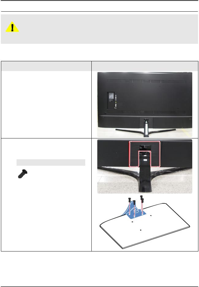
1 |
Carefully position the TV so that the screen |
|
is facing downwards. Make sure to place the |
|
|
|
TV upon a soft cushion or any material that |
|
|
will prevent damage to the screen. |
|
2 |
First, Remove 'Cover-Stand Decoration |
Rear'. And remove the 4 screws connecting |
the stand to the TV. Then carefully remove the stand.
Screws
6902-002474 x 4EA
TORQUE : 22.0 ~ 26.5lbf
3-1
3. Disassembly and Reassemble
|
Description |
Picture Description |
|
|
|
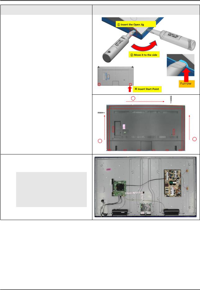
3 |
Remove the ASSY COVER P-REAR. |
|
• Insert Open Jig in a Disassembly furrow |
|
|
|
to Open the furrow. |
|
|
And Move Open Jig to the side. |
|
|
• Disassemble all Hooks of Cover Rear |
3 Jig direction |
|
along the three side. |
|
|
Jig direction |
Jig direction |
|
1 |
2 |
|
|
|
4 |
images.Remove the Electric tapes shown on the |
|
 NOTE
NOTE
When assembling the TV, the electric tapes must be applied on the same locations. Please remember to take a picture of where the tapes were first applied.
3-2
3. Disassembly and Reassemble
|
Description |
Picture Description |
|||
|
|
|
|
|
|
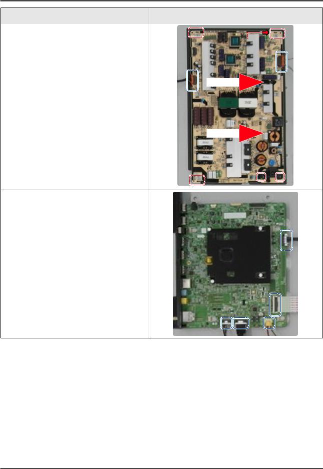
5 |
Remove the 'Lead Connectors' and screws |
|
|
|
|
from the SMPS unit. Then carefully remove |
|
|
|
|
|
|
Board Placing Point |
|
|||
|
the SMPS unit. |
|
|
||
|
|
||||
|
|
|
|
|
|
|
|
|
|
|
|
|
|
|
|
|
|
|
|
|
|
|
|
6 Remove the cables from the 'TV Board'.
3-3

3. Disassembly and Reassemble
|
Description |
Picture Description |
|
|
|
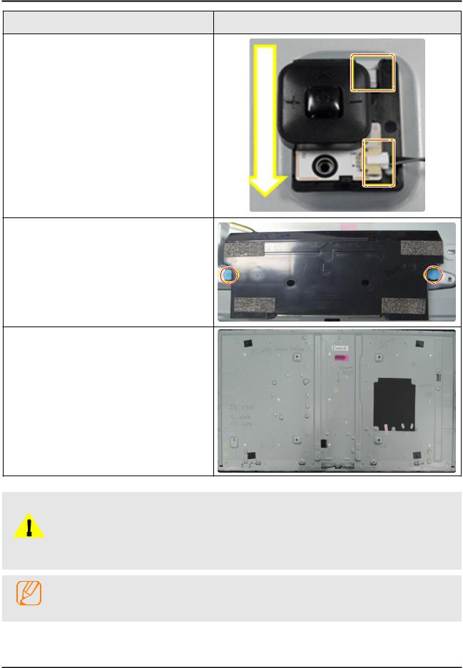
7 |
Use both hands to hold the 'Main Board' and |
|
gently lift up 2 point marked. |
|
8 |
Slide the board to the Left side to release the |
board. |
Then carefully remove the 'TV Board'.
9 Remove the BT/WIFI and IR unit.
3-4
3. Disassembly and Reassemble
Description |
Picture Description |
10 Remove the JOG unit.
11 Lastly, remove the speakers on both side.
*Panel
-Rear Side
1.Always remember to disconnect the Poewr Cord before assembling or disassembling the LED TV.
2.Always take precautions and follow the steps properly. Remember to take a picture before disassenbling.
CAUTION 3. Recommeded screwdriver torque :
•The torque may need to be adjusted accordingly.
Reassembly procedures are in the reverse order of disassembly procedures.
NOTE
3-5
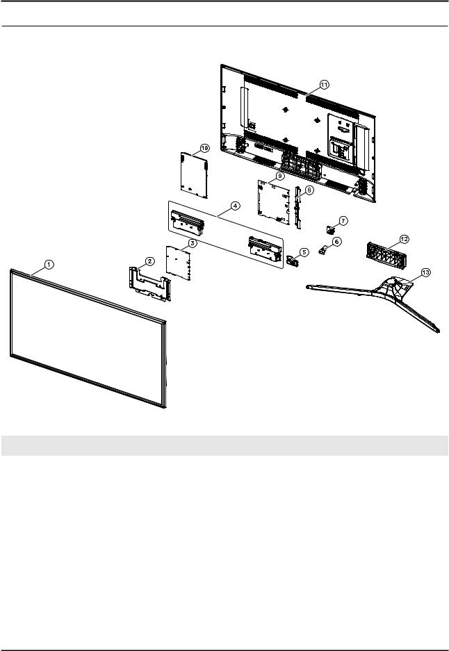
ANNEX. Exploded View & Part List
ANNEX. Exploded View & Part List [UE70KU6072UXXH EA01]
1-1. Exploded View
1-1-1. Parts List
No. |
Code No. |
Description & Specification |
Q’ty |
SA/SNA |
Remark |
|
|
|
|
|
|
1 |
BN95-02682A |
PRODUCT LCD-SHARP; CY-GK070HGSV1V/H,KU |
1 |
SA |
|
2 |
BN61-13606A |
BRACKET-STAND LINK; 55KU6400,EGI-SECC,T1. |
1 |
SNA |
|
3 |
BN95-02753A |
ASSY T CON; KU6000 Sharp 70inch,Hawk-UFT |
1 |
SA |
|
4 |
BN96-35006F |
ASSY SPEAKER P-FRONT; TV-SPK,KU6000,6ohm, |
1 |
SA |
|
5 |
BN59-01174D |
NETWORK-WLAN CLIENT; WIDT30Q,58x31.45x8.5 |
1 |
SA |
|
|
|
|
|
|
|
6 |
BN96-39955A |
ASSY BOARD P-IR FUNCTION; KU6000,IR ASSY_ |
1 |
SA |
|
|
|
|
|
|
|
7 |
BN96-35345B |
ASSY BOARD P-FUNCTION JOG; JU7500,CT15 |
1 |
SA |
|
|
|
|
|
|
|
8 |
BN63-15215A |
COVER-TERMINAL SIDE; 55KU6000,HIPS,MOLD,H |
1 |
SA |
|
|
|
|
|
|
|
9 |
BN94-10804L |
ASSY PCB MAIN; LEDTV 6K |
1 |
SA |
|
|
|
|
|
|
|
10 |
BN44-00874A |
DC VSS-PD BOARD; L75S5N_KHS,AC/DC,357W,10 |
1 |
SA |
|
|
|
|
|
|
|
11 |
BN96-40431G |
ASSY COVER P-REAR; 70KU6000,PC+ABS+GF1 |
1 |
SA |
|
12 |
BN96-40158B |
ASSY GUIDE P-STAND; 70KU6000,PC+ABS,BK000 |
1 |
SA |
|
13 |
BN96-40162C |
ASSY STAND P-BOTTOM; 70KU6000,PC+ABS,BK |
1 |
SA |
|
ANNEX-1
ANNEX. Exploded View & Part List
2-1. Electrical Parts List
Service Bom (SA: SERVICE AVAILABLE, SNA: SERVICE NOT AVAILABLE)
Level |
Location No. |
Code No. |
Description & Specification |
Q’ty |
SA/SNA |
Remark |
|
|
|
|
|
|
|
|
|
|
UE70KU6072UXXH (EA01) |
|
|
|
|
|
|
|
|
|
|
1 |
R001A |
BN90-08004F |
ASSY COVER REAR;LEDTV 6K |
1 |
SNA |
|
0.2 |
R001A |
BN96-40431G |
ASSY COVER P-REAR;70KU6000,PC+ABS+GF15%, |
1 |
SA |
|
|
|
|
|
|
|
|
..3 |
R001 |
BN63-15216B |
COVER-REAR;70KU6000,PC+ABS+GF15%,MOLD |
1 |
SNA |
|
,V- |
|
|||||
|
|
|
|
|
|
|
...4 |
|
0103-010275 |
RESIN PC ABS;235GNH15/6919H,Black,BK0007 |
5700 |
SNA |
|
..3 |
|
BN64-03529D |
INLAY-TERMINAL SIDE;55KU6500,PET,T0.125, |
1 |
SNA |
|
|
|
|
|
|
|
|
..3 |
|
BN68-03518R |
LABEL-STICKER CI SLOT;55KU6000,PET,T0.12 |
1 |
SNA |
|
|
|
|
|
|
|
|
..3 |
|
BN68-07835C |
LABEL-STICKER LICENSE;40K5500,PET,T0.125 |
1 |
SNA |
|
|
|
|
|
|
|
|
1 |
|
BN90-08029G |
ASSY W/I;LEDTV 6K |
1 |
SNA |
|
|
|
|
|
|
|
|
0.2 |
|
BN81-08159Z |
A/S PART SET-ELEC W/I;LED TV ELEC spec-C |
1 |
SNA |
|
0.2 |
|
BN81-11259Q |
A/S PART SET-MECH W/I;UKU6000P,U70KP* |
1 |
SNA |
|
|
|
|
|
|
|
|
1 |
S001A |
BN90-08065F |
ASSY STAND;LEDTV 6K |
1 |
SNA |
|
0.2 |
SG01A |
BN96-40158B |
ASSY GUIDE P-STAND;70KU6000,PC+ABS,BK000 |
1 |
SA |
|
|
|
|
|
|
|
|
..3 |
SCREW |
6003-000133 |
SCREW-TAPTYPE;BH,+,-,S,M4,L8,ZPC(BLK),SW |
9 |
SA |
|
..3 |
|
6902-002656 |
BAG PE;HDPE/PE FOAM,T0.015/T0.5,W180,L60 |
1 |
SNA |
|
|
|
|
|
|
|
|
..3 |
|
BN61-11629A |
BRACKET-STAND NECK;EGI-SECC,NATURAL,T1.2 |
1 |
SNA |
|
|
|
|
|
|
|
|
..3 |
|
BN61-13603A |
BRACKET-STAND NECK;65KU6500,HGI,T3,NATUR |
1 |
SNA |
|
..3 |
|
BN61-13605A |
BRACKET-STAND NECK FRONT;70KU6000,HGI,T2 |
1 |
SNA |
|
|
|
|
|
|
|
|
..3 |
|
BN63-11875X |
SHEET-PROTECTION COVER;55KS7000,PO,T0.06 |
1 |
SNA |
|
..3 |
|
BN63-15465A |
COVER-STAND NECK |
1 |
SNA |
|
|
FRONT;65KU6400,PC+ABS,M |
|
||||
|
|
|
|
|
|
|
..3 |
|
BN63-15469A |
COVER-STAND NECK |
1 |
SNA |
|
|
REAR;65KU6400,PC+ABS,MO |
|
||||
|
|
|
|
|
|
|
..3 |
|
BN63-15471A |
COVER-STAND NECK;65KU6400,PC+ABS,MOLD,V- |
1 |
SNA |
|
..3 |
|
BN96-29120M |
ASSY ACCESSORY-SCREW;LED_H8000,BN61- |
1 |
SNA |
|
|
0949 |
|
||||
|
|
|
|
|
|
|
...4 |
SCREW |
BN61-09494B |
SCREW-TAPTYPE;BH,+,S,M4,L14,ZPC(BLK),SWR |
8 |
SA |
|
|
|
|
|
|
|
|
...4 |
|
BN69-09241R |
BAG SCREW;LDPE,0.05,70,90,HU8500,Vinyl p |
1 |
SNA |
|
..3 |
|
BN96-40548A |
ASSY COVER P-STAND DECORATION;70KU6000,P |
1 |
SNA |
|
|
|
|
|
|
|
|
...4 |
|
BN61-13387A |
HOLDER-COVER;55KU6500,TPE,MOLD,BK0007,V2 |
4 |
SNA |
|
...4 |
|
BN63-15624A |
COVER-STAND DECORATION |
1 |
SNA |
|
|
REAR;70KU6000,PC+ |
|
||||
|
|
|
|
|
|
|
0.2 |
SB02A |
BN96-40162C |
ASSY STAND P-BOTTOM;70KU6000,PC+ABS,BK00 |
1 |
SA |
|
|
|
|
|
|
|
|
..3 |
SCREW |
6003-001001 |
SCREW-TAPTYPE;FH,+,-,B,M3,L8,ZPC(BLK),SW |
4 |
SA |
|
..3 |
SCREW |
6003-001086 |
SCREW-TAPTYPE;BH,+,-,B,M3,L12,ZPC(BLK),S |
4 |
SA |
|
|
|
|
|
|
|
|
..3 |
SCREW |
6003-001208 |
SCREW-TAPTYPE;BH,+,S,M4,L12,ZPC(BLK),SWR |
4 |
SA |
|
|
|
|
|
|
|
|
..3 |
|
6902-002461 |
BAG PE;HDPE/PE FOAM,T0.015/T0.5,W100,L60 |
2 |
SNA |
|
|
|
|
|
|
|
|
..3 |
|
6902-002550 |
BAG PE;HDPE/PE FOAM,T0.015/T0.5,W200,L50 |
1 |
SNA |
|
|
|
|
|
|
|
|
..3 |
|
BN60-00162E |
SPACER-FOAM;PE FOAM,L50M,GRAY,T0.5,W20 |
1 |
SNA |
|
..3 |
|
BN61-05728A |
TAPE-DOUBLE FACE;ACRYL,T0.4,W10,L30M,GRA |
1 |
SNA |
|
|
|
|
|
|
|
|
..3 |
|
BN61-11533A |
BRACKET-STAND NECK;Al,NATURAL |
1 |
SNA |
|
..3 |
|
BN61-11556A |
BRACKET-STAND NECK;Al,NATURAL |
1 |
SNA |
|
|
|
|
|
|
|
|
..3 |
|
BN63-15461A |
COVER-STAND TOP;65KU6400,PC+ABS,MOLD,V-0 |
1 |
SNA |
|
...4 |
|
0103-005041 |
RESIN PC ABS;FR3200TV,901408,BK0008,1.2m |
260 |
SNA |
|
|
|
|
|
|
|
|
ANNEX-2

ANNEX. Exploded View & Part List
Level |
Location No. |
Code No. |
Description & Specification |
Q’ty |
SA/SNA |
Remark |
|
|
|
|
|
|
|
...4 |
|
BN63-11118P |
SHEET-PROTECTION COVER;55K6200,PET,T0.04 |
1 |
SNA |
|
|
|
|
|
|
|
|
..3 |
|
BN63-15490A |
COVER-STAND BOTTOM;65KU6400,HIPS,MOLD,V- |
1 |
SNA |
|
..3 |
RF01 |
BN67-00398L |
FOOT-RUBBER;UH6K,Si,GRAY,W8,L15.5,T2 |
8 |
SNA |
|
|
|
|
|
|
|
|
..3 |
|
BN68-05603A |
LABEL-E PASS;ART PAPER 90G,W/W |
3 |
SNA |
|
1 |
M0017 |
BN91-17281J |
ASSY CHASSIS;LEDTV 6K |
1 |
SNA |
|
|
|
|
|
|
|
|
0.2 |
M0014 |
BN94-10804L |
ASSY PCB MAIN;LEDTV 6K |
1 |
SA |
|
..3 |
|
BN62-00817A |
HEAT SINK-PS;55KU6000,A1050,T1.5,W115,L1 |
1 |
SNA |
|
|
|
|
|
|
|
|
..3 |
|
BN63-15215A |
COVER-TERMINAL SIDE;55KU6000,HIPS,MOLD,H |
1 |
SA |
|
|
|
|
|
|
|
|
..3 |
|
BN97-10654G |
ASSY SMD;LED TV 6K |
1 |
SNA |
|
|
|
|
|
|
|
|
...4 |
DS01A |
0401-001056 |
DIODE-SWITCHING;MMBD4148SE,100V,200mA,SO |
1 |
SA |
|
|
|
|
|
|
|
|
...4 |
|
0403-001783 |
DIODE-ZENER;BZB84-C6V2,5.8~6.6V,300mW,SO |
3 |
SNA |
|
...4 |
|
0404-001404 |
DIODE-SCHOTTKY;BAT721C,40V,200mA,SOT-23, |
4 |
SA |
|
|
|
|
|
|
|
|
...4 |
|
0404-001881 |
DIODE-SCHOTTKY;SS3040-HE,40V,3000mA,SOD- |
5 |
SA |
|
...4 |
|
0406-001200 |
DIODE-TVS;RClamp0504F,6V,1MAV,TP |
2 |
SA |
|
|
|
|
|
|
|
|
...4 |
|
0406-001290 |
DIODE-TVS;3.0SMCJ20A,22.2V,24.5V,5MAV,30 |
1 |
SNA |
|
...4 |
|
0406-001628 |
DIODE-TVS;AOZ8804ADI,6V,1MAV,5A,TP |
1 |
SA |
|
|
|
|
|
|
|
|
...4 |
|
0406-001635 |
DIODE-TVS;SMF5.0A,6.4V,6.7V,7V,200MAV,20 |
1 |
SA |
|
|
|
|
|
|
|
|
...4 |
|
0501-000002 |
TR-SMALL SIGNAL;KSA812,PNP,150mW,SOT-23, |
1 |
SNA |
|
...4 |
|
0501-000445 |
TR-SMALL SIGNAL;KTC3875S-Y,NPN,150mW,SOT |
7 |
SC |
|
|
|
|
|
|
|
|
...4 |
|
0504-000126 |
TR-DIGITAL;KSR1101,NPN,200mW,4.7K/4.7K,S |
1 |
SA |
|
...4 |
|
0505-001844 |
FET-SILICON;SI4435DDY-T1-GE3,P,30V,-11.4 |
1 |
SA |
|
|
|
|
|
|
|
|
...4 |
|
0505-002560 |
FET-SILICON;AO6415,P,20V,-3.3A,0.15ohm,1 |
1 |
SA |
|
|
|
|
|
|
|
|
...4 |
|
0505-002598 |
FET-SILICON;AP2317GN,P,20V,-4.2A,0.052oh |
1 |
SA |
|
|
|
|
|
|
|
|
...4 |
|
0505-002893 |
FET-SILICON;AO4801AS,P,30V,-5A,2W,SOIC-8 |
2 |
SA |
|
|
|
|
|
|
|
|
...4 |
|
0505-003397 |
FET-SILICON;2N7002K,N,60V,0.38A,1.19ohm, |
1 |
SA |
|
...4 |
|
0801-003603 |
IC-CMOS LOGIC;MC74LCX244MN2TWG,Octal buf |
1 |
SA |
|
|
|
|
|
|
|
|
...4 |
|
1001-001998 |
IC-ANALOG MULTIPLEX;NX3DV221GM,USB switc |
2 |
SA |
|
...4 |
|
1103-001564 |
IC-EEPROM;S-24C512CI-J800,512Kbit,64Kx8, |
1 |
SA |
|
|
|
|
|
|
|
|
...4 |
|
1105-002704 |
IC-DDR4 SDRAM;K4F8E304HB-MGCH,LPDDR4- |
2 |
SA |
|
|
SDR |
|
||||
|
|
|
|
|
|
|
...4 |
|
1201-000166 |
IC-OP AMP;LM358,SOP,ST,8P,150MIL,DUAL,10 |
1 |
SA |
|
...4 |
|
1201-003690 |
IC-AUDIO AMP;TAS5747PHPR,QFP,48P,DUAL,PL |
1 |
SA |
|
|
|
|
|
|
|
|
...4 |
|
1203-004364 |
IC-VOL. DETECTOR;RT9818C-42PV,SOT-23,3P, |
1 |
SA |
|
...4 |
|
1203-008102 |
IC-POSI.FIXED REG.;S-13A1D12-E800,HSOP,8 |
1 |
SNA |
|
|
|
|
|
|
|
|
...4 |
|
1203-008104 |
IC-POSI.FIXED REG.;S-13A1D18-E800,HSOP,8 |
1 |
SNA |
|
...4 |
|
1203-008105 |
IC-POSI.FIXED REG.;S-13A1D33-E800,HSOP,8 |
1 |
SNA |
|
|
|
|
|
|
|
|
...4 |
|
1203-008391 |
IC-DC/DC CONVERTER;AOZ1269QI-02,QFN-23L, |
2 |
SA |
|
|
|
|
|
|
|
|
...4 |
|
1203-008392 |
IC-VOL. DETECTOR;S-6414AAB-L800X,TSOT-23 |
1 |
SA |
|
...4 |
|
1203-008448 |
IC-DC/DC CONVERTER;A8305SESTR-T,QFN,16,3 |
1 |
SNA |
|
|
|
|
|
|
|
|
...4 |
|
1203-008454 |
IC-DC/DC CONVERTER;TPS56528,HSOP8,8,4,89 |
2 |
SA |
|
...4 |
|
1203-008522 |
IC-DC/DC CONVERTER;SN1501019DDCR,SOT-23, |
2 |
SNA |
|
|
|
|
|
|
|
|
...4 |
|
1203-008732 |
IC-DC/DC CONVERTER;SYD104ADC,TSOT-23,6,3 |
1 |
SA |
|
...4 |
|
1203-008733 |
IC-DC/DC CONVERTER;AOZ1236QI-02,QFN,23,4 |
2 |
SA |
|
|
|
|
|
|
|
|
...4 |
|
1204-003697 |
IC-DECODER;SDP1531,FCPBGA,1046P,31x31,GL |
1 |
SA |
|
|
|
|
|
|
|
|
...4 |
|
1205-004822 |
IC-SWITCH;TPS22965DSGR,SON,8P,2x2x0.75mm |
3 |
SNA |
|
...4 |
|
1205-005325 |
IC-REPEATER;PS8409QFN48GTR2-A1,QFN,48P,6 |
1 |
SA |
|
|
|
|
|
|
|
|
...4 |
|
1205-005519 |
IC-SWITCH;ET20163,SOT23-5,5P,2.95x3.02mm |
3 |
SA |
|
ANNEX-3

ANNEX. Exploded View & Part List
Level |
Location No. |
Code No. |
Description & Specification |
Q’ty |
SA/SNA |
Remark |
|
|
|
|
|
|
|
...4 |
|
1405-001232 |
VARISTOR;6.4V,5.6VDC,30A,1608,TP,19V,200 |
2 |
SNA |
|
...4 |
|
1405-001271 |
VARISTOR;35V,20VDC,5A,1005,TP,100V,10pF |
15 |
SA |
|
...4 |
|
2007-000039 |
R-CHIP;0ohm,1%,1/10W,TP,1608 |
4 |
SA |
|
|
|
|
|
|
|
|
...4 |
|
2007-000173 |
R-CHIP;22ohm,5%,1/16W,TP,1005 |
3 |
SNA |
|
...4 |
|
2007-000683 |
R-CHIP;3.3Kohm,1%,1/10W,TP,1608 |
1 |
SA |
|
|
|
|
|
|
|
|
...4 |
|
2007-000932 |
R-CHIP;470ohm,5%,1/16W,TP,1005 |
3 |
SNA |
|
...4 |
|
2007-001125 |
R-CHIP;68Kohm,1%,1/10W,TP,1608 |
2 |
SA |
|
|
|
|
|
|
|
|
...4 |
|
2007-001288 |
R-CHIP;18ohm,5%,1/16W,TP,1005 |
4 |
SA |
|
...4 |
|
2007-001292 |
R-CHIP;33ohm,5%,1/16W,TP,1005 |
28 |
SNA |
|
|
|
|
|
|
|
|
...4 |
|
2007-007107 |
R-CHIP;100Kohm,1%,1/16W,TP,1005 |
16 |
SNA |
|
|
|
|
|
|
|
|
...4 |
|
2007-007131 |
R-CHIP;13Kohm,1%,1/16W,TP,1005 |
2 |
SA |
|
...4 |
|
2007-007132 |
R-CHIP;15Kohm,1%,1/16W,TP,1005 |
2 |
SA |
|
|
|
|
|
|
|
|
...4 |
|
2007-007137 |
R-CHIP;1.2Kohm,1%,1/16W,TP,1005 |
3 |
SA |
|
...4 |
|
2007-007138 |
R-CHIP;27Kohm,1%,1/16W,TP,1005 |
3 |
SNA |
|
|
|
|
|
|
|
|
...4 |
|
2007-007310 |
R-CHIP;8.2Kohm,1%,1/16W,TP,1005 |
1 |
SA |
|
|
|
|
|
|
|
|
...4 |
|
2007-007312 |
R-CHIP;20Kohm,1%,1/16W,TP,1005 |
13 |
SA |
|
|
|
|
|
|
|
|
...4 |
|
2007-007313 |
R-CHIP;6.8Kohm,1%,1/16W,TP,1005 |
3 |
SA |
|
|
|
|
|
|
|
|
...4 |
|
2007-007334 |
R-CHIP;200Kohm,1%,1/16W,TP,1005 |
5 |
SNA |
|
...4 |
|
2007-007528 |
R-CHIP;1.5Kohm,1%,1/16W,TP,1005 |
5 |
SA |
|
|
|
|
|
|
|
|
...4 |
|
2007-007720 |
R-CHIP;300Kohm,1%,1/10W,TP,1608 |
1 |
SA |
|
...4 |
|
2007-007723 |
R-CHIP;75Kohm,1%,1/10W,TP,1608 |
2 |
SA |
|
|
|
|
|
|
|
|
...4 |
|
2007-007767 |
R-CHIP;200ohm,1%,1/16W,TP,1005 |
7 |
SA |
|
...4 |
|
2007-007798 |
R-CHIP;10ohm,1%,1/16W,TP,1005 |
8 |
SA |
|
|
|
|
|
|
|
|
...4 |
|
2007-007847 |
R-CHIP;16Kohm,1%,1/10W,TP,1608 |
5 |
SA |
|
|
|
|
|
|
|
|
...4 |
|
2007-007942 |
R-CHIP;1Mohm,1%,1/16W,TP,1005 |
1 |
SNA |
|
...4 |
|
2007-007981 |
R-CHIP;180Kohm,1%,1/16W,TP,1005 |
1 |
SNA |
|
|
|
|
|
|
|
|
...4 |
|
2007-008015 |
R-CHIP;75ohm,1%,1/16W,TP,1005 |
9 |
SNA |
|
...4 |
|
2007-008263 |
R-CHIP;3Kohm,1%,1/16W,TP,1005 |
2 |
SA |
|
|
|
|
|
|
|
|
...4 |
|
2007-008269 |
R-CHIP;51Kohm,1%,1/16W,TP,1005 |
3 |
SA |
|
...4 |
|
2007-008298 |
R-CHIP;49.9ohm,1%,1/16W,TP,1005 |
4 |
SA |
|
|
|
|
|
|
|
|
...4 |
|
2007-008391 |
R-CHIP;6.34Kohm,1%,1/16W,TP,1005 |
2 |
SA |
|
|
|
|
|
|
|
|
...4 |
|
2007-008779 |
R-CHIP;0ohm,1%,1/16W,TP,1005 |
2 |
SA |
|
...4 |
|
2007-009117 |
R-CHIP;49.9Kohm,1%,1/16W,TP,1005 |
1 |
SA |
|
|
|
|
|
|
|
|
...4 |
|
2007-009322 |
R-CHIP;1.3Kohm,1%,1/16W,TP,1005 |
2 |
SA |
|
...4 |
|
2011-001261 |
R-NETWORK;33ohm,5%,1/16W,L,CHIP,8P,TP,2. |
6 |
SA |
|
|
|
|
|
|
|
|
...4 |
|
2011-001344 |
R-NETWORK;100ohm,5%,1/16W,L,CHIP,8P,TP,2 |
6 |
SA |
|
...4 |
AD480 |
2203-000233 |
C-CER,CHIP;0.1nF,5%,50V,C0G,TP,1005 |
4 |
SA |
|
|
|
|
|
|
|
|
...4 |
AD480 |
2203-000278 |
C-CER,CHIP;0.01nF,0.5pF,50V,C0G,TP,1005 |
2 |
SA |
|
|
|
|
|
|
|
|
...4 |
AD480 |
2203-000359 |
C-CER,CHIP;0.15nF,5%,50V,C0G,TP,1005,0.5 |
3 |
SNA |
|
...4 |
AD480 |
2203-000386 |
C-CER,CHIP;0.015nF,5%,50V,C0G,TP,1005 |
3 |
SA |
|
|
|
|
|
|
|
|
...4 |
AD480 |
2203-000438 |
C-CER,CHIP;1nF,10%,50V,X7R,TP,1005 |
12 |
SA |
|
...4 |
AD480 |
2203-000585 |
C-CER,CHIP;0.22nF,10%,50V,X7R,TP,1005 |
3 |
SA |
|
|
|
|
|
|
|
|
...4 |
AD480 |
2203-000812 |
C-CER,CHIP;0.033nF,5%,50V,C0G,TP,1005 |
9 |
SA |
|
...4 |
AD480 |
2203-000940 |
C-CER,CHIP;0.47nF,10%,50V,X7R,TP,1005 |
2 |
SA |
|
|
|
|
|
|
|
|
...4 |
AD480 |
2203-002285 |
C-CER,CHIP;10nF,10%,50V,X7R,TP,1005 |
6 |
SNA |
|
|
|
|
|
|
|
|
...4 |
AD480 |
2203-005054 |
C-CER,CHIP;0.0047nF,0.25pF,50V,NP0,TP,10 |
2 |
SA |
|
...4 |
AD480 |
2203-005083 |
C-CER,CHIP;220nF,10%,50V,X7R,TP,1608,T0. |
8 |
SA |
|
|
|
|
|
|
|
|
ANNEX-4

ANNEX. Exploded View & Part List
Level |
Location No. |
Code No. |
Description & Specification |
Q’ty |
SA/SNA |
Remark |
|
|
|
|
|
|
|
...4 |
AD480 |
2203-006126 |
C-CER,CHIP;47nF,10%,16V,X7R,TP,1005 |
3 |
SNA |
|
...4 |
AD480 |
2203-006324 |
C-CER,CHIP;2200nF,10%,10V,X5R,TP,1608 |
14 |
SA |
|
...4 |
AD480 |
2203-006562 |
C-CER,CHIP;1000nF,10%,10V,X5R,TP,1005 |
23 |
SNA |
|
|
|
|
|
|
|
|
...4 |
AD480 |
2203-006824 |
C-CER,CHIP;4700nF,10%,10V,X5R,TP,1608 |
5 |
SNA |
|
...4 |
AD480 |
2203-006838 |
C-CER,CHIP;2200nF,10%,6.3V,X5R,TP,1005 |
9 |
SA |
|
|
|
|
|
|
|
|
...4 |
AD480 |
2203-006844 |
C-CER,CHIP;470nF,10%,10V,X5R,TP,1005 |
2 |
SA |
|
...4 |
AD480 |
2203-006960 |
C-CER,CHIP;1000nF,10%,50V,X7R,TP,2012 |
2 |
SNA |
|
|
|
|
|
|
|
|
...4 |
AD480 |
2203-007306 |
C-CER,CHIP;10000nF,10%,25V,X5R,TP,2012,1 |
28 |
SNA |
|
...4 |
AD480 |
2203-007544 |
C-CER,CHIP;100nF,10%,50V,X7R,TP,1005,T0. |
66 |
SA |
|
|
|
|
|
|
|
|
...4 |
AD480 |
2203-008315 |
C-CER,CHIP;22000nF,20%,25V,X5R,TP,2012,T |
8 |
SA |
|
|
|
|
|
|
|
|
...4 |
|
2402-001268 |
C-AL,SMD;100uF,20%,25V,WT,TP,8x6.3mm |
1 |
SA |
|
...4 |
|
2703-000213 |
INDUCTOR-SMD;470nH,10%,1.35Ohm,35mA,15,M |
1 |
SA |
|
|
|
|
|
|
|
|
...4 |
|
2703-002269 |
INDUCTOR-SMD;56nH,5%,1005,0.5T,1.4Ohm,15 |
7 |
SA |
|
...4 |
|
2703-003149 |
INDUCTOR-SMD;2.2uH,20%,0.055Ohm,3000mA,W |
1 |
SA |
|
|
|
|
|
|
|
|
...4 |
|
2703-004630 |
INDUCTOR-SMD;2.2uH,20%,5.0T,0.0025Ohm,66 |
1 |
SNA |
|
|
|
|
|
|
|
|
...4 |
|
2703-004724 |
INDUCTOR-SMD;8.2uH,20%,4T,0.072Ohm,2300m |
4 |
SA |
|
|
|
|
|
|
|
|
...4 |
|
2703-005191 |
INDUCTOR-SMD;1.5uH,20%,6060,T4.5,0.02Ohm |
1 |
SA |
|
|
|
|
|
|
|
|
...4 |
|
2703-005193 |
INDUCTOR-SMD;2.2uH,20%,4.5,0.024Ohm,5100 |
2 |
SA |
|
...4 |
|
2703-005198 |
INDUCTOR-SMD;15uH,20%,3T,0.123Ohm,2500mA |
1 |
SNA |
|
|
|
|
|
|
|
|
...4 |
|
2801-004021 |
CRYSTAL-SMD;24.576MHz,20ppm,28-AAN,12pF, |
1 |
SA |
|
...4 |
|
3301-001364 |
BEAD-SMD;1000ohm,1608,TP,1085ohm/108MHz, |
6 |
SNA |
|
|
|
|
|
|
|
|
...4 |
|
3601-001374 |
FUSE-SURFACE MOUNT;32V,5A,FAST-ACTING,PL |
3 |
SA |
|
...4 |
|
3601-001376 |
FUSE-SURFACE MOUNT;32V,3A,FAST-ACTING,Hi |
3 |
SNA |
|
|
|
|
|
|
|
|
...4 |
|
3701-001967 |
CONNECTOR-HDMI;19P,A,FEMALE,AU,0.5mm,BLK |
3 |
SA |
|
|
|
|
|
|
|
|
...4 |
|
3707-001103 |
CONNECTOR-OPTICAL;ANGLE,SPDIF,2.5PI |
1 |
SA |
|
...4 |
|
3710-003908 |
CONNECTOR-SOCKET;64P,2R,0.5mm,SMD-S,AU,B |
1 |
SA |
|
|
|
|
|
|
|
|
...4 |
EH01 |
3711-007803 |
HEADER-BOARD TO CABLE;BOX,12P,1R,1.25mm, |
1 |
SA |
|
...4 |
EH01 |
3711-008131 |
HEADER-BOARD TO CABLE;BOX,4P,1R,2.5mm,AN |
1 |
SA |
|
|
|
|
|
|
|
|
...4 |
EH01 |
3711-008859 |
HEADER-BOARD TO CABLE;BOX,12P,2R,2mm,ANG |
1 |
SA |
|
...4 |
|
3711-009090 |
CONNECTOR-HEADER;BOX,16P,1R,1.25mm,SMD-A |
1 |
SA |
|
|
|
|
|
|
|
|
...4 |
|
3722-003199 |
JACK-MODULAR;8P/8C,Y,ANGLE,NONE,AU,1PORT |
1 |
SA |
|
|
|
|
|
|
|
|
...4 |
|
3722-003457 |
JACK-USB;4P/1C,NI,BLK,ANGLE,A,2.0,13.1x1 |
2 |
SA |
|
...4 |
|
3722-003814 |
JACK-PHONE;1P/7C,NI/SN,YEL,ANGLE,3.5PI,1 |
1 |
SA |
|
|
|
|
|
|
|
|
...4 |
JACK |
3722-003873 |
JACK-PHONE;1P/7C,AU/SN,BLU,ANGLE,3.5PI,1 |
1 |
SA |
|
...4 |
|
6302-001376 |
GASKET-SMD;,,CONDUCTIVE FABRIC,T14,W43,L |
7 |
SNA |
|
|
|
|
|
|
|
|
...4 |
|
BN40-00323A |
TUNER-DTV AIR CABLE SAT;DTOS24EH6A,DTOS2 |
1 |
SA |
|
...4 |
|
BN41-02528A |
PCB-MAIN;KU6000,FR-4,4L,1.6T,193x241mm,1 |
1 |
SNA |
|
|
|
|
|
|
|
|
...4 |
CB07 |
BN61-13312B |
BRACKET-SCREWLESS PCB;55KS8000,SK5,T0.3, |
4 |
SNA |
|
|
|
|
|
|
|
|
...4 |
|
BN97-10863B |
ASSY MICOM-SUB;JMMICOM_EU_ |
1 |
SNA |
|
|
TV,UWP60,W25Q4 |
|
||||
|
|
|
|
|
|
|
....5 |
|
1107-002226 |
IC-NOR FLASH;W25Q40CLSSIP,4Mbit,SOIC,8P, |
1 |
SA |
|
|
|
|
|
|
|
|
...4 |
|
BN97-10865A |
ASSY MICOM-MAIN;T-JZL6DEUC,UWP60,KLM4G1F |
1 |
SNA |
|
....5 |
|
1107-002374 |
IC-EMMC;KLM4G1FEPD-B031,4Gbyte,BGA,153P, |
1 |
SNA |
|
|
|
|
|
|
|
|
..3 |
|
BN97-10916A |
ASSY DRM;JAZZ-L,DVB,NagSam, MAC, HDCP, C |
1 |
SNA |
|
|
|
|
|
|
|
|
...4 |
|
BN46-00109H |
KEY CODE-CERTIFICATION;MAC,TV/AV,General |
1 |
SNA |
|
...4 |
|
BN46-00110P |
KEY CODE-CERTIFICATION;MIRACAST(HDCP2.2) |
1 |
SNA |
|
|
|
|
|
|
|
|
...4 |
|
BN46-00500A |
KEY CODE-CERTIFICATION;JAZZ-L,Nagra CSC |
1 |
SNA |
|
ANNEX-5

ANNEX. Exploded View & Part List
Level |
Location No. |
Code No. |
Description & Specification |
Q’ty |
SA/SNA |
Remark |
|
|
|
|
|
|
|
...4 |
|
BN46-00514A |
KEY CODE-CERTIFICATION;CI PLUS,Jazz M, J |
1 |
SNA |
|
|
|
|
|
|
|
|
1 |
|
BN91-17313C |
ASSY SHIELD;LEDTV 6K |
1 |
SNA |
|
0.2 |
SCREW |
6001-003081 |
SCREW-MACHINE;PWH,+,M3,L5,ZPC(WHT),SWR |
2 |
SA |
|
CH |
|
|||||
|
|
|
|
|
|
|
0.2 |
|
BN02-00102B |
TAPE-SINGLE FACE;FILAMENT,#8917,T0.15,W2 |
0 |
SNA |
|
0.2 |
|
BN39-02217F |
LEAD CONNECTOR-POWER;70KU6000,UL21016,12 |
1 |
SA |
|
|
|
|
|
|
|
|
0.2 |
|
BN39-02218C |
LEAD CONNECTOR-SUB ASSY;65KU6000,UL21016 |
1 |
SA |
|
|
|
|
|
|
|
|
0.2 |
|
BN39-02220D |
LEAD CONNECTOR-SUB ASSY;65KU6300,UL21016 |
1 |
SA |
|
0.2 |
|
BN39-02245A |
LEAD CONNECTOR-BLU;70KU6000,UL21016,16P, |
1 |
SA |
|
|
|
|
|
|
|
|
0.2 |
|
BN44-00874A |
DC VSS-PD BOARD;L75S5N_KHS,AC/DC,357W,10 |
1 |
SA |
|
0.2 |
WIFI |
BN59-01174D |
NETWORK-WLAN CLIENT;WIDT30Q,58x31.45x8.5 |
1 |
SA |
|
|
|
|
|
|
|
|
0.2 |
|
BN61-05914A |
TAPE DOUBLE FACE;65LB650,ACRYL FOAM,T1.1 |
0 |
SNA |
|
|
|
|
|
|
|
|
0.2 |
|
BN61-10073B |
HOLDER-WIFI;55KU6000,ABS,MOLD,BK0007,HB |
1 |
SNA |
|
|
|
|
|
|
|
|
0.2 |
|
BN96-35006F |
ASSY SPEAKER P-FRONT;TV-SPK,KU6000,6ohm, |
1 |
SA |
|
|
|
|
|
|
|
|
0.2 |
JOG |
BN96-35345B |
ASSY BOARD P-FUNCTION JOG;JU7500,CT15SE8 |
1 |
SA |
|
..3 |
AH240 |
BN61-11584A |
HOLDER-BUTTON;JU7500,ABS,MOLD,BK0007,HB |
1 |
SNA |
|
|
|
|
|
|
|
|
..3 |
AH297 |
BN63-11231B |
HOLDER-KNOB;HU7000,ABS,MOLD,BLACK,HB |
1 |
SNA |
|
..3 |
FK04 |
BN64-02406B |
BUTTON-FUNCTION;LED_HU7000,ABS,HB,BLACK, |
1 |
SNA |
|
|
|
|
|
|
|
|
...4 |
|
0103-004609 |
RESIN ABS;HF-0680U,K21294,BK0007,HB,High |
8 |
SNA |
|
0.2 |
|
BN96-36274J |
FFC CABLE;50J6200,Fold,L500,51P |
1 |
SA |
|
|
|
|
|
|
|
|
0.2 |
|
BN96-39955A |
ASSY BOARD P-IR FUNCTION;KU6000,IR ASSY_ |
1 |
SA |
|
0.2 |
T0382 |
BP61-00492C |
TAPE SINGLE FACE;ACRYL,PJT,ACRYL FOAM,T0 |
2 |
SNA |
|
1 |
|
BN92-19850M |
ASSY BOX;LEDTV 6K |
1 |
SNA |
|
|
|
|
|
|
|
|
0.2 |
|
BH68-00662A |
LABEL BOX;ALL,ART PAPER,W60,L110,WHT,NO |
1 |
SNA |
|
0.2 |
|
BN68-05640A |
LABEL BOX;ALL,ART PAPER,W110,L130,EUROPE |
1 |
SNA |
|
|
|
|
|
|
|
|
0.2 |
|
BN69-13734F |
BOX UNIT-OUT;70KU6000,CB,DW4,F3,L1722,W2 |
1 |
SNA |
|
0.2 |
|
BN69-13735A |
BOX UNIT-IN;70KU6000,CB,DW1,C1,L2146,W55 |
1 |
SNA |
|
|
|
|
|
|
|
|
1 |
|
BN92-19880M |
ASSY LABEL;LEDTV 6K |
1 |
SNA |
|
0.2 |
|
0203-001598 |
TAPE-SINGLE FACE;FILAMENT,#8915,T0.15,W1 |
0 |
SNA |
|
|
|
|
|
|
|
|
0.2 |
|
BN68-06708G |
LABEL-RATING;Monitor,WW,PP,T0.161,W93,L7 |
1 |
SNA |
|
|
|
|
|
|
|
|
0.2 |
|
BN68-07519A |
LABEL-ENERGY;ALL JORDAN,WW,PP,T0.135,W60 |
1 |
SNA |
|
0.2 |
|
BN68-07874F |
LEAFLET-QUICK SETUP GUIDE;KU6000 70",EU, |
1 |
SNA |
|
|
|
|
|
|
|
|
1 |
ACCE1 |
BN92-19910P |
ASSY ACCESSORY;LEDTV 6K |
1 |
SNA |
|
0.2 |
ACCE4 |
BN96-35101J |
ASSY ACCESSORY-MANUAL;UE70KU6000WXXH |
1 |
SNA |
|
|
|
|
|
|
|
|
..3 |
|
6902-001964 |
BAG PE;LDPE,BIOBASED,T0.03,W200,L300,TRP |
1 |
SNA |
|
..3 |
T0527 |
BN68-00513A |
LABEL-E PASS;ALL MODEL,WW,YUPO,W50,L15,W |
2 |
SNA |
|
|
|
|
|
|
|
|
..3 |
|
BN68-03548J |
LEAFLET-WARRANTY;comm,Samsung,17Lang,Mid |
1 |
SNA |
|
|
|
|
|
|
|
|
..3 |
|
BN68-04972E |
LEAFLET-REGULATORY |
1 |
SNA |
|
|
GUIDE;ALL,SAMSUNG,W/W |
|
||||
|
|
|
|
|
|
|
..3 |
|
BN68-07598A |
LEAFLET-FICHE;ALL,W/P,0 |
1 |
SNA |
|
|
|
|
|
|
|
|
..3 |
|
BN68-08015T |
MANUAL USERS;KU6000,XH,W/P,EURO B5 |
1 |
SNA |
|
0.2 |
ACCE2 |
BN96-39490A |
ASSY ACCESSORY-CABLE;UE43KU6000KXZF |
1 |
SNA |
|
|
|
|
|
|
|
|
..3 |
|
3709-001791 |
CONNECTOR-CARD SLOT;64P,0.5mm,SMD-A,AU,P |
1 |
SA |
|
|
|
|
|
|
|
|
..3 |
T0268 |
3903-001118 |
CBF-POWER CORD;DT,EU,Angle,2P(C7),250V,2 |
1 |
SA |
|
..3 |
|
4301-000121 |
BATTERY-MN;1.5V,R03,10.5x44.5m,7.5g,AAA |
2 |
SNA |
|
|
|
|
|
|
|
|
..3 |
EC03 |
BN39-02189A |
GENDER CABLE;DC to RCA Cable,3P,L100,UL2 |
1 |
SA |
|
..3 |
EC03 |
BN39-02190A |
GENDER CABLE;DC to RCA Cable,2P,L100,UL2 |
1 |
SA |
|
|
|
|
|
|
|
|
..3 |
|
BN59-01247A |
REMOCON-TV;2016 TV,Samsung,44KEY,3V,KU60 |
1 |
SA |
|
|
|
|
|
|
|
|
ANNEX-6

ANNEX. Exploded View & Part List
Level |
Location No. |
Code No. |
Description & Specification |
Q’ty |
SA/SNA |
Remark |
|
|
|
|
|
|
|
..3 |
|
BN68-08097D |
LEAFLET;JAZZ-L,EUROPE,W/P,W200,L250,4COL |
1 |
SNA |
|
|
|
|
|
|
|
|
..3 |
|
BN68-08112A |
LABEL-SECURITY;ALL,PET,T0.05,W55,L52,GLO |
1 |
SNA |
|
..3 |
|
BN69-13918A |
BAG ACCESSORY;LDPE,T0.07,L350,W500,TRP,B |
1 |
SNA |
|
|
|
|
|
|
|
|
1 |
|
BN92-19940A |
ASSY P/MATERIAL;LEDTV 6K |
1 |
SNA |
|
0.2 |
|
6902-001954 |
BAG ROLL;HDPE/PE FOAM,HDPE T0.018mm,T0.2 |
4 |
SNA |
|
|
|
|
|
|
|
|
0.2 |
|
6902-002233 |
BAG AIR;LDPE,-,T0.2,W900,L1850,TRP,-,-,- |
1 |
SNA |
|
0.2 |
|
6922-000003 |
BAND;PP,T0.8,W18,L1650M,TRP,DA69-90145A |
6 |
SNA |
|
|
|
|
|
|
|
|
0.2 |
T0214 |
AA61-20285C |
HOLDER-BOX;ALL,PP,MOLD,BLACK,HB,HB,17.5g |
4 |
SNA |
|
0.2 |
|
BN02-00319B |
TAPE-SINGLE FACE;OPP,T0.05,W75,L800M,CLE |
3 |
SNA |
|
|
|
|
|
|
|
|
0.2 |
|
BN68-02422B |
LABEL WARNING;ALL,ART PAPER,T0.05,W240,L |
1 |
SNA |
|
|
|
|
|
|
|
|
0.2 |
|
BN69-03982L |
PACKING ANGLE;ALL,PAPER,-,-,-,-,-,-,- |
1 |
SNA |
|
0.2 |
|
BN69-05418M |
WRAP;T0.017,500,2000000,2000000,500 |
0 |
SNA |
|
|
|
|
|
|
|
|
0.2 |
|
BN69-06640E |
PAD-PACKING;TRUCK PAD,CB,-,,W410,L2500,, |
1 |
SNA |
|
0.2 |
|
BN69-06642A |
PAD-DP SHEET;PAD,CB,SW4,,W1300,L1050,,,, |
1 |
SNA |
|
|
|
|
|
|
|
|
0.2 |
|
BN69-13176A |
CUSHION-SET;KU6000,EPS,16.7g/l,WHT,Y-FEE |
1 |
SNA |
|
|
|
|
|
|
|
|
..3 |
|
0103-005099 |
RESIN EPS;BASF303,Natural,Natural |
1661 |
SNA |
|
|
|
|
|
|
|
|
0.2 |
|
BN69-13177A |
CUSHION-SET SIDE;KU6000,EPS,16.7g/l,WHT, |
1 |
SNA |
|
|
|
|
|
|
|
|
0.2 |
|
BN69-13764A |
PAD-SHEET FRONT;70KU6000,CB,DW2,W859,L15 |
1 |
SNA |
|
0.2 |
|
BN69-13942Y |
PALLET-WOODEN;70" KU6000,WOOD,-,W1200,L1 |
1 |
SNA |
|
|
|
|
|
|
|
|
1 |
PANEL |
BN95-02682A |
PRODUCT LCD-SHARP;CY-GK070HGSV1V/ |
1 |
SA |
|
H,KU600 |
|
|||||
|
|
|
|
|
|
|
0.2 |
SCREW |
6001-003016 |
SCREW-MACHINE;PWH,+,M3,L5.0,ZPC(WHT),SWR |
4 |
SA |
|
0.2 |
SCREW |
6001-003075 |
SCREW-MACHINE;BH,+,M3,L4,ZPC(WHT),SWRCH1 |
8 |
SA |
|
|
|
|
|
|
|
|
0.2 |
|
BN02-00352K |
TAPE SINGLE FACE;JS9000,PET,T0.05,W20,L3 |
8 |
SNA |
|
0.2 |
CB18 |
BN61-13606A |
BRACKET-STAND LINK;55KU6400,EGI-SECC,T1. |
1 |
SNA |
|
|
|
|
|
|
|
|
0.2 |
CB18 |
BN61-13607A |
BRACKET-STAND LINK;55KU6400,EGI-SECC,T1. |
1 |
SNA |
|
..3 |
|
BN61-09605A |
STUD-PEM;LED TV F6100,SUM24L,T0.8,L8,PRE |
4 |
SNA |
|
|
|
|
|
|
|
|
0.2 |
AS080 |
BN63-07229C |
SHEET-PROTECTION COVER;rose70",PET,T0.05 |
1 |
SNA |
|
0.2 |
|
BN68-05722A |
LABEL-E PASS;POLYPROPYLENE,NON-COATING |
1 |
SNA |
|
|
|
|
|
|
|
|
0.2 |
|
BN90-08328H |
ASSY MISC-BLU;2016_LCM_BLU |
1 |
SNA |
|
|
|
|
|
|
|
|
..3 |
|
BN02-00114A |
TAPE SINGLE FACE;NNB 56",PET,T0.07,W12,L |
16 |
SNA |
|
..3 |
|
BN61-13369A |
FRAME-MIDDLE TOP;70KU6300,TPV,HB,BK0008, |
1 |
SNA |
|
|
|
|
|
|
|
|
..3 |
|
BN61-13377A |
FRAME-MIDDLE BOTTOM;70KU6300,TPV,HB,BK00 |
1 |
SNA |
|
..3 |
|
BN61-13385A |
FRAME-MIDDLE LEFT RIGHT;70KU6300,TPV,HB, |
2 |
SNA |
|
|
|
|
|
|
|
|
..3 |
|
BN61-14015A |
DIFFUSER PLATE;CY-GK070HGSV1V,PS,Y16_KU6 |
1 |
SNA |
|
..3 |
|
BN61-14016A |
OPTICAL SHEET-COMPLEX;CY- |
1 |
SNA |
|
|
GK070HGSV1V,PET |
|
||||
|
|
|
|
|
|
|
..3 |
|
BN61-14017A |
OPTICAL SHEET-MLS;CY-GK070HGSV1V,PET,KU6 |
1 |
SNA |
|
|
|
|
|
|
|
|
..3 |
|
BN61-14018A |
OPTICAL SHEET-REFLECTOR;CY-GK070HGSV1V,P |
1 |
SNA |
|
..3 |
|
BN96-40269A |
ASSY CHASSIS REAR P;70KU6000,EGI-SECC |
1 |
SNA |
|
|
|
|
|
|
|
|
...4 |
|
BN02-00040C |
TAPE DOUBLE FACE;F-LED ALL,PET,T0.3,W3,L |
6 |
SNA |
|
...4 |
|
BN02-00102B |
TAPE-SINGLE FACE;FILAMENT,#8917,T0.15,W2 |
1 |
SNA |
|
|
|
|
|
|
|
|
...4 |
|
BN02-00383A |
TAPE SINGLE FACE;Y15 JU8K,PET,T0.5,W60,L |
8 |
SNA |
|
|
|
|
|
|
|
|
...4 |
|
BN02-00383B |
TAPE SINGLE FACE;70KU6000,Al,T0.5,W30,L6 |
2 |
SNA |
|
...4 |
|
BN61-11508A |
SUPPORT-PLATE;Y15 LED,PC,V-2,CLEAR,OD-19 |
23 |
SNA |
|
|
|
|
|
|
|
|
...4 |
|
BN61-11836A |
HOLDER-SOURCE PCB;Y15 JU7K INX,ABS,MOLD, |
8 |
SNA |
|
....5 |
|
0103-005041 |
RESIN PC ABS;FR3200TV,901408,BK0008,1.2m |
8 |
SNA |
|
|
|
|
|
|
|
|
ANNEX-7

ANNEX. Exploded View & Part List
Level |
Location No. |
Code No. |
Description & Specification |
Q’ty |
SA/SNA |
Remark |
|
|
|
|
|
|
|
...4 |
|
BN61-13447A |
FRAME-CHASSIS REAR |
1 |
SNA |
|
|
TOP;70KU6000,PC+GF10% |
|
||||
|
|
|
|
|
|
|
...4 |
|
BN61-13448A |
FRAME-CHASSIS REAR |
1 |
SNA |
|
|
BOTTOM;70KU6000,PC+GF |
|
||||
|
|
|
|
|
|
|
...4 |
|
BN61-13449A |
FRAME-CHASSIS REAR LEFT RIGHT;70KU6000,P |
2 |
SNA |
|
|
|
|
|
|
|
|
...4 |
|
BN61-13557A |
BRACKET-WIRE;55KS7000,SW-C,T1,60,SILVER |
7 |
SA |
|
|
|
|
|
|
|
|
...4 |
|
BN63-15008A |
GASKET-ESD;GASKET,FABRIC,T8,W20,L20,BLAC |
3 |
SNA |
|
...4 |
|
BN63-15598A |
INSULATOR-SMPS;70KU6000,PC,BLACK,L408,W2 |
1 |
SNA |
|
|
|
|
|
|
|
|
...4 |
CC04 |
BN64-03434A |
CHASSIS-REAR;70KU6000,EGI-SECC,PRESS,T0. |
1 |
SNA |
|
....5 |
CB20 |
BN61-10207A |
BRACKET-WALL;32UD6400,SWRCH10A,T1.2,L15. |
4 |
SNA |
|
|
|
|
|
|
|
|
...4 |
T0527 |
BN68-00513A |
LABEL-E PASS;ALL MODEL,WW,YUPO,W50,L15,W |
1 |
SNA |
|
|
|
|
|
|
|
|
...4 |
|
BN96-40780A |
ASSY PCB P-LED INTERFACE BOARD;70KU6000_ |
1 |
SNA |
|
|
|
|
|
|
|
|
...4 |
|
BN96-40781A |
ASSY PCB P-LED INTERFACE BOARD;70KU6000_ |
1 |
SNA |
|
|
|
|
|
|
|
|
..3 |
|
BN96-40275A |
ASSY LED BAR P;70KU6000_L,CEM3,5EA, Topv |
9 |
SNA |
|
..3 |
|
BN96-40276A |
ASSY LED BAR P;70KU6000_M,CEM3,5EA, Topv |
9 |
SNA |
|
|
|
|
|
|
|
|
..3 |
|
BN96-40277A |
ASSY LED BAR P;70KU6000_R,CEM3,5EA, Topv |
9 |
SNA |
|
0.2 |
TCON |
BN95-02753A |
ASSY T CON;KU6000 Sharp 70inch,Hawk-UFT |
1 |
SA |
|
|
|
|
|
|
|
|
..3 |
|
BN62-00705A |
HEAT SINK-PS;TV Echo-P,A1050,W135,L98.5, |
1 |
SNA |
|
..3 |
|
BN97-10904A |
ASSY SMD;KU6000 Sharp 70inch,Hawk-UFT,BN |
1 |
SNA |
|
|
|
|
|
|
|
|
...4 |
|
0202-001899 |
SOLDER-CREAM;M705-GRN360-K2-VT,20-38um,S |
6 |
SNA |
|
|
|
|
|
|
|
|
...4 |
DS01A |
0401-001192 |
DIODE-SWITCHING;MMBD7000LT1,100V,200mA,S |
3 |
SA |
|
...4 |
|
0403-001164 |
DIODE-ZENER;MMSZ5232B,5.32~5.88V,500mW,S |
1 |
SA |
|
|
|
|
|
|
|
|
...4 |
|
0406-001643 |
DIODE-TVS;1SMA33AT3G,36.7V,38.65V,40.6V, |
1 |
SNA |
|
...4 |
|
0406-001689 |
DIODE-TVS;SMH14A,15.6V,17.9V,1MAV,40A,TP |
1 |
SA |
|
|
|
|
|
|
|
|
...4 |
|
0406-001691 |
DIODE-TVS;SESD8008MUTAG,5.5V,7V,8.5V,0.5 |
8 |
SA |
|
...4 |
|
0501-000465 |
TR-SMALL SIGNAL;MMBT3904,NPN,350mW,SOT-2 |
1 |
SA |
|
|
|
|
|
|
|
|
...4 |
|
0502-001345 |
TR-POWER;FCX491A,NPN,1000mW,SOT89,TR,900 |
3 |
SA |
|
|
|
|
|
|
|
|
...4 |
|
0502-001346 |
TR-POWER;FCX591A,PNP,1000mW,SOT89,TR,30/ |
3 |
SA |
|
...4 |
|
0505-003507 |
FET-SILICON;AO3424,N,30V,3.8A,1.4W,SOT-2 |
10 |
SA |
|
|
|
|
|
|
|
|
...4 |
EL02 |
0601-002037 |
LED;SMD(TOP VIEW),BLUE,1.6x0.8mm,465/470 |
2 |
SA |
|
...4 |
|
0801-002345 |
IC-CMOS LOGIC;7S04,INVERTER,SOT-353,5P,2 |
1 |
SA |
|
|
|
|
|
|
|
|
...4 |
|
0801-003292 |
IC-CMOS LOGIC;7WB66,Bus Switch,MAB08A,8P |
4 |
SA |
|
...4 |
|
1003-002697 |
IC-LEVEL DRIVER;BD8125MUV,QFN,48P,7x7x0. |
1 |
SNA |
|
|
|
|
|
|
|
|
...4 |
|
1105-002772 |
IC-DDR3 SDRAM;K4B1G1646I-BCMA,-,1Gbit,64 |
2 |
SA |
|
...4 |
|
1203-004363 |
IC-VOL. DETECTOR;SOT-23,3Z30,2.9x1.6mm,P |
1 |
SA |
|
...4 |
|
1203-006130 |
IC-POSI.FIXED REG.;S-1172B25-U5T1G,SOT-8 |
1 |
SA |
|
|
|
|
|
|
|
|
...4 |
|
1203-008118 |
IC-DC/DC CONVERTER;AOZ3013PI,SO-8,8,4.96 |
2 |
SA |
|
...4 |
|
1203-008424 |
IC-DC/DC CONVERTER;BM81004MUV,QFN,48,7x7 |
1 |
SNA |
|
|
|
|
|
|
|
|
...4 |
|
1204-003617 |
IC-VIDEO PROCESS;SDP1409.3,FCBGA,1023P,3 |
1 |
SA |
|
...4 |
|
1405-001381 |
VARISTOR;11V,8VDC,30A,1608,TP,25V,500pF |
3 |
SA |
|
|
|
|
|
|
|
|
...4 |
|
1405-001382 |
VARISTOR;24.5V,16VDC,120A,2012,TP,42V,40 |
2 |
SA |
|
...4 |
|
2007-000034 |
R-CHIP;1ohm,5%,1/4W,TP,3216 |
2 |
SNA |
|
|
|
|
|
|
|
|
...4 |
|
2007-000060 |
R-CHIP;100Kohm,1%,1/10W,TP,1608 |
2 |
SNA |
|
|
|
|
|
|
|
|
...4 |
|
2007-000063 |
R-CHIP;150Kohm,1%,1/10W,TP,1608 |
1 |
SA |
|
...4 |
|
2007-000070 |
R-CHIP;0ohm,5%,1/10W,TP,1608 |
4 |
SA |
|
|
|
|
|
|
|
|
...4 |
|
2007-000074 |
R-CHIP;100ohm,5%,1/10W,TP,1608 |
10 |
SA |
|
...4 |
|
2007-000078 |
R-CHIP;1Kohm,5%,1/10W,TP,1608 |
2 |
SA |
|
|
|
|
|
|
|
|
...4 |
|
2007-000084 |
R-CHIP;4.7Kohm,5%,1/10W,TP,1608 |
1 |
SA |
|
|
|
|
|
|
|
|
ANNEX-8

ANNEX. Exploded View & Part List
Level |
Location No. |
Code No. |
Description & Specification |
Q’ty |
SA/SNA |
Remark |
|
|
|
|
|
|
|
...4 |
|
2007-000109 |
R-CHIP;1Mohm,5%,1/10W,TP,1608 |
1 |
SA |
|
...4 |
|
2007-000138 |
R-CHIP;100ohm,5%,1/16W,TP,1005 |
9 |
SA |
|
...4 |
|
2007-000140 |
R-CHIP;1Kohm,5%,1/16W,TP,1005 |
1 |
SNA |
|
|
|
|
|
|
|
|
...4 |
|
2007-000143 |
R-CHIP;4.7Kohm,5%,1/16W,TP,1005 |
18 |
SNA |
|
...4 |
|
2007-000148 |
R-CHIP;10Kohm,5%,1/16W,TP,1005 |
12 |
SA |
|
|
|
|
|
|
|
|
...4 |
|
2007-000157 |
R-CHIP;47Kohm,5%,1/16W,TP,1005 |
1 |
SNA |
|
...4 |
|
2007-000165 |
R-CHIP;200Kohm,5%,1/16W,TP,1005 |
4 |
SNA |
|
|
|
|
|
|
|
|
...4 |
|
2007-000171 |
R-CHIP;0ohm,5%,1/16W,TP,1005 |
44 |
SNA |
|
...4 |
|
2007-000172 |
R-CHIP;10ohm,5%,1/16W,TP,1005 |
2 |
SNA |
|
|
|
|
|
|
|
|
...4 |
|
2007-000239 |
R-CHIP;1.5Kohm,1%,1/10W,TP,1608 |
1 |
SA |
|
|
|
|
|
|
|
|
...4 |
|
2007-000491 |
R-CHIP;2.2Kohm,1%,1/10W,TP,1608 |
1 |
SA |
|
...4 |
|
2007-000504 |
R-CHIP;2.2ohm,5%,1/4W,TP,3216 |
1 |
SA |
|
|
|
|
|
|
|
|
...4 |
|
2007-000606 |
R-CHIP;240ohm,1%,1/10W,TP,1608 |
1 |
SA |
|
...4 |
|
2007-000614 |
R-CHIP;24Kohm,1%,1/10W,TP,1608 |
1 |
SNA |
|
|
|
|
|
|
|
|
...4 |
|
2007-000651 |
R-CHIP;27Kohm,1%,1/10W,TP,1608 |
1 |
SA |
|
|
|
|
|
|
|
|
...4 |
|
2007-000842 |
R-CHIP;3Kohm,1%,1/10W,TP,1608 |
1 |
SA |
|
|
|
|
|
|
|
|
...4 |
|
2007-000929 |
R-CHIP;470ohm,1%,1/10W,TP,1608 |
3 |
SNA |
|
|
|
|
|
|
|
|
...4 |
|
2007-000979 |
R-CHIP;5.6Kohm,1%,1/10W,TP,1608 |
1 |
SA |
|
...4 |
|
2007-001298 |
R-CHIP;51ohm,5%,1/16W,TP,1005 |
15 |
SNA |
|
|
|
|
|
|
|
|
...4 |
|
2007-002437 |
R-CHIP;2ohm,5%,1/10W,TP,1608 |
1 |
SNA |
|
...4 |
|
2007-007136 |
R-CHIP;4.7Kohm,1%,1/16W,TP,1005 |
94 |
SNA |
|
|
|
|
|
|
|
|
...4 |
|
2007-007139 |
R-CHIP;47Kohm,1%,1/16W,TP,1005,T0.35 |
17 |
SA |
|
...4 |
|
2007-007142 |
R-CHIP;10Kohm,1%,1/16W,TP,1005 |
37 |
SNA |
|
|
|
|
|
|
|
|
...4 |
|
2007-007306 |
R-CHIP;100ohm,1%,1/16W,TP,1005 |
38 |
SNA |
|
|
|
|
|
|
|
|
...4 |
|
2007-007309 |
R-CHIP;12Kohm,1%,1/16W,TP,1005,T0.35 |
4 |
SA |
|
...4 |
|
2007-007315 |
R-CHIP;3.9Kohm,1%,1/16W,TP,1005 |
1 |
SNA |
|
|
|
|
|
|
|
|
...4 |
|
2007-007318 |
R-CHIP;1Kohm,1%,1/16W,TP,1005 |
24 |
SNA |
|
...4 |
|
2007-007488 |
R-CHIP;75Kohm,1%,1/16W,TP,1005 |
6 |
SNA |
|
|
|
|
|
|
|
|
...4 |
|
2007-007517 |
R-CHIP;240ohm,1%,1/16W,TP,1005 |
13 |
SNA |
|
...4 |
|
2007-007590 |
R-CHIP;82Kohm,1%,1/16W,TP,1005 |
2 |
SNA |
|
|
|
|
|
|
|
|
...4 |
|
2007-007627 |
R-CHIP;16Kohm,1%,1/16W,TP,1005 |
2 |
SA |
|
|
|
|
|
|
|
|
...4 |
|
2007-007766 |
R-CHIP;2Kohm,1%,1/16W,TP,1005 |
28 |
SNA |
|
...4 |
|
2007-008035 |
R-CHIP;160Kohm,1%,1/10W,TP,1608 |
1 |
SA |
|
|
|
|
|
|
|
|
...4 |
|
2007-008070 |
R-CHIP;130ohm,1%,1/10W,TP,1608 |
1 |
SNA |
|
...4 |
|
2007-008136 |
R-CHIP;36Kohm,1%,1/16W,TP,1005 |
1 |
SA |
|
|
|
|
|
|
|
|
...4 |
|
2007-008167 |
R-CHIP;120Kohm,1%,1/16W,TP,1005 |
1 |
SC |
|
...4 |
|
2007-008332 |
R-CHIP;11.5Kohm,1%,1/16W,TP,1005 |
1 |
SA |
|
|
|
|
|
|
|
|
...4 |
|
2007-008596 |
R-CHIP;0.1ohm,1%,1/4W,TP,3216 |
2 |
SC |
|
|
|
|
|
|
|
|
...4 |
|
2007-009234 |
R-CHIP;0.47ohm,1%,1/4W,TP,3216 |
6 |
SNA |
|
...4 |
|
2007-009777 |
R-CHIP;4.99Kohm,1%,1/16W,TP,1005 |
3 |
SA |
|
|
|
|
|
|
|
|
...4 |
|
2007-010387 |
R-CHIP;10Kohm,1%,1/16W,TP,1005 |
1 |
SA |
|
...4 |
|
2011-001264 |
R-NETWORK;10ohm,5%,1/16W,L,CHIP,8P,TP,2. |
12 |
SNA |
|
|
|
|
|
|
|
|
...4 |
|
2011-001427 |
R-NETWORK;0ohm,5%,1/16W,L,CHIP,8P,TP,2.0 |
3 |
SA |
|
...4 |
AD480 |
2203-000254 |
C-CER,CHIP;10nF,10%,16V,X7R,TP,1005 |
6 |
SA |
|
|
|
|
|
|
|
|
...4 |
AD480 |
2203-000332 |
C-CER,CHIP;0.012nF,5%,50V,C0G,TP,1608 |
2 |
SA |
|
|
|
|
|
|
|
|
...4 |
AD480 |
2203-000489 |
C-CER,CHIP;2.2nF,10%,50V,X7R,TP,1005 |
4 |
SA |
|
...4 |
AD480 |
2203-000888 |
C-CER,CHIP;4.7nF,10%,50V,X7R,TP,1608 |
1 |
SA |
|
|
|
|
|
|
|
|
ANNEX-9

ANNEX. Exploded View & Part List
Level |
Location No. |
Code No. |
Description & Specification |
Q’ty |
SA/SNA |
Remark |
|
|
|
|
|
|
|
...4 |
AD480 |
2203-002711 |
C-CER,CHIP;100nF,10%,25V,X7R,TP,1608 |
5 |
SA |
|
...4 |
AD480 |
2203-002982 |
C-CER,CHIP;6.8nF,10%,50V,X7R,TP,1005 |
1 |
SA |
|
...4 |
AD480 |
2203-005221 |
C-CER,CHIP;15nF,10%,50V,X7R,TP,1608 |
1 |
SNA |
|
|
|
|
|
|
|
|
...4 |
AD480 |
2203-005249 |
C-CER,CHIP;100nF,10%,50V,X7R,TP,1608 |
8 |
SNA |
|
...4 |
AD480 |
2203-005344 |
C-CER,CHIP;22nF,10%,25V,X7R,TP,1005,0.5T |
8 |
SNA |
|
|
|
|
|
|
|
|
...4 |
AD480 |
2203-005968 |
C-CER,CHIP;4.7nF,10%,50V,X7R,TP,1005,0.5 |
4 |
SNA |
|
...4 |
AD480 |
2203-006048 |
C-CER,CHIP;100nF,10%,10V,X7R,TP,1005 |
14 |
SA |
|
|
|
|
|
|
|
|
...4 |
AD480 |
2203-006158 |
C-CER,CHIP;100nF,10%,16V,X7R,TP,1005,T0. |
224 |
SNA |
|
...4 |
AD480 |
2203-006348 |
C-CER,CHIP;1000nF,10%,25V,X5R,TP,1608,0. |
2 |
SA |
|
|
|
|
|
|
|
|
...4 |
AD480 |
2203-006361 |
C-CER,CHIP;10000nF,10%,10V,X5R,TP,2012 |
7 |
SC |
|
|
|
|
|
|
|
|
...4 |
AD480 |
2203-006474 |
C-CER,CHIP;22000nF,20%,6.3V,X5R,TP,2012 |
8 |
SA |
|
...4 |
AD480 |
2203-006698 |
C-CER,CHIP;1000nF,10%,25V,X7R,TP,1608,T0 |
5 |
SNA |
|
|
|
|
|
|
|
|
...4 |
AD480 |
2203-006741 |
C-CER,CHIP;470nF,10%,25V,X5R,TP,1608,0.8 |
1 |
SNA |
|
...4 |
AD480 |
2203-006841 |
C-CER,CHIP;1000nF,10%,16V,X5R,TP,1005 |
1 |
SNA |
|
|
|
|
|
|
|
|
...4 |
AD480 |
2203-006890 |
C-CER,CHIP;10000nF,20%,6.3V,X5R,TP,1608 |
32 |
SNA |
|
|
|
|
|
|
|
|
...4 |
AD480 |
2203-007176 |
C-CER,CHIP;10000nF,10%,16V,X5R,TP,2012,1 |
52 |
SNA |
|
|
|
|
|
|
|
|
...4 |
AD480 |
2203-007240 |
C-CER,CHIP;22000nF,20%,6.3V,X5R,TP,1608( |
64 |
SA |
|
|
|
|
|
|
|
|
...4 |
AD480 |
2203-007269 |
C-CER,CHIP;22000nF,20%,10V,X5R,TP,2012(2 |
19 |
SA |
|
...4 |
AD480 |
2203-007270 |
C-CER,CHIP;10000nF,10%,10V,X5R,TP,1608,0 |
67 |
SNA |
|
|
|
|
|
|
|
|
...4 |
AD480 |
2203-007370 |
C-CER,CHIP;10000nF,10%,10V,X7R,TP,2012 |
8 |
SA |
|
...4 |
AD480 |
2203-007513 |
C-CER,CHIP;10000nF,10%,10V,X5R,TP,1608,0 |
6 |
SA |
|
|
|
|
|
|
|
|
...4 |
|
2703-003862 |
INDUCTOR-SMD;10uH,20%,6060,0.065ohm,1900 |
3 |
SA |
|
...4 |
|
2703-003937 |
INDUCTOR-SMD;1uH,20%,7.0x6.47x3.0mm,0.00 |
4 |
SA |
|
|
|
|
|
|
|
|
...4 |
|
2703-004199 |
INDUCTOR-SMD;10uH,20%,6.6x7.0mm,2.2mm,0. |
1 |
SNA |
|
|
|
|
|
|
|
|
...4 |
|
2703-004589 |
INDUCTOR-SMD;2.2uH,20%,5050,2T,0.048Ohm, |
2 |
SA |
|
...4 |
|
2801-005324 |
CRYSTAL-SMD;27MHz,30ppm,Ceramic SMD(4pin |
1 |
SA |
|
|
|
|
|
|
|
|
...4 |
|
3301-002039 |
BEAD-SMD;26ohm,1608,TP |
45 |
SA |
|
...4 |
|
3601-001402 |
FUSE-SURFACE MOUNT;125V,7A,FAST-ACTING,C |
1 |
SNA |
|
|
|
|
|
|
|
|
...4 |
|
3708-003073 |
CONNECTOR-FPC/FFC/PIC;51P,0.5mm,SMD-A,AU |
2 |
SA |
|
...4 |
|
3708-003241 |
CONNECTOR-FPC/FFC/PIC;96P,0.5mm,SMD-A,AU |
2 |
SNA |
|
|
|
|
|
|
|
|
...4 |
|
3711-007839 |
CONNECTOR-HEADER;BOX,15P,1R,1.25mm,SMD-A |
1 |
SA |
|
|
|
|
|
|
|
|
...4 |
|
6302-001290 |
GASKET;SMR-TS-4-4.5-3,4.0mm,Ni+Au+SUS+Mg |
6 |
SNA |
|
...4 |
|
BN41-02291B |
PCB-TCON;Sharp UHD 120Hz,FR-4,4L,1.6T,16 |
1 |
SNA |
|
|
|
|
|
|
|
|
...4 |
|
BN97-10912A |
ASSY MICOM;1107-002223,KU6000 Sharp 70in |
1 |
SNA |
|
....5 |
IC |
1107-002265 |
IC-NOR FLASH;W25Q32FVSSIG,32Mbit,SOP,8P, |
1 |
SA |
|
|
|
|
|
|
|
|
0.2 |
|
BN96-39310A |
ASSY OPEN CELL;LQ695R3HB6K,16:9,24 |
1 |
SNA |
|
..3 |
|
BN81-13135A |
A/S-IC DRIVER SOURCE;IC DRIVER SOURCE,VH |
1 |
SNA |
|
|
|
|
|
|
|
|
..3 |
|
BN81-13136A |
A/S-POLARIZER CF;POLARIZER CF,PFILV1993T |
1 |
SNA |
|
|
|
|
|
|
|
|
..3 |
|
BN81-13137A |
A/S-POLARIZER TFT;POLARIZER TFT,PFILV220 |
1 |
SNA |
|
..3 |
|
BN81-13138A |
A/S-IC DRIVER GATE;IC DRIVER GATE,VHIRDG |
1 |
SNA |
|
|
|
|
|
|
|
|
..3 |
|
BN81-13139A |
A/S-SOURCE PCB FRONT LEFT;SOURCE PCB |
1 |
SNA |
|
|
FRO |
|
||||
|
|
|
|
|
|
|
..3 |
|
BN81-13140A |
A/S-SOURCE PCB FRONT RIGHT;SOURCE PCB FR |
1 |
SNA |
|
|
|
|
|
|
|
|
..3 |
|
BN81-13141A |
A/S-SOURCE PCB BACK LEFT;SOURCE PCB BACK |
1 |
SNA |
|
|
|
|
|
|
|
|
..3 |
|
BN81-13142A |
A/S-SOURCE PCB BACK RIGHT;SOURCE PCB BAC |
1 |
SNA |
|
0.2 |
|
BN96-39488A |
FFC CABLE;KS9500,Straight,L57,96P |
2 |
SNA |
|
|
|
|
|
|
|
|
0.2 |
|
BN96-40298A |
ASSY COVER P-SOURCE PCB LEFT;70KU6000,EG |
1 |
SNA |
|
ANNEX-10

ANNEX. Exploded View & Part List
Level |
Location No. |
Code No. |
Description & Specification |
Q’ty |
SA/SNA |
Remark |
|
|
|
|
|
|
|
..3 |
|
BN63-15301A |
COVER-SOURCE PCB LEFT;EGI-SECC,T0.6,PRES |
1 |
SNA |
|
..3 |
|
BN63-15644A |
INSULATOR-SOURCE PCB COVER LEFT;70KU6000 |
1 |
SNA |
|
0.2 |
|
BN96-40299A |
ASSY COVER P-SOURCE PCB RIGHT;70KU6000,E |
1 |
SNA |
|
|
|
|
|
|
|
|
..3 |
|
BN63-15300A |
COVER-SOURCE PCB RIGHT;EGI-SECC,T0.6,PRE |
1 |
SNA |
|
..3 |
|
BN63-15644B |
INSULATOR-SOURCE PCB COVER |
1 |
SNA |
|
|
RIGHT;70KU600 |
|
||||
|
|
|
|
|
|
|
0.2 |
|
BN96-40397A |
ASSY CHASSIS FRONT P;70KU6000,PC+ABS+MF1 |
1 |
SA |
|
|
|
|
|
|
|
|
..3 |
|
BN02-00381Y |
TAPE SINGLE FACE;70KU6000,CONDUCTIVE FAB |
2 |
SNA |
|
..3 |
|
BN02-00381Z |
TAPE SINGLE FACE;70KU6000,CONDUCTIVE FAB |
2 |
SNA |
|
|
|
|
|
|
|
|
..3 |
|
BN60-00715A |
SPACER-CONDUCTIVE;Y13 Slim F-LED,CONDUCT |
2 |
SNA |
|
..3 |
|
BN60-01115A |
SPACER-CONDUCTIVE;Y15 JU8K,CONDUCTIVE |
3 |
SNA |
|
|
FA |
|
||||
|
|
|
|
|
|
|
..3 |
|
BN63-14373E |
SHEET-PROTECTION COVER;LED_JU7000,AL,T0. |
4 |
SNA |
|
|
|
|
|
|
|
|
..3 |
|
BN63-14373H |
SHEET-PROTECTION COVER;LED_JU7000,PO,T0. |
2 |
SNA |
|
..3 |
AC155 |
BN64-03418A |
CHASSIS- |
1 |
SNA |
|
FRONT;70KU6000,PC+ABS+MF15%,MOLD |
|
|||||
|
|
|
|
|
|
ANNEX-11
1. Precautions
1. Precautions
1-1. Safety Precautions
Follow these safety, servicing and ESD precautions to prevent damage and to protect against potential hazards such as electrical shock.
1-1-1. Warnings
For continued safety, do not attempt to modify the circuit board.
WARNING |
Disconnect the AC power and DC power jack before servicing. |
|
1-1-2. Servicing the LED TV
1.When servicing the LED TV, Disconnect the AC line cord from the AC outlet.
2.It is essential that service technicians have an accurate voltage meter available at all times. Check the calibration of this meter periodically.
1-1-3. Fire and Shock Hazard
Before returning the monitor to the user, perform the following safety checks:
1.Inspect each lead dress to make certain that the leads are not pinched or that hardware is not lodged between the chassis and other metal parts in the monitor.
2.Inspect all protective devices such as nonmetallic control knobs, insulating materials, cabinet backs, adjustment and compartment covers or shields, isolation resistorcapacitor networks, mechanical insulators, etc.
3.Leakage Current Hot Check:
(READING SHOULD) |
|
|
NOT BE ABOVE 0.5mA |
LEAKAGE |
|
DEVICE |
||
CURRENT |
||
UNDER |
||
TESTER |
||
TEST |
||
|
||
TEST ALL |
|
|
EXPOSED METAL |
|
|
SURFACES |
|
|
2-WIRE CORD |
|
|
ALSO TEST WITH |
|
|
PLUG REVERSED |
EARTH |
|
(USING AC ADAPTER |
||
PLUG AS REQUIRED) |
GROUND |
Do not use an isolation transformer during this test.
|
Use a leakage current tester or a metering system that complies with American National Standards |
|
WARNING |
Institute (ANSI C101.1, Leakage Current for Appliances), and Underwriters Laboratories (UL |
|
Publication UL1410, 59.7). |
||
|
4.With the unit completely reassembled, plug the AC line cord directly into a 120V AC outlet. With the unit’s AC switch first in the ON position and then OFF, measure the current between a known earth ground (metal water pipe, conduit, etc.) and all exposed metal parts, including: metal cabinets, screwheads and control shafts.
The current measured should not exceed 0.5 milliamp.
Reverse the power-plug prongs in the AC outlet and repeat the test.
1-1

1. Precautions
1-1-4. Product Safety Notices
Some electrical and mechanical parts have special safetyrelated characteristics which are often not evident from visual inspection. The protection they give may not be obtained by replacing them with components rated for higher voltage, wattage, etc. Parts that have special safety characteristics are identified by  on schematics and parts lists. A substitute replacement that does not have the same safety characteristics as the recommended replacement part might create shock, fire and/or other hazards. Product safety is under review continuously and new instructions are issued whenever appropriate.
1-2

1. Precautions
1-2. Servicing Precautions
An electrolytic capacitor installed with the wrong polarity might explode.
WARNING
Before servicing units covered by this service manual, read and follow the Safety Precautions section of
this manual.
CAUTION
If unforeseen circumstances create conflict between the following servicing precautions and any of the
safety precautions, always follow the safety precautions.
NOTE
1-2-1. General Servicing Precautions
1.Always unplug the unit’s AC power cord from the AC power source and disconnect the DC Power Jack before attempting to: (a) remove or reinstall any component or assembly, (b) disconnect PCB plugs or connectors, (c) connect a test component in parallel with an electrolytic capacitor.
2.Some components are raised above the printed circuit board for safety. An insulation tube or tape is sometimes used. The internal wiring is sometimes clamped to prevent contact with thermally hot components. Reinstall all such elements to their original position.
3.After servicing, always check that the screws, components and wiring have been correctly reinstalled. Make sure that the area around the serviced part has not been damaged.
4.Check the insulation between the blades of the AC plug and accessible conductive parts (examples: metal panels, input terminals and earphone jacks).
5.Insulation Checking Procedure: Disconnect the power cord from the AC source and turn the power switch ON. Connect an insulation resistance meter (500 V) to theblades of the AC plug. The insulation resistance between each blade of the AC plug and accessible conductive parts (see above) should be greater than 1 megohm.
6.Always connect a test instrument’s ground lead to the instrument chassis ground before connecting the positive lead; always remove the instrument’s ground lead last.
1-3
Loading...