

Samsung SNP-5200, SNP-5200H User Manual

NETWORK CAMERA
User Manual
SNP-5200/SNP-5200H

Network Camera
User Manual
Copyright
©2011 Samsung Techwin Co., Ltd. All rights reserved.
Trademark
The name of this product is the registered trademark of Samsung Techwin Co., Ltd.
Other trademarks mentioned in this manual are the registered trademark of their respective company.
Restriction
Samsung Techwin Co., Ltd shall reserve the copyright of this document. Under no circumstances, this
document shall be reproduced, distributed or changed, partially or wholly, without formal authorization of
Samsung Techwin.
Disclaimer
Samsung Techwin makes the best to verify the integrity and correctness of the contents in this document, but
no formal guarantee shall be provided. Use of this document and the subsequent results shall be entirely on
the user’s own responsibility. Samsung Techwin reserves the right to change the contents of this document
without prior notice.
Warranty
If the product does not operate properly in normal conditions, please let us know. Samsung Techwin will
resolve the problem for free of charge. The warranty period is 3 years. However, the followings are excluded:
•
If the system behaves abnormally because you run a program irrelevant to the system operation.
•
Deteriorated performance or natural worn-out in process of time
is the registered logo of Samsung Techwin Co., Ltd.

overview
IMPORTANT SAFETY INSTRUCTIONS
Read these instructions.
1.
Keep these instructions.
2.
Heed all warnings.
3.
Follow all instructions.
4.
Do not use this apparatus near water.
5.
Clean only with dry cloth.
6.
Do not block any ventilation openings, Install in accordance with the manufacturer’s
7.
instructions.
Do not install near any heat sources such as radiators, heat registers, stoves, or other
8.
apparatus (including amplifiers) that produce heat.
Do not defeat the safety purpose of the polarized or grounding-type plug. A polarized
9.
plug has two blades with one wider than the other. A grounding type plug has two
blades and a third grounding prong. The wide blade or the third prong are provided for
your safety. If the provided plug does not fit into your outlet, consult an electrician for
replacement of the obsolete outlet.
Protect the power cord from being walked on or pinched particularly at plugs,
10.
convenience receptacles, and the point where they exit from the apparatus.
Only use attachments/ accessories specified by the manufacturer.
11.
Use only with the cart, stand, tripod, bracket, or table specified by
12.
the manufacturer, or sold with the apparatus. When a cart is used,
use caution when moving the cart/apparatus combination to avoid
injury from tip-over.
Unplug this apparatus during lighting storms or when unused for
13.
long periods of time.
Refer all servicing to qualified service personnel. Servicing is required when the
14
.
apparatus has been damaged in any way, such as power-supply cord or plug is
damaged, liquid has been spilled or objects have fallen into the apparatus, the apparatus
has been exposed to rain or moisture, does not operate normally, or has been dropped.
● OVERVIEW
English _3
overview
WARNING
TO REDUCE THE RISK OF FIRE OR ELECTRIC SHOCK, DO NOT EXPOSE
THIS PRODUCT TO RAIN OR MOISTURE. DO NOT INSERT ANY METALLIC
OBJECT THROUGH THE VENTILATION GRILLS OR OTHER OPENNINGS
ON THE EQUIPMENT.
Apparatus shall not be exposed to dripping or splashing and that no objects
filled with liquids, such as vases, shall be placed on the apparatus.
CAUTION
CAUTION
RISK OF ELECTRIC SHOCK.
DO NOT OPEN
CAUTION
REFER SERVICING TO QUALIFIED SERVICE PERSONNEL.
: TO REDUCE THE RISK OF ELECTRIC SHOCK.
DO NOT REMOVE COVER (OR BACK).
NO USER SERVICEABLE PARTS INSIDE.
EXPLANATION OF GRAPHICAL SYMBOLS
The lightning flash with arrowhead symbol, within an
equilateral triangle, is intended to alert the user to the
presence of “dangerous voltage” within the product’s
enclosure that may be of sufficient magnitude to constitute a
risk of electric shock to persons.
The exclamation point within an equilateral triangle is intended
to alert the user to the presence of important operating
and maintenance (servicing) instructions in the literature
accompanying the product.
4_ overview

Battery
Batteries(battery pack or batteries installed) shall not be exposed to excessive
heat such as sunshine, fire or the like.
CAUTION
These servicing instructions are for use by qualified service personnel only.
To reduce the risk of electric shock do not perform any servicing other than
that contained in the operating instructions unless you are qualified to do so.
The BNC Out terminal of the product is provided for easier installation, and is
not recommended for monitoring purposes.
If you keep the BNC cable connected, a risk of lightening may cause damage
or malfunction to the product.
Please use the input power with just one camera and other devices must not
be connected.
● OVERVIEW
English _5
overview
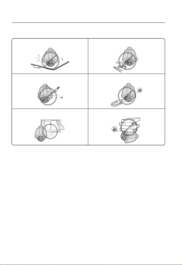
Please read the following recommend safety precautions carefully.
Do not place this apparatus on an uneven surface. Do not place this apparatus near conductive material.
Do not attempt to service this apparatus yourself. Do not install near any magnetic sources.
Do not block any ventilation openings. Do not place heavy items on the product.
User’s Manual is a guidance book for how to use the products.
y
Reference : In case of providing information for helping of product’s usages
y
Notice : If there’s any possibility to occur any damages for the goods and
human caused by not following the instruction
Ú
Please read this manual for the safety before using of goods and keep it in
the safe place.
6_ overview
This equipment has been tested and found to comply with the limits for a
Class A digital device, pursuant to part 15 of the FCC Rules. These limits are
designed to provide reasonable protection against harmful interference when
the equipment is operated in a commercial environment.
This equipment generates, uses, and can radiate radio frequency energy and,
if not installed and used in accordance with the instruction manual, may cause
harmful interference to radio communications. Operation of this equipment in a
residential area is likely to cause harmful interference in which case the user will
be required to correct the interference at his own expense.
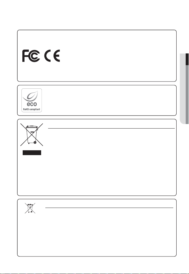
Samsung Techwin cares for the environment at all product manufacturing stages, and is
taking measures to provide customers with more environmentally friendly products.
The Eco mark represents Samsung Techwin’s devotion to creating environmentally friendly
products, and indicates that the product satisfies the EU RoHS Directive.
Correct Disposal of This Product (Waste Electrical & Electronic Equipment)
(Applicable in the European Union and other European countries with separate collection systems)
This marking on the product, accessories or literature indicates that the product and its
electronic accessories (e.g. charger, headset, USB cable) should not be disposed of with other
household waste at the end of their working life. To prevent possible harm to the environment or
human health from uncontrolled waste disposal, please separate these items from other types
of waste and recycle them responsibly to promote the sustainable reuse of material resources.
Household users should contact either the retailer where they purchased this product, or
their local government office, for details of where and how they can take these items for
environmentally safe recycling.
Business users should contact their supplier and check the terms and conditions of the
purchase contract. This product and its electronic accessories should not be mixed with other
commercial wastes for disposal.
Correct disposal of batteries in this product
(Applicable in the European Union and other European countries with separate battery return systems.)
This marking on the battery, manual or packaging indicates that the batteries in this product should
not be disposed of with other household waste at the end of their working life. Where marked, the
chemical symbols Hg, Cd or Pb indicate that the battery contains mercury, cadmium or lead above the
reference levels in EC Directive 2006/66. If batteries are not properly disposed of, these substances
can cause harm to human health or the environment.
To protect natural resources and to promote material reuse, please separate batteries from other types
of waste and recycle them through your local, free battery return system.
● OVERVIEW
English _7

overview
CONTENTS
OVERVIEW
3
INSTALLATION &
CONNECTION
17
NETWORK CONNECTION
AND SETUP
42
3 Important Safety Instructions
10 Product Features
10 Recomended PC Specifications
11 Recomended SD/SDHC Memory
Card Specifications
11 What’s Included
12 At a Glance (SNP-5200)
15 At a Glance (SNP-5200H)
19 DIP Switch Setting (SNP-5200H)
29 Installation
40 Inserting/Removing an SD
Memory Card
41 Memory Card Information
(Not Included)
42 Connecting the Camera Directly
to Local Area Networking
43 Connecting the Camera Directly
to a DHCP Based DSL/Cable
Modem
44 Connecting the Camera Directly
to a PPPoE Modem
45 Connecting the Camera to a
Broadband Router with the
PPPoE/Cable Modem
46 Buttons used in IP Installer
47 Static IP Setup
50 Dynamic IP Setup
51
Port Range Forward (Port Mapping)
Setup
53 Connecting to the Camera from a
Shared Local PC
53 Connecting to the Camera from a
Remote PC via the Internet
8_ overview

WEB VIEWER
54
54 Connecting to the Camera
55 Login
56 Installing Silverlight Runtime
58 Using the Live Screen
61 Playback
63 Playing the backup recordings
● OVERVIEW
SETUP SCREEN
64
APPENDIX
96
64 Setup
64 Audio & Video Setup
77 Network Setup
83 Event Setup
91 System Setup
96 Specification
100 Product Overview
102 Troubleshooting
104 Open Source Announcement
106 GPL/LGPL Software License
English _9

overview
PRODUCT FEATURES
HD Video Quality
•
Multi-Streaming
•
This network camera can display videos in different resolutions and qualities
simultaneously using different CODECs.
However, MPEG-4 video can not be played on a web page. Use CMS software if you want to play
M
the video on a web page.
Web Browser-based Monitoring
•
Using the Internet web browser to display the image in a local network environment.
Alarm
•
If an event occurs, the event-related video will be transferred to the email specified by the
user or saved to the SD memory, or the event signal will be sent to the Alarm Out port.
Intelligent Video Analysis
•
Analyzes the event video according to the user-specified rules to recognize the event.
ONVIF (Spec 1.01) Compliance
•
This product supports ONVIF Core Spec. 1.01.
For more information, refer to www.onvif.org.
RECOMENDED PC SPECIFICATIONS
CPU : Intel(R) Core(TM)2 2.00 GHz or higher
•
Operating System : Windows XP, VISTA, 7
•
Resolution : 1280X1024 pixels or higher
•
RAM : 1GB or higher
•
Web Browser :
•
Neither a beta test version unlike the version released in the company website nor the developer version will
be supported.
On Firefox v3.5 or higher, displaying warning message dialog may cause an error.
If connecting to IPv6 in Windows XP, it can cause some problem.
It is recommended to connect to IPv6 in Windows 7.
•
Video Memory : 128MB or higher
Mac OS
Internet Explorer 6.0 or higher
Firefox, Google Chrome, Safari
10_ overview
RECOMENDED SD/SDHC MEMORY CARD SPECIFICATIONS
2GB ~ 32GB
•
•
To ensure proper recording of video data, it is recommended you use a memory card that
supports at least read/write speed 10Mbps and Class 6.
● OVERVIEW
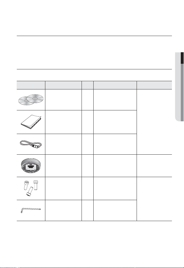
WHAT’S INCLUDED
Please check if your camera and accessories are all included in the product package.
Appearance Item Name
User Manual,
Installer S/W DVD,
CMS S/W DVD
Quantity
2
Description Model Name
Quick Guide 1
BNC cable 1
Installation base 1
Hexagon screw 3
L Wrench 1
Used to test the camera
connection to a portable display
device
If installing it indoors or in a
ceiling housing
Used for attaching the
installation base to the camera
Used for fixing the installation
base after attaching it to the
camera
SNP-5200/SNP-5200H
SNP-5200
SNP-5200H
English _11
overview
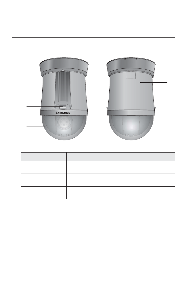
AT A GLANCE (SNP-5200)
Appearance
b
Item Description
Unlock button Used if installing the camera in the installation base.
Dome Cover Dome cover for the lens and unit protection.
b
Main unit Protect the internal PTZ mechanism from the direct sunlight.
c
c
12_ overview
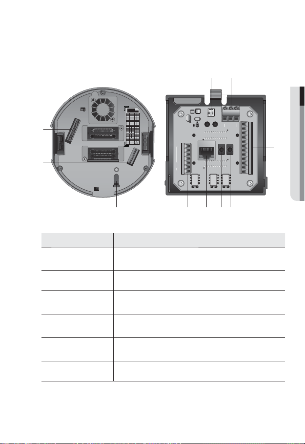
Bottom View of Installation
Base
2
SW
/0
b
Inner View of Installation Base
● OVERVIEW
ON
ON
SW1
OFF
12345678
ON
ON
SW2
OFF
123456789 121110
Protocol
2-1
2-2 2-3 2-4
STW
OFF OFF OFF OFF
OFF OFF OFF ON
Pelco-D
OFF OFF ON OFF
Pelco-P
OFF OFF ON ON
SEC
OFF ON OFF OFF
Panasonic
OFF ON OFF ON
Vicon
OFF OFFON ON
Honeywell
AD
OFF ON ON ON
GE
ON OFF OFF OFF
BOSCH
ON OFF OFF ON
Weight
2-5 2-6
Address
Baud
1-1
1
ON2,400
ON
4,800
ON OFF
1-2
2
9,600
OFF OFF
1-3
3
19,200
OFF ON
1-4
4
1-5
16
2-10
Termination
2-11
1-6
32
XOFFOFF
1-7
64
ONON
O
1-8
128
ETC
2-7
2-8 2-9 2-12
ON
422
ON
Response
AUX1
AUX2
SW1
$POUSPMMFS "VY
7JEFP0VU
1PXFS
/$
"$_7
/
$0.
/$
%%59%
39
39
59
59%
59
(/%
(/%
"$0.
$0.
"/0
/0
"9*$0.
*.0
7%$
"9*$0.
*.0
7%$
"MBSN0/"MBSN0/
/
$0.
(/%
*/
"6%*0@065"6%*0@*/
*/
(/%
*/
*/
*/*/(/%*/*/(/%$.//$$.//$
"MBSN
"9*$0.
*.0
7%$
c
Item Description
Communications
Setup Switch
ID Setup Switch Specify the camera ID.
b
Safety cable hook
c
Communications
and AUX Ports
Network
Connections
Audio Input Port Used to connect the audio input cable.
Set the transfer rate and protocols.
Cable hook that is designed for preventing an accidental fall of the dome
camera.
Used for RS-485 communications.
Network cable port.
English _13

overview
Item Description
Audio Output Port Used to connect the audio output cable.
Alarm I/O Port Used to connect the alarm I/O cable.
Power Port Used to connect the power.
Video Out Port Analog video output port. (for installation)
14_ overview
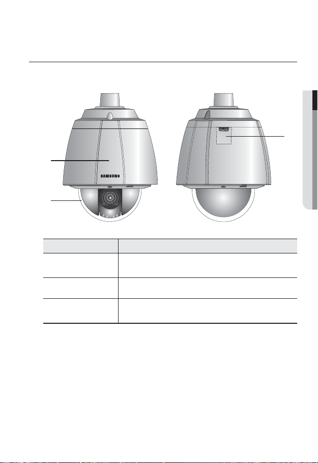
AT A GLANCE (SNP-5200H)
Appearance
b
Item Description
Main unit
Dome Cover Dome cover for the lens and unit protection.
b
Safety cable hook
c
Protects the internal PTZ mechanism from the direct sunlight, rain or
external impact.
Cable hook that is designed for preventing an accidental fall of the dome
camera.
● OVERVIEW
c
English _15
overview
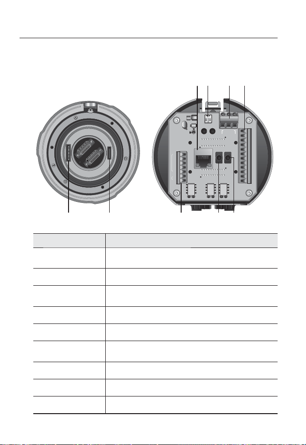
Bottom View of Installation
Base
b
Item Description
Communications
Setup Switch
ID Setup Switch Specify the camera ID.
b
Communications
c
and AUX Ports
Audio Input Port Used to connect the audio input cable.
Audio Output Port Used to connect the audio output cable.
Network
Connections
Video Out Port Analog video output port. (for installation)
Power Port Used to connect the power.
Alarm I/O Port Used to connect the alarm I/O cable.
Set the transfer rate and protocols.
Used for RS-485 communications.
Network cable port.
Inner View of Installation Base
%%59%
39
$POUSPMMFS "VY
39
59
59%
59
(/%
(/%
"$0.
$0.
"/0
/0
"9*$0.
*.0
7JEFP0VU
1PXFS
"$_7
"9*$0.
"9*$0.
*.0
7%$
7%$
"MBSN0/"MBSN0/
/$
/
$0.
/$
/
$0.
(/%
*/
"6%*0@065"6%*0@*/
*/
(/%
*/
*/
*/*/(/%*/*/(/%$.//$$.//$
"MBSN
*.0
7%$
c
16_ overview
installation & connection
❖
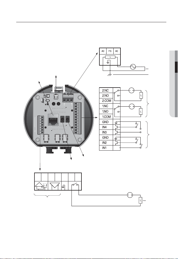
Camera Wiring Interface Board
For the camera wiring, please refer to the picture below.
Power Supply
AC24V 2.5A
● INSTALLATION & CONNECTION
Video
Output
ETHERNET
7JEFP0VU
1PXFS
"$_7
%%59%
39
$POUSPMMFS "VY
39
59
59%
59
(/%
(/%
"$0.
$0.
"/0
/0
"9*$0.
*.0
"6%*0@065"6%*0@*/
"9*$0.
*.0
"9*$0.
*.0
7%$
7%$
"MBSN0/"MBSN0/
Audio IN
Communications and AUX
RX+ RX- TX+ TX- GND COM N.O
Refer to Control Signal
Connection Diagram
7%$
/$
/
$0.
/$
/
$0.
(/%
*/
*/
(/%
*/
*/
*/*/(/%*/*/(/%$.//$$.//$
"MBSN
Audio OUT
Power Input
Ground
Alarm
Alarm output
Alarm Input
AUX Output
English _17

installation & connection
Control Signal Connection
•
RS-485 Communications
Camera
RX+
RX-
The maximum power capacity of the alarm and AUX outputs is 30VDC/2A, 125VAC/0.5A, and
J
250VAC/0.25A.
When connecting alarm input and output cables, be sure to connect one cable to each terminal
respectively.
To connect products over the camera’s capacity, please use an additional relay device.
Connecting the power connector and GND incorrectly to the NC/NO and COM ports can cause a
short circuit which may lead to fire and damage the camera.
Controller
or DVR
TXD+
TXD-
•
RS-422 Communications
Camera
RX+
RX-
TX+
TX-
Controller
or DVR
TXD+
TXD-
RXD+
RXD-
18_ installation & connection
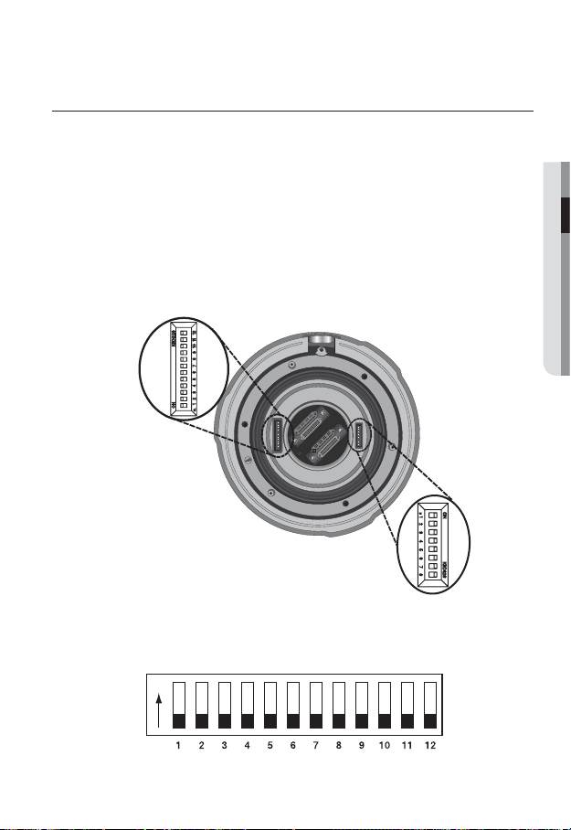
DIP SWITCH SETTING (SNP-5200H)
How to set up Protocols and ID DIP Switches
You can control various settings of the camera system using the Communication and ID
DIP switches. Before installing the product, please set up the DIP switches according to the
installation environment.
Set the switches according to your installation environment. For more detailed setup
1.
information, please refer to the chart on the next page.
The camera may malfunction if the switches are not fully turned On/Off; please
2.
double check the switches before finishing setup.
Communication Protocol DIP
Switch (SW2)
Camera ID DIP Switch (SW1)
● INSTALLATION & CONNECTION
Communication Protocol DIP Switch Settings (SW2)
ON
SW2
ON
OFF
English _19

installation & connection
SW2 Pin No. Purpose
1~4 Protocol Settings
5~6 Baud Rate Settings
7 Transfer Method (RS-485/422) Settings
8 Response Mode Settings
9 RESERVED
10~11 Termination Settings
12 RESERVED
•
Protocol Settings
Select a communication protocol for the camera.
No. Protocol SW2-#1 SW2-#2 SW2-#3 SW2-#4
1 SAMSUNG-T OFF OFF OFF OFF
2 PELCO-D OFF OFF OFF ON
3 PELCO-P OFF OFF ON OFF
4 SAMSUNG-E OFF OFF ON ON
5 Panasonic OFF ON OFF OFF
6 VICON OFF ON OFF ON
7 Honeywell OFF ON ON OFF
8 AD OFF ON ON ON
9 Reserved ON OFF OFF OFF
10 Reserved ON OFF OFF ON
11 Reserved ON OFF ON OFF
12 Reserved ON OFF ON ON
13 Reserved ON ON OFF OFF
14 Reserved ON ON OFF ON
15 Reserved ON ON ON OFF
16 Reserved ON ON ON ON
20_ installation & connection
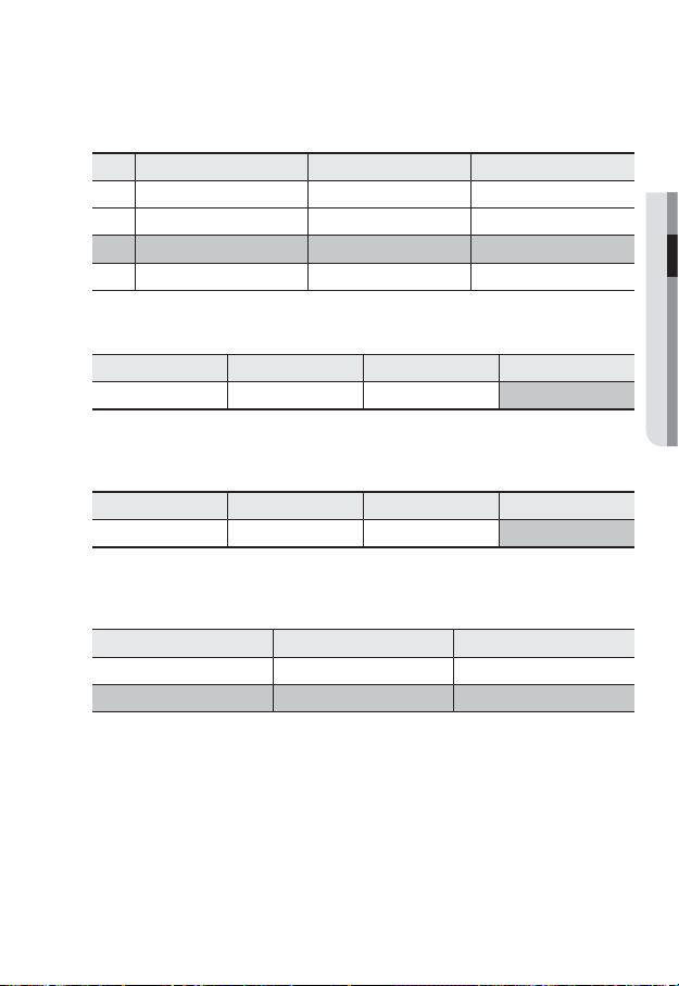
Baud Rate Settings
•
Select the transfer speed of a selected communication protocol.
No. Baud Rate (BPS) SW2-#5 SW2-#6
1 2400 ON ON
2 4800 ON OFF
3 9600 OFF OFF
4 19200 OFF ON
•
Communication Method Settings
Select a communication method for the camera.
Function ON OFF
SW2-#7 Transfer Mode Switch RS-422(4Wire) RS-485(2Wire)
•
Communication Response Settings
Select a communication response method for the camera and controller: Response or No
Response.
Function ON OFF
SW2-#8 Response Mode Switch Response No Response
•
Termination Settings
To prevent the attenuation of communication signals between the camera and controller,
the items at the end of line must be set up with the termination settings.
Camera Input Position SW2-#10 SW2-#11
Termination of Longest Path ON ON
On the Path OFF OFF
The default value is shaded in each setting table.
M
To use a third party controller with this product, please contact our After-Sales Service or
Technology Department.
● INSTALLATION & CONNECTION
English _21

installation & connection
Camera ID DIP Switch Settings (SW1)
To set up camera IDs, refer to the “Camera ID Chart” next.
ON
ON
OFF
Camera ID Chart
•
ID SW1-#1 SW1-#2 SW1-#3 SW1-#4 SW1-#5 SW1-#6 SW1-#7 SW1-#8
1 ON/OFF OFF OFF OFF OFF OFF OFF OFF
2 OFF ON OFF OFF OFF OFF OFF OFF
3 ON ON OFF OFF OFF OFF OFF OFF
4 OFF OFF ON OFF OFF OFF OFF OFF
5 ON OFF ON OFF OFF OFF OFF OFF
6 OFF ON ON OFF OFF OFF OFF OFF
7 ON ON ON OFF OFF OFF OFF OFF
8 OFF OFF OFF ON OFF OFF OFF OFF
9 ON OFF OFF ON OFF OFF OFF OFF
10 OFF ON OFF ON OFF OFF OFF OFF
11 ON ON OFF ON OFF OFF OFF OFF
12 OFF OFF ON ON OFF OFF OFF OFF
13 ON OFF ON ON OFF OFF OFF OFF
14 OFF ON ON ON OFF OFF OFF OFF
15 ON ON ON ON OFF OFF OFF OFF
16 OFF OFF OFF OFF ON OFF OFF OFF
17 ON OFF OFF OFF ON OFF OFF OFF
18 OFF ON OFF OFF ON OFF OFF OFF
19 ON ON OFF OFF ON OFF OFF OFF
20 OFF OFF ON OFF ON OFF OFF OFF
21 ON OFF ON OFF ON OFF OFF OFF
22 OFF ON ON OFF ON OFF OFF OFF
23 ON ON ON OFF ON OFF OFF OFF
24 OFF OFF OFF ON ON OFF OFF OFF
25 ON OFF OFF ON ON OFF OFF OFF
26 OFF ON OFF ON ON OFF OFF OFF
27 ON ON OFF ON ON OFF OFF OFF
28 OFF OFF ON ON ON OFF OFF OFF
SW1
22_ installation & connection

ID SW1-#1 SW1-#2 SW1-#3 SW1-#4 SW1-#5 SW1-#6 SW1-#7 SW1-#8
29 ON OFF ON ON ON OFF OFF OFF
30 OFF ON ON ON ON OFF OFF OFF
31 ON ON ON ON ON OFF OFF OFF
32 OFF OFF OFF OFF OFF ON OFF OFF
33 ON OFF OFF OFF OFF ON OFF OFF
34 OFF ON OFF OFF OFF ON OFF OFF
35 ON ON OFF OFF OFF ON OFF OFF
36 OFF OFF ON OFF OFF ON OFF OFF
37 ON OFF ON OFF OFF ON OFF OFF
38 OFF ON ON OFF OFF ON OFF OFF
39 ON ON ON OFF OFF ON OFF OFF
40 OFF OFF OFF ON OFF ON OFF OFF
41 ON OFF OFF ON OFF ON OFF OFF
42 OFF ON OFF ON OFF ON OFF OFF
43 ON ON OFF ON OFF ON OFF OFF
44 OFF OFF ON ON OFF ON OFF OFF
45 ON OFF ON ON OFF ON OFF OFF
46 OFF ON ON ON OFF ON OFF OFF
47 ON ON ON ON OFF ON OFF OFF
48 OFF OFF OFF OFF ON ON OFF OFF
49 ON OFF OFF OFF ON ON OFF OFF
50 OFF ON OFF OFF ON ON OFF OFF
51 ON ON OFF OFF ON ON OFF OFF
52 OFF OFF ON OFF ON ON OFF OFF
53 ON OFF ON OFF ON ON OFF OFF
54 OFF ON ON OFF ON ON OFF OFF
55 ON ON ON OFF ON ON OFF OFF
56 OFF OFF OFF ON ON ON OFF OFF
57 ON OFF OFF ON ON ON OFF OFF
58 OFF ON OFF ON ON ON OFF OFF
59 ON ON OFF ON ON ON OFF OFF
60 OFF OFF ON ON ON ON OFF OFF
61 ON OFF ON ON ON ON OFF OFF
62 OFF ON ON ON ON ON OFF OFF
63 ON ON ON ON ON ON OFF OFF
64 OFF OFF OFF OFF OFF OFF ON OFF
65 ON OFF OFF OFF OFF OFF ON OFF
66 OFF ON OFF OFF OFF OFF ON OFF
67 ON ON OFF OFF OFF OFF ON OFF
English _23
● INSTALLATION & CONNECTION

installation & connection
ID SW1-#1 SW1-#2 SW1-#3 SW1-#4 SW1-#5 SW1-#6 SW1-#7 SW1-#8
68 OFF OFF ON OFF OFF OFF ON OFF
69 ON OFF ON OFF OFF OFF ON OFF
70 OFF ON ON OFF OFF OFF ON OFF
71 ON ON ON OFF OFF OFF ON OFF
72 OFF OFF OFF ON OFF OFF ON OFF
73 ON OFF OFF ON OFF OFF ON OFF
74 OFF ON OFF ON OFF OFF ON OFF
75 ON ON OFF ON OFF OFF ON OFF
76 OFF OFF ON ON OFF OFF ON OFF
77 ON OFF ON ON OFF OFF ON OFF
78 OFF ON ON ON OFF OFF ON OFF
79 ON ON ON ON OFF OFF ON OFF
80 OFF OFF OFF OFF ON OFF ON OFF
81 ON OFF OFF OFF ON OFF ON OFF
82 OFF ON OFF OFF ON OFF ON OFF
83 ON ON OFF OFF ON OFF ON OFF
84 OFF OFF ON OFF ON OFF ON OFF
85 ON OFF ON OFF ON OFF ON OFF
86 OFF ON ON OFF ON OFF ON OFF
87 ON ON ON OFF ON OFF ON OFF
88 OFF OFF OFF ON ON OFF ON OFF
89 ON OFF OFF ON ON OFF ON OFF
90 OFF ON OFF ON ON OFF ON OFF
91 ON ON OFF ON ON OFF ON OFF
92 OFF OFF ON ON ON OFF ON OFF
93 ON OFF ON ON ON OFF ON OFF
94 OFF ON ON ON ON OFF ON OFF
95 ON ON ON ON ON OFF ON OFF
96 OFF OFF OFF OFF OFF ON ON OFF
97 ON OFF OFF OFF OFF ON ON OFF
98 OFF ON OFF OFF OFF ON ON OFF
99 ON ON OFF OFF OFF ON ON OFF
100 OFF OFF ON OFF OFF ON ON OFF
101 ON OFF ON OFF OFF ON ON OFF
102 OFF ON ON OFF OFF ON ON OFF
103 ON ON ON OFF OFF ON ON OFF
104 OFF OFF OFF ON OFF ON ON OFF
105 ON OFF OFF ON OFF ON ON OFF
106 OFF ON OFF ON OFF ON ON OFF
24_ installation & connection

ID SW1-#1 SW1-#2 SW1-#3 SW1-#4 SW1-#5 SW1-#6 SW1-#7 SW1-#8
107 ON ON OFF ON OFF ON ON OFF
108 OFF OFF ON ON OFF ON ON OFF
109 ON OFF ON ON OFF ON ON OFF
110 OFF ON ON ON OFF ON ON OFF
111 ON ON ON ON OFF ON ON OFF
112 OFF OFF OFF OFF ON ON ON OFF
113 ON OFF OFF OFF ON ON ON OFF
114 OFF ON OFF OFF ON ON ON OFF
115 ON ON OFF OFF ON ON ON OFF
116 OFF OFF ON OFF ON ON ON OFF
117 ON OFF ON OFF ON ON ON OFF
118 OFF ON ON OFF ON ON ON OFF
119 ON ON ON OFF ON ON ON OFF
120 OFF OFF OFF ON ON ON ON OFF
121 ON OFF OFF ON ON ON ON OFF
122 OFF ON OFF ON ON ON ON OFF
123 ON ON OFF ON ON ON ON OFF
124 OFF OFF ON ON ON ON ON OFF
125 ON OFF ON ON ON ON ON OFF
126 OFF ON ON ON ON ON ON OFF
127 ON ON ON ON ON ON ON OFF
128 OFF OFF OFF OFF OFF OFF OFF ON
129 ON OFF OFF OFF OFF OFF OFF ON
130 OFF ON OFF OFF OFF OFF OFF ON
131 ON ON OFF OFF OFF OFF OFF ON
132 OFF OFF ON OFF OFF OFF OFF ON
133 ON OFF ON OFF OFF OFF OFF ON
134 OFF ON ON OFF OFF OFF OFF ON
135 ON ON ON OFF OFF OFF OFF ON
136 OFF OFF OFF ON OFF OFF OFF ON
137 ON OFF OFF ON OFF OFF OFF ON
138 OFF ON OFF ON OFF OFF OFF ON
139 ON ON OFF ON OFF OFF OFF ON
140 OFF OFF ON ON OFF OFF OFF ON
141 ON OFF ON ON OFF OFF OFF ON
142 OFF ON ON ON OFF OFF OFF ON
143 ON ON ON ON OFF OFF OFF ON
144 OFF OFF OFF OFF ON OFF OFF ON
145 ON OFF OFF OFF ON OFF OFF ON
English _25
● INSTALLATION & CONNECTION

installation & connection
ID SW1-#1 SW1-#2 SW1-#3 SW1-#4 SW1-#5 SW1-#6 SW1-#7 SW1-#8
146 OFF ON OFF OFF ON OFF OFF ON
147 ON ON OFF OFF ON OFF OFF ON
148 OFF OFF ON OFF ON OFF OFF ON
149 ON OFF ON OFF ON OFF OFF ON
150 OFF ON ON OFF ON OFF OFF ON
151 ON ON ON OFF ON OFF OFF ON
152 OFF OFF OFF ON ON OFF OFF ON
153 ON OFF OFF ON ON OFF OFF ON
154 OFF ON OFF ON ON OFF OFF ON
155 ON ON OFF ON ON OFF OFF ON
156 OFF OFF ON ON ON OFF OFF ON
157 ON OFF ON ON ON OFF OFF ON
158 OFF ON ON ON ON OFF OFF ON
159 ON ON ON ON ON OFF OFF ON
160 OFF OFF OFF OFF OFF ON OFF ON
161 ON OFF OFF OFF OFF ON OFF ON
162 OFF ON OFF OFF OFF ON OFF ON
163 ON ON OFF OFF OFF ON OFF ON
164 OFF OFF ON OFF OFF ON OFF ON
165 ON OFF ON OFF OFF ON OFF ON
166 OFF ON ON OFF OFF ON OFF ON
167 ON ON ON OFF OFF ON OFF ON
168 OFF OFF OFF ON OFF ON OFF ON
169 ON OFF OFF ON OFF ON OFF ON
170 OFF ON OFF ON OFF ON OFF ON
171 ON ON OFF ON OFF ON OFF ON
172 OFF OFF ON ON OFF ON OFF ON
173 ON OFF ON ON OFF ON OFF ON
174 OFF ON ON ON OFF ON OFF ON
175 ON ON ON ON OFF ON OFF ON
176 OFF OFF OFF OFF ON ON OFF ON
177 ON OFF OFF OFF ON ON OFF ON
178 OFF ON OFF OFF ON ON OFF ON
179 ON ON OFF OFF ON ON OFF ON
180 OFF OFF ON OFF ON ON OFF ON
181 ON OFF ON OFF ON ON OFF ON
182 OFF ON ON OFF ON ON OFF ON
183 ON ON ON OFF ON ON OFF ON
184 OFF OFF OFF ON ON ON OFF ON
26_ installation & connection

ID SW1-#1 SW1-#2 SW1-#3 SW1-#4 SW1-#5 SW1-#6 SW1-#7 SW1-#8
185 ON OFF OFF ON ON ON OFF ON
186 OFF ON OFF ON ON ON OFF ON
187 ON ON OFF ON ON ON OFF ON
188 OFF OFF ON ON ON ON OFF ON
189 ON OFF ON ON ON ON OFF ON
190 OFF ON ON ON ON ON OFF ON
191 ON ON ON ON ON ON OFF ON
192 OFF OFF OFF OFF OFF OFF ON ON
193 ON OFF OFF OFF OFF OFF ON ON
194 OFF ON OFF OFF OFF OFF ON ON
195 ON ON OFF OFF OFF OFF ON ON
196 OFF OFF ON OFF OFF OFF ON ON
197 ON OFF ON OFF OFF OFF ON ON
198 OFF ON ON OFF OFF OFF ON ON
199 ON ON ON OFF OFF OFF ON ON
200 OFF OFF OFF ON OFF OFF ON ON
201 ON OFF OFF ON OFF OFF ON ON
202 OFF ON OFF ON OFF OFF ON ON
203 ON ON OFF ON OFF OFF ON ON
204 OFF OFF ON ON OFF OFF ON ON
205 ON OFF ON ON OFF OFF ON ON
206 OFF ON ON ON OFF OFF ON ON
207 ON ON ON ON OFF OFF ON ON
208 OFF OFF OFF OFF ON OFF ON ON
209 ON OFF OFF OFF ON OFF ON ON
210 OFF ON OFF OFF ON OFF ON ON
211 ON ON OFF OFF ON OFF ON ON
212 OFF OFF ON OFF ON OFF ON ON
213 ON OFF ON OFF ON OFF ON ON
214 OFF ON ON OFF ON OFF ON ON
215 ON ON ON OFF ON OFF ON ON
216 OFF OFF OFF ON ON OFF ON ON
217 ON OFF OFF ON ON OFF ON ON
218 OFF ON OFF ON ON OFF ON ON
219 ON ON OFF ON ON OFF ON ON
220 OFF OFF ON ON ON OFF ON ON
221 ON OFF ON ON ON OFF ON ON
222 OFF ON ON ON ON OFF ON ON
● INSTALLATION & CONNECTION
English _27

installation & connection
ID SW1-#1 SW1-#2 SW1-#3 SW1-#4 SW1-#5 SW1-#6 SW1-#7 SW1-#8
223 ON ON ON ON ON OFF ON ON
224 OFF OFF OFF OFF OFF ON ON ON
225 ON OFF OFF OFF OFF ON ON ON
226 OFF ON OFF OFF OFF ON ON ON
227 ON ON OFF OFF OFF ON ON ON
228 OFF OFF ON OFF OFF ON ON ON
229 ON OFF ON OFF OFF ON ON ON
230 OFF ON ON OFF OFF ON ON ON
231 ON ON ON OFF OFF ON ON ON
232 OFF OFF OFF ON OFF ON ON ON
233 ON OFF OFF ON OFF ON ON ON
234 OFF ON OFF ON OFF ON ON ON
235 ON ON OFF ON OFF ON ON ON
236 OFF OFF ON ON OFF ON ON ON
237 ON OFF ON ON OFF ON ON ON
238 OFF ON ON ON OFF ON ON ON
239 ON ON ON ON OFF ON ON ON
240 OFF OFF OFF OFF ON ON ON ON
241 ON OFF OFF OFF ON ON ON ON
242 OFF ON OFF OFF ON ON ON ON
243 ON ON OFF OFF ON ON ON ON
244 OFF OFF ON OFF ON ON ON ON
245 ON OFF ON OFF ON ON ON ON
246 OFF ON ON OFF ON ON ON ON
247 ON ON ON OFF ON ON ON ON
248 OFF OFF OFF ON ON ON ON ON
249 ON OFF OFF ON ON ON ON ON
250 OFF ON OFF ON ON ON ON ON
251 ON ON OFF ON ON ON ON ON
252 OFF OFF ON ON ON ON ON ON
253 ON OFF ON ON ON ON ON ON
254 OFF ON ON ON ON ON ON ON
255 ON ON ON ON ON ON ON ON
28_ installation & connection
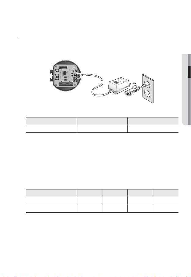
INSTALLATION
Preparing Adapter and Cable
Plug the power adapter into a power outlet.
$POUSPMMFS "VY
$0.
(/%
39
39
59
59
/0
%%59%
59%
(/%
"$0."/0
"9*$0.
*.0
7%$
7JEFP0VU
"9*$0.
*.0
7%$
"MBSN0/"MBSN0/
"9*$0.
"$_7
"6%*0@065"6%*0@*/
*.0
1PXFS
7%$
*/*/(/%*/*/(/%$.//$$.//$
"MBSN
$0.
$0.
/$
/$
(/%
(/%
/
/
*/
*/
*/
*/
Check out the rated voltage and current before making connections.
Rated Power Allowable Input Voltage Current Consumption
AC 24V AC 22V ~ 26V 2.5 A
SNP-5200 : If hPoE and AC 24V are both applied, this camera will get supplied with power from
J
hPoE.
SNP-5200H
If hPoE and AC 24V are both applied in heater operation mode, the heater will be powered by
-
AC 24V and the other devices will get supplied with power from hPoE.
If hPoE and AC 24V are both applied with heater turned off, this camera will get supplied with
-
power from hPoE.
Electrical Resistance of Copper Wire at [20°C (68°F)]
Copper Wire Gauge (AWG) #24(0.22mm2) #22(0.33mm2) #20(0.52mm2) #18(0.83mm2)
Resistance (Ω/m) 0.078 0.050 0.030 0.018
Drop Voltage (V/m) 0.028 0.018 0.011 0.06
As shown in the table above, you may encounter a voltage-sag depending on the wire length.
If you use an excessively long wire for camera connection, the camera may not work properly.
Camera Operating Voltage: AC 24V±10%
-
Voltage drop measurements on the chart above may vary depending on the type and manufacture of
-
the copper cable.
● INSTALLATION & CONNECTION
English _29
installation & connection
Communications Cable
For the camera to communicate with the controller, a RS-485/422 communications line is
required.
A 30m or shorter length is recommended for the connection.
J
The communication cable is not enclosed with the camera.
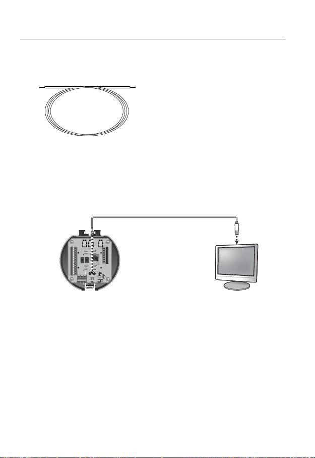
Connecting the installation monitor
Connect the cable to the camera’s rear video output terminal and the installation monitor's
video input terminal.
"MBSN0/"MBSN0/
"9*$0.
*.0
7%$
"9*$0.
*.0
7%$
"9*$0.
*.0
7%$
"MBSN
*/*/(/%*/*/(/%$.//$$.//$
*/
*/
(/%
*/
*/
(/%
$0.
/
/$
$0.
/
/$
The wiring varies depending on your monitor type and peripheral devices; please refer to the user manual
for each device.
Please make sure the monitor and camera are turned off when connecting them.
You can set the video output type to either NTSC or PAL. (page 66)
/0
"/0
$0.
"$0.
(/%
(/%
59
59%
"6%*0@065"6%*0@*/
59
39
$POUSPMMFS "VY
39
%%59%
"$_7
1PXFS
7JEFP0VU
Monitor
This product is a network camera that transfers video over a network; the video output terminal is
J
used to set the imaging range of the camera at installation.
Using the terminal for monitoring purposes may cause problems such as degradation in video
quality.
30_ installation & connection
 Loading...