


 Loading...
Blu-ray Disc Player
BD-E5300
Application BD-E5300 / BD-EM53
Models
Application Area EN, PE, PR, RU, SH, SJ, SQ, SW, TK, UM,
XA, XD, XE, XL, XM, XN, XP, XS, XT, XU,
XV, XY, XZ, ZA, ZB, ZC, ZD, ZF, ZK, ZN,
ZS, ZW, ZX
SERVICEMANUAL
Blu-Ray Disc Player |
|
Contents |
1. Precautions
2. Product Specifications
3. Disassembly and Reassembly
4. Troubleshooting
5. PCB Diagrams
6. Schematic Diagrams
Refer to the service manual in the GSPN (see the rear cover) for more information.

Contents
Contents
1. |
Precautions ...................................................................................................................................... |
|
1 |
− |
1 |
|
|
1.1. |
Safety Precautions ................................................................................................................... |
1 |
− |
1 |
|
|
1.2. |
Servicing Precautions ............................................................................................................... |
1 |
− |
3 |
|
|
|
1.2.1. |
General Servicing Precautions ....................................................................................... |
1 |
− |
3 |
|
|
1.2.2. |
Insulation Checking Procedure....................................................................................... |
1 |
− |
3 |
|
1.3. |
ESD Precautions...................................................................................................................... |
1 |
− |
4 |
|
|
1.4. Handling the optical pick-up ...................................................................................................... |
1 |
− |
5 |
||
2. |
Product Specifications........................................................................................................................ |
2 |
− |
1 |
||
|
2.1. |
Product Specification................................................................................................................ |
2 |
− |
1 |
|
|
|
2.1.1. |
Player Features ........................................................................................................... |
2 |
− |
1 |
|
|
2.1.2. |
Blu-ray Disc Features................................................................................................... |
2 |
− |
2 |
|
|
2.1.3. Disc Types and Contents that can be played...................................................................... |
2 |
− |
3 |
|
|
|
2.1.4. Logos of Discs that can be played................................................................................... |
2 |
− |
4 |
|
|
|
2.1.5. Disc types that cannot be played..................................................................................... |
2 |
− |
4 |
|
|
|
2.1.6. |
Region code ............................................................................................................... |
2 |
− |
4 |
|
|
2.1.7. |
Blu-ray Disc Compatibility............................................................................................ |
2 |
− |
6 |
|
|
2.1.8. |
Supported Formats....................................................................................................... |
2 |
− |
6 |
|
2.2. |
Chassis Product Specification..................................................................................................... |
2 |
− |
8 |
|
|
2.3. |
Option Product Specification...................................................................................................... |
2 |
− 10 |
||
3. |
Disassembly and Reassembly .............................................................................................................. |
3 |
− |
1 |
||
|
3.1. |
Cabinet and PCB ..................................................................................................................... |
3 |
− |
1 |
|
|
|
3.1.1. |
Top Cabinet Removal................................................................................................... |
3 |
− |
2 |
|
|
3.1.2. |
Assy Front-Cabinet Removal......................................................................................... |
3 |
− |
3 |
|
|
3.1.3. |
Assy Deck Removal..................................................................................................... |
3 |
− |
4 |
|
|
3.1.4. |
SMPS PCB Removal.................................................................................................... |
3 |
− |
5 |
|
|
3.1.5. |
Main PCB Removal..................................................................................................... |
3 |
− |
6 |
|
3.2. |
PCB Location ......................................................................................................................... |
3 |
− |
7 |
|
4. |
Troubleshooting................................................................................................................................ |
4 |
− |
1 |
||
|
4.1. |
Troubleshooting ...................................................................................................................... |
4 |
− |
1 |
|
|
4.2. |
Software Update...................................................................................................................... |
4 |
− 16 |
||
|
|
4.2.1. |
Upgrade..................................................................................................................... |
4 |
− 16 |
|
5. |
PCB Diagrams.................................................................................................................................. |
|
5 |
− |
1 |
|
|
5.1. |
Wiring Diagram....................................................................................................................... |
5 |
− |
1 |
|
|
5.2. |
Main PCB .............................................................................................................................. |
5 |
− |
2 |
|
|
5.3. |
S.M.P.S PCB........................................................................................................................... |
5 |
− |
4 |
|
6. |
Schematic Diagrams .......................................................................................................................... |
6 |
− |
1 |
||
|
6.1. |
All Block Diagram................................................................................................................... |
6 |
− |
2 |
|
|
6.2. |
Power.................................................................................................................................... |
|
6 |
− |
3 |
i |
Copyright© 1995-2011 SAMSUNG. All rights reserved. |

Contents
|
6.2.1. About S.M.P.S (Ringing Choke Converter Method)............................................................ |
6 |
− |
3 |
|
6.2.2. Circuit descripcotion [FLY-Back RCC(Ringing Choke Converter)] Control ............................ |
6 |
− |
3 |
|
6.2.3. Internal Block Diagram (Internal Block Diagram of S.M.P.S Circuit) .................................... |
6 |
− |
5 |
6.3. |
S.M.P.S (S.M.P.S PCB)............................................................................................................. |
6 |
− |
6 |
6.4. |
HDMI (Main PCB) .................................................................................................................. |
6 |
− |
7 |
6.5. |
NAND Flash (Main PCB) ......................................................................................................... |
6 |
− |
8 |
6.6. |
DDR3-1333 (Main PCB)........................................................................................................... |
6 |
− |
9 |
6.7. |
GPIO,BOOT STRAP,UART (Main PCB)..................................................................................... |
6 |
− 10 |
|
6.8. |
7631 POWER,DECOUPLING (Main PCB).................................................................................. |
6 |
− 11 |
|
6.9. |
DC-DC Power (Main PCB) ....................................................................................................... |
6 |
− 12 |
|
6.10. |
Front Micom (Main PCB) ......................................................................................................... |
6 |
− 13 |
|
6.11. |
F_E OPU Connection (Main PCB).............................................................................................. |
6 |
− 14 |
|
6.12. |
F_E Motor Drive (Main PCB) .................................................................................................... |
6 |
− 15 |
|
6.13. |
Ethernet, USB(Main PCB)......................................................................................................... |
6 |
− 16 |
|
6.14. |
Audio_Video (Main PCB) ......................................................................................................... |
6 |
− 17 |
|
Copyright© 1995-2011 SAMSUNG. All rights reserved. |
ii |
1. Precautions
1. Precautions
1.1. Safety Precautions
1)Before returning an instrument to the customer, always make a safety check of the entire instrument, including, but not limited to, the following items:
a)Be sure that no built-in protective devices are defective or have been defeated during servicing
i)Protective shields are provided to protect both the technician and the customer. Correctly replace all missing protective shields, including any removed for servicing convenience.
ii)When reinstalling the chassis and/or other assembly in the cabinet, be sure to put back in place all protective devices, including, but not limited to, nonmetallic control knobs, insulating fish papers, adjustment and compartment covers/shields, and isolation resistor/capacitor networks. Do not operate this instrument or permit it to be operated without all protective devices correctly installed and functioning.
b)Be sure that there are no cabinet openings through which adults or children might be able to insert their fingers and contact a hazardous voltage. Such openings include, but are not limited to, excessively wide cabinet ventilation slots, and an improperly fitted and/or incorrectly secured cabinet back cover.
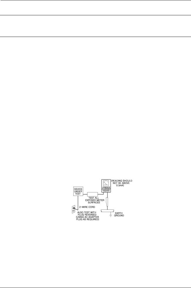
c)Leakage Current Hot Check — With the instrument completely reassembled, plug the AC line cord directly into a 230V(220V ~ 240V) AC outlet. (Do not use an isolation transformer during this test.)
Use a leakage current tester or a metering system that complies with American National Standard Institute (ANSI) C101.1 Leakage Current for Appliances and Underwriters Laboratories (UL) 1270 (40.7). With the instrument’s AC switch first in the ON position and then in the OFF position, measure from a known earth ground (metal water pipe, conduit, etc.) to all exposed metal parts of the instrument (antennas, handle brackets, metal cabinets, screwheads, metallic overlays, control shafts, etc.), especially any exposed metal parts that offer an electrical return path to the chassis.
Any current measured must not exceed 0.5mA.
Reverse the instrument power cord plug in the outlet and repeat the test. See
Any measurements not within the limits specified herein indicate a potential shock hazard that must be eliminated before returning the instrument to the customer.
Figure1.1 AC Leakage Test
1-1 |
Copyright© 1995-2011 SAMSUNG. All rights reserved. |

1. Precautions
d)Insulation Resistance Test Cold Check — (1) Unplug the power supply cord and connect a jumper wire between the two prongs of the plug. (2) Turn on the power switch of the instrument. (3) Measure the resistance with an ohmmeter between the jumpered AC plug and all exposed metallic cabinet parts on the instrument, such as screwheads, antenna, control shafts, handle brackets, etc. When an exposed metallic part has a return path to the
chassis, the reading should be between 1 and 5.2 megohm. When there is no return path to the chassis, the reading must be infinite. If the reading is not within the limits specified, there is the possibility of a shock hazard, and the instrument must be repaired and rechecked before it is returned to the customer. See
2)Read and comply with all caution and safety related notes on or inside the cabinet, or on the chassis.
3)Design Alteration Warning — Do not alter or add to the mechanical or electrical design of this instrument.
Design alterations and additions, including but not limited to, circuit modifications and the addition of items such as auxiliary audio output connections, might alter the safety characteristics of this instrument and create a hazard to the user. Any design alterations or additions will make you, the servicer, responsible for personal injury or property damage resulting therefrom.
4)Observe original lead dress. Take extra care to assure correct lead dress in the following areas:
(1)near sharp edges, (2) near thermally hot parts (be sure that leads and components do not touch thermally hot parts),
(3)the AC supply, (4) high voltage, and (5) antenna wiring. Always inspect in all areas for pinched, out-of-place, or frayed wiring, Do not change spacing between a component and the printed-circuit board. Check the AC power cord for damage.
5)Components, parts, and/or wiring that appear to have overheated or that are otherwise damaged should be replaced with components, parts and/or wiring that meet original specifications.
Additionally, determine the cause of overheating and/or damage and, if necessary, take corrective action to remove any potential safety hazard.
6)Product Safety Notice — Some electrical and mechanical parts have special safety-related characteristics which are often not evident from visual inspection, nor can the protection they give necessarily be obtained by replacing them with components rated for higher voltage, wattage, etc. Parts that have special safety characteristics are identified by shading,
an (  ) schematics and parts lists. Use of a substitute replacement that does not have the same safety characteristics as the recommended replacement part might create shock, fire and/or other hazards. Product safety is under review
continuously and new instructions are issued whenever appropriate.
Copyright© 1995-2011 SAMSUNG. All rights reserved. |
1-2 |

1. Precautions
1.2. Servicing Precautions
 CAUTION
Before servicing units covered by this service manual and its supplements, read and follow the Safety Precautions section of this manual.
 NOTE
NOTE
If unforeseen circumstances create conflict between the following servicing precautions and any of the safety precautions, always follow the safety precautions. Remember: Safety First.
1.2.1. General Servicing Precautions
1)a. Always unplug the instrument’s AC powercord from the AC power source before (1) removing or reinstalling any component, circuit board, module or any other instrument assembly, (2) disconnecting any instrument electrical plug or other electrical connection, (3) connecting a test substitute in parallel with an electrolytic capacitor in the instrument.
b.Do not damage any plug/socket B+ voltage interlocks with which instruments covered by this service manual might be equipped.
c.Do not apply AC power to this instrument and or any of its electrical assemblies unless all solid-state device heat sinks are correctly installed.
d.Always connect a test instrument’s ground lead to the instrument chassis ground before connecting the test instrument positive lead. Always remove the test instrument ground lead last.
 NOTE
NOTE
Refer to the Safety Precautions section ground lead last.
2)The service precautions are indicated or printed on the cabinet, chassis or components. When servicing, follow the printed or indicated service precautions and service materials.
3)The components used in the unit have a specified flame resistance and dielectric strength. When replacing components, use components which have the same. Components identified by shading, in the circuit diagram are important for safety or for the characteristics of the unit. Always replace them with the exact replacement components.
4)An insulation tube or tape is sometimes used and some components are raised above the printed wiring board for safety. The internal wiring is sometimes clamped to prevent contact with heating components. Install such elements as they were.
5)After servicing, always check that the removed screws, components, and wiring have been installed correctly and that the portion around the serviced part has not been damaged and so on.
Further, check the insulation between the blades of the attachment plug and accessible conductive parts.
1.2.2. Insulation Checking Procedure
Disconnect the attachment plug from the AC outlet and turn the power ON. Connect the insulation resistance meter (500V) to the blades of the attachment plug. The insulation resistance between each blade of the attachment plug and accessible conductive parts(see note) should be more than 1 Megohm.
 NOTE
NOTE
Accessible conductive parts include metal panels, input terminals, earphone jacks, etc.
1-3 |
Copyright© 1995-2011 SAMSUNG. All rights reserved. |

1. Precautions
1.3. ESD Precautions
Electrostatically Sensitive Devices (ESD)
Some semiconductor (solid state) devices can be damaged easily by static electricity.
Such components commonly are called Electrostatically Sensitive Devices(ESD). Examples of typical ESD devices are integrated circuits and some field-effect transistors and semiconductor chip components. The following techniques should be used to help reduce the incidence of component damage caused by static electricity.
1)Immediately before handling any semiconductor component or semiconductor-equipped assembly, drain off any electrostatic charge on your body by touching a known earth ground. Alternatively, obtain and wear a commercially available discharging wrist strap device, which should be removed for potential shock reasons prior to applying power to the unit under test.
2)After removing an electrical assembly equipped with ESD devices, place the assembly on a conductive surface such as aluminum foil, to prevent electrostatic charge buildup or exposure of the assembly.
3)Use only a grounded-tip soldering iron to solder or unsolder ESD devices.
4)Use only an anti-static solder removal devices. Some solder removal devices not classified as “anti-static” can generate electrical charges sufficient to damage ESD devices.
5)Do not use freon-propelled chemicals. These can generate electrical charges sufficient to damage ESD devices.
6)Do not remove a replacement ESD device from its protective package until immediately before installing it. (Most replacement ESD devices are packaged with leads electrically shorted together by conductive foam, aluminum foil or comparable conductive materials).
7)Immediately before removing the protective materials from the leads of a replacement ESD device, touch the protective material to the chassis or circuit assembly into which the device will be installed.
 CAUTION
Be sure no power is applied to the chassis or circuit, and observe all other safety precautions.
8)Minimize body motions when handling unpackaged replacement ESD devices.
(Otherwise harmless motions such as the brushing together of your clothes fabric or the lifting of your foot from a carpeted floor can generate static electricity sufficient to damage an ESD device).
Copyright© 1995-2011 SAMSUNG. All rights reserved. |
1-4 |
1. Precautions
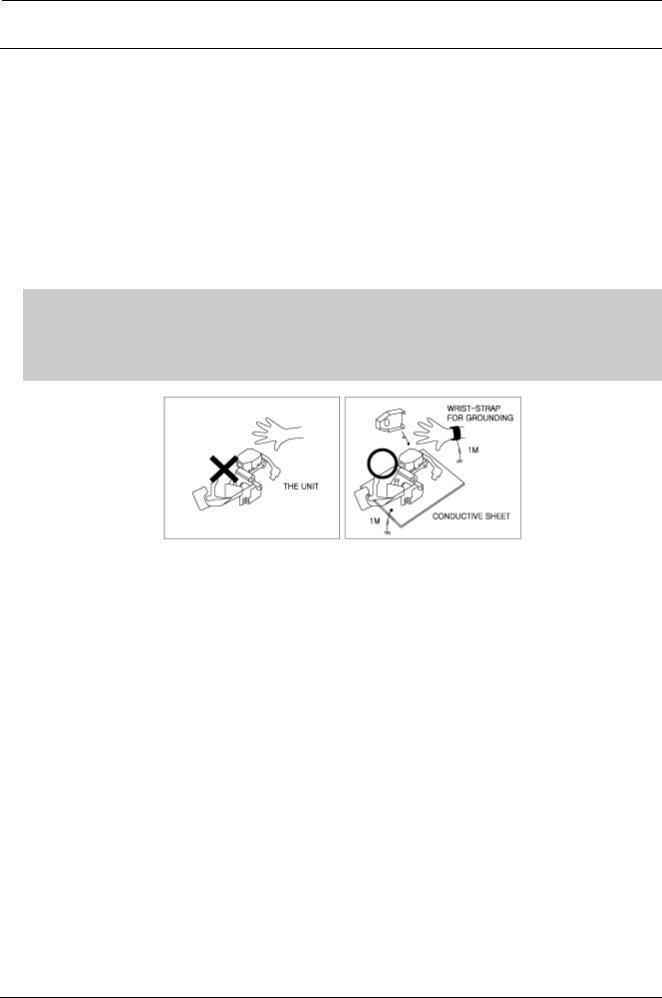
1.4. Handling the optical pick-up
The laser diode in the optical pick up may suffer electrostatic breakdown because of potential static electricity from clothing and your body.
The following method is recommended.
1)Place a conductive sheet on the work bench (The black sheet used for wrapping repair parts.)
2)Place the set on the conductive sheet so that the chassis is grounded to the sheet.
3)Place your hands on the conductive sheet(This gives them the same ground as the sheet.)
4)Remove the optical pick up block
5)Perform work on top of the conductive sheet. Be careful to let your clothes or any other static sources touch the unit.
 NOTE
NOTE
•Be sure to put on a wrist strap grounded to the sheet.
•Be sure to lay a conductive sheet, that is grounded to the table, made of copper.
Fig.1-3
6)Short the short terminal on the PCB, which is inside the Pick-Up ASS’Y, before replacing the PickUp. (The short terminal is shorted when the PickUp Ass’y is being lifted or moved.)
7)After replacing the Pick-up, open the short terminal on the PCB.
1-5 |
Copyright© 1995-2011 SAMSUNG. All rights reserved. |
2. Product Specifications
2. Product Specifications
2.1. Product Specification
2.1.1. Player Features
•Supports a Variety of Disc Types
-Blu-ray (BD-ROM, BD-RE, BD-R), DVD Video, DVD-RW/-R (V mode and finalized only) discs and Audio CD.
-CD-RW/CD-R, DVD-RW/-R and USB storage device content such as MP3, JPEG and DivX files.
•HDMI (High Definition Multimedia Interface)
HDMI reduces picture noise by allowing a pure digital video/audio signal path from the player to your TV.
Copyright© 1995-2011 SAMSUNG. All rights reserved. |
2-1 |
2. Product Specifications
2.1.2. Blu-ray Disc Features
Blu-ray Discs can store 25 GB (single layer) or 50 GB (dual layer) on a single sided disc - about 5 to 10 times the capacity of a DVD. Blu-ray Discs also support the highest quality HD video available in the industry (up to 1920 x 1080 at 40 Mbit/sec) –Large capacity means no compromise on video quality. Furthermore, a Blu-ray Disc has the same familiar size and look as DVD.
 NOTE
NOTE
The following Blu-ray Disc features are disc dependant and will vary.
Appearance and navigation of features will also vary from disc to disc.
Not all discs will have the features described below.
•Video highlights
The BD-ROM format for movie distribution supports three highly advanced video codecs, including AVC, VC-1, and MPEG-2.
HD video resolutions are also available:
-1920 x 1080 HD
-1280 x 720 HD
•For High-Definition Playback
To view high-definition contents in BD discs, an HDTV (High Definition Television) is required. Some discs may require using the player's HDMI OUT to view high-Definition content. The ability to view high-Definition content on BD discs may be limited depending on the resolution of your TV.
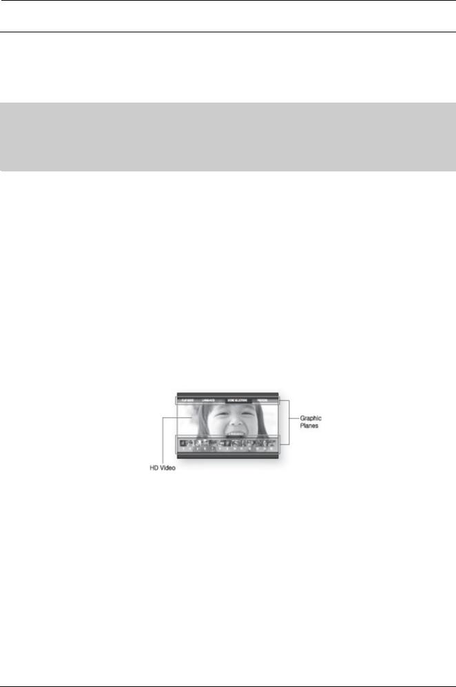
•Graphic planes
Two individual, full HD resolution (1920x1080) video layers are available on top of the HD video layer.
One layer is assigned to video-related graphics (like subtitles), and the other layer is assigned to interactive elements, such as buttons or menus. Various wipes, fades and scroll effects may be available on both layers.
•Menu graphics
Support 256 full color resolution graphics and animation, thereby greatly surpassing the capabilities of DVDVideo. Unlike DVD, Menus can be accessed during video playback.
•Menu sounds
When you highlight or select a menu option on a Blu-ray disc, sounds can be heard such as button clicks or a voice over explaining the highlighted menu choice.
•Multi-page/PopUp Menus
With DVD-Video, playback is interrupted each time a new menu screen is accessed. Due to Blu-ray Disc's ability to preload data from the disc without interrupting playback, a menu may consist of several pages.
You can browse through the menu pages or select different menu paths, while the audio and video remain playing in the background.
•Interactivity
Certain Blu-ray Discs may contain Animated menus and Trivia games.
2-2 |
Copyright© 1995-2011 SAMSUNG. All rights reserved. |
2. Product Specifications
•User Browsable Slideshows
With Blu-ray Discs, you can browse through various still pictures while the audio remains playing.
•Subtitles
Depending on what is contained on the Blu-ray Disc, you may be able to select different font styles, sizes and colors for the subtitles, Subtitles may also be animated, scrolled or faded in and out.
•BD-LIVE
You can use a Blu-ray Disc supporting BD-LIVE through network connection to enjoy various contents provided by the disc manufacturer.
2.1.3. Disc Types and Contents that can be played
 NOTE
NOTE
•The player may not play certain CD-RW/-R and DVD-R because of the disc type or recording conditions.
•If a DVD-RW/-R has not been recorded properly in DVD video format, it will not be playable.
•Your player will not play content that has been recorded on a DVD-R at a bit-rate that exceeds 10 Mbps.
•Your player will not play content that has been recorded on a BD-R or USB device at a bit rate that exceeds 25Mbps.
•Playback may not work for some types of discs, or when you use specific operations, such as angle change and aspect ratio adjustment. Information about the discs is written in detail on the disc box. Please refer to this if necessary.
•When you play a BD-J title, loading may take longer than a normal title or some functions may perform slowly.
Copyright© 1995-2011 SAMSUNG. All rights reserved. |
2-3 |
2. Product Specifications
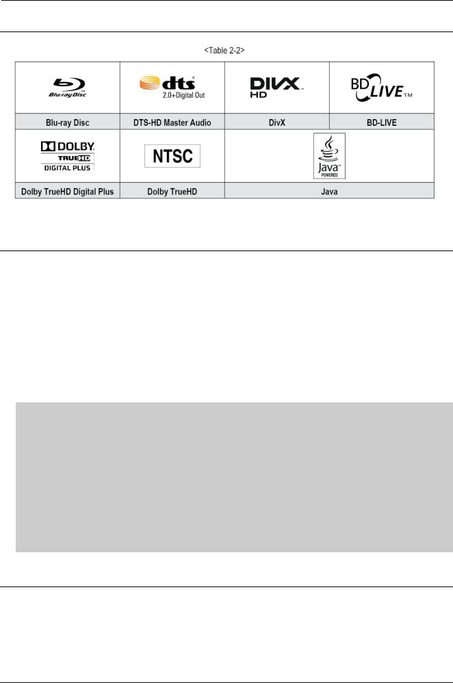
2.1.4. Logos of Discs that can be played
2.1.5. Disc types that cannot be played
•HD DVD
•DVD-RAM
•DVD-RW(VR mode)
•3.9 GB DVD-R for Authoring.
•DVD-ROM/PD/MV, etc
•Super Audio CD (except CD layer)
•CVD/CD-ROM/CDV/CD-G/CD-I/LD (CD-Gs play audio only, not graphics.)
 NOTE
NOTE
-This player may not respond to all operating commands because some Blu-ray Disc, DVD, and CD allow specific or limited operation and provide only certain features during playback. Please note that this is not a defect in the player.
-Samsung cannot guarantee that this player will play every disc bearing the Blu-ray Disc, DVD or CD logo because disc formats evolve, and problems and errors may occur during the creation of Blu-ray Disc, DVD, and CD software and/or the manufacture of discs.
Information about the discs is written in detail on the disc box. Please refer to this if necessary.
-Please contact the SAMSUNG Customer Care Center at 1-800-726-7864 if you have questions or encounter difficulty when playing Blu-ray Disc, DVD, or CD in this player. Also, refer to rest of this user manual for additional information on playback restrictions.
-Some commercial discs and DVDs purchased outside your region may not play on this player.
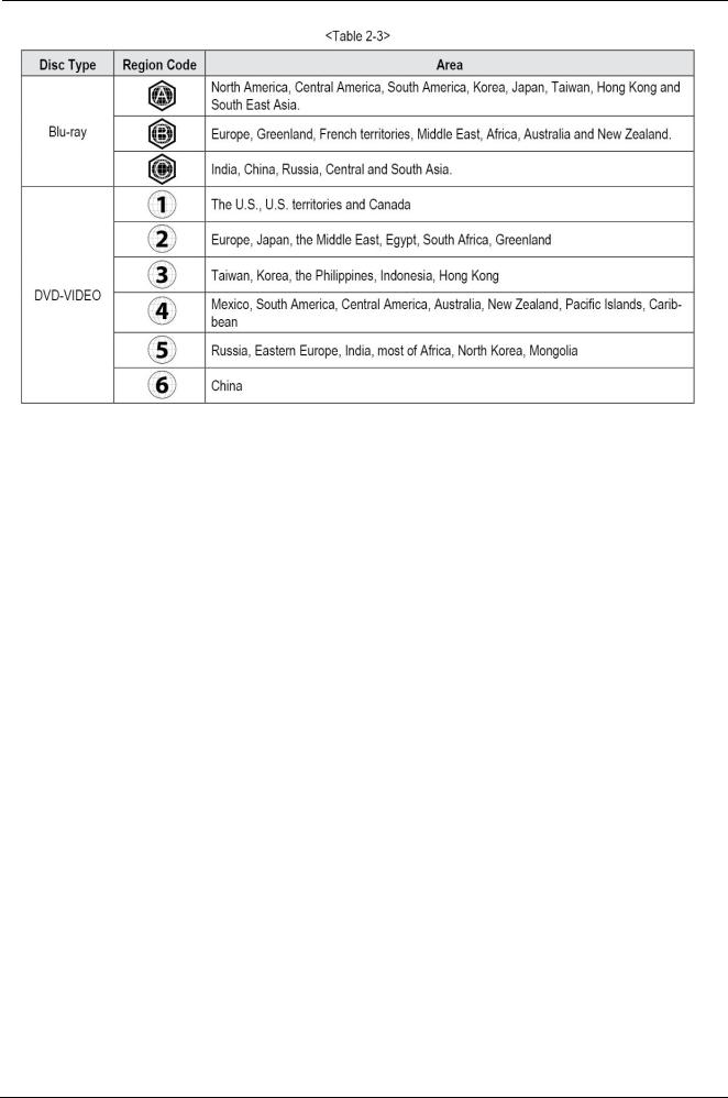
2.1.6. Region code
Both the product and the discs are coded by region. These regional codes must match in order to play the disc. If the codes do not match, the disc will not play. The Region Number for this product is described on the rear panel of the product.
2-4 |
Copyright© 1995-2011 SAMSUNG. All rights reserved. |
2. Product Specifications
Copyright© 1995-2011 SAMSUNG. All rights reserved. |
2-5 |
2. Product Specifications
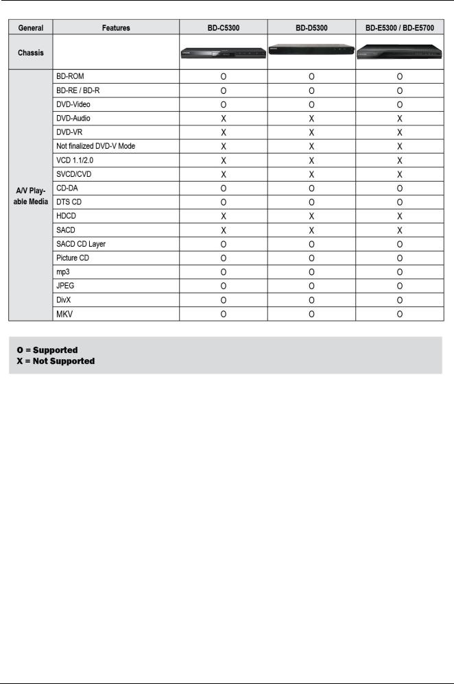
2.1.7. Blu-ray Disc Compatibility
Blu-ray Disc is a new and evolving format. Accordingly, disc compatibility issues are possible. Not all discs are compatible and not every disc will play back. For additional information, refer to the Compliance and Compatibility Notice section of this Manual. If you encounter compatibility problems, please contact the SAMSUNG customer care center. This Samsung Blu-ray disc player supports only the BDROM Profile 2 (a.k.a. BD-LIVE). If you want to play later version discs, you may need to update player's firmware. Please refer to http://www.samsung.com or contact SAMSUNG customer
care center at 1-800 SAMSUNG.
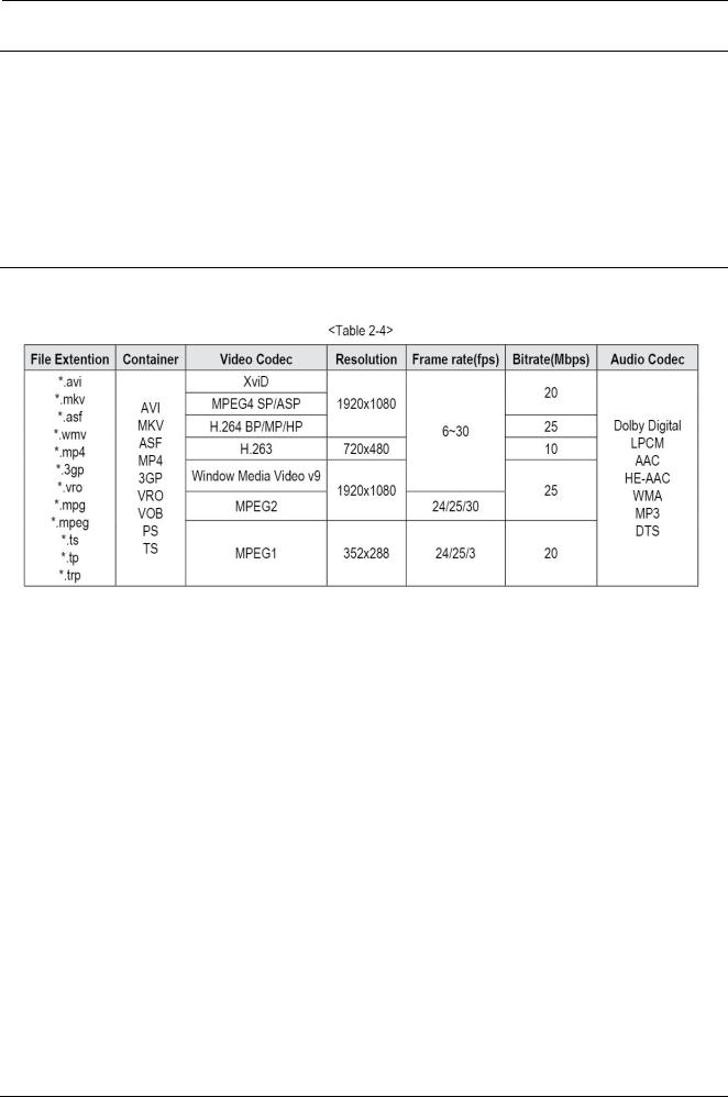
2.1.8. Supported Formats
Video File Support
•Limitations
-Even when the file is encoded by a supported codec listed above, a file might not be played if its content has a problem.
-Normal playback is not guaranteed if the file’s container information is wrong or the file itself is corrupted.
-Files having higher Bitrate/frame rate than standard may stutter when played back.
-Seek (skip) function is not available if the file’s index table is damaged.
-When you playback a file remotely through a network connection, video playback may stutter depending on the network speed.
-Some USB/Digital camera devices may not be compatible with the player.
•Video decoder
-Supports up to H.264 Level 4.1
-Does not support GMC 2 or higher
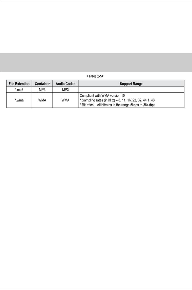
•Audio decoder
-Supports WMA 7, 8, 9 and STD
-Does not support WMA 9 PRO multi-channel or lossless audio if number of channels is more than 2.
-Does not support WMA sampling rate of 22050Hz mono.
•Audio decoder
-Supports WMA 7, 8, 9 and STD
-Does not support WMA 9 PRO multi-channel or lossless audio if number of channels is more than 2.
-Does not support WMA sampling rate of 22050Hz mono.
2-6 |
Copyright© 1995-2011 SAMSUNG. All rights reserved. |
2. Product Specifications
•Comments
-Xvid, MPEG4 : Supports up to GMC 1-Warping Point.
-H.264 : Supports up to BP/MP/HP Level 4.1.
-H.263 : Supports up to Profile3, restricted up to SD resolution.
-WMV : Supports V9, VC1 SP/MP/AP L3.
-MPEG1 : Does not support D-picture.
-MPEG2 : Supports up to Hight Profile High Level.
 NOTE
NOTE
•Some MKV and MP4 format discs may not play, depending on their video resolution and frame rate.
Copyright© 1995-2011 SAMSUNG. All rights reserved. |
2-7 |

2. Product Specifications
2.2. Chassis Product Specification
2-8 |
Copyright© 1995-2011 SAMSUNG. All rights reserved. |
2. Product Specifications
Copyright© 1995-2011 SAMSUNG. All rights reserved. |
2-9 |
2. Product Specifications
2.3. Option Product Specification
2-10 |
Copyright© 1995-2011 SAMSUNG. All rights reserved. |

3. Disassembly and Reassembly
3. Disassembly and Reassembly
3.1. Cabinet and PCB
 NOTE
NOTE
Connector Must be removed with care
Copyright© 1995-2011 SAMSUNG. All rights reserved. |
3-1 |
3. Disassembly and Reassembly
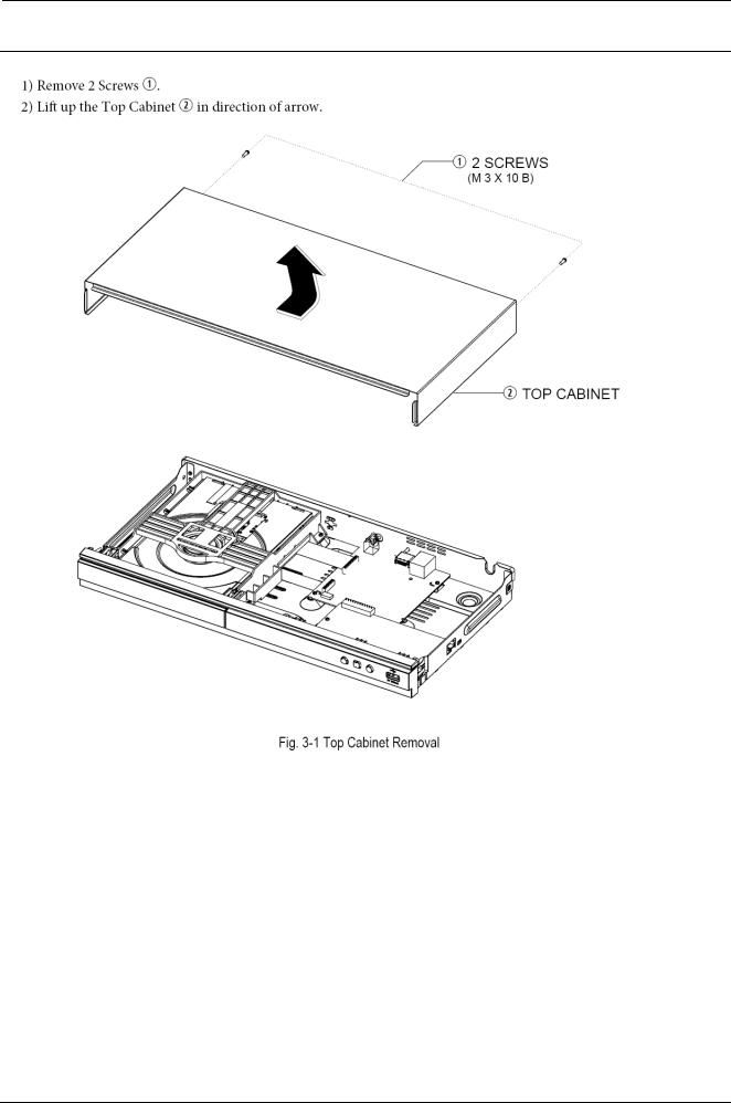
3.1.1. Top Cabinet Removal
3-2 |
Copyright© 1995-2011 SAMSUNG. All rights reserved. |
Loading...