


Rover LR3 2005 Owner Manual

OWNER’S HANDBOOK
Publication Part No. LRL 18 02 53 502 Version 2
© Land Rover 2005

Introduction
This handbook covers all current versions of the LR3 models and, together with the other books in
your literature pack, provides all the information that you need to derive maximum pleasure from
owning and driving your new vehicle.
For your convenience, the handbook is divided into sections, each dealing with a different aspect of
the vehicle. These are listed on the Contents page and you will find it worthwhile to take a little time
to read each one, and get to know your LR3 as soon as you possibly can. The more you understand
before you drive, the greater the satisfaction once you are seated behind the steering wheel.
The specification of each vehicle will vary according to territorial requirements and also from model
to model within the vehicle range. Some of the information published in this handbook, therefore,
may not apply to your particular vehicle.
To include changes made after the handbook is printed, it is sometimes necessary to issue one or
more handbook supplements. When reading this handbook, check the literature pack for possible
supplements.
Any further updates will be posted on the Land Rover internet site and can be accessed at
www.landrover.com in the OWNERS area.
* An asterisk appearing within the handbook text identifies features or items of equipment that
are either optional, or are only fitted to some vehicles in the model range.
Land Rover operates a policy of constant product improvement and therefore reserves the right to
change specifications without notice at any time. Whilst every effort is made to ensure complete
accuracy of the information in this handbook, no liabilities for inaccuracies or the consequences
thereof can be accepted by the manufacturer or the retailer, except in respect of personal injury
caused by the negligence of the manufacturer or the retailer.
All rights reserved. No part of this publication may be reproduced, stored in a retrieval system or
transmitted, in any form, electronic, mechanical, photocopying, recording or other means without
prior written permission from the Service Division of Land Rover.
As part of Land Rover’s environmental policy, this publication is printed on paper made
from chlorine-free pulp.
2

Handbook Contents
Quick Overview
Quick Overview . . . . . . . . . . . . . . . . . . . . . . 7
Reporting Safety Defects. . . . . . . . . . . . . . . . 7
Gas Station Information. . . . . . . . . . . . . . . 20
General Information
General Information . . . . . . . . . . . . . . . . . . 23
Controls & Instruments
Keys & Handsets . . . . . . . . . . . . . . . . . . . . 29
Locks & Alarms . . . . . . . . . . . . . . . . . . . . . 34
Seats . . . . . . . . . . . . . . . . . . . . . . . . . . . . . 41
Seat Belts. . . . . . . . . . . . . . . . . . . . . . . . . . 59
Child Restraints . . . . . . . . . . . . . . . . . . . . . 65
Airbag SRS. . . . . . . . . . . . . . . . . . . . . . . . . 70
Steering Column . . . . . . . . . . . . . . . . . . . . 78
Door Mirrors . . . . . . . . . . . . . . . . . . . . . . . 79
Facia Controls . . . . . . . . . . . . . . . . . . . . . . 81
Instruments . . . . . . . . . . . . . . . . . . . . . . . . 83
Settings Option* . . . . . . . . . . . . . . . . . . . . 85
Message Center* . . . . . . . . . . . . . . . . . . . . 87
Trip Computer* . . . . . . . . . . . . . . . . . . . . . 99
Warning Indicators. . . . . . . . . . . . . . . . . . 100
Audible Warnings. . . . . . . . . . . . . . . . . . . 106
Lamps & Indicators . . . . . . . . . . . . . . . . . 107
Wipers & Washers. . . . . . . . . . . . . . . . . . 111
Horn. . . . . . . . . . . . . . . . . . . . . . . . . . . . . 115
Electric Windows . . . . . . . . . . . . . . . . . . . 116
Sunroof . . . . . . . . . . . . . . . . . . . . . . . . . . 119
Heating & Ventilation . . . . . . . . . . . . . . . . 121
Interior Equipment. . . . . . . . . . . . . . . . . . 131
Loadspace Cover . . . . . . . . . . . . . . . . . . . 148
Audio System. . . . . . . . . . . . . . . . . . . . . . 151
In-Car Telephones . . . . . . . . . . . . . . . . . . 153
Voice Recognition . . . . . . . . . . . . . . . . . . 154
Land Rover Homelink® . . . . . . . . . . . . . . 156
Driving & Operating
Starting & Driving . . . . . . . . . . . . . . . . . . 161
Catalytic Converter. . . . . . . . . . . . . . . . . . 165
Fuel Filling . . . . . . . . . . . . . . . . . . . . . . . . 166
Park Distance Control . . . . . . . . . . . . . . . 170
Automatic Transmission . . . . . . . . . . . . . 172
Transfer Gearbox . . . . . . . . . . . . . . . . . . . 177
Cruise Control . . . . . . . . . . . . . . . . . . . . . 180
Brakes . . . . . . . . . . . . . . . . . . . . . . . . . . . 182
Dynamic Stability & Traction Control . . . . 188
Hill Descent Control . . . . . . . . . . . . . . . . . 190
Air Suspension. . . . . . . . . . . . . . . . . . . . . 193
Terrain Response. . . . . . . . . . . . . . . . . . . 199
Towing. . . . . . . . . . . . . . . . . . . . . . . . . . . 206
Towing Eyes. . . . . . . . . . . . . . . . . . . . . . . 214
Towing the Vehicle. . . . . . . . . . . . . . . . . . 217
Load Carrying. . . . . . . . . . . . . . . . . . . . . . 219
Front Lighting Systems . . . . . . . . . . . . . . 220
On-road Driving
On-road Driving . . . . . . . . . . . . . . . . . . . . 221
Off-road Driving
Off-road Driving . . . . . . . . . . . . . . . . . . . . 225
Off-road Driving Techniques . . . . . . . . . . 229
Maintenance
Maintenance. . . . . . . . . . . . . . . . . . . . . . . 235
Hood Opening . . . . . . . . . . . . . . . . . . . . . 238
Under-hood Covers . . . . . . . . . . . . . . . . . 239
Engine Compartment . . . . . . . . . . . . . . . . 240
Engine Oil. . . . . . . . . . . . . . . . . . . . . . . . . 242
Cooling System . . . . . . . . . . . . . . . . . . . . 243
Brakes . . . . . . . . . . . . . . . . . . . . . . . . . . . 245
Power Steering. . . . . . . . . . . . . . . . . . . . . 246
Washers. . . . . . . . . . . . . . . . . . . . . . . . . . 247
Wiper Blades . . . . . . . . . . . . . . . . . . . . . . 249
Battery . . . . . . . . . . . . . . . . . . . . . . . . . . . 251
Tires. . . . . . . . . . . . . . . . . . . . . . . . . . . . . 254
Cleaning & Vehicle Care. . . . . . . . . . . . . . 268
Identification Numbers. . . . . . . . . . . . . . . 271
Parts & Accessories. . . . . . . . . . . . . . . . . 272
Roadside Emergency
Wheel Changing. . . . . . . . . . . . . . . . . . . . 275
Emergency Starting . . . . . . . . . . . . . . . . . 286
Fuses . . . . . . . . . . . . . . . . . . . . . . . . . . . . 288
Bulb Replacement . . . . . . . . . . . . . . . . . . 297
Technical Data
Lubricants & Fluids . . . . . . . . . . . . . . . . . 311
3

Handbook Contents
Capacities. . . . . . . . . . . . . . . . . . . . . . . . . 313
Engines. . . . . . . . . . . . . . . . . . . . . . . . . . . 314
Electrical System . . . . . . . . . . . . . . . . . . . 315
Steering . . . . . . . . . . . . . . . . . . . . . . . . . . 316
Wheels & Tires. . . . . . . . . . . . . . . . . . . . . 317
Vehicle Weights . . . . . . . . . . . . . . . . . . . . 319
Dimensions. . . . . . . . . . . . . . . . . . . . . . . . 320
Towing . . . . . . . . . . . . . . . . . . . . . . . . . . . 321
4

Quick Overview
Quick Overview
REPORTING SAFETY DEFECTS . . . . . . . . . . .7
CALIFORNIA PROPOSITION 65
WARNING . . . . . . . . . . . . . . . . . . . . . . . . .7
THE REMOTE HANDSET . . . . . . . . . . . . . . . .8
EMERGENCY UNLOCKING . . . . . . . . . . . . . .8
FACIA CONTROLS . . . . . . . . . . . . . . . . . . . . .9
WARNING LIGHTS . . . . . . . . . . . . . . . . . . .10
SERVICE INTERVAL INDICATOR . . . . . . . . .11
LAMPS MASTER SWITCH . . . . . . . . . . . . . .11
WIPERS & WASHERS . . . . . . . . . . . . . . . . .12
CONFIGURABLE FEATURES . . . . . . . . . . . .14
AUTOMATIC TRANSMISSION
INTERLOCKS . . . . . . . . . . . . . . . . . . . . .15
PARKBRAKE . . . . . . . . . . . . . . . . . . . . . . . .15
AUTOMATIC TEMPERATURE
CONTROLS . . . . . . . . . . . . . . . . . . . . . . .16
AUTOMATIC MIRROR DIPPING . . . . . . . . .17
REMOVING THE ’BOOM’ . . . . . . . . . . . . . . .17
OCCUPANT DETECTION . . . . . . . . . . . . . . .17
VOICE RECOGNITION* . . . . . . . . . . . . . . . .18
ACCESS TO 3RD ROW SEATS . . . . . . . . . .19
Gas Station Information
FUEL FILLER . . . . . . . . . . . . . . . . . . . . . . . .20
OPENING THE HOOD . . . . . . . . . . . . . . . . .20
TIRE PRESSURES . . . . . . . . . . . . . . . . . . . .21
5

6

Quick Overview
Quick Overview
REPORTING SAFETY DEFECTS
If you believe that your vehicle has a defect
which could cause a crash, or could cause
injury or death, you should immediately inform
the National Highway Traffic Safety
Administration (NHTSA) in addition to notifying
Land Rover North America Inc.
If NHTSA receives similar complaints, it may
open an investigation and if it finds that a sa fety
defect exists in a group of vehicles, it may order
a recall and remedy campaign.
However, NHTSA cannot become involved in
individual problems between you, your Retailer
or Land Rover North America Inc.
Auto safety hotline
To contact NHTSA, you may either call the Auto
Safety HOTLINE toll-free at 1-800-424-9393 (or
202-366-0123 in the Washington, DC. area) or
write to: NHTSA, U.S. Department of
Transportation, DC 20590. You can also obtain
other information about motor vehicle safety
from the HOTLINE.
CALIFORNIA PROPOSITION 65
WARNING
WARNING
Engine exhaust, some of its constituents and
certain vehicle components contain or emit
chemicals known to the State of California to
cause cancer and birth defects or other
reproductive harm. In addition, certain fluids
contained in vehicles and certain products of
components wear contain or emit chemicals
known to the State of California to cause
cancer and birth defects or other reproductive
harm.
WARNING
Battery posts, terminals and related
accessories contain lead and lead
compounds. Wash hands after handling.
7
Quick Overview
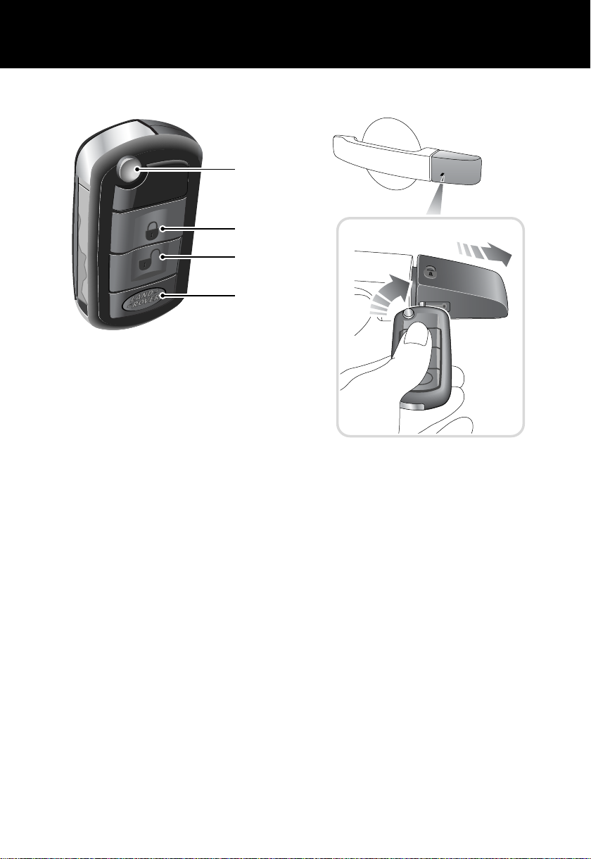
THE REMOTE HANDSET
1
2
3
4
H5350G
1. Key release button. Press to release the
folded key.
2. Lock button. A single press will lock all
doors. A second press within two seconds
will activate the perimetric alarm and th e tilt
* option. See, Perimetric alarm,
sensor
33, and Tilt Sensor*, 33.
3. Unlock button. Press once to disarm all
alarm features and unlock driver’s door
only. Press twice to open all doors. See,
Single-point entry, 34.
4. Land Rover button. The handset can be
programmed to initiate one of 3 features;
Panic alarm, Headlamp courtesy delay or
Air suspension control. See ’LAND ROVER’
BUTTON, 30.
Partial arming
If the driver’s door is not fully closed when the
handset lock button is pressed the vehicle horn
will activate. Until the door is fully closed the
vehicle will remain unlocked and unprotected
by the alarm system.
EMERGENCY UNLOCKING
H5801G
If the handset should fail there is an emergency
access feature on the left-hand front door lock.
With the key inserted into the slot beneath the
handle cap, the cap can be pulled outwards
slightly and then moved backwards to unhook
it. The key can now be used to unlock the
vehicle. See Emergency locking/unlocking, 36
8

FACIA CONTROLS
Quick Overview
10
1
9 8
2
7
H5353N
1. Headlamps and direction indicator controls
2. Wiper and washer control
3. Audio/display controls
4. Hazard warning light switch
5. Heater/air conditioning controls
6. Display screen
7. Electric parkbrake switch
8. Starter switch
9. Cruise control switches
10. Lamps master switch
Note: The precise specification and location of
the controls may vary according to territorial
requirements and from vehicle to vehicle.
*
*
43 5
FM1 14 : 54
KSAN FM2
6
For a full description of facia controls and their
functions, see FACIA CONTROLS, 81.
9

WARNING LIGHTS
1 2 3 4 6 7 8 9 105
Quick Overview
EXT C
23
11
H5356N
1. Battery charging (RED).
2. Low oil pressure (RED).
3. Safety belts (RED).
4. Airbag SRS (RED).
5. Door open (RED).
6. Brakes (RED).
7. Transmission (RED).
8. Transmission temperature (RED).
9. Tire pressure monitoring (RED).
10. Parkbrake (RED).
11. Message Center
*.
If one of these red warning lights illuminates, a
serious fault is indicated. Stop the vehicle and
refer to the main section of this handbook.
For a full description of warning lights and their
functions, see Warning Indicators, 100.
For a full description of the message centre and
its functions see Message Center*, 87.
10

Quick Overview
AUTO
SERVICE INTERVAL INDICATOR
H5804G
To view the next service date, turn the starter
key to position ’l’ and then, within 5 seconds,
press the System Check control button
(arrowed). The next service date is displayed
(dd.mm.yy) for 5 seconds.
For a full description of this feature, see
SERVICE INTERVAL INDICATOR, 97
LAMPS MASTER SWITCH
1
H5357L
2
1. Off.
2. Side lamps.
3. Low beam headlamps.
4. Auto lamps
*
For a full description of these functions, see
EXTERIOR LAMPS, 107.
3
4
AUTO
11

Quick Overview
WIPERS & WASHERS
AUTO
1
H5359G
The detent positions from fully pushed in are:
1. Off
2. Front fog lamps
3. Rear fog lamps
If front fog lamps are not fitted, the rear fog
lamps come on at the first pull of the switch.
Headlamp delay feature
When you leave the vehicle in a darkened
situation you can set the headlamps to remain
on for a while.
With the master switch in positions 2, 3 or 4,
turn the starter switch off and remove the key.
Turn the master switch to the off position. The
headlamps will remain on for up to 240
seconds. For a full description of this feature
and how to set the time delay, see Headlamp
courtesy delay, 108.
*
2
3
3
2
1
H5360G
1. Intermittent wipe
2. Normal speed wipe.
3. Fast speed wipe.
For a single wipe, pull the lever down and
release immediately.
Intermittent variable delay
H5361G
With the lever in position 1, rotate the switch to
vary the delay between wipes.
12

Windshield washer control
H5362G
Rear window wash/wipe
Quick Overview
H5363G
For more detailed information on the wash/wipe
system, see WINDSHIELD WIPERS, 111
13

Quick Overview
CONFIGURABLE FEATURES
Settings options (trip computer)
A number of features can be configured via the settings menu that can be displayed on the main
message centre. See SELECTING SETTINGS OPTION, 85.
SETTINGS CHOICE
TRIP DISTANCE UNITS (odometer) MILES/KM
FUEL USAGE UNITS MPG
l/100km
Km/l
o
EXTERNAL TEMPERATURE
OVERSPEED WARNING Off
HEADLAMP OFF DELAY 30/60/120/240 seconds
AUTO DOOR LOCK (speed related locking) ON/OFF
REVERSE MIRROR DIP ON/OFF
EASY ENTRY ON/OFF
RESTORE DEFAULT SETTINGS YES/NO
C or oF
20 - 250 km/h or 15 to 140 mph in 5-unit steps
(Units set as trip distance)
Remote handset
The following features can be configured by, or
for use with, the remote handset :-
• Single point entry, allowing only the drivers
door to be opened remotely. See,
Single-point entry, 34.
• Panic alarm, for personal protection. See,
’LAND ROVER’ BUTTON, 30.
• Headlamp courtesy delay, providing
lighting for personal safety. See,’LAND
ROVER’ BUTTON, 30.
• Air suspension control, allows remote
operation of the air suspension. See,’LAND
ROVER’ BUTTON, 30.
Starter key reminder
Provides an audible warning indicating that the
key is in the starter switch when the drivers
door is open. See,Starter key reminder, 106.
Daytime running lamps
Unless prevented by legislation, it is possible to
automatically switch on the exterior lamps
whenever the engine is running. See,Daytime
running lamps (Canada only), 109.
Speed dependant wiper mode
The wiper speed in all modes can be
automatically varied according to vehicle
speed. See,Speed-dependant mode, 112.
14
Quick Overview
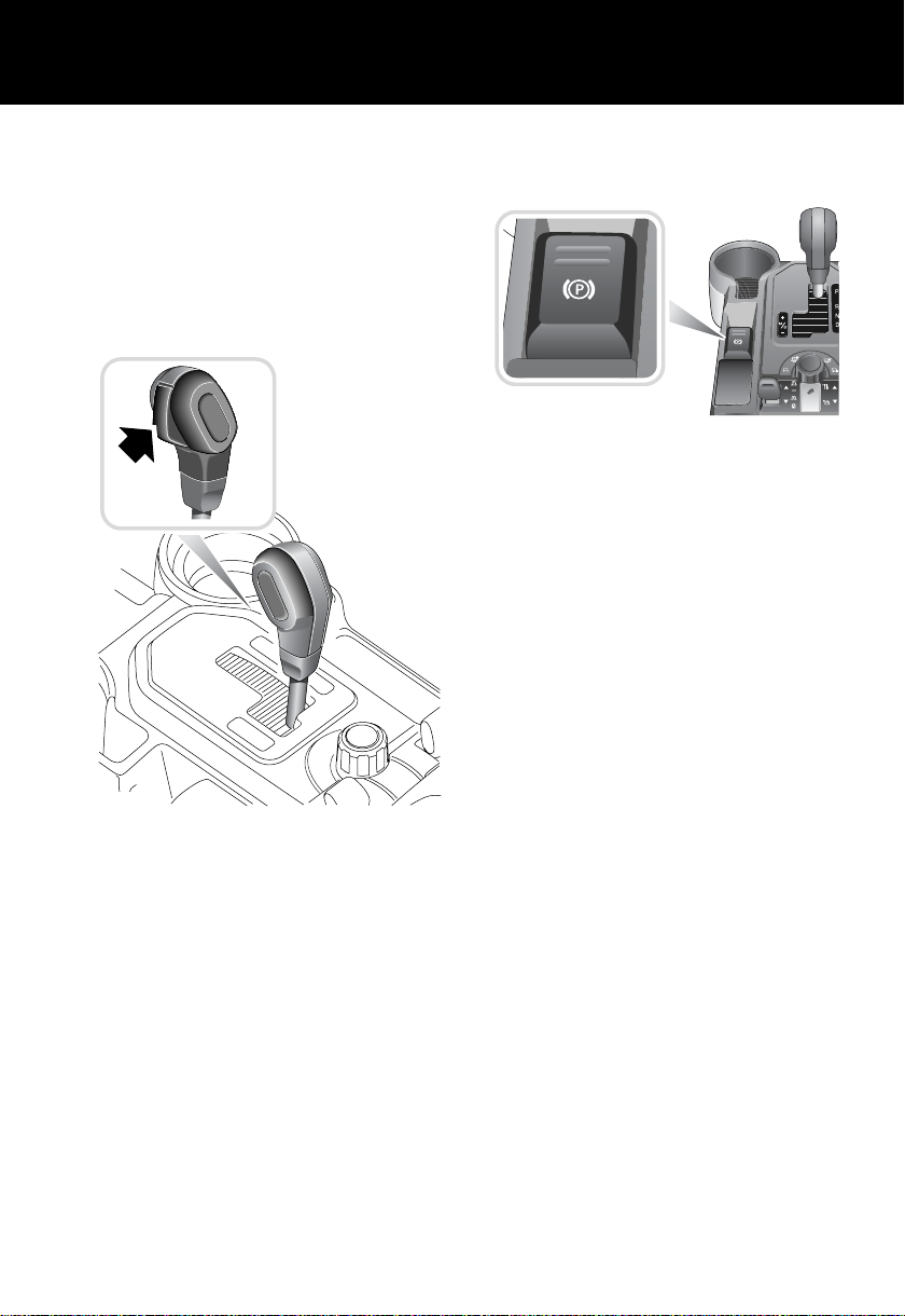
AUTOMATIC TRANSMISSION
INTERLOCKS
Automatic transmission can only be started
when the gear selector lever is in the ‘P’ (Park)
or ‘N’ (Neutral) position.
To move the lever from ‘P’ to ‘R’, ‘R’ to ‘P’ or ‘N’
to ‘R’, the selector release button (see inset)
must be pressed.
PARKBRAKE
The parkbrake is electrically operated.
H5806L
To apply the parkbrake, lift the lever and release
it. A RED indicator light in the instrument pack
will illuminate continuously.
To release the parkbrake the starter key must be
switched on and pressure must be applied to
the foot brake.
The parkbrake will release automatically if the
accelerator pedal is pressed. To delay this
release, hold the parkbrake lever in the raised
position until you are ready to move, then
release it.
For more detailed information on the parkbrake,
see PARKBRAKE, 185.
H5589L
To move from ‘P’ or ‘N’ into a drive gear
position, the foot brake must be applied.
For more detailed information on the automatic
gearbox, see USING AN AUTOMATIC
GEARBOX, 172.
15

Quick Overview
AUTOMATIC TEMPERATURE
CONTROLS
12
3 2 3
4
5
7
H5513N
1. Auto mode:
Press for fully automatic operation.
2. Blower control
3. Temperature controls:
Rotate anticlockwise for maximum cooling.
4. Air distribution controls
5. Air recirculation control - manual
6. Off
7. Economy mode
8. Rear environment
9. Heated rear windshield
10. Heated windshield.
11. Defrost mode
Press to defrost or demist the windshield.
12. Front seat heaters
For more detailed information on the climate
control system, see TEMPERATURE
CONTROLS, 121.
5
*
*
1
12
11
10
9
6
7
8
6
16

Quick Overview
AUTOMATIC MIRROR DIPPING
If your vehicle is fitted with the driver’s seat
memory option, the door mirrors may dip when
reverse gear is selected. This gives the driver a
view of the curbside to aid vehicle positioning
when reversing.
The feature is optional and can be adjusted by
the user.
For more detailed information on automatic
mirror dipping, see Automatic mirror
dipping*, 80.
REMOVING THE ’BOOM’
If a resonance/booming sound occurs with only
the rear windows open, lowering a front
window about 25 mm (1 inch) will eliminate the
condition. This will change the frequency of the
air volume moving in/out of the vehicle and
thus lessen or remove the booming sound.
OCCUPANT DETECTION
The front passenger seat is equipped with an
occupancy sensor which measures the weight
on the cushion and changes the passenger
airbag status.
The occupancy sensor operates as follows:
Seat
occupancy
status
Completely
empty
Low weight
occupant/
object
Heavy
occupant/
object
†
It is possible to receive an intermittent
indicator with an empty seat condition. This is
part of the system’s adaptive behaviour, and
does not affect the status of the passenger
airbag. However, if the indicator becomes
permanently illuminated when the seat is
definitely empty, then contact your Land Rover
Retailer immediately.
Passenger
airbag status
Deactivated No
Deactivated Yes
Activated No
Indicator
active
†
WARNING
Do not use a child restraint on a seat
protected by an operational air bag in front of
it.
There is a risk of death or serious injury when
the airbag deploys.
The safest place for children is properly
restrained in the rear seats.
For more details on occupancy detection, see
Occupant detection, 75
17
Quick Overview
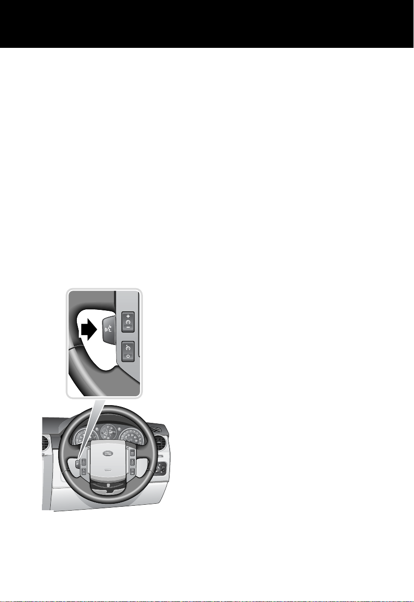
VOICE RECOGNITION*
Voice control provides a safe and convenient
way of operating the audio system without the
need to operate the controls manually. This
enables you to concentrate fully on driving the
vehicle, and removes the need to divert your
attention from the road ahead in order to
change settings, or receive feedback from the
system.
A number of voice commands are available, and
with a little experience you will find them easy
and convenient to use. Whenever you issue one
of the defined commands with the system
active, the voice control system converts your
command into a control signal for the audio
system. Your inputs take the form of dialogues
or commands. You are guided through these
dialogues by announcements or questions.
Activating the system
To activate voice control:
• Briefly pull the control paddle (your Audio
will mute at this point). A brief acoustic
signal will be heard, and ‘LISTENING’ will
be displayed on the main message centre
to indicate that the system is now waiting
for a voice command.
Note: It is only necessary to use the steering
wheel voice control paddle at the beginning of
each voice session.
Defined voice commands
The voice control system understands
predominate commands which need to be
quoted word for word.
An audio feedback of voice commands is
available. To activate the feedback, pull the
voice control paddle briefly and give one of the
following commands:
General commands
• Voice help To list all commands.
• Notepad Help To list Notepad commands.
Audio commands
• Radio help To list Radio commands.
• CD help To list CD commands.
Please refer to the Audio System Handbook
for full operating instructions.
H5786R
Navigation & Telephone commands
• Phone help To list telephone commands.
• Navigation help To list Navigation
commands.
Please refer to the Navigation, TV &
Telephone Handbook for full operating
instructions.
For further information see VOICE
RECOGNITION*, 154.
18

Quick Overview
ACCESS TO 3RD ROW SEATS
H5803G
Lower the headrest on the seat ahead of the 3rd
row seat.
Pull the release lever (upper inset) and fold the
seat into the table fold position. Now pull up the
access lever on the side of the folded seat and
tilt the seat forward into the access position.
Once access to the 3rd row seat is gained,
return the folded seat to the upright position.
For more detailed information on seat folding,
see SECOND-ROW SEATS - 5-SEAT VEHICLE,
50 , SECOND-ROW SEATS - 7-SEAT VEHICLE,
52 and THIRD-ROW SEATS, 57
19

Gas Station Information
Gas Station Information
FUEL FILLER
The fuel filler is located in the rear right-hand
wing. Press the fuel filler flap to open.
The fuel filler flap springs out, revealing the
filler cap.
Unscrew the filler cap and place it on the
projection on top of the hinge of the fuel filler
flap.
Insert the pump nozzle into the filler neck,
pushing aside the spring-loaded cover.
When delivery is complete, withdraw the nozzle
and replace the cap. Tighten the cap clockwise
until you hear it click three times.
Fuel type
V6 and V8 engines Premium unleaded gasoline with a CLC or AKI octane rating of 91
or higher. See TYPE OF FUEL, 168
Note: Mid or regular grade gasoline with a CLC or AKI octane rating
of not lower than 87 may also be used, but performance and fuel
economy will be reduced.
H5367G
OPENING THE HOOD
1. Inside hood release
2. Hood safety catch
2
1
H5368G
Engine oil top-up
V8 vehicles Use a 5W/30 oil to specification API GF3
V6 vehicles Use a 5W/30 oil to specification API GF4
Cooling system top-up
All vehicles to -36°C (-33°F) 50% mix of water and an approved antifreeze
Note: For more detailed information, see LUBRICANTS AND FLUIDS, 311
20

Gas Station Information
TIRE PRESSURES
Air pressure naturally increases in warm tires
(after the vehicle has been driven for a while). If
you have to check warm tires, you should
expect the pressures to have increased by
between 30 and 40 kPa (0.3 to 0.4 bar) (4 to 6
2
). In this circumstance, NEVER let air out
lbf/in
of the tires in order to match the recommended
pressures.
Loading condition kPa bar lbf/in
Normal operating conditions Front 230 2.3 33
Rear 250 2.5 36
Vehicle loaded to maximum gross vehicle weight Front 230 2.3 33
Rear 290 2.9 42
Compact spare tire (All operating conditions) 420 4.2 60
2
21

22

General InformationGeneral Information
General Information
23

General Information
HANDLING CHARACTERISTICS
WARNING
Your vehicle has a higher ground clearance
and hence, a higher center of gravity than
ordinary passenger cars, to enable the
vehicle to perform in a wide variety of off-road
applications. An advantage of the higher
ground clearance is a better view of the road
allowing you to anticipate problems.
The vehicle is not designed for cornering at
the same speed as conventional passenger
cars any more than a low-slung sports car is
designed to perform satisfactorily under
off-road conditions. If at all possible, avoid
sharp turns or abrupt manoeuvers. As with
other vehicles of this type, failure to operate
the vehicle correctly may result in loss of
control or vehicle rollover. For important
safety information, be sure to read the
‘On-Road’ and ‘Off-Road’ driving guidelines
given later in this handbook.
SYMBOLS
The following symbols used within the
handbook call your attention to specific types of
information.
This recycling symbol identifies those
items that must be disposed of safely in
order to prevent unnecessary damage to the
environment.
This symbol identifies those features that
can be adjusted or disabled/enabled by a
Land Rover Retailer.
WARNINGS IN THIS HANDBOOK
WARNING
Safety warnings are included in this
handbook. These indicate either a procedure
which must be followed precisely, or
information that should be considered with
great care in order to avoid the possibility of
personal injury.
Caution: Cautions are included in this
handbook. These indicate either a procedure
which must be followed precisely, or
information that should be considered with
great care in order to avoid the possibility of
damage to the vehicle.
WARNING LABELS ATTACHED
TO THE VEHICLE
Warning labels attached to your vehicle
bearing this symbol mean: DO NOT
touch or adjust components until you
have read the relevant instructions in
the handbook.
Warning labels showing this symbol
indicate that the ignition system utilises
very high voltages. DO NOT touch any
ignition components while the starter
switch is turned on!
24

General Information
PASSPORT TO SERVICE
The Passport to Service book included in your
literature pack contains important vehicle
identification information, details of your
entitlement under the terms of the Land Rover
Warranty, as well as useful consumer advice.
Most important of all, however, is the section
on maintenance. This outlines the servicing
requirements for your vehicle and also includes
the service record slips, which the Retailer
should sign and stamp to certify that the routine
services have been carried out at the
recommended intervals.
TIRE PRESSURE LABELS
MFD BY LANDROVER IN THE UK
DATE : MM/YY
GVWR: 3230KG (7121LB)
GAWR FRONT: 1450KG (3197LB)
235/70R17 TIRES, 7.0JX17 RIMS, AT 230KPA (33PSI) COLD
235/65R18 TIRES, 8.0JX18 RIMS, AT 230KPA (33PSI) COLD
255/60R18 TIRES, 8.0JX18 RIMS, AT 230KPA (33PSI) COLD
255/55R19 TIRES, 8.0JX19 RIMS, AT 230KPA (33PSI) COLD
T175/80R19 TIRES, 5.5JX19 RIM, AT 420KPA (60PSI) COLD
GAWR REAR: 1870KG (4123LB)
235/70R17 TIRES, 7.0JX17 RIMS, AT 290KPA (42PSI) COLD
235/65R18 TIRES, 8.0JX18 RIMS, AT 290KPA (42PSI) COLD
255/60R18 TIRES, 8.0JX18 RIMS, AT 290KPA (42PSI) COLD
255/55R19 TIRES, 8.0JX19 RIMS, AT 290KPA (42PSI) COLD
T175/80R19 TIRES, 5.5JX19 RIM, AT 420KPA (60PSI) COLD
THIS VEHICLE CONFORMS TO ALL APPLICABLE
U.S.FEDERAL MOTOR VEHICLE SAFETY
STANDARDS IN EFFECT ON THE DATE OF
MANUFACTURE SHOWN ABOVE
TESTMARK1234567890
Information on tire pressures for differing tires
and vehicle loadings is given on a label attached
to the ’B’ post on the driver’s side.
For further information on tire pressures, see
TIRE PRESSURES, 318, TIRE PRESSURE
MONITORING SYSTEM*, 266 , WHEELS &
TIRES, 317.
TOW BAR LABEL
TYPE : MULTI - PURPOSE PASSENGER VEHICLE
TIRE AND LOADING INFORMATION
SEATING CAPACITY
The combined weight of occupants and cargo should never exceed 668kg or 1473lbs
ORIGINAL TIRE SIZE COLD TIRE INFLATION PRESSURE
255/55R19
COMPACT SPARE TIRE
T175/80R90
H5768N
FRONT
REAR
COLD TIRE INFLATION PRESSURE
TOTAL 7
230kpa, 33PSI
290kpa, 42PSI
420kpa, 60PSI
FRONT 2 REAR 3 + 2
SEE OWNER'S
MANUAL FOR
ADDITIONAL
INFORMATION
H5371G
A label, located on the inside face of the rear
bumper access hatch, shows the attachment
and removal procedure for the tow bar system.
For information on removing and fitting the
detachable tow bar, see Towing, 206.
RTC500490
25

General Information
SUN VISOR LABELS
BRAKE PADS
Brake pads require a period of bedding in. For
the first 800 km (500 miles), you should avoid
situations where heavy braking is required.
Remember! Regular servicing is vital to ensure
that the brake pads are examined for wear and
changed periodically to ensure long term safety
and optimum performance.
IN AN EMERGENCY
Remember the breakdown safety code
• Wherever possible, consistent with road
safety and traffic conditions, the vehicle
should be moved off the main
thoroughfare, preferably into an
emergency lane. If a breakdown occurs on
a motorway, pull well over to the inside of
the hard shoulder.
• Switch on hazard lights.
• If possible, position a warning triangle or a
flashing amber light at an appropriate
distance from the vehicle to warn other
traffic of the breakdown, (note the legal
requirements of some countries).
front
• Consider evacuating passengers through
nearside doors onto the verge as a
precaution in case your vehicle is
accidentally struck by other traffic.
ta
H5789N
Always take careful note of warning information
about the airbag SRS affixed to the driver’s and
passenger’s sun visor.
An additional label, located on the ’B’ post,
warns against the use of rear-facing child seats
in the front passenger seat.
For further information concerning the airbag
SRS and the use of child restraints, consult the
relevant sections of this handbook.
26

General Information
ANTI-THEFT PRECAUTIONS
While it may be difficult to deter the
‘professional’ car thief, the majority of thefts are
carried out by unskilled opportunists.
Therefore, take vehicle security very seriously
and ALWAYS adopt this simple ‘four point’ drill
whenever you leave your vehicle - even for just
a few minutes:
1. Fully close all the windows (and the
sunroof).
2. Remove your valuable belongings (or hide
them out of sight).
3. Remove the starter key.
4. Superlock the vehicle using the remote
handset.
Thieves are attracted by ‘vulnerable’ vehic l es.
Even if you have followed the ‘four point’ drill,
there is still much you can do to make your
vehicle a less inviting target.
BE SAFE - NOT SORRY!
• Park where your vehicle can be easily seen
by householders and passers-by.
• At night, park in well lit areas and avoid
deserted or dimly-lit side streets.
• NEVER leave the keys in the vehicle.
• Do not keep important documents (or
spare keys) in the vehicle - the se ar e a rea l
bonus for the thief.
BREAKING-IN
Proper breaking-in will have a direct bearing on
the reliability and smooth running of your
vehicle throughout its life.
In particular, the engine, gearbox, brakes and
tires need time to ‘bed-in’ and adjust to the
demands of everyday motoring. During the first
500 miles (800 km), it is essential to drive with
consideration for the running-in process and
heed the following advice:
• LIMIT maximum road speed to 70 mph
(110 km/h) or 3,000 rev/min. Initially, drive
the vehicle on a light throttle and only
increase engine speeds gradually once the
breaking-in distance has been completed.
• DO NOT operate at full throttle or allow the
engine to labour in any gear.
• AVOID fast acceleration and heavy braking
except in emergencies.
27

General Information
ON-BOARD EVENT DATA
Service data recording
Service data recorders in your vehicle are
capable of collecting and storing diagnostic
information about your vehicle. This potentially
includes information about the performance or
status of various systems and modules in the
vehicle such as engine, throttle, steering or
brakes.
In order to properly diagnose and service your
vehicle, Land Rover and service and repair
facilities may access vehicle diagnostic
information through a direct connection to your
vehicle.
Event data recording
Other modules in your vehicle - event data
recorders - are capable of collecting and storing
data during a crash or near-crash event. The
recorded information may assist in the
investigation of such an event. The modules
may record information about both the vehicle
and the occupants, potentially including
information such as:
• How various systems in your vehicle were
operating.
• Whether or not the driver and passenger
seat belts were buckled.
• How far, if at all, the driver was depressing
the accelerator and/or the brake pedal.
• How fast the vehicle was travelling.
• Where the driver was positioning the
steering wheel.
To access this information special equipment
must be connected directly to the recording
modules. Land Rover do not access event data
recorder information without obtaining
consent, unless pursuant to court order or
where required by law enforcement, other
government authorities or third parties acting
with lawful authority.
Other parties may seek to access the
information independently of Land Rover.
28

Keys & Handsets
Controls & Instruments
KEYS AND HANDSETS
H5750G
You have been supplied with two remote
handsets with integral keys which operate all of
the vehicle’s locks.
The operation of all transmitter buttons on all
handsets will be inhibited whilst a key is in the
starter switch.
Note: The key transmitter may not operate
correctly in areas that are subject to
interference from other radio equipment
operating on a similar frequency. Areas where,
for example, equipment such as amateur radio ,
medical devices, telecommunications
equipment, or other remotely operated alarms
are in use may cause difficulty. If such
difficulties are experienced, tr y to opera te the
transmitter as close as possible to the vehicle,
or use the key in the door lock.
The keys supplied with your vehicle are
programmed to your security system - the
engine cannot be started without a key
programmed to your vehicle.
Caution: Keep the spare handset key in a safe
place - NOT IN THE VEHICLE!
The other two keys that you have received are
for locking the main glovebox.
Note: Should a key transmitter be lost or
damaged a replacement can only be obtained
from your Land Rover retailer, where it will be
programmed to your vehicle. The dealer will
require proof of ownership, and keep a log of all
enquiries for replacement key transmitters.
It is advisable to notify your retailer as soon as
possible if a key transmitter is lost or stolen,
and have the remaining transmitters
reprogrammed. This will prevent access to the
vehicle using the lost/stolen transmitter.
29

Keys & Handsets
Compliance
The handset complies with part 15 of the FCC
rules. Operation is subject to the following
conditions:
• This device may not cause harmful
interference.
• This device must accept any interference
received, including interference that may
cause undesired operation.
Any changes or modifications to the handset
not expressly approved by the manufacturer or
Land Rover North America could void the
user’s authority to operate the equipment.
Transmitter FCC ID: NT8-15K6014CFFTXA
Receiver FCC ID: LQN5752
Remote handset battery
The battery is rechargeable. The fact that the
battery needs recharging will be apparent from
the following:
• ’KEY BATTERY LOW’ will be displayed in
the main message center.
• A gradual deterioration in range and
performance will be noticed.
Insert the key into the starter switch and start
the engine. This will start to recharge the
handset battery.
Caution: The handset contains delicate
electronic circuits and must be protected from
impact and water damage, high temperatures
and humidity, direct sunlight and the effects
of solvents, waxes and abrasive cleaners.
Battery disposal
Used batteries should be recycled.
However, batteries are hazardous - you
should seek advice about disposal from
a Land Rover Retailer or your local authority.
’LAND ROVER’ BUTTON
Customer programmable button
The fourth button - marked with the Land Rover
logo - on the remote handset can be
programmed to give remote operation of one of
the following functions:
• panic alarm
• headlamp courtesy delay
• air suspension control
Note: Programming and subsequent use of the
’Land Rover’ button will not occur if the key is
in the starter switch.
WARNING
Be aware that the previously programmed
feature will be activated when the button is
initially pressed to start the programming
sequence.
30
 Loading...