


Rover 5377 - 12HP User Manual
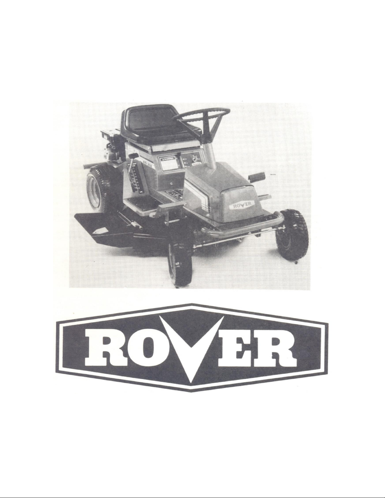
Ranger Auto - Drive
Owners Manual
Model No. 5377 – 12HP.
WARNING
• A mower is a high speed cutting tool. Safety precautions must be observed to reduce the risk of accident.
• Careless or improper use may cause serious injury.
• Be sure that you read and fully understand the contents of this Owner’s Manual. Should any point be unclear, contact
Rover-Scott Bonnar Limited, in your State or an authorised Rover-Scott Bonnar Service Agent for assistance.
• Keep the Owner’s Manual in a safe place for future reference. Read the Owner’s Manual periodically to ensure the
continued safe and proper use of the mower.

SAFETY INSTRUCTIONS
• A mower user must be in good physical condition and
mental health and not under the influence of any drug or
alcohol which might impair vision co-ordination or
judgement.
• Do not use a mower when tired or fatigued. Lack of
alertness may cause serious injury.
• Know your controls.
Read and understand Owner’s Manual before operating
mower. Learn how to stop the mower in an emergency. Refer
Operator’s Instructions.
• Do not lend or sell the mower without the Owner’s Manual.
• Be sure that anyone using the mower reads and fully
understands the information contained in this Manual and
knows how to safely operate the mower.
• Do not allow children or people unfamiliar with these
instructions to use the mower.
• Never mow whilst bystanders or pets are present in the
mowing area.
• Never carry passengers.
• Never mow while barefoot or wearing open sandals or
thongs. Wear long trousers and heavy non-slip shoes.
• It is advisable to wear suitable eye protection when
operating a mower.
• Before using, always visually inspect to see that the
blades, blade bolts, and cutter assembly are not worn or
damaged. Replace worn or damaged blades and bolts in
sets to preserve balance.
• Damaged blades and worn bolts are major hazards.
• Replace worn or faulty silencers.
• Always mount and dismount mower from left-hand side
(opposite side to discharge chute).
• Make sure the area to be mowed is cleared of sticks,
stones, bones, wire and debris. They could be thrown by the
blades.
• Store fuel in a cool place in a container specifically
designed for that purpose. In general, plastic containers are
unsuitable. Handle fuel carefully. It is highly flammable.
• Refuel outdoors only. Do not smoke when refueling
engine. Add fuel before starting engine. Never remove the
cap from the fuel tank or add petrol while the engine is
running. Allow engine to cool for several minutes before
refueling if engine is hot. If petrol is spilled, do not attempt to
start the engine, but move the mower away from the area of
the spill and avoid creating any source of ignition until the
petrol vapors have dissipated.
• Remove the fuel cap slowly to relieve fuel tank pressure.
• Check for fuel leaks while refueling or using the mower. If
a fuel leak is found, do not start or run the engine until the
leak is fixed and spilled fuel is wiped away.
• Take care not to get fuel on your clothing. If this occurs,
change your clothing immediately.
• Do not operate mower in confined space where exhaust
fumes (carbon monoxide) can collect.
• Mow only in good daylight.
• Start the engine carefully with feet well away from the
blades.
• When starting do not wrap the started rope around your
hand. Do not allow the started cord to snap back. Return the
starter grip slowly to allow the cord to rewind properly.
• Strictly follow the operator instructions before attempting
to start the machine.
• Never mow where machine could tip or slip.
• If machine stalls going uphill, stop blades and back slowly
down.
• Mow up and down slopes. Never mow across a slope.
Exercise extreme caution when changing direction on slopes.
Do not mow excessively steep slopes.
• Do not accelerate or stop the mower suddenly when on a
slope.
• Be extremely careful when using a mower on slopes. Stay
alert for holes in the terrain and other hidden hazards.
• Disengage cutter drive before mowing across gravel drives,
walks or roads.
• Do not mow in reverse. When reversing keep a careful and
continuous observation of the entire area behind the mower.
• Never use the mower unless all guards provided by Rover-
Scott Bonnar Limited are in position.
• Never disconnect the safety switches and never operate
the mower if any safety switch is inoperative.
• Never over-speed the engine or alter the governor settings.
Excessive speed is dangerous and shortens mower life.
• Take all precautions when leaving the mower unattended.
Disengage the cutter drive, set the park brake, shift into
neutral, stop the engine, and remove the key.
• Stop the engine and remove the key whenever you leave
the mower, even for a moment.
• Stop the engine and disconnect the spark plug lead and
inspect mower if:
a) The mower begins to vibrate abnormally: or
b) After striking a foreign object.
Repair the damage before continuing further operation of
the mower.
• Stop the engine and disconnect the spark plug lead before
clearing blockages, checking or working on the mower.
• Never pick up or carry a mower while it is operating.
• Where fitted, turn fuel tap off at the conclusion of mowing.
• When transporting in a vehicle, secure the mower to
prevent movement, roll-over, fuel spillage, and mower
damage.
• Keep all nuts, bolts and screws tight to be sure the
equipment is in safe working condition.
• Never modify the mower in any way. Use only replacement
parts made and guaranteed by Rover-Scott Bonnar Limited.
• Keep all safety devices (guards and switches) in place and
working.
• Keep the engine free of grass, leaves or excessive grease –
these can be a fire hazard.
• Store the mower in a well ventilated room away from
naked flames such as may be found in hot water heaters.

SAFETY FEATURES
Traction drive, blade drive and seat
safety interlock
Enclosed drives
Full footrests Convenient – easy to operate controls
Low centre of gravity, stable wide track
Parking brake
1

SPECIFICATIONS
ROVER RANGER
Machine Model No. 5377
Engine Model No. 281707
Single Cylinder Briggs & Stratton
4 Stroke 12Hp 465cc
Fuel Capacity 4.0 Litres
Oil Capacity 1.42 Litres
Lubrication Gear Impellor
Spark Plug type Champion CJ8
Spark Plug gap 0.7 to 0.8mm
Ignition type Magnetron
Engine Oil 10w-30 or SAE 30
TRANSMISSION
Auto-Drive system consists of a continuous belt being driven
by an idler pulley over two drive pulleys and around a return
pulley. Friction plates are brought into contact with the drive
pulleys to impart either forward or reverse motion to rear
drive wheels by means of a drive selector pedal on the right
side of the machine.
Ground speed at 3600 rpm is variable due to Auto – Drive
system depending on pressure applied to drive selector
pedal.
Max. speed = 8.6 km/hr
CUTTING HEAD
Model 160 Full floating pressed steel housing with right
side discharge. Width of cut 760 mm (30”).
TYRES
Front Tyres: 4.1 x 6 Tube
Pressure 140 KPA maximum
Rear Tyres: 16 x 6.5 x 8 Tubeless
Pressure 96 KPA maximum
CONTROLS
∗ Throttle control with Fast, Slow and Choke positions;
∗ Key switch with Off, On and Start positions;
To emphasise special information the words WARNING and
CAUTION are used.
WARNING: The safety of the user and others
involved.
Personal injury may result should this
information be disregarded.
CAUTION: Follow these instructions carefully to
avoid mower damage and loss of
warranty.
STEERING WHEEL
325MM Dia. Steering Wheel. 1 ¼ turns lock to lock.
CLUTCH/BRAKE PEDAL
Foot operated pedal. Left side of machine.
PARKING BRAKE KNOB
Hand operated catch. Left hand side. Used in conjunction
with clutch/brake pedal.
DRIVE SELECTOR
Foot operated pedal located on right side of machine. Spring
loaded so as to return to neutral position.
CUTTING HEIGHT
Lever right hand side. 8 height of cut positions from 15mm
to 65mm.
CUTTER DRIVE
Lever located left side of seat cowl.
GENERAL
Wheel Base: 135cm Length: 164cm
Track 63cm. R 69cm F Width: 80cm
Turning Circle: 5.8m Height: 95cm
Turning Radius: 2.0m Weight: 195kg
2

DESCRIPTION
Steering wheel
Roll Pin
Stone Guard Assy.
Spring Stone Guard
‘E’ Clip
Ignition Keys
Plug Spanner
LOOSE PARTS KIT
QTY
1
1
1
1
1
1
1
On steering shaft
Secure steering wheel to shaft
Fitted to cutter head
On stone guard pivot rod
In groove in pivot rod
To start machine
SETTING UP INSTRUCTIONS
USE
Fig. 2
INSTALL STEERING WHEEL
1. Slip steering wheel over steering shaft and align the wheel
hole with the shaft hole;
2. Insert drift punch – partially through the holes to maintain
alignment and insert roll pin in the opposite side; See
Fig.2.
3. Drive roll pin in until flush with the outside of wheel.
Fig. 3
FIT STONE GUARD
1. Slip spring into stone guard pivot rod so that the short leg
rests on top of the stone guard;
2. Now twist the spring as shown and feed the end of the
pivot rod into the forward pivot bracket: See Fig.3.
3. Insert the short end of the pivot rod fully into the rearward
pivot bracket;
4. Release the spring. It should spring down onto the top of
the cutter head and be tensioning the stone guard down;
Fig. 4
5. Secure by clipping an ‘E’ Clip into the groove on the pivot
rod. See Fig. 4.
INSTALLING THE BATTERY
BATTERY
1. Remove Battery as follows;
(a). remove terminal cable from battery;
(b). undo wingnuts and remove clamp bar.
2. The battery is not filled with Electrolyte. This should be
done by adding 33% strength battery acid to each cell
until plates are covered. Electrolyte must be purchased
from a local battery supply outlet.
IMPORTANT: DO NOT OVERFILL BATTERY. ACID WILL
OVERFLOW INTO OTHER PARTS OF THE MACHINE AND
SEVERE CORROSION AND DETERIORATION WILL RESULT.
3. Leave filler caps off and connect battery charger to
battery terminal. Charge at the rate indicated in the
instructions supplied with the battery.
4. After charging, check that Electrolyte is still covering
plates, if not, add to correct level. Install filler caps.
5. Replace battery and secure.
6. Install the positive (red) cable to the positive (+)
terminal and the negative (black) cable to the negative
(-) terminal.
Secure for good electrical contact.
3

BEFORE OPERATING
FILL CRANKCASE WITH OIL
The rider mower may be delivered without oil in the
crankcase. Oil must be added before attempting to
start the engine.
1. Place machine on level surface. Ensure that the
oil plug is securely tightened. Clean around
dipstick.
2. Unscrew and remove dipstick from oil filler tube.
3. Insert funnel into filler tube and slowly add oil in
accordance with the engine manufacturer’s
direction.
NOTE: Avoid premature engine failure by ensuring
the funnel is clean so contaminants are not
introduced into the crankcase. Wipe any oil
spills so it will not cause dirt to collect on the
engine.
4. Ensure oil level is at the full mark on the dipstick,
when screwed completely in. When finished
replace dipstick and retighten.
NOTE: See Maintenance Instructions.
FILL FUEL TANK – See Safety Instructions.
Use only regular grade or unleaded petrol.
Do not mix oil with petrol – engine damage may result.
1. Clean around fuel tank cap so foreign matter cannot
enter tank when cap is removed.
2. Using a funnel, fill tank with regular grade or unleaded
petrol. Replace cap.
3. Wipe up any petrol that may have spilled.
CHECK TYRE PRESSURE
Check and maintain tyre pressure at 140KPA (20 PSI) front
and 96KPA (14 PSI) rear maximum.
ADJUSTING THE SEAT
Tip the seat forward,
loosen the seat securing
screws. Relocate the seat
for operator comfort.
Tighten the seat securing
screws and lowers the seat
See Fig.5
Fig. 5
CONTROLS
Fig. 6
1. Throttle Control – Mounted on the control panel and connected
to the engine carburetor controls. Has the symbols for Slow,
Fast and Choke.
2. Ignition Switch – This switch is part of the battery ignition
system and has three positions marked for Off, On and Start.
The switch is key operated and automatically returns to the On
position from Start position when released.
3. Brake/Clutch – Foot operated pedal on left side of machine.
Depressing the pedal disengages the drive belt and engages
Brake Disc.
4. Parking Brake – H and operated knob left hand side.
Depressing the brake clutch foot pedal enables this knob to be
engaged and disengaged. Brake is locked on with knob in up
position.
5. Drive Selection – Foot operated right hand side. Depress with
toe pressure gives forward motion; depress with heel gives
reverse motion. Automatically returns to neutral position.
6. Cutting Height Adjuster – Located on right of seat with low cut
at bottom and high cut at the top setting.
7. Cutter Drive – Lever located on left hand side of seat mounting
box. Down position disengages blade drive and applies blade
brake, Up position engages blades.
4

OPERATING INSTRUCTIONS
AUTO – DRIVE OPERATION
Forward and backward movement of the mower is controlled by the drive selector pedal. As with a motor vehicle,
speed is controlled by the amount of pressure on the drive selector pedal. Ensure that the mower user is familiar with
this means of operation before operating the mower, particularly in tight or confined areas.
TO START ENGINE
NOTE: The engine will not start unless the cutter drive is
disengaged, and clutch/brake pedal is depressed.
1. Depress clutch/brake pedal – Apply the parking brake
2. Move the drive selector to neutral
3. Disengage the cutter drive
4. Move the throttle lever to the choke position
5. Turn the ignition key to the start position and release
when the engine starts
6. Move the throttle lever to about ¼ position
TO MOW OR DRIVE
1. Depress clutch/brake pedal
2. Disengage the parking brake
3. Select height of cut
4. Move throttle to about ¾ position
5. Engage cutter drive
6. Select desired drive
7. Slowly release clutch/brake pedal to move off
TO STOP ENGINE
1. Depress clutch/brake pedal
2. Shift the drive selector to neutral
3. Disengage the cutter drive
4. Apply the parking brake
5. Move throttle lever to the slow position
6. Turn the ignition key to OFF. Remove the keys
TO STOP IN AN EMERGENCY
1. Depress brake/clutch pedal and drive selector pedal
together. (This disengages power from the engine and
engages the disc brake)
2. Apply park brake and lock
3. Move throttle to slow position and switch off ignition key
4. Dismount from mower if it is safe to do so
IMPORTANT
1. The parking brake should always be applied before
leaving the machine
2. The parking brake must be released before attempting to
drive
3. Depress the clutch/brake pedal-when starting or coming
to rest
4. Do not use sudden directional reversal which can cause
wheel spinning
ENGAGING CLUTCHES
When engaging the cutter drive lever or releasing the
clutch/brake pedal, always operate slowly. Do not use a
jerking motion. Moving these controls too fast could
possibly overload and stall the engine.
WARNING: To avoid loss of control always come to a
complete stop before changing drive direction
and slow down before turning.
REMEMBER
1. Always look behind the machine before reversing
2. Do not refuel when the engine is running or while the
engine is hot
3. Keep bystanders away – Keep hands and feet clear of
moving parts
4. Keep machine clean of grass and debris
5. Keep all safety devices (guards and switches) in place
and working
Periodically check the machine and the cutting mechanism.
If parts are worn or need replacing do so by using only
Genuine Rover Replacement Parts.
There is a comprehensive Ranger Spare Parts List contained
in this book to help you select the right part quickly.
Before working on the mower, disconnect the spark plug lead
from the spark plug and place it where it cannot contact the
spark plug.
Check your Rover Ranger frequently for loose nuts, bolts,
belts etc, and keep these items correctly tightened and
adjusted.
Note: A check after the first two hours of operation is
recommended. Engine failure or rapid engine wear
mainly result from the following causes –
1. Dirt or abrasives entering the engine via the air
cleaner due to –
a. The air cleaner element not being serviced
regularly, or
b. The air cleaner damaged or dislodged
2. Dirt or abrasives entering the engine via the oil
filler tube due to –
a. Using a funnel not cleaned of dirt and grit,
b. Topping up with contaminated oil. Oil stored
in an unclean container
3. Lack of oil. It is important to –
a. Check the oil level regularly (every 5 hours of
operation)
b. Maintain a full sump
5

MAINTENANCE INTERVAL CHART
See
Page
Change Oil (Initial) 6 X
Change Oil (Periodic) 6 X
Check Interlock 11 X X
Check Cutting Blades - X X
Check Cutting Unit Brake 9 X
Check Rear Wheels Brake 9 X
Lubricate Pivot Points 7 X
Lubricate Drive Chain 7 X
Lubricate Throttle Cable 7 X
Grease Front Axle Spindles 7 X
Service Air Cleaner 6 X
Check Spark Plug 6 X
Check Drive Belts 10 X
Check Drive Chain 10 X
Check Tyre Pressure 4 X
Clean Outside of Engine - X
Clean Cutter Housing - X
Paint Chipped Surfaces - X
AIR CLEANER: Dual Element Type –
1. Remove two cover knobs and remove air cleaner
cover.
2. Remove foam pre-cleaner, if so equipped
a. Wash pre-cleaner in liquid detergent and warm
water to remove dirt
b. Wrap pre-cleaner in cloth and squeeze dry
c. Saturate foam in engine oil. Squeeze to remove
excess oil.
3. Remove two nuts from top of cartridge.
4. Remove cartridge and clean air cleaner body carefully
to prevent dirt from entering carburetor. Brush dirt
from lower air cleaner body into duct.
5. Clean cartridge by gently tapping on flat surface
a. If very dirty, replace cartridge or wash in a low or
nonsudsing detergent and warm water solution
b. Rinse thoroughly from INSIDE OUT until water is
clear
c. Cartridge must be allowed to stand and air dry
thoroughly before using.
6. Reassemble air cleaner.
NOTE: Nuts holding air cleaner cartridge must be installed
with fiber washers down on cartridge plate to
prevent dirt from entering carburetor. Tighten nuts
by hand. Over tightening could collapse cartridge.
NOTE: Petroleum solvents, such as kerosene, are not to
be used to clean cartridge. They may cause
deterioration of the cartridge. DO NOT OIL
CARTIRIDGE. DO NOT USE PRESSURISED AIR TO
OIL CHANGE
See engine manufacturer’s instructions.
1. Place machine on a level surface. Start and run engine
for a period to warm the oil.
CLEAN OR DRY CARTRIDGE.
5
Hours
2. Fit drain tube to drain fitting; see Fig.8.
3. Place an oil pan under the end of drain tube;
4. Open the drain fitting about 1 turn and allow the oil to
5. Retighten drain fitting and refill sump with new oil. For
SPARK PLUG
The spark plug gap gradually increases during engine running
and should be checked periodically and whenever the engine
malfunctions.
1. Clean around spark plug area so that dirt will not enter
2. Disconnect spark plug lead and remove spark plug
3. Check condition of electrodes and ensure there is no
4. Carefully clean the spark plug. Do not grit blast
5. Set the gap to .8mm (.30”)
6. Install plug in engine and tighten to 20Nm. If a torque
7. Refit high tension lead. Push onto plug firmly.
25
Hours
drain completely;
correct viscosity and service classification, see the engine
manufacturer’s instructions.
engine when plug is removed
damage to insulator
wrench is not available hand tighten plug. Then with tube
spanner tighten plug about 1/12 of 1 turn
PERIODIC SERVICE EVERY 25 HRS
50 75 100 125 150 175 200
6

MAINTENANCE
COOLING SYSTEM
The Ranger has an air cooled 4 stroke engine. It must be
cleaned frequently. Remove any build-up of grass, dirt or other
debris from the -
1. Cylinder;
2. Cylinder head cooling fins;
3. Cooling air intake screen and;
4. Carburetor governor levers and linkages.
This will ensure adequate cooling and correct engine speed.
THROTTLE CONTROL
Proper choke and stop switch operation is dependant on
adjustment of remote controls –
1. Loosen outer cable clamp screw (D) on engine; See
Fig.9.
2. Set throttle control to choke position;
3. Adjust outer cable under clamp plate so that choke is
operated;
4. Tighten clamp plate screw and check –
a. Choke does not operate in fast position,
and
b. Stop switch operates correctly.
5. Move throttle to the slow position and adjust the slow
running stop screw (B) to give an engine speed of 1700
to 1800 RPM.
6. Adjust the idle needle valve (C) slowly in (lean) and out
(rich) until engine idles smoothly.
7. Reset engine idle speed.
8. Check operation. Engine should increase speed
without hesitation when throttle control is moved
quickly from slow to fast. If the engine tends to die out,
adjust the high speed needle valve 1/8 turn anticlockwise until engine accelerates smoothly.
Never tamper with the engine governor setting.
Changing the engine governor speed will void engine
warranty.
CARBURETOR ADJUSTMENT
The carburetor has been factory set and should only require
occasional fine tuning. See Figs.9 & 10.
1. Close high speed needle valve (A) in bottom of
carburetor bowl. Close finger tight in clockwise
direction;
2. Open (anti-clockwise) the needle valve 2 turns (that is
an approx. setting);
3. Start engine and let it warm up. Approx. 2 minutes.
Cutter drive must be disengaged. Speed Select-or must
be in Neutral position and Park Brake applied, air
cleaner must be fitted and secured and fuel tank must
be half full.
4. With the engine running at high speed, adjust the
needle valve 1/8 turn at a time. Clockwise or anticlockwise until engine runs smoothly.
NOTE: Allow several seconds between each adjustment for
engine to adapt to the new setting
LUBRICATION GENERAL
Using General Purpose Grease – (Every 25 hours)
- Grease nipples on front wheel pivots. See Fig.11
- Front Axle beam guides
- Grease nipples on steering pivot blocks Fig.21
- Steering gears Fig.21
- Grease nipple on engagement lever pivot Fig.23
Using Clean Engine Oil –
- Jockey pivot arms
- Throttle control cable Fig.9
- Chain Fig.23
7
 Loading...