


Rover DEFENDER 1997 Owner Manual

CONTENTS
SECTION 1 Introduction .......................................................... 1
SECTION 2 Controls & instruments ........................................ 7
SECTION 3 Driving & operating ............................................. 33
SECTION 4 Owner maintenance ............................................. 69
SECTION 5 Workshop maintenance........................................ 103
SECTION 6 General data ......................................................... 121
SECTION 7 Parts & accessories............................................... 129
SECTION 8 Off-road driving.................................................... 133
Index ..................................................................... 147
In-car entertainment
Publication No. LRL0095NAS
1996 RoverGroup Limited
Published by Technical Communications

Introduction
PASSPORT TO SERVICE
The Passport to Service included in your
literature pack, contains important vehicle
identification information, details of your
entitlement under the terms of the Land Rover
warranty, as well as useful consumer advice.
Most important of all, however, is the section
on maintenance. This outlines the servicing
requirements for your vehicle, as well as
incorporating the service record slips, which
the dealer should sign and stamp to certify
that routine services have been carried out at
the recommended intervals.
WARNING
Safety warnings are included in this
handbook. These indicate either a procedure
which must be followed precisely, or
information that should be considered with
great care in order to avoid the possibility of
personal injury or serious damage to the
vehicle.
WARNING LABELS ATTACHED TO THE
VEHICLE
Warning labels attached to your
vehicle bearing this symbol
mean: DO NOT touch or adjust
components until you have read the relevant
instructions in the handbook.
Warning labels showing this
symbol indicate that the ignition
system utilises very high
voltages. DO NOT touch any ignition
components while the starter switch is
turned on!
WARNING
Your vehicle has a higher ground clearance
and, therefore, a higher centre of gravity
than ordinary passenger cars. This will
result in different handling characteristics.
Inexperienced drivers should take additional
care, particularly in off-road driving
situations and when performing abrupt
manoeuvres on unstable surfaces.
3

Introduction
VEHICLE IDENTIFICATION NUMBER (VIN)
If you need to communicate with a Land
Rover dealer, you may be asked to quote the
Vehicle Identification Number (VIN).
The VIN and other information concerning the
vehicle, can be found on a plate, located in the
driver’s footwell (this should also match the
VIN recorded in the Passport to Service).
In addition, the Federal VIN plate is mounted
to the vehicle body, in such a position that it is
visible from the outside, through the bottom
corner of the windscreen on the driver’s side.
ANTI-THEFT PRECAUTIONS
While it may be difficult to deter the
’professional’car thief, the majority of thefts
are carried out by unskilled opportunists.
Therefore, take vehicle security very seriously
and ALWAYS adopt this simple ’five point’
drill whenever you leave your vehicle - even
for just a few minutes:
• Fully close all the windows and the
sunroof (if fitted).
• Remove your valuablebelongings (or hide
them out of sight).
• Remove the starter key.
• Engage the steering lock (by slightly
turning the wheel until it locks).
• Lock all the doors.
Thieves are attracted to ’vulnerable’ vehicles.
Even if you have followed the ’five point’ drill,
there is still much you can do to make your
vehicle a less inviting target.
BE SAFE NOT SORRY!
• Park where your vehicle can easily be seen
by householders and passers-by.
• At night, park in well lit areas and avoid
deserted or dimly lit side streets.
• At home, if you have a garage, use it - and
NEVER leave the keys in the vehicle.
• Do not keep important vehicle documents
(or spare keys) in the vehicle - these are a
real bonus for the thief.
4

Introduction
IMPORTANT INFORMATION
Remember the breakdown
safety code
If a breakdown occurs while travelling:-
• Wherever possible, consistent with
road safety and traffic conditions,
the vehicle should be moved off the
main thoroughfare. If a breakdown
occurs on a freeway, pull well over
to the inside of the hard shoulder.
• Switch on hazard lights.
• If possible, position a warning
triangle or a flashing amber light at
an appropriate distance from the
vehicle to warn other traffic of the
breakdown (note the legal
requirements of some areas in this
respect).
• Consider evacuating passengers
through the right hand doors away
from the road as a precaution in
case your Defender is struck by
another vehicle.
5

SECTION 2
Controls & instruments
In this section of the handbook you will find
descriptions of the controls and instruments
on your vehicle.
For your own safety, it is most important to
read this section fully and to gain a thorough
understanding of all the controls before
driving.
Section Contents Page
Controls 9.......................................................
Door locks 10.................................................
Seats 11.........................................................
Seat belts 13...................................................
Instruments 17...............................................
Warning lights 18...........................................
Lights & indicators 20....................................
Wipers & washers 21.....................................
Switches 23....................................................
Windows 24...................................................
Sunroof 25.....................................................
Heating & ventilation 26.................................
Air conditioning 29.........................................
Interior equipment 30.....................................
7

Controls
1. Heating & ventilation controls
2. Warning lights
3. Tachometer
4. Temperature gauge
5. Fuel gauge
6. Speedometer
7. Heater fan control
8. Ventilator control
9. Rear screen heater switch
10.Rearscreen wiper switch
11.Ashtray
12.Rearscreen washer switch
13.Clock
14.Cigarlighter
15.Ventilatorcontrol
16.Hazardwarning light switch
17.Hoodrelease handle
18.Fusebox cover
19.Transfergear lever
20.Maingearchange lever
21.Parkingbrake lever
22.Acceleratorpedal
23.Windscreenwash/wipe control
24.Brakepedal
25.Starterswitch and steering lock
26.Lightingswitch
27.Instrumentillumination switch
28.Lighting,direction indicator & horn switch
9

Door locks
From outside the vehicle, turn the key towards
the rear of the vehicle to lock and towards the
front to unlock.
From inside the vehicle, each door can be
individuallylocked, by depressing the
appropriate sill locking button.
Front doors
Door sill locking buttons
KEYS
You have been supplied with two sets of keys,
comprising:
• a black key for operating the starter
switch.
• a plain metal key for operating the door
locks.
• a grey key for operating the cubby box
lock.
Key numbers
The starter key and glovebox key numbers are
stamped on a tag attached to their respective
key rings. The door lock key number is
stamped on the key itself. All key numbers
should be entered on the Security Information
card.
WARNING
Keep the spare keys and key tags in a safe
place - NOT IN THE VEHICLE!
Ensure the key numbers are recorded on the
Security Card supplied with your literature
pack - DO NOT KEEP THE CARD IN THE
VEHICLE!
WARNING
DO NOT depress the sill buttons as a means
of locking the doors from outside the vehicle
(this practice - known as ’slam locking’ - is
not recommended, because keys can be
locked inside accidentally).
Taildoor
From outside, use the key to lock and unlock.
From inside and with the door closed, push
the locking button up to lock and down to
unlock (as illustration).
10

Seats
FRONT SEAT ADJUSTMENT
WARNING
To avoid the risk of loss of control and
personal injury, never adjust the driver’s
seat or seatback while the vehicle is in
motion.
DO NOT allow occupants to travel with the
seat backs reclined steeply rearwards.
Optimum benefit is achieved from the seat
belt, with the seat back angle set to 15
degrees from the vertical (upright) position.
Forward/backward movement
Lift the bar at the front of the seat base to
slide the seat forward or back. Ensure the seat
is locked in position before driving.
Backrest movement
Lift the lever and lean backwards or forwards
to achieve the desired angle, then lower the
lever to lock.
11
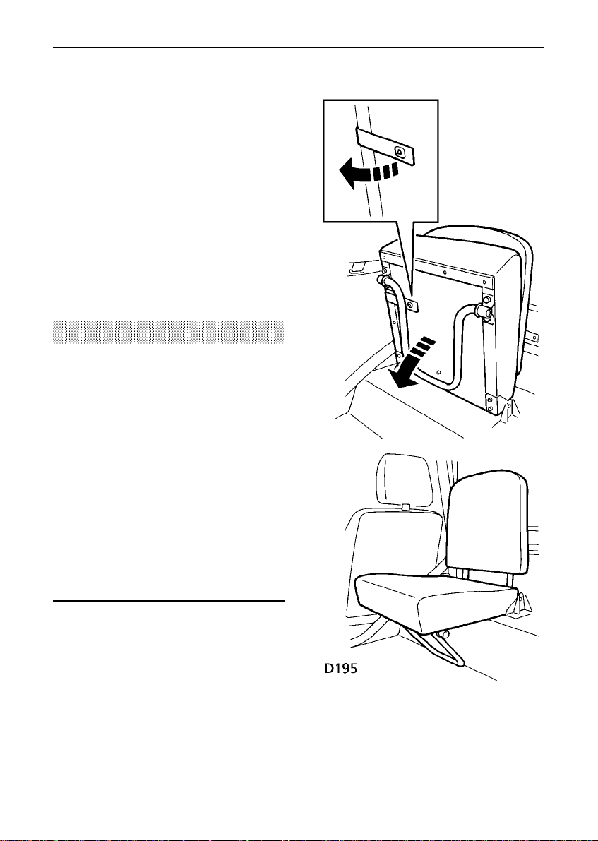
Rear seats - (Station wagons)
Station wagon models are fitted with inward
facing rear seats, which can be folded away
when not in use.
To erect the seats, release the strap securing
the seatbase, pull out the seat stand and fold
down the seatbase, ensuring that the seat
stand locates where the vehicle floor meets
the wheel arch (see illustration).
NOTE: Soft top vehicles can be fitted with
forward facing rear seats, provided that a full
Safari roll cage has been installed.
WARNING
DO NOT adjust the seats or seat stands
while the vehicle is in motion.
When the seat is erected, the seat stand
should be visually checked and physically
tested, to ensure that the seatbase is secure
before driving.
DO NOT allow the rear seats to be used
unless the seat stand is in the correct
position.
Ensure that rear seat passengers wear seat
belts at all times.
DO NOT carry passengers in the rear of the
vehicle unless rear seats are fitted.
Seats
12

Seat belts
SEAT BELT SAFETY
Seat belts are life saving equipment.
In a collision, unrestrained passengers can be
thrown around inside the vehicle, or possibly
thrown out of the vehicle, resulting in injury to
themselves and to other occupants. DO NOT
take chances with safety!
• DO make sure ALL passengers are
securely strapped in at all times - even for
the shortest journeys.
• ALWAYS adjust seat belts to eliminate any
slack in the webbing, and to ensure that
the diagonal belt passes across the
shoulder without slipping off or pressing
on the neck.
• ALWAYS fit the lap strap as low on the
hips as possible (never across the
abdomen).
• DO NOT slacken the webbing by pulling
the belt away from the body - to be fully
effective, the seat belt must be in full
contact with the body at all times.
• DO have seat belts checked if the vehicle
has been involved in an accident.
• DO NOT allow front seat occupants to
travel with the seat backs reclined steeply
rearwards. Optimum benefit is obtained
from the seat belt, with the seat back angle
set to 15 degrees from the upright
(vertical)position.
• DO use the seat belts to secure large items
of luggage that are to be carried on the
seats - in the event of an accident,
insecure items become flying missiles
capable of causing serious injury.
• DO NOT fit more than one person into a
belt, or fit a seat belt that is twisted or
obstructed in any way that could impede
its smooth operation.
• DO NOT allow foreign matter (particularly
sugary food and drink particles) to enter
the seat belt locks - such substances can
render the locks inoperative.
WARNING
Pregnant women should ask a doctor for
advice about the safest way to wear seat
belts.
Ensure that all seat belts are worn correctly
- an improperly worn seat belt increases the
risk of death or serious injury in the event of
an accident.
13

Seat belts
WARNING
At all times, occupants should wear a seat
belt for their protection in the event of a
collision or sudden stop. In some
circumstances, perhaps due to the vehicle
being on a slope, the automatic locking
mechanism may engage, preventing the
initial extension of the belt. This is not a
fault - ease the belt free and use it.
Lap belts
To adjust, pull the slider along the belt and
feed the webbing through the buckle until the
belt is comfortably tight. When not in use, the
lap belts should be stowed behind the seat
back.
Fastening the inertia reel belts
Draw the belt over the shoulder and across
the chest, and insert the metal tongue plate
into the lock nearest the wearer - a ’click’
indicates that the belt is securelylocked.
Seat belts are designed to bear upon the bony
structure of the body (pelvis, chest and
shoulders) and can only be worn safely with
the webbing crossing the shoulder MIDWAY
BETWEEN THE NECK AND THE EDGE OF THE
SHOULDER and with the seats in a normal
UPRIGHT position - DO NOT allow the front
passenger to travel with the seat steeply
reclined.
14

Seat belts
Infant and child restraints
All infant and child restraint systems are
designed to be secured in forward facing
vehicle seats by means of a lap belt or the lap
portion of a lap/shoulder belt.
When installing and using any infant or child
restraint system, always follow the
instructions provided by the manufacturer
concerning installation and use. Failure to
properly secure the child restraint system in
the vehicle can endanger the child in a
collision or sudden stop and cause injury to
other passengers.
The front passenger seat belt is fitted with a
retracting lock mechanism, providing extra
security for a child restraint in the event of an
accident. To activate the passenger seat belt
lock mechanism, pull the seat belt out to its
full extent and then allow it to retract until it is
the correct length to secure the child seat. The
seat belt will now be locked in that position
until released by undoing the seat belt in the
normal way.
Never leave a child unattended in your
vehicle.
WARNING
Infants and children too small for seat belts
should be restrained in a child safety seat or
restraint system, appropriate to their age
and/or size, and which is approved for use
in your vehicle. Always ensure that the
manufacturer’s fitting instructions are
followed exactly.
• Do not fit child safety seats or restraint
systems to the inward facing rear seats.
15

Seat belts
Caring for seat belts
Regularly inspect the belt webbing for signs of
wear, paying particular attention to the fixing
points and adjusters. Always replace a seat
belt that has withstood the strain of an impact
or shows signs of fraying.
DO NOT bleach or dye the webbing. Clean the
webbing using warm water and non-detergent
soap only - allow to dry naturally and DO NOT
retract the belt until completely dry.
Testing inertia reel belts
From time to time carry out the following
tests:
1. With the seat belt fastened, give the
webbing near the buckle a quick upward
pull. The buckle must remain securely
locked.
2. With the seat belt unfastened, unreel the
webbing to the limit of its travel. Check
that unreeling is free from snatches and
snags.
3. With the webbing half unreeled, hold the
tongue plate and give it a quick forward
pull. The safety mechanism must lock
automaticallyand prevent any further
unreeling.
16

Instruments
1. Speedometer
Indicates road speed in miles and/or
kilometres per hour.
2. Odometer and trip odometer
Indicates the total distance or the individual
journey distance travelled by the vehicle press and releasethe reset button (3) to
change between the two.
3. Odometer and trip odometer mode/reset
button
Press and releasethe mode button to change
the digital display between either the total
distance the vehiclehas travelled, or the
individual journey distance. Press and hold
the button to reset the trip odometer to zero.
4. Fuel gauge
The pointer indicates the fuel level when the
starter switch is turned to position ’II’.
5. Temperature gauge
Once the engine coolant has reached its
normal operating temperature, the pointer
should remain between the ’C’ (cold) and
’H’ (hot) segments. If the pointer enters the
’H’ segment, stop the vehicle as soon as
safety permits and seek qualified assistance
before continuing.
6. Tachometer
Indicates engine speed in revolutions per
minute (rev/min). In normal driving
conditions, the engine speed should NEVER
exceed 5500 rev/min.
7. Warning light pack
For a full explanation of the function of the
warning lights, see ’Warning lights’.
17

Warning lights
WARNING LIGHTS
The specification of the warning lights will
vary according to model and market
requirements.
The warning lights are colour coded as
follows:
RED lights are warnings.
WARNING
DO NOT drive if a RED warning light remains
on once the engine is running or illuminates
whilst driving.
GREEN & BLUE lights indicate that a unit is
operating.
AMBER lights show that a unit is operating
and should be switched off (or rectified) as
soon as conditions allow.
Low engine oil pressure - RED
Illuminates as a bulb check when
the starter switch is turned to
position ’II’ and extinguishes when the engine
is running. If it remains on, or illuminates
whilst driving, STOP THE VEHICLE as soon as
safety permits and seek qualified assistance
before continuing. Always check oil levels
when this light illuminates.
NOTE: At very low ambient temperatures, the
light may take several seconds to extinguish.
Battery charging - RED
Illuminates as a bulb check when
the starter switch is turned to
position ’II’ and extinguishes when the engine
is running. If it remains on, or illuminates
whilst driving, a fault is indicated. Seek
qualified assistance urgently.
Brake system check - RED
Illuminates as a bulb check when
the starter switch is turned to
position ’II’ and extinguishes when the engine
is running and the parking brake is released. If
it remains on, or illuminates whilst driving, a
fault with the braking system is indicated.
STOP THE VEHICLE as soon as safety permits
and seek qualified assistance before
continuing.
WARNING
DO NOT drive the vehicle while the brake
warning light is illuminated.
Direction indicators - GREEN
Flashes in conjunction with the
direction indicators. If the light
does not illuminate, this may indicate a bulb
failure in the warning light pack or in one of
the direction indicator lights.
Headlight high beam - BLUE
Illuminates whenever the high
beam headlights are on.
18
Warning lights
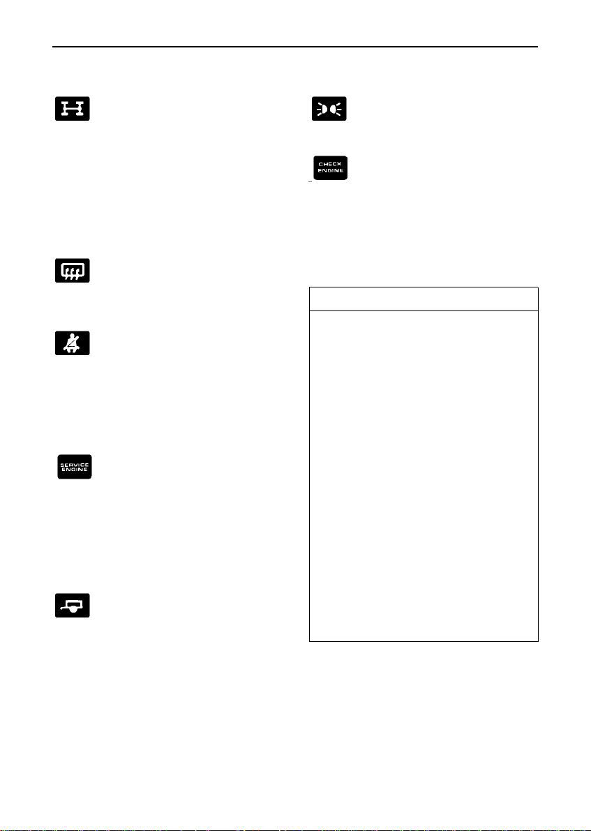
Differential lock - AMBER
Illuminates whenever the
differential lock is engaged.
If the light remains on after the differential
lock is disengaged, transmission ’wind up’
may be present. Reversing for a short
distance and then going forward will usually
’unwind’ the transmission. If the light remains
on, contact your dealer as soon as possible.
Heated rear screen - AMBER
(if fitted)
Illuminates when the rear screen
heater is operating.
Seat belt warning - RED
If the driver’s seat belt is not
fastened, the light illuminates
when the starter switch is turned to position
’II’. The light extinguishes as soon as the
driver’s seat belt is fastened. ALWAYS fasten
your seat belt BEFORE driving!
Emission maintenance reminder
- RED
Illuminates as a bulb check when
the starter switch is turned to position ’II’. If
the light illuminates at any other time, the
vehicle should be taken to your Land Rover
dealer for a special emission related service to
be carried out.
Trailer direction indicators -
GREEN
Flashes in conjunction with the
vehicle direction indicator lights to show that
all trailer indicator lights are functioning
correctly. In the event of a bulb failure on the
trailer, the warning light flashes once and then
remains off.
Side lights - GREEN
Illuminates whenever the side
lights are on.
Check engine - AMBER
Illuminates momentarily as a
bulb check when the starter
switch is turned to position ’II’ and should
extinguish when the engine is running.
Illumination at any other time, indicatesan
engine fault - if the light flashes, reduce speed
and seek qualified assistance urgently.
IMPORTANT INFORMATION
AUDIBLE WARNINGS
Driver’s seat belt reminder
A chime will sound for up to 8 seconds, if
the starter switch is turned to position ’II’,
when the driver’s seat belt is unfastened.
Starter key warning
A chime will sound if the key is left in the
starter switch, with the switch in position
’I’ or ’0’, when the driver’s door is
opened.
Lights on warning
A chime will sound if the lights are left on
when a front door is opened.
Transfer box warning
A warning chime will sound whenever the
transfer box gear lever is in the neutral
position.
NOTE: When a trailer is not fitted, the
warning light will only flash once.
19

Lights & indicators
Direction indicators
Move the lever DOWN to indicate a LEFT turn,
and UP to indicate a RIGHT turn (the GREEN
warning light on the instrument panel will
flash in time with the direction indicators).
Hold the lever part-way up or down against
spring pressure to indicate a lane change.
Main light switch
Lever position;
• Static - all lights off
• First position - parking, tail and instrument
panel lights on
• Second position - headlights on
Headlight high beam and ’flash’
With the headlights switched on, push the
lever away from the steering wheel to activate
high beam (BLUE warning light illuminates).
To flash the headlights, pull the lever part-way
towards the steering wheel and then release.
Horn
Press end of the lever to operate the horn.
20

Wipers & washers
WARNING
To prevent possible overload damage to the
linkage or the wiper motors in either
freezing or extremely hot conditions, care
must be taken to ensure that the wiper
blades are not adhering to the glass before
operating the wipers.
NOTE: Ensure an approved screen washer
solvent is used in the windscreen washer
reservoir,to prevent freezing.
WINDSCREEN WIPERS
• Single wipe
Push the lever up against spring pressure
and release immediately.
NOTE: With the lever held up, the wipers will
continue operating at high speed until it is
released.
• Intermittent wipe
Pull lever down.
• Normal speed wipe
Push lever up to first position.
• Fast speed wipe
Push lever up to second position.
• Windscreen washer
Press to operate (the wipers will also
operate).
21

Wipers & washers
IMPORTANT INFORMATION
• DO NOT operate the wipers on a dry
screen.
• In freezing or very hot conditions,
ensure that the blades are not
frozen, or stuck to the glass.
• In winter, remove any snow or ice
from around the arms and blades,
including the wiped area of the
windscreen and the heater air
intakes.
Rear window wiper & washer (if fitted)
The rear window wiper and washer only
operate with the starter switch turned to
position ’II’.
• Press the switch (1) to operate the wiper,
press again to switch off.
• Press and hold the switch (2) to operate
the washer and wiper for the required
duration. The wiper will operate four times
after the switch is released.
NOTE: If the wiper blades have stuck to
the glass, a thermal cut-out may
temporarily prevent the wiper motor from
operating. If this is the case, switch the
wipers off, free them from the
obstruction and then switch on again.
22

Switches
Rear window heater (3) (if fitted)
Press to operate, press a second time to
switch off. The warning light on the
instrument panel illuminates while the heating
elements are switched on and extinguishes
when they are turned off.
After 15 minutes continuous operation, the
heater switches off automatically.
Instrument illumination switch
With the headlights or sidelights turned on,
press the upper portion of the switch to
achieve a low level of illumination and press
the lower portion of the switch to illuminate
the instrument panel fully.
WARNING
DO NOT stick labels over the heating
elements and DO NOT scrape, or use
abrasive materials, to clean the inside of
the rear window.
Hazard warning lights (1)
Press the switch once to operate; all the
direction indicator lights (including those
fitted to a trailer) and warning lights will flash
in conjunction with each other.
Use ONLY in an emergency to warn other
road users when your stationary vehicle is
causing an obstruction, or is in a hazardous
situation. Switch off by pressing the switch
again before moving away.
23

Windows
WINDOWS
Front windows: (Station wagons)
Raise or lower the window by rotating the
handle mounted on the door.
Sliding rear windows: (Station wagons)
To open, press the catch tongues together,
slide the window to the desired position and
release the catch, ensuring that it locates
securely in the sockets, locking the window in
position.
Sliding front windows: (Soft top)
Push the lever down to unlock the window
and slide the window open as required. Push
the lever up to lock the window.
24

Sunroof
SUNROOF (if fitted)
The sunroof can be opened or, if required, can
be removed completely.
To OPEN the roof:
Turn the hand wheel counter-clockwise to give
the desired opening.
NOTE: A partially open sunroof may vibrate
due to aerodynamic pressures. Adjust the
sunroof aperture to reduce vibration.
To CLOSE the roof:
Turn the hand wheel clockwise until resistance
is felt.
Remove the sunroof by tilting upwards and
lifting rearwards to disengage the locating
lugs.
WARNING
DO NOT store the sunroof loose in the
vehicle.
DO NOT allow passengers to extend any part
of their bodies through the sunroof while the
vehicle is moving.
DO NOT remove the sunroof whilst the
vehicle is moving.
To REMOVE the roof:
Open the sunroof fully and push the catch (1)
rearwards to disengage the hand wheel
mechanism.
Refit the sunroof by following the same
procedure in reverse.
25

Heating & ventilation
Fresh air vents
To open the two vents in the windscreen
frame, push the lever to the right and then
downwards to the desired position and
release.
The temperature of air supplied to the fresh air
vents is not controlled by the heater.
26

Heating & ventilation
HEATER CONTROLS
1. Fan speed control
With the control at ’0’, the fan is switched
off and no air will enter the vehicle
through the heater vents. With the control
moved downwards to the first position,
the volume of air entering the passenger
compartment is solely dependent upon the
ram effect of the vehicle moving through
the air. The subsequent positions operate
the fan at speeds ’1’ and ’2’ respectively.
2. Temperature control
Move the lever downwards (towards the
RED segment) to increase air temperature,
or upwards (towards the BLUE segment)
to reduce air temperature.
3. Air distribution control
• Lever fully up - windscreen vents only.
• Lever midway - foot level and windscreen
vents.
• Lever fully down - foot level vents (also
provides some air to the windscreen).
27

Heating & ventilation
USING YOUR HEATER
Ensure the front grille and the air intake grille
on the front wing are kept clear of
obstructions (especially snow and ice).
The following examples of basic heater
settings are intended as a general guide; the
air distribution, temperature and blower
controls can then be further adjusted to suit
your comfort requirements.
Always remember that full heating is not
availableuntil the engine has reached its
normal operating temperature.
Maximum heating
• Temperature control - fully down.
• Distribution control - midway.
• Fan speed control - fully down.
• Fresh air vents - fully closed.
Demisting and defrosting
• Temperature control - fully down.
• Distribution control - fully up.
• Fan speed control - fully down.
• Fresh air vents - fully open for demisting
(closed for defrosting).
• Opening a window may improve
ventilation.
Maximum ventilation
• Temperature control - fully up.
• Distribution control - fully down.
• Fan speed control - fully down.
• Fresh air vents - fully open.
28

Air conditioning
USING THE AIR CONDITIONING (if fitted)
If your vehicle has been fitted with an air
conditioning system, you may find the
following guidelines useful.
Air conditioning provides additional cooling to
the vehicle interior and also reduces the
moisture content of the air.
The air conditioning system will only operate
with the fan switched on and the engine
running. It is also important to keep the
windows closed during operation.
Operation of the air conditioning system,
places an additional load on the engine which,
in very hot conditions and if the engine is
required to work unusually hard, could result
in high engine temperatures. If the
temperature gauge pointer reaches the RED
zone, turn the air conditioning off until engine
temperature returns to normal.
Points to remember:
• If the temperature inside the vehicle is
higher than that outside when you start
the engine, it will take time for the air
conditioning to become fully effective. It is
best to ventilate the vehicle by opening the
windows and operating the fan for a brief
period before switching on the air
conditioning. Remember to close the
windows whenever the air conditioning is
operating.
• Operating the air conditioning takes power
from the engine and consequently
increasesfuel consumption.
• All air conditioning systems need to be
operated for a short while every week
(even in winter) to maintain them in peak
condition.
• The air conditioning system will also
dehumidify air. The surplus water
produced by this process is expelled from
the system via drain tubes beneath the
vehicle. This may result in a small pool of
water forming on the road when the
vehicle is stationary and is not a cause for
concern.
29

Interior equipment
INTERIOR LIGHT
Station wagons:
With the switch midway between the ’ON’ and
’OFF’ positions, the light will illuminate
whenever a door is opened.
CIGAR LIGHTER (1)
With the starter switch turned to position ’II’,
press the lighter in to heat up. When it has
reached the correct temperature it will partially
eject and can then be withdrawn for use.
• ONLY hold the cigar lighter by the handle.
• DO NOT use the ashtray for disposing of
waste paper or other combustible
materials.
• DO NOT plug accessories into the cigar
lighter socket unless they are approved for
use in your vehicle by Land Rover.
CLOCK (2)
To adjust the time, press and turn the button
in the bottom right hand corner of the clock
face.
NOTE: The clock will need to be reset, if the
battery is disconnected.
30
Interior equipment
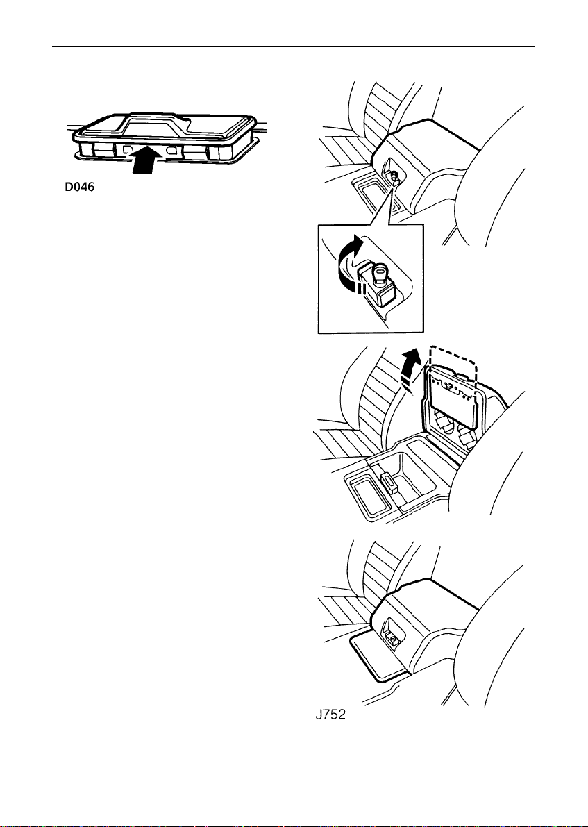
ASHTRAY
Lift the lid of the ashtray to open. To remove,
carefully prise the ashtray out of the fascia
panel.
CUBBY BOX
Turn the key clockwise to unlock the cubby
box, then squeeze the catch to open. Turn the
key counter-clockwiseto lock the box.
The flap on the underside of the cubby box lid,
can be folded out and, when the lid is shut,
acts as a security cover for the in-car
entertainment unit. It is recommended that the
security cover is used (and the cubby box
locked) whenever the vehicle is left
unattended.
NOTE: The two recesses to the side of the
gear selector are for cups or drink cans.
31

SECTION 3
Driving & operating
Section Contents Page
Starter switch & steering lock 35....................
Starting & driving 36......................................
Catalytic converter 40.....................................
Fuel 42............................................................
Gearbox & transmission 44............................
Brakes 51.......................................................
Towing & load carrying 53.............................
Emergency starting 56....................................
Vehicle recovery 58........................................
Canopy removal & fitting 60...........................
Ancillary equipment 67...................................
33

Starter switch & steering lock
To unlock the steering column
Insert the ignition key FULLY and turn the
starter switch to position ’I’, while turning the
steering wheel slightly to disengage the lock.
To lock the steering column
With the main gearshift in ’P’ and either High
or Low selected in the transfer box, turn the
starter switch to position ’0’ and withdraw the
key from the starter switch. Turn the steering
wheel towards the straight ahead position
until the lock engages.
NOTE: The starter key can NOT be turned to
position ’0’, unless the main gear selector is in
the ’P’ (Park) position and either High or Low
range is selected in the transfer gearbox.
STARTER SWITCH
The starter switch is located to the left of the
steering column, and uses the following
sequence of key positions to operate the
steering lock, electrical circuits and starter
motor.
Position ’0’
Steering locked (if key is removed).
Ignition key locked in position unless the
gearshift is in ’P’.
Most lighting circuits are operational,
including: sidelights, headlights and hazard
warning lights.
Position ’I’
Steering unlocked.
Radio/cassette/CDplayer can be operated.
Position ’II’
All instruments, warning lights and electrical
circuits are operational.
Position ’III’
Starter motor operates.
Release the key immediately the engine starts
(the key will automatically return to position
’II’).
Note that operation of position ’I’ electrical
functions will be interrupted during engine
cranking.
NOTE: The engine will not start unless ’P’ is
selected in the main gearbox and either High
or Low range is selected in the transfer
gearbox.
35
 Loading...