


1689 Rover 214 & 414 Updated Version 09/97
Rover 214 & 414
Service and Repair Manual
Mark Coombs and Christopher Rogers
Models covered
Rover 214 and 414 models fitted with eight or sixteen-valve 1397 cc ‘K-series’ engine
Covers major mechanical features of Cabriolet
Does not cover Diesel engine models
(1689-288-9AA3)
© Haynes Publishing 1997
A book in the Haynes Service and Repair Manual Series
All rights reserved. No part of this book may be reproduced or transmitted
in any form or by any means, electronic or mechanical, including
photocopying, recording or by any information storage or retrieval system,
without permission in writing from the copyright holder.
ISBN 1 85960 458 7
British Library Cataloguing in Publication Data
A catalogue record for this book is available from the British Library.
Printed by J H Haynes & Co. Ltd, Sparkford, Nr Yeovil,
Somerset BA22 7JJ
Haynes Publishing
Sparkford, Nr Yeovil, Somerset BA22 7JJ, England
Haynes North America, Inc
861 Lawrence Drive, Newbury Park, California 91320, USA
Editions Haynes S.A.
147/149, rue Saint Honoré, 75001 PARIS, France
Haynes Publishing Nordiska AB
Fyrisborgsgatan 5, 754 50 Uppsala, Sverige

1689 Rover 214 & 414 Updated Version 09/97
LIVING WITH YOUR ROVER 214 & 414
Introduction Page 0•4
Safety First! Page 0•5
Roadside Repairs
Introduction Page 0•6
If your car won’t start Page 0•6
Jump starting Page 0•7
Wheel changing Page 0•8
Identifying leaks Page 0•9
Towing Page 0•9
Weekly Checks
Introduction Page 0•10
Underbonnet check points Page 0•10
Engine oil level Page 0•11
Coolant level Page 0•11
Brake fluid level Page 0•12
Screen washer fluid level Page 0•12
Power steering fluid level Page 0•13
Wiper blades Page 0•13
Tyre condition and pressure Page 0•14
Electrical systems Page 0•15
Battery Page 0•15
Lubricants, Fluids, Capacities and Tyre Pressures Page 0•16
MAINTENANCE
Routine Maintenance and Servicing Page 1•1
Maintenance schedule Page 1•3
Maintenance procedures Page 1•6
Contents

1689 Rover 214 & 414 Updated Version 09/97
REPAIRS AND OVERHAUL
Engine and Associated Systems
Engine in-car repair procedures Page 2A•1
Engine removal and general overhaul procedures Page 2B•1
Cooling, heating and ventilation systems Page 3•1
Fuel and exhaust systems - carburettor engines Page 4A•1
Fuel and exhaust systems - single-point fuel injected engines Page 4B•1
Fuel and exhaust systems - multi-point fuel injected engines Page 4C•1
Emission control systems Page 4D•1
Ignition system - carburettor engines Page 5A•1
Ignition system - fuel injected engines Page 5B•1
Starting and charging systems Page 5C•1
Transmission
Clutch Page 6•1
Gearbox Page 7•1
Driveshafts Page 8•1
Brakes and Suspension
Braking system Page 9•1
Suspension and steering Page 10•1
Body Equipment
Bodywork and fittings Page 11•1
Body electrical systems Page 12•1
Wiring Diagrams Page 12•20
REFERENCE
Dimensions and Weights Page REF•1
Conversion Factors Page REF•2
Buying Spare Parts and Vehicle Identification Page REF•3
General Repair Procedures Page REF•4
Jacking and Vehicle Support Page REF•5
Radio/cassette Anti-theft System - precaution Page REF•5
Tools and Working Facilities Page REF•6
MOT Test Checks Page REF•8
Fault Finding Page REF•12
Glossary of Technical Terms Page REF•19
Index Page REF•24
Contents

1689 Rover 214 & 414 Updated Version 09/97
0•4
The Rover 214 Hatchback and 414 Saloon
models covered in this Manual are a muchdeveloped version of the original 213 and 216
models first launched in 1984. The 214 five-door
model was the first to be introduced in October
1989 and was closely followed by the
414 model introduced in March 1990. The 214
model range was further updated in September
1990 when a three-door variant was introduced.
All models are fitted with the new 1.4 litre
‘K’ series engine. The 214 S model (first
introduced in September 1990) has an eightvalve single overhead camshaft version of the
engine which is fed by an SU KIF carburettor.
All other 214 and 414 models are equipped
with a sixteen-valve double overhead
camshaft version of the engine which is
controlled by a Rover/Motorola Modular
Engine Management System (MEMS) with
either single-point fuel injection (SPi) or multipoint fuel injection (MPi). All versions of the
engine are able to accept a full range of
emission control systems, up to and including
a three-way regulated catalytic converter.
The five-speed transmission, which is a
joint development by Rover and Peugeot
engineers, is of Peugeot design and produced
by Rover. The transmission is fitted to the left-
hand end of the engine. The complete
engine/transmission unit is mounted
transversely across the front of the car and
drives the front wheels through unequallength driveshafts.
The front suspension incorporates
MacPherson struts and the rear is of the
double wishbone type.
Braking is by discs at the front and drums
at the rear, with a dual-circuit hydraulic
system. On all models in the range, an Antilock Braking System (ABS) was offered as an
optional extra. If ABS is fitted, then braking is
by discs both at the front and rear.
Rover 114GTa Rover Metro 1.1S
Introduction
Acknowledgements
The aim of this manual is to help you get
the best value from your vehicle. It can do so
in several ways. It can help you decide what
work must be done (even should you choose
to get it done by a garage), provide
information on routine maintenance and
servicing, and give a logical course of action
and diagnosis when random faults occur.
However, it is hoped that you will use the
manual by tackling the work yourself. On
simpler jobs it may even be quicker than
booking the car into a garage and going there
twice, to leave and collect it. Perhaps most
important, a lot of money can be saved by
avoiding the costs a garage must charge to
cover its labour and overheads.
The manual has drawings and descriptions
to show the function of the various components
so that their layout can be understood. Then
the tasks are described and photographed in a
clear step-by-step sequence.
Your Rover 214 & 414 Manual
Thanks are due to Champion Spark Plug
who supplied the illustrations showing spark
plug conditions, and to Duckhams Oils who
provided lubrication data. Thanks are also
due to Sykes-Pickavant Limited, who
supplied some of the workshop tools, and to
all those people at Sparkford who helped in
the production of this Manual.
We take great pride in the accuracy of
information given in this manual, but
vehicle manufacturers make alterations
and design changes during the production
run of a particular vehicle of which they
do not inform us. No liability can be
accepted by the authors or publishers for
loss, damage or injury caused by any
errors in, or omissions from the
information given.

1689 Rover 214 & 414 Updated Version 09/97
0•5
Safety First!
Working on your car can be dangerous.
This page shows just some of the potential
risks and hazards, with the aim of creating a
safety-conscious attitude.
General hazards
Scalding
• Don’t remove the radiator or expansion
tank cap while the engine is hot.
• Engine oil, automatic transmission fluid or
power steering fluid may also be dangerously
hot if the engine has recently been running.
Burning
• Beware of burns from the exhaust system
and from any part of the engine. Brake discs
and drums can also be extremely hot
immediately after use.
Crushing
• When working under or near
a raised vehicle,
always
supplement the
jack with axle
stands, or use
drive-on
ramps.
Never
venture
under a car which
is only supported by a jack.
• Take care if loosening or tightening hightorque nuts when the vehicle is on stands.
Initial loosening and final tightening should
be done with the wheels on the ground.
Fire
• Fuel is highly flammable; fuel vapour is
explosive.
• Don’t let fuel spill onto a hot engine.
• Do not smoke or allow naked lights
(including pilot lights) anywhere near a
vehicle being worked on. Also beware of
creating sparks
(electrically or by use of tools).
• Fuel vapour is heavier than air, so don’t
work on the fuel system with the vehicle over
an inspection pit.
• Another cause of fire is an electrical
overload or short-circuit. Take care when
repairing or modifying the vehicle wiring.
• Keep a fire extinguisher handy, of a type
suitable for use on fuel and electrical fires.
Electric shock
• Ignition HT
voltage can be
dangerous,
especially to
people with heart
problems or a
pacemaker. Don’t
work on or near the
ignition system with
the engine running or
the ignition switched on.
• Mains voltage is also dangerous. Make
sure that any mains-operated equipment is
correctly earthed. Mains power points should
be protected by a residual current device
(RCD) circuit breaker.
Fume or gas intoxication
• Exhaust fumes are
poisonous; they often
contain carbon
monoxide, which is
rapidly fatal if inhaled.
Never run the
engine in a
confined space
such as a garage
with the doors shut.
• Fuel vapour is also
poisonous, as are the vapours from some
cleaning solvents and paint thinners.
Poisonous or irritant substances
• Avoid skin contact with battery acid and
with any fuel, fluid or lubricant, especially
antifreeze, brake hydraulic fluid and Diesel
fuel. Don’t syphon them by mouth. If such a
substance is swallowed or gets into the eyes,
seek medical advice.
• Prolonged contact with used engine oil can
cause skin cancer. Wear gloves or use a
barrier cream if necessary. Change out of oilsoaked clothes and do not keep oily rags in
your pocket.
• Air conditioning refrigerant forms a
poisonous gas if exposed to a naked flame
(including a cigarette). It can also cause skin
burns on contact.
Asbestos
• Asbestos dust can cause cancer if inhaled
or swallowed. Asbestos may be found in
gaskets and in brake and clutch linings.
When dealing with such components it is
safest to assume that they contain asbestos.
Special hazards
Hydrofluoric acid
• This extremely corrosive acid is formed
when certain types of synthetic rubber, found
in some O-rings, oil seals, fuel hoses etc, are
exposed to temperatures above 4000C. The
rubber changes into a charred or sticky
substance containing the acid. Once formed,
the acid remains dangerous for years. If it
gets onto the skin, it may be necessary to
amputate the limb concerned.
• When dealing with a vehicle which has
suffered a fire, or with components salvaged
from such a vehicle, wear protective gloves
and discard them after use.
The battery
• Batteries contain sulphuric acid, which
attacks clothing, eyes and skin. Take care
when topping-up or carrying the battery.
• The hydrogen gas given off by the battery
is highly explosive. Never cause a spark or
allow a naked light nearby. Be careful when
connecting and disconnecting battery
chargers or jump leads.
Air bags
• Air bags can cause injury if they go off
accidentally. Take care when removing the
steering wheel and/or facia. Special storage
instructions may apply.
Diesel injection equipment
• Diesel injection pumps supply fuel at very
high pressure. Take care when working on
the fuel injectors and fuel pipes.
Warning: Never expose the hands,
face or any other part of the body
to injector spray; the fuel can
penetrate the skin with potentially fatal
results.
Remember...
DO
• Do use eye protection when using power
tools, and when working under the vehicle.
• Do wear gloves or use barrier cream to
protect your hands when necessary.
• Do get someone to check periodically
that all is well when working alone on the
vehicle.
• Do keep loose clothing and long hair well
out of the way of moving mechanical parts.
• Do remove rings, wristwatch etc, before
working on the vehicle – especially the
electrical system.
• Do ensure that any lifting or jacking
equipment has a safe working load rating
adequate for the job.
A few tips
DON’T
• Don’t attempt to lift a heavy component
which may be beyond your capability – get
assistance.
• Don’t rush to finish a job, or take
unverified short cuts.
• Don’t use ill-fitting tools which may slip
and cause injury.
• Don’t leave tools or parts lying around
where someone can trip over them. Mop
up oil and fuel spills at once.
• Don’t allow children or pets to play in or
near a vehicle being worked on.

1689 Rover 214 & 414 Updated Version 09/97
0•6
Roadside repairs
The following pages are intended to help in dealing with
common roadside emergencies and breakdowns. You will find
more detailed fault finding information at the back of the
manual, and repair information in the main chapters.
If your car won’t start
and the starter motor
doesn’t turn
M If it’s a model with automatic transmission, make sure the
selector is in ‘P’ or ‘N’.
M Open the bonnet and make sure that the battery terminals
are clean and tight.
M Switch on the headlights and try to start the engine. If the
headlights go very dim when you’re trying to start, the
battery is probably flat. Get out of trouble by jump starting
(see next page) using a friend’s car.
If your car won’t start
even though the starter
motor turns as normal
M Is there fuel in the tank?
M Is there moisture on electrical components under the
bonnet? Switch off the ignition, then wipe off any obvious
dampness with a dry cloth. Spray a water-repellent aerosol
product (WD-40 or equivalent) on ignition and fuel system
electrical connectors like those shown in the photos.
Pay special attention to the ignition coil wiring connector
and HT leads. (Note that Diesel engines don’t normally
suffer from damp.)
Check that the distributor HT lead
connections are clean and secure
A
Check that the spark plug HT lead
connections are clean and secure cover removed
B
Check that the ignition coil HT and LT
lead connections are clean and secure
C
Check the security and condition of the
battery connections
D
The ECU wiring plugs may cause
problems if dirty or not properly
connected
E
Check that electrical connections are secure (with the ignition off) and spray them with a waterdispersing spray like WD40 if you suspect a problem due to damp

0•7
1689 Rover 214 & 414 Updated Version 09/97
Roadside repairs
When jump-starting a car using a
booster battery, observe the following
precautions:
4 Before connecting the booster
battery, make sure that the ignition
is switched off.
4 Ensure that all electrical equipment
(lights, heater, wipers, etc) is
switched off.
4 Take note of any special precautions
printed on the battery case.
4 Make sure that the booster battery
is the same voltage as the
discharged one in the vehicle.
4 If the battery is being jump-started
from the battery in another vehicle,
the two vehicles MUST NOT TOUCH
each other.
4 Make sure that the transmission is in
neutral (or PARK, in the case of
automatic transmission).
Jump starting will get you
out of trouble, but you must
correct whatever made the
battery go flat in the first
place. There are three possibilities:
1) The battery has been drained by
repeated attempts to start, or by
leaving the lights on.
2) The charging system is not working
properly (alternator drivebelt slack or
broken, alternator wiring fault or
alternator itself faulty).
3) The battery itself is at fault (electrolyte
low, or battery worn out).
Connect one end of the red jump lead
to the positive (+) terminal of the flat
battery
Connect the other end of the red lead
to the positive (+) terminal of the
booster battery
Connect one end of the black jump lead
to the negative (-) terminal of the
booster battery
Connect the other end of the black
jump lead to a bolt or bracket on the
engine block, well away from the
battery, on the vehicle to be started
1 2 3
4
Make sure that the jump leads will not
come into contact with the fan,
drivebelts or other moving parts of the
engine
5
Start the engine using the booster
battery, then with the engine running at
idle speed, disconnect the jump leads
in the reverse order of connection
6
Jump starting

1689 Rover 214 & 414 Updated Version 09/97
0•8
Roadside repairs
Location of spare wheel and tools in boot
Wheel changing
Some of the details shown here will vary
according to model. For instance, the location
of the spare wheel and jack is not the same
on all cars. However, the basic principles
apply to all vehicles.
Warning: Do not change a wheel in a situation where you risk being hit by
other traffic. On busy roads, try to stop in a lay-by or a gateway. Be wary of
passing traffic while changing the wheel – it is easy to become distracted by
the job in hand.
Finally...
M Remove the wheel chocks.
M Stow the jack and tools in the correct
locations in the car.
M
Check the tyre pressure on the wheel just
fitted. If it is low, or if you don’t have a
pressure gauge with you, drive slowly to
the nearest garage and inflate the tyre to
the right pressure.
M Have the damaged tyre or wheel repaired
as soon as possible.
Use the wheel brace to slightly loosen the
wheelnuts
Locate the jack head in the correct
jacking point
Raise the jack until the wheel is clear of
the ground
Remove the trim to expose the wheelnutsUnscrew the spare wheel retaining cap
1
2
3
4
5
Remove the wheelnuts and lift off the
wheel
7
Fit the replacement wheel and tighten the
nuts
8
6
Preparation
M When a puncture occurs, stop as soon as
it is safe to do so.
M Park on firm level ground, if possible,
and well out of the way of other traffic.
M Use hazard warning lights if necessary.
M If you have one, use a warning triangle to
alert other drivers of your presence.
M Apply the handbrake and engage first or
reverse gear (or Park on models with
automatic transmission).
M Chock the wheel diagonally opposite the
one being removed – a couple of large
stones will do for this.
M If the ground is soft, use a flat piece of
wood to spread the load under the jack.
Changing the wheel
1689 Rover 214 & 414 Updated Version 09/97
0•9
Roadside repairs
Towing
Puddles on the garage floor or drive, or
obvious wetness under the bonnet or
underneath the car, suggest a leak that needs
investigating. It can sometimes be difficult to
decide where the leak is coming from,
especially if the engine bay is very dirty
already. Leaking oil or fluid can also be blown
rearwards by the passage of air under the car,
giving a false impression of where the
problem lies.
Warning: Most automotive oils
and fluids are poisonous. Wash
them off skin, and change out of
contaminated clothing, without
delay.
Identifying leaks
The smell of a fluid leaking
from the car may provide a
clue to what’s leaking. Some
fluids are distinctively
coloured. It may help to clean the car
carefully and to park it over some clean
paper overnight as an aid to locating the
source of the leak.
Remember that some leaks may only
occur while the engine is running.
When all else fails, you may find yourself
having to get a tow home – or of course you
may be helping somebody else. Long-distance
recovery should only be done by a garage or
breakdown service. For shorter distances, DIY
towing using another car is easy enough, but
observe the following points:
M Use a proper tow-rope – they are not
expensive. The vehicle being towed must
display an ‘ON TOW’ sign in its rear window.
M Always turn the ignition key to the ‘on’
position when the vehicle is being towed, so
that the steering lock is released, and that the
direction indicator and brake lights will work.
M Only attach the tow-rope to the towing
eyes provided.
M Before being towed, release the handbrake
and select neutral on the transmission.
M Note that greater-than-usual pedal
pressure will be required to operate the
brakes, since the vacuum servo unit is only
operational with the engine running.
M On models with power steering, greaterthan-usual steering effort will also be required.
M The driver of the car being towed must
keep the tow-rope taut at all times to avoid
snatching.
M Make sure that both drivers know the route
before setting off.
M Only drive at moderate speeds and keep
the distance towed to a minimum. Drive
smoothly and allow plenty of time for slowing
down at junctions.
M On models with automatic transmission,
special precautions apply. If in doubt, do not
tow, or transmission damage may result.
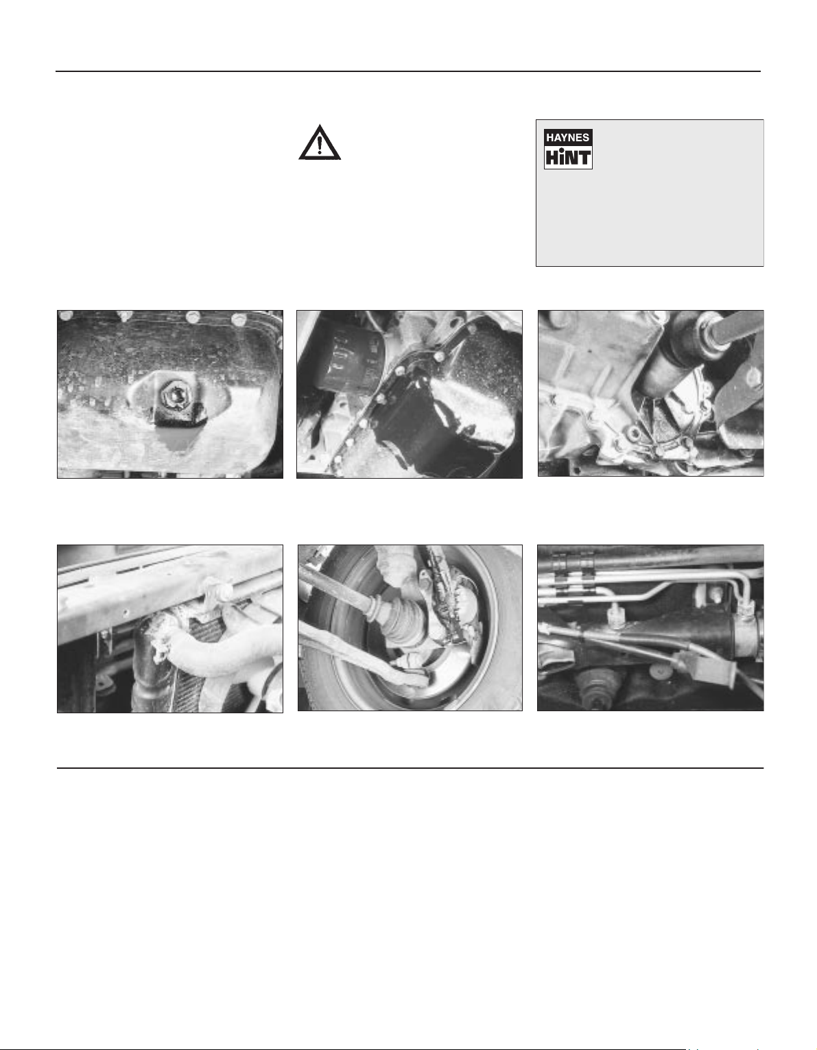
Sump oil Gearbox oil
Brake fluid Power steering fluid
Oil from filter
Antifreeze
Engine oil may leak from the drain plug... ...or from the base of the oil filter.
Leaking antifreeze often leaves a crystalline
deposit like this.
Gearbox oil can leak from the seals at the
inboard ends of the driveshafts.
A leak occurring at a wheel is almost
certainly brake fluid.
Power steering fluid may leak from the pipe
connectors on the steering rack.

1689 Rover 214 & 414 Updated Version 09/97
0•10
There are some very simple checks which
need only take a few minutes to carry out, but
which could save you a lot on inconvenience
and expense.
These “Weekly Checks” require no great skill
or special tools, and the small amount of time
they take to perform could well prove to be
very well spent, for example:
mm Keeping an eye on tyre condition and
pressures, will not only help to stop them
wearing out prematurely but could also save
your life.
mm Many breakdowns are caused by electrical
problems. Battery-related faults are particularly
common and a quick check on a regular basis
will often prevent the majority of these.
mm If your car develops a brake fluid leak, the
first time you might know about it is when
your brakes don’t work properly. Checking
the level regularly will give advance warning of
this kind of problem.
mm If the oil or coolant levels run low, the cost
of repairing any engine damage will be far
greater than fixing the leak.
Underbonnet Check Points
K16 MPi engine with plastic inlet manifold
Introduction
Weekly checks
A
Engine oil level dipstick
B
Engine oil filler cap
C
Coolant expansion tank
D
Brake fluid reservoir
E
Power steering fluid reservoir
F
Screen washer fluid reservoir
G
Battery

1689 Rover 214 & 414 Updated Version 09/97
0•11
Weekly checks
Engine oil level
Before you start
4 Make sure that your car is on level ground.
4 Check the oil level before the car is driven,
or at least 5 minutes after the engine has been
switched off.
The correct oil
Modern engines place great demands on their
oil. It is very important that the correct oil for
your car is used (see “Lubricants and Fluids”
on page 0•16).
Car Care
l If you have to add oil frequently, you should
check whether you have any oil leaks. Place
some clean paper under the car overnight,
and check for stains in the morning. If there
are no leaks, then engine may be burning oil
(see “Fault Finding”).
l Always maintain the level between the
upper and lower dipstick marks. If the level is
too low, severe engine damage may occur. Oil
seal failure may result if the engine is overfilled
by adding too much oil.
Using a clean rag or paper towel, wipe all
the oil from the dipstick. Insert the clean
dipstick into the tube as far as it will go, then
withdraw it again.
Note the oil level on the end of the
dipstick, which should be between the
upper HI mark and the lower LO mark.
Approximately 1.0 litre of oil will raise the level
from the lower mark to the upper mark.
Oil is added through the filler cap. Rotate
the cap through a quarter-turn anticlockwise and withdraw it. Top-up the level. A
funnel may help to reduce spillage. Add the oil
slowly, checking the level on the dipstick
often. Do not overfill.
The dipstick is located at the rear right-hand
end of the engine (see “Underbonnet Check
Points” on page 0•10 for exact location).
Withdraw the dipstick.
1 2
3 4
If the oil is checked
immediately after driving the
vehicle, some of the oil will
remain in the upper engine
components, resulting in an inaccurate
reading on the dipstick.
Coolant level
Add a mixture of water and antifreeze
through the expansion tank filler neck,
until the coolant is up to the upper level. Refit
the cap, turning it clockwise as far as it will go
until it is secure.
If topping-up, wait until the engine is
cold, then cover the filler cap with a layer
of rag and start unscrewing the cap. Wait until
any hissing ceases, indicating that all
pressure is released, then slowly unscrew the
cap until it can be removed. At all times keep
well away from the filler opening.
When the engine is cold, the coolant level
should be between the expansion tank
ridge/seam and the level indicated above
COOLANT LEVEL on the side of the
expansion tank, which is located in the front
right-hand corner of the engine compartment.
1 2 3
Warning: Do not attempt to
remove the expansion tank
pressure cap when the engine is
hot, as there is a very great risk
of scalding. Do not leave open containers
of coolant about, as it is poisonous.
Car Care
l With a sealed-type cooling system, adding
coolant should not be necessary on a regular
basis. If frequent topping-up is required, it is
likely there is a leak. Check the radiator, all
hoses and joint faces for signs of staining or
wetness, and rectify as necessary.
l It is important that antifreeze is used in the
cooling system all year round, not just during
the winter months. Don’t top up with water
alone, as the antifreeze will become diluted.
1689 Rover 214 & 414 Updated Version 09/97
Warning: Brake fluid can harm
your eyes and damage painted
surfaces, so use extreme
caution when handling and
pouring it. Do not use fluid which has
been standing open for some time, as it
absorbs moisture from the air, which can
cause a dangerous loss of braking
effectiveness.
Before you start
4 Make sure that the car is on level ground.
4 Cleanliness is of great importance when
dealing with the braking system, so take
care to clean around the reservoir cap
before topping-up. Use only clean brake fluid
from a container which has stood for at least
24 hours (to allow air bubbles to separate
out).
Safety first
l If the reservoir requires repeated toppingup, this is an indication of a fluid leak
somewhere in the system, which should be
investigated immediately.
l If a leak is suspected, the car should not be
driven until the braking system has been
checked. Never take any risks where brakes
are concerned.
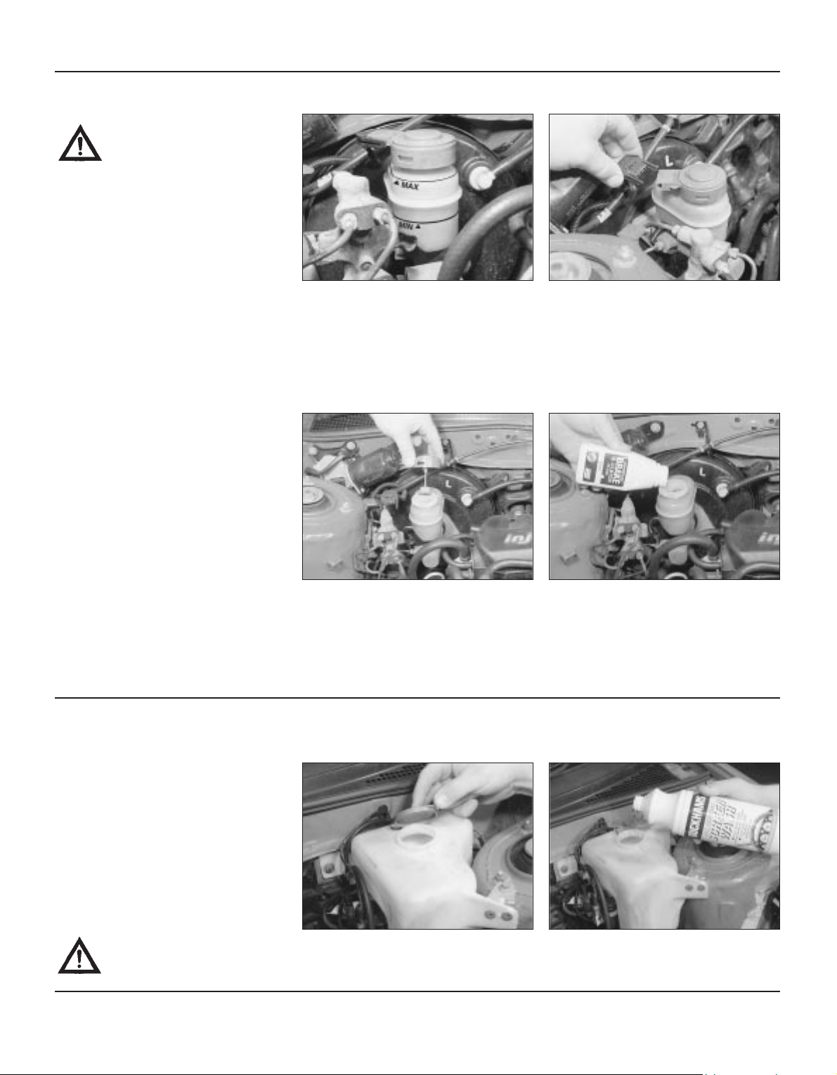
Brake fluid level
Carefully add fluid avoiding spilling it on
surrounding paintwork. Use only the
specified fluid; mixing different types can
cause damage to the system. After filling to
the correct level, refit the cap securely, to
prevent leaks and the entry of foreign matter.
Ensure that the fluid level switch plunger is
free to move. Wipe off any spilt fluid.
Before adding fluid, it’s a good idea to
inspect the reservoir. The system should
be drained and refilled if dirt is seen in the
fluid (see Chapter 9 for details).
The brake master cylinder and fluid
reservoir is mounted on the vacuum
servo unit in the engine compartment. The
MAX and MIN level marks are indicated on the
side of the reservoir and the fluid level should
be maintained between these marks at all
times.
1
If topping-up is necessary, unplug the
electrical connector and wipe the area
around the filler cap with a clean rag before
removing the cap. When adding fluid, pour it
carefully into the reservoir to avoid spilling it
on surrounding painted surfaces. Be sure to
use only the specified brake hydraulic fluid
since mixing different types of fluid can cause
damage to the system.
2
3 4
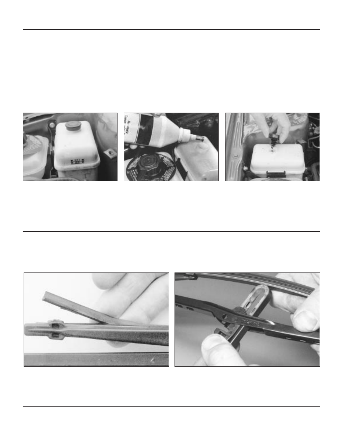
Screen washer fluid level
The reservoir for the windscreen and rear
window (where fitted) washer systems is
located on the left-hand side of the engine
compartment.
When topping-up the reservoir(s) a
screenwash additive should be added in
the quantities recommended on the bottle.
Car care
l Screenwash additives not only keep the
windscreen clean during bad weather, they
also prevent the washer system freezing in
cold weather - which is when you are likely to
need it most. Don’t top up using plain water,
as the screenwash will become diluted and
will freeze in cold weather.
l Check the operation of the windscreen and
rear window washers. Adjust the nozzles
using a pin if necessary, aiming the spray to a
point slightly above the centre of the swept
area.
Warning: On no account use
engine coolant antifreeze in the
screen washer system - this will
damage the paintwork.
1 2
0•12
Weekly checks
1689 Rover 214 & 414 Updated Version 09/97
0•13
Weekly checks
To remove a wiper blade, pull the arm fully away from the glass
until it locks. Swivel the blade through 90º, press the locking tab
with a finger nail and slide the blade out of the arm’s hooked end. On
refitting, ensure that the blade locks securely into the arm.
Check the condition of the wiper blades. If they are cracked or
show any signs of deterioration, or if the glass swept area is
smeared, renew them. For maximum clarity of vision, wiper blades
should be renewed annually, as a matter of course.
2
After filling the reservoir to the proper
level, make sure that the cap is refitted
securely to avoid leaks and the entry of
foreign matter into the reservoir.
3
If topping-up is necessary, first wipe the
area around the filler cap with a clean rag
before removing the cap. When adding fluid,
pour it carefully into the reservoir to avoid
spillage. Be sure to use only the specified
fluid.
2
The power steering fluid reservoir is
located on the right-hand side of the
engine compartment, just behind the cooling
system expansion tank. MAX and MIN level
marks are indicated on the side of the
reservoir and the fluid level should be
maintained between these marks at all times.
1
1
Wiper blades
Power steering fluid level
Before you start
4 Make sure that the car is on level ground.
4 Set the front roadwheels in the straight-
ahead position.
4 The engine should be stopped.
4 Do not operate the steering once the
engine is stopped.
Safety first
l If the reservoir requires repeated toppingup, there is a fluid leak somewhere in the
system which should be investigated
immediately.
l If a leak is suspected, the car should not be
driven until the power steering system has
been checked.

1689 Rover 214 & 414 Updated Version 09/97
0•14
Weekly checks
It is very important that tyres are in good
condition, and at the correct pressure - having
a tyre failure at any speed is highly dangerous.
Tyre wear is influenced by driving style - harsh
braking and acceleration, or fast cornering,
will all produce more rapid tyre wear. As a
general rule, the front tyres wear out faster
than the rears. Interchanging the tyres from
front to rear (“rotating” the tyres) may result in
more even wear. However, if this is
completely effective, you may have the
expense of replacing all four tyres at once!
Remove any nails or stones embedded in the
tread before they penetrate the tyre to cause
deflation. If removal of a nail does reveal that
the tyre has been punctured, refit the nail so
that its point of penetration is marked. Then
immediately change the wheel, and have the
tyre repaired by a tyre dealer.
Regularly check the tyres for damage in the
form of cuts or bulges, especially in the
sidewalls. Periodically remove the wheels,
and clean any dirt or mud from the inside and
outside surfaces. Examine the wheel rims for
signs of rusting, corrosion or other damage.
Light alloy wheels are easily damaged by
“kerbing” whilst parking; steel wheels may
also become dented or buckled. A new wheel
is very often the only way to overcome severe
damage.
New tyres should be balanced when they are
fitted, but it may become necessary to rebalance them as they wear, or if the balance
weights fitted to the wheel rim should fall off.
Unbalanced tyres will wear more quickly, as
will the steering and suspension components.
Wheel imbalance is normally signified by
vibration, particularly at a certain speed
(typically around 50 mph). If this vibration is
felt only through the steering, then it is likely
that just the front wheels need balancing. If,
however, the vibration is felt through the
whole car, the rear wheels could be out of
balance. Wheel balancing should be carried
out by a tyre dealer or garage.
Tyre Pressure Check
Check the tyre pressures regularly with
the tyres cold. Do not adjust the tyre
pressures immediately after the vehicle has
been used, or an inaccurate setting will result.
Tyre pressures are shown on page 0•16
Tread Depth - manual check
Alternatively tread wear can be
monitored with a simple, inexpensive
device known as a tread depth indicator
gauge.
Tread Depth - visual check
The original tyres have tread wear safety
bands (B), which will appear when the
tread depth reaches approximately 1.6 mm.
The band positions are indicated by a
triangular mark on the tyre sidewall (A).
1 2 3
Tyre condition and pressure
Tyre tread wear patterns
Shoulder Wear
Underinflation (wear on both sides)
Under-inflation will cause overheating of the
tyre, because the tyre will flex too much, and
the tread will not sit correctly on the road
surface. This will cause a loss of grip and
excessive wear, not to mention the danger of
sudden tyre failure due to heat build-up.
Check and adjust pressures
Incorrect wheel camber (wear on one side)
Repair or renew suspension parts
Hard cornering
Reduce speed!
Centre Wear
Overinflation
Over-inflation will cause rapid wear of the
centre part of the tyre tread, coupled with
reduced grip, harsher ride, and the danger of
shock damage occurring in the tyre casing.
Check and adjust pressures
If you sometimes have to inflate your car’s
tyres to the higher pressures specified for
maximum load or sustained high speed, don’t
forget to reduce the pressures to normal
afterwards.
Uneven Wear
Front tyres may wear unevenly as a result of
wheel misalignment. Most tyre dealers and
garages can check and adjust the wheel
alignment (or "tracking") for a modest charge.
Incorrect camber or castor
Repair or renew suspension parts
Malfunctioning suspension
Repair or renew suspension parts
Unbalanced wheel
Balance tyres
Incorrect toe setting
Adjust front wheel alignment
Note: The feathered edge of the tread which
typifies toe wear is best checked by feel.
4

1689 Rover 214 & 414 Updated Version 09/97
0•15
Weekly checks
Electrical system
If more than one indicator light or
headlight has failed, it is likely that either
a fuse has blown or that there is a fault in the
circuit (see Chapter 12).
If a single indicator light, brake light or
headlight has failed, it is likely that a bulb
has blown and will need to be replaced. Refer
to Chapter 12 for details. If both brake lights
have failed, it is possible that the brake light
switch operated by the brake pedal is faulty.
Refer to Chapter 9 for details.
1
If you need to check your
brake lights and indicators
unaided, back up to a wall or
garage door and operate the
lights. The reflected light should show if
they are working properly.
4 Check all external lights and the horn. Refer
to the appropriate Sections of Chapter 12 for
details if any of the circuits are found to be
inoperative, and replace the fuse if necessary.
Most fuses are located behind the cover in the
right-hand lower facia panel. Other fuses are
located in the fusebox on the left-hand side of
the engine compartment. To replace a blown
fuse, pull it from position, using the plastic
tool provided. Fit a new fuse of the same
rating. If a second fuse blows, it is important
that you find the reason - do not use a fuse
with a higher rating.
4 Visually check all accessible wiring
connectors, harnesses and retaining clips for
security, and for signs of chafing or damage.
2
Battery
Caution: Before carrying out any work on
the vehicle battery, read the precautions
given in “Safety first” at the start of this
manual.
4 Make sure that the battery tray is in good
condition, and that the clamp is tight.
Corrosion on the tray, retaining clamp and the
battery itself can be removed with a solution
of water and baking soda. Thoroughly rinse all
cleaned areas with water. Any metal parts
damaged by corrosion should be covered
with a zinc-based primer, then painted.
4 Periodically (approximately every three
months), check the charge condition of the
battery as described in Chapter 5A.
4 If the battery is flat, and you need to jump
start your vehicle, see “Jump starting”.
The battery is located on the left-hand
side of the engine compartment. The
exterior of the battery should be inspected
periodically for damage such as a cracked
case or cover.
Check the tightness of battery clamps to
ensure good electrical connections. You
should not be able to move them. Also check
each cable for cracks and frayed conductors.
If corrosion (white, fluffy deposits) is
evident, remove the cables from the
battery terminals, clean them with a small wire
brush, then refit them. Accessory stores sell a
useful tool for cleaning the battery post ...
1 2
3
... as well as the battery cable clamps
4
Battery corrosion can be kept to a
minimum by applying a layer of
petroleum jelly to the clamps and
terminals after they are reconnected.

1689 Rover 214 & 414 Updated Version 09/97
0•16
Lubricants, fluids, capacities and tyre pressures
Lubricants and fluids
Capacities
Tyre Pressures (tyres cold)
Engine . . . . . . . . . . . . . . . . . . . . . . . . . . . . . . . . . . . . . . . Multigrade engine oil, viscosity SAE 10W/40 to spec.
API-SG or SG/CD, CCMC G4, or RES.22.OL.G4
(Duckhams QS, QXR, Hypergrade Plus, Hypergrade, or
10W/40 Motor Oil)
Cooling system . . . . . . . . . . . . . . . . . . . . . . . . . . . . . . . . Antifreeze to spec. BS 6580 and BS 5117. Ethylene-
glycol based with non-phosphate corrosion inhibitors,
containing no methanol. Mixture 50% by volume
(Duckhams Antifreeze and Summer Coolant)
Gearbox . . . . . . . . . . . . . . . . . . . . . . . . . . . . . . . . . . . . . Special gearbox oil. Refer to your Rover dealer
(Duckhams Hypoid PT 75W/80 may be used for toppingup only)
Braking system . . . . . . . . . . . . . . . . . . . . . . . . . . . . . . . . Hydraulic fluid to spec. SAE J 1703 or DOT 4
(Duckhams Universal Brake and Clutch Fluid)
Power steering system . . . . . . . . . . . . . . . . . . . . . . . . . . . Automatic transmission fluid (ATF) to Dexron II D
specification (Duckhams Uni-Matic)
General greasing . . . . . . . . . . . . . . . . . . . . . . . . . . . . . . . Multi-purpose lithium-based grease to NLGI consistency
No. 2 (Duckhams LB10)
Engine oil . . . . . . . . . . . . . . . . . . . . . . . . . . . . . . . . . . . . 4.5 litres - including filter
Cooling system . . . . . . . . . . . . . . . . . . . . . . . . . . . . . . . . 5.8 litres
Gearbox . . . . . . . . . . . . . . . . . . . . . . . . . . . . . . . . . . . . . 2.0 litres
Power steering reservoir . . . . . . . . . . . . . . . . . . . . . . . . 1.2 litres
Fuel tank . . . . . . . . . . . . . . . . . . . . . . . . . . . . . . . . . . . . . 55 litres
Washer system reservoir . . . . . . . . . . . . . . . . . . . . . . . 3.1 litres
Front Rear
155 SR 13 tyres
Normal driving conditions . . . . . . . . . . . . . . . . . . . . . . . . 2.1 bar (30 psi) 2.1 bar (30 psi)
Loads in excess of four persons . . . . . . . . . . . . . . . . . . . 2.1 bar (30 psi) 2.3 bar (34 psi)
Speeds in excess of 100 mph - all loads . . . . . . . . . . . . . 2.2 bar (32 psi) 2.2 bar (32 psi)
175/65 TR 14 tyres
All loads - up to 100 mph . . . . . . . . . . . . . . . . . . . . . . . . . 2.1 bar (30 psi) 2.1 bar (30 psi)
All loads - over 100 mph . . . . . . . . . . . . . . . . . . . . . . . . . 2.2 bar (32 psi) 2.2 bar (32 psi)
185/60 HR 14 tyres
All loads - up to 100 mph . . . . . . . . . . . . . . . . . . . . . . . . . 2.1 bar (30 psi) 2.1 bar (30 psi)
All loads - over 100 mph . . . . . . . . . . . . . . . . . . . . . . . . . 2.5 bar (36 psi) 2.5 bar (36 psi)
Note: Pressures apply only to original equipment tyres and may vary if any other make or type is fitted. Check with
the tyre manufacturer or supplier for correct pressures if necessary

2A
1689 Rover 214 & 414 Updated Version 09/97
Chapter 2 Part A
Engine in-car repair procedures
Camshaft oil seals - renewal . . . . . . . . . . . . . . . . . . . . . . . . . . . . . . . 10
Camshafts and hydraulic tappets - removal, inspection and
refitting . . . . . . . . . . . . . . . . . . . . . . . . . . . . . . . . . . . . . . . . . . . . . . 11
Compression test - description and interpretation . . . . . . . . . . . . . . 3
Crankshaft oil seals - renewal . . . . . . . . . . . . . . . . . . . . . . . . . . . . . . 17
Crankshaft pulley - removal and refitting . . . . . . . . . . . . . . . . . . . . . 6
Cylinder head - removal and refitting . . . . . . . . . . . . . . . . . . . . . . . . 13
Cylinder head cover - removal and refitting . . . . . . . . . . . . . . . . . . . 5
Engine oil and filter - renewal . . . . . . . . . . . . . . . . . . . . . . . . . . . . . . 2
Engine/gearbox mountings - inspection and renewal . . . . . . . . . . . . 19
Flywheel - removal, inspection and refitting . . . . . . . . . . . . . . . . . . . 18
General information and precautions . . . . . . . . . . . . . . . . . . . . . . . . 1
Oil pump - dismantling, inspection and reassembly . . . . . . . . . . . . . 16
Oil pump - removal and refitting . . . . . . . . . . . . . . . . . . . . . . . . . . . . 15
Sump - removal and refitting . . . . . . . . . . . . . . . . . . . . . . . . . . . . . . . 14
Timing belt - removal, inspection, refitting and adjustment . . . . . . . 8
Timing belt covers - removal and refitting . . . . . . . . . . . . . . . . . . . . . 7
Timing belt tensioner and sprockets - removal, inspection and
refitting . . . . . . . . . . . . . . . . . . . . . . . . . . . . . . . . . . . . . . . . . . . . . . 9
Top Dead Centre (TDC) for number one piston - locating . . . . . . . . 4
Valve clearances - general information . . . . . . . . . . . . . . . . . . . . . . . 12
2A•1
Contents
Specifications
General
Type . . . . . . . . . . . . . . . . . . . . . . . . . . . . . . . . . . . . . . . . . . . . . . . . . . . . Four-cylinder in-line, four-stroke, liquid-cooled
Designation:
1.4 8-valve sohc . . . . . . . . . . . . . . . . . . . . . . . . . . . . . . . . . . . . . . . . . K8
1.4 16-valve dohc . . . . . . . . . . . . . . . . . . . . . . . . . . . . . . . . . . . . . . . . K16
Bore . . . . . . . . . . . . . . . . . . . . . . . . . . . . . . . . . . . . . . . . . . . . . . . . . . . . 75.00 mm
Stroke . . . . . . . . . . . . . . . . . . . . . . . . . . . . . . . . . . . . . . . . . . . . . . . . . . . 79.00 mm
Capacity . . . . . . . . . . . . . . . . . . . . . . . . . . . . . . . . . . . . . . . . . . . . . . . . . 1396 cc
Firing order . . . . . . . . . . . . . . . . . . . . . . . . . . . . . . . . . . . . . . . . . . . . . . . 1-3-4-2 (No 1 cylinder at timing belt end)
Direction of crankshaft rotation . . . . . . . . . . . . . . . . . . . . . . . . . . . . . . . Clockwise (seen from right-hand side of vehicle)
Compression ratio:
K8 . . . . . . . . . . . . . . . . . . . . . . . . . . . . . . . . . . . . . . . . . . . . . . . . . . . . 9.75 : 1
K16 . . . . . . . . . . . . . . . . . . . . . . . . . . . . . . . . . . . . . . . . . . . . . . . . . . . 9.50 : 1
Minimum compression pressure . . . . . . . . . . . . . . . . . . . . . . . . . . . . . . 10.3 bar
Maximum compression pressure difference between cylinders . . . . . . 1.4 bar
Maximum power (EEC):
K8 . . . . . . . . . . . . . . . . . . . . . . . . . . . . . . . . . . . . . . . . . . . . . . . . . . . . 76 ps (56 kW) @ 5700 rpm
K8 (with catalytic converter) . . . . . . . . . . . . . . . . . . . . . . . . . . . . . . . . 75 ps (55 kW) @ 5500 rpm
K16 . . . . . . . . . . . . . . . . . . . . . . . . . . . . . . . . . . . . . . . . . . . . . . . . . . . 95 ps (70 kW) @ 6250 rpm
K16 (with catalytic converter) . . . . . . . . . . . . . . . . . . . . . . . . . . . . . . . 90 ps (66 kW) @ 6250 rpm
Maximum torque (EEC):
K8 . . . . . . . . . . . . . . . . . . . . . . . . . . . . . . . . . . . . . . . . . . . . . . . . . . . . 117 Nm (86 lbf ft) @ 3500 rpm
K16 . . . . . . . . . . . . . . . . . . . . . . . . . . . . . . . . . . . . . . . . . . . . . . . . . . . 124 Nm (91 lbf ft) @ 4000 rpm
K16 (with catalytic converter) . . . . . . . . . . . . . . . . . . . . . . . . . . . . . . . 120 Nm (89 lbf ft) @ 4000 rpm
Cylinder block/crankcase
Note: Service liners are Grade B
Material . . . . . . . . . . . . . . . . . . . . . . . . . . . . . . . . . . . . . . . . . . . . . . . . . . Aluminium alloy
Cylinder liner bore diameter - 60 mm from top of bore:
Standard - grade A (Red) . . . . . . . . . . . . . . . . . . . . . . . . . . . . . . . . . . 74.975 to 74.985 mm
Standard - grade B (Blue) . . . . . . . . . . . . . . . . . . . . . . . . . . . . . . . . . . 74.986 to 74.995 mm
Service limit . . . . . . . . . . . . . . . . . . . . . . . . . . . . . . . . . . . . . . . . . . . . . 75.045 mm
Easy, suitable for
novice with little
experience
Fairly easy, suitable
for beginner with
some experience
Fairly difficult,
suitable for competent
DIY mechanic
Difficult, suitable for
experienced DIY
mechanic
Very difficult,
suitable for expert DIY
or professional
Degrees of difficulty
5
4
3
2
1

Crankshaft
Number of main bearings . . . . . . . . . . . . . . . . . . . . . . . . . . . . . . . . . . . . 5
Main bearing journal diameter . . . . . . . . . . . . . . . . . . . . . . . . . . . . . . . . 47.979 to 48.000 mm
Main bearing journal size grades:
Grade A . . . . . . . . . . . . . . . . . . . . . . . . . . . . . . . . . . . . . . . . . . . . . . . . 47.993 to 48.000 mm
Grade B . . . . . . . . . . . . . . . . . . . . . . . . . . . . . . . . . . . . . . . . . . . . . . . . 47.986 to 47.993 mm
Grade C . . . . . . . . . . . . . . . . . . . . . . . . . . . . . . . . . . . . . . . . . . . . . . . . 47.979 to 47.986 mm
Crankpin journal diameter . . . . . . . . . . . . . . . . . . . . . . . . . . . . . . . . . . . 42.986 to 43.007 mm
Crankpin journal size grades:
Grade A . . . . . . . . . . . . . . . . . . . . . . . . . . . . . . . . . . . . . . . . . . . . . . . . 43.000 to 43.007 mm
Grade B . . . . . . . . . . . . . . . . . . . . . . . . . . . . . . . . . . . . . . . . . . . . . . . . 42.993 to 43.000 mm
Grade C . . . . . . . . . . . . . . . . . . . . . . . . . . . . . . . . . . . . . . . . . . . . . . . . 42.986 to 42.993 mm
Main bearing and crankpin journal maximum ovality . . . . . . . . . . . . . . . 0.010 mm
Main bearing and big-end bearing running clearance . . . . . . . . . . . . . . 0.021 to 0.049 mm
Crankshaft endfloat:
Standard . . . . . . . . . . . . . . . . . . . . . . . . . . . . . . . . . . . . . . . . . . . . . . . 0.10 to 0.30 mm
Service limit . . . . . . . . . . . . . . . . . . . . . . . . . . . . . . . . . . . . . . . . . . . . . 0.50 mm
Thrustwasher thickness . . . . . . . . . . . . . . . . . . . . . . . . . . . . . . . . . . . . . 2.61 to 2.65 mm
Gudgeon pins
Diameter . . . . . . . . . . . . . . . . . . . . . . . . . . . . . . . . . . . . . . . . . . . . . . . . . 18.0 mm
Fit in connecting rod . . . . . . . . . . . . . . . . . . . . . . . . . . . . . . . . . . . . . . . . Interference
Pistons and piston rings
Note: Service pistons are Grade B
Piston diameter: Grade A Grade B
K8 . . . . . . . . . . . . . . . . . . . . . . . . . . . . . . . . . . . . . . . . . . . . . . . . . . . . 74.940 to 74.955 mm 74.956 to 74.970 mm
K16 . . . . . . . . . . . . . . . . . . . . . . . . . . . . . . . . . . . . . . . . . . . . . . . . . . . 74.945 to 74.960 mm 74.960 to 74.975 mm
Piston-to-bore clearance:
K8 - standard . . . . . . . . . . . . . . . . . . . . . . . . . . . . . . . . . . . . . . . . . . . 0.015 to 0.045 mm
K16 - standard . . . . . . . . . . . . . . . . . . . . . . . . . . . . . . . . . . . . . . . . . . 0.010 to 0.040 mm
Service limit - all . . . . . . . . . . . . . . . . . . . . . . . . . . . . . . . . . . . . . . . . . 0.080 mm
Piston ring end gaps (fitted 20 mm from top of bore):
Top compression ring:
K8 . . . . . . . . . . . . . . . . . . . . . . . . . . . . . . . . . . . . . . . . . . . . . . . . . . 0.25 to 0.45 mm
K16 . . . . . . . . . . . . . . . . . . . . . . . . . . . . . . . . . . . . . . . . . . . . . . . . . 0.30 to 0.50 mm
Second compression ring - all models . . . . . . . . . . . . . . . . . . . . . . . . 0.30 to 0.50 mm
Oil control ring:
K8 - standard . . . . . . . . . . . . . . . . . . . . . . . . . . . . . . . . . . . . . . . . . 0.25 to 1.00 mm
K16:
standard . . . . . . . . . . . . . . . . . . . . . . . . . . . . . . . . . . . . . . . . . . . 0.25 to 0.50 mm
service limit . . . . . . . . . . . . . . . . . . . . . . . . . . . . . . . . . . . . . . . . . 0.60 mm
Piston ring-to-groove clearance:
Top compression ring:
K8 . . . . . . . . . . . . . . . . . . . . . . . . . . . . . . . . . . . . . . . . . . . . . . . . . . 0.04 to 0.09 mm
K16 . . . . . . . . . . . . . . . . . . . . . . . . . . . . . . . . . . . . . . . . . . . . . . . . . 0.04 to 0.07 mm
Second compression ring:
K8 . . . . . . . . . . . . . . . . . . . . . . . . . . . . . . . . . . . . . . . . . . . . . . . . . . 0.04 to 0.08 mm
K16 . . . . . . . . . . . . . . . . . . . . . . . . . . . . . . . . . . . . . . . . . . . . . . . . . 0.04 to 0.07 mm
Oil control ring - all models . . . . . . . . . . . . . . . . . . . . . . . . . . . . . . . . . 0.02 to 0.06 mm
Cylinder head
Material . . . . . . . . . . . . . . . . . . . . . . . . . . . . . . . . . . . . . . . . . . . . . . . . . . Aluminium alloy
Height . . . . . . . . . . . . . . . . . . . . . . . . . . . . . . . . . . . . . . . . . . . . . . . . . . . 118.95 to 119.05 mm
Reface limit . . . . . . . . . . . . . . . . . . . . . . . . . . . . . . . . . . . . . . . . . . . . . . . 0.20 mm
Maximum acceptable gasket face distortion . . . . . . . . . . . . . . . . . . . . . 0.05 mm
Valve seat angle . . . . . . . . . . . . . . . . . . . . . . . . . . . . . . . . . . . . . . . . . . . 45°
Valve seat width . . . . . . . . . . . . . . . . . . . . . . . . . . . . . . . . . . . . . . . . . . . 1.5 mm
Seat cutter correction angle:
Upper . . . . . . . . . . . . . . . . . . . . . . . . . . . . . . . . . . . . . . . . . . . . . . . . . 30°
Lower . . . . . . . . . . . . . . . . . . . . . . . . . . . . . . . . . . . . . . . . . . . . . . . . . 60°
Valve stem installed height:
K8:
new . . . . . . . . . . . . . . . . . . . . . . . . . . . . . . . . . . . . . . . . . . . . . . . . . 38.95 to 40.81 mm
service limit . . . . . . . . . . . . . . . . . . . . . . . . . . . . . . . . . . . . . . . . . . . 41.06 mm
K16:
new . . . . . . . . . . . . . . . . . . . . . . . . . . . . . . . . . . . . . . . . . . . . . . . . . 38.93 to 39.84 mm
service limit . . . . . . . . . . . . . . . . . . . . . . . . . . . . . . . . . . . . . . . . . . . 40.10 mm
2A•2 Engine in-car repair procedures
1689 Rover 214 & 414 Updated Version 09/97

Valves
Seat angle:
Inlet . . . . . . . . . . . . . . . . . . . . . . . . . . . . . . . . . . . . . . . . . . . . . . . . . . . 45°
Exhaust . . . . . . . . . . . . . . . . . . . . . . . . . . . . . . . . . . . . . . . . . . . . . . . . 44° 30’
Head diameter:
Inlet:
K8 . . . . . . . . . . . . . . . . . . . . . . . . . . . . . . . . . . . . . . . . . . . . . . . . . . 34.0 mm
K16 . . . . . . . . . . . . . . . . . . . . . . . . . . . . . . . . . . . . . . . . . . . . . . . . . 28.0 mm
Exhaust:
K8 . . . . . . . . . . . . . . . . . . . . . . . . . . . . . . . . . . . . . . . . . . . . . . . . . . 31.0 mm
K16 . . . . . . . . . . . . . . . . . . . . . . . . . . . . . . . . . . . . . . . . . . . . . . . . . 24.0 mm
Stem outside diameter:
Inlet:
K8 . . . . . . . . . . . . . . . . . . . . . . . . . . . . . . . . . . . . . . . . . . . . . . . . . . 6.967 to 6.975 mm
K16 . . . . . . . . . . . . . . . . . . . . . . . . . . . . . . . . . . . . . . . . . . . . . . . . . 5.952 to 5.967 mm
Exhaust:
K8 . . . . . . . . . . . . . . . . . . . . . . . . . . . . . . . . . . . . . . . . . . . . . . . . . . 6.952 to 6.967 mm
K16 . . . . . . . . . . . . . . . . . . . . . . . . . . . . . . . . . . . . . . . . . . . . . . . . . 5.947 to 5.962 mm
Guide inside diameter:
K8 . . . . . . . . . . . . . . . . . . . . . . . . . . . . . . . . . . . . . . . . . . . . . . . . . . . . 7.000 to 7.025 mm
K16 . . . . . . . . . . . . . . . . . . . . . . . . . . . . . . . . . . . . . . . . . . . . . . . . . . . 6.000 to 6.025 mm
Stem-to-guide clearance:
Inlet:
standard . . . . . . . . . . . . . . . . . . . . . . . . . . . . . . . . . . . . . . . . . . . . . 0.03 to 0.04 mm
service limit . . . . . . . . . . . . . . . . . . . . . . . . . . . . . . . . . . . . . . . . . . . 0.07 mm
Exhaust:
standard . . . . . . . . . . . . . . . . . . . . . . . . . . . . . . . . . . . . . . . . . . . . . 0.07 to 0.08 mm
service limit . . . . . . . . . . . . . . . . . . . . . . . . . . . . . . . . . . . . . . . . . . . 0.11 mm
Valve timing:
K8:
Inlet opens . . . . . . . . . . . . . . . . . . . . . . . . . . . . . . . . . . . . . . . . . . 13° BTDC
Inlet closes . . . . . . . . . . . . . . . . . . . . . . . . . . . . . . . . . . . . . . . . . 47° ABDC
Exhaust opens . . . . . . . . . . . . . . . . . . . . . . . . . . . . . . . . . . . . . . . 53° BBDC
Exhaust closes . . . . . . . . . . . . . . . . . . . . . . . . . . . . . . . . . . . . . . 7° ATDC
K16:
Inlet opens . . . . . . . . . . . . . . . . . . . . . . . . . . . . . . . . . . . . . . . . . . 15° BTDC
Inlet closes . . . . . . . . . . . . . . . . . . . . . . . . . . . . . . . . . . . . . . . . . 45° ABDC
Exhaust opens . . . . . . . . . . . . . . . . . . . . . . . . . . . . . . . . . . . . . . . 55° BBDC
Exhaust closes . . . . . . . . . . . . . . . . . . . . . . . . . . . . . . . . . . . . . . 5° ATDC
Valve spring free length:
K8 . . . . . . . . . . . . . . . . . . . . . . . . . . . . . . . . . . . . . . . . . . . . . . . . . . . . 46.2 mm
K16 . . . . . . . . . . . . . . . . . . . . . . . . . . . . . . . . . . . . . . . . . . . . . . . . . . . 50.0 mm
Valve guide fitted height . . . . . . . . . . . . . . . . . . . . . . . . . . . . . . . . . . . . . 6.0 mm
Camshaft
Drive . . . . . . . . . . . . . . . . . . . . . . . . . . . . . . . . . . . . . . . . . . . . . . . . . . . . Toothed belt
Number of bearings . . . . . . . . . . . . . . . . . . . . . . . . . . . . . . . . . . . . . . . . 6
Bearing journal running clearance:
Standard . . . . . . . . . . . . . . . . . . . . . . . . . . . . . . . . . . . . . . . . . . . . . . . 0.060 to 0.094 mm
Service limit . . . . . . . . . . . . . . . . . . . . . . . . . . . . . . . . . . . . . . . . . . . . . 0.150 mm
Camshaft endfloat:
Standard . . . . . . . . . . . . . . . . . . . . . . . . . . . . . . . . . . . . . . . . . . . . . . . 0.060 to 0.190 mm
Service limit . . . . . . . . . . . . . . . . . . . . . . . . . . . . . . . . . . . . . . . . . . . . . 0.500 mm
Valve lift:
K8 . . . . . . . . . . . . . . . . . . . . . . . . . . . . . . . . . . . . . . . . . . . . . . . . . . . . 9.0 mm
K16 . . . . . . . . . . . . . . . . . . . . . . . . . . . . . . . . . . . . . . . . . . . . . . . . . . . 8.2 mm
Hydraulic tappet outside diameter . . . . . . . . . . . . . . . . . . . . . . . . . . . . . 32.959 to 32.975 mm
Lubrication system
System pressure . . . . . . . . . . . . . . . . . . . . . . . . . . . . . . . . . . . . . . . . . . . 1.0 bar @ idle speed
Oil pump type . . . . . . . . . . . . . . . . . . . . . . . . . . . . . . . . . . . . . . . . . . . . . Trochoidal, eccentric-rotor
Oil pump clearances:
Rotor endfloat . . . . . . . . . . . . . . . . . . . . . . . . . . . . . . . . . . . . . . . . . . . 0.02 to 0.06 mm
Outer rotor-to-body clearance . . . . . . . . . . . . . . . . . . . . . . . . . . . . . . 0.28 to 0.36 mm
Rotor lobe clearance . . . . . . . . . . . . . . . . . . . . . . . . . . . . . . . . . . . . . . 0.05 to 0.13 mm
Pressure relief valve operating pressure . . . . . . . . . . . . . . . . . . . . . . . . 4.1 bar
Oil pressure warning lamp lights at . . . . . . . . . . . . . . . . . . . . . . . . . . . . Below 0.3 to 0.5 bar
Engine in-car repair procedures 2A•3
2A
1689 Rover 214 & 414 Updated Version 09/97

Torque wrench settings Nm lbf ft
Spark plug (HT) lead clip screws - K8 . . . . . . . . . . . . . . . . . . . . . . . . . . 9 7
Air intake duct support bracket-to-cylinder head screws . . . . . . . . . . . 4 3
Spark plug cover screws - K16 . . . . . . . . . . . . . . . . . . . . . . . . . . . . . . . 2 1.5
Cylinder head cover bolts . . . . . . . . . . . . . . . . . . . . . . . . . . . . . . . . . . . . 9 7
Camshaft bearing cap/carrier-to-cylinder head bolts . . . . . . . . . . . . . . 9 7
Cylinder head bolts:
1st stage . . . . . . . . . . . . . . . . . . . . . . . . . . . . . . . . . . . . . . . . . . . . . . . 20 15
2nd stage . . . . . . . . . . . . . . . . . . . . . . . . . . . . . . . . . . . . . . . . . . . . . . Tighten through 180°
3rd stage . . . . . . . . . . . . . . . . . . . . . . . . . . . . . . . . . . . . . . . . . . . . . . . Tighten through (a further) 180°
Timing belt cover fasteners:
Upper right-hand (outer) cover . . . . . . . . . . . . . . . . . . . . . . . . . . . . . . 4 3
Lower and upper left-hand (inner) covers . . . . . . . . . . . . . . . . . . . . . . 9 7
Timing belt tensioner backplate clamp bolt . . . . . . . . . . . . . . . . . . . . . . 25 19
Timing belt tensioner pulley Allen screw . . . . . . . . . . . . . . . . . . . . . . . . 45 33
Camshaft sprocket bolt . . . . . . . . . . . . . . . . . . . . . . . . . . . . . . . . . . . . . 33 24
Crankshaft pulley bolt . . . . . . . . . . . . . . . . . . . . . . . . . . . . . . . . . . . . . . . 160 118
Oil pump-to-cylinder block/crankcase bolt and screws . . . . . . . . . . . . . 9 7
Alternator mounting bracket-to-cylinder block/crankcase bolts . . . . . . 45 33
Dipstick tube-to-cylinder block/crankcase bolts . . . . . . . . . . . . . . . . . . 9 7
Flywheel bolts . . . . . . . . . . . . . . . . . . . . . . . . . . . . . . . . . . . . . . . . . . . . . 85 63
Transmission-to-engine bolts . . . . . . . . . . . . . . . . . . . . . . . . . . . . . . . . . 85 63
Flywheel cover plate screws . . . . . . . . . . . . . . . . . . . . . . . . . . . . . . . . . . 9 7
Flywheel rear cover plate bolt and nut . . . . . . . . . . . . . . . . . . . . . . . . . . 38 28
Big-end bearing cap bolts:
1st stage . . . . . . . . . . . . . . . . . . . . . . . . . . . . . . . . . . . . . . . . . . . . . . . 20 15
2nd stage . . . . . . . . . . . . . . . . . . . . . . . . . . . . . . . . . . . . . . . . . . . . . . Tighten through 45°
Main bearing ladder-to-cylinder block/crankcase bolts . . . . . . . . . . . . . 10 7
Oil rail-to-main bearing ladder nuts . . . . . . . . . . . . . . . . . . . . . . . . . . . . 9 7
Oil pump pick-up/strainer pipe bolts . . . . . . . . . . . . . . . . . . . . . . . . . . . 9 7
Sump bolts . . . . . . . . . . . . . . . . . . . . . . . . . . . . . . . . . . . . . . . . . . . . . . . 10 7
Engine oil drain plug . . . . . . . . . . . . . . . . . . . . . . . . . . . . . . . . . . . . . . . . 42 31
Engine/transmission right-hand mounting:
Bracket-to-cylinder block/crankcase bolts . . . . . . . . . . . . . . . . . . . . . 45 33
Mounting-to-bracket nuts . . . . . . . . . . . . . . . . . . . . . . . . . . . . . . . . . . 100 74
Mounting-to-body through-bolt and nut . . . . . . . . . . . . . . . . . . . . . . . 85 63
Engine/transmission left-hand mounting:
Mounting-to-body bolts . . . . . . . . . . . . . . . . . . . . . . . . . . . . . . . . . . . 45 33
Mounting-to-transmission bracket bolts . . . . . . . . . . . . . . . . . . . . . . 60 44
Transmission bracket bolts . . . . . . . . . . . . . . . . . . . . . . . . . . . . . . . . . 100 74
Engine/transmission rear mounting:
Mounting bracket-to-transmission bolt . . . . . . . . . . . . . . . . . . . . . . . 85 63
Connecting link-to- transmission bracket bolt . . . . . . . . . . . . . . . . . . 60 44
Connecting link-to-body bolt . . . . . . . . . . . . . . . . . . . . . . . . . . . . . . . 85 63
Anti-beaming bracket-to-support bracket bolt . . . . . . . . . . . . . . . . . . . 45 33
2A•4 Engine in-car repair procedures
1689 Rover 214 & 414 Updated Version 09/97
1 General information and
precautions
How to use this Chapter
This Part of the Chapter describes those
repair procedures that can reasonably be
carried out on the engine whilst it remains in
the vehicle. If the engine has been removed
from the vehicle and is being dismantled as
described in Part B of this Chapter, any
preliminary dismantling procedures can be
ignored.
Note that whilst it may be possible
physically to overhaul items such as the
piston/connecting rod assemblies with the
engine in the vehicle, such tasks are not
usually carried out as separate operations
and usually require the execution of several
additional procedures (not to mention the
cleaning of components and of oilways). For
this reason, all such tasks are classed as
major overhaul procedures and are described
in Part B of this Chapter.
Engine information
The engine is of four-cylinder, in-line type,
mounted transversely at the front of the
vehicle with the clutch and transmission on its
left-hand end. The engine is available in two
forms - the K8 engine, which is the eight-valve
single overhead camshaft engine fitted to the
carburettor-equipped 214 S model, and the
K16 engine, which is a sixteen-valve double
overhead camshaft engine which is fitted to all
fuel-injected models. Apart from the different
cylinder head designs, both engines are of
identical construction.
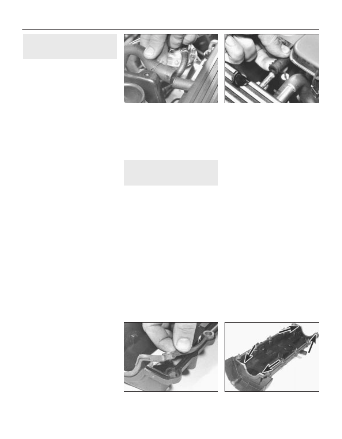
Apart from the pressed steel sump, the
plastic timing belt covers and the aluminium
alloy cylinder head cover, the engine consists
of three major castings which are the cylinder
head, the cylinder block/crankcase and the
crankshaft main bearing ladder. There is also
an oil rail underneath the main bearing ladder
and the camshaft carrier/bearing caps.
All major castings are of aluminium alloy
and are clamped together by ten long
through-bolts which perform the dual role of
cylinder head bolts and crankshaft main
bearing fasteners. Since these bolts pass
through the cylinder block/crankcase and the
main bearing ladder, the oil rail is secured also
to the main bearing ladder (by two nuts) and
the main bearing ladder is secured also to the
cylinder block/crankcase (by ten smaller bolts)
so that the cylinder head can be removed
without disturbing the rest of the engine. The
passages provided for the bolts in the major
castings are used as breather passages or as
returns for the oil to the sump.

The crankshaft runs in five main bearings.
Thrustwashers are fitted to the centre main
bearing (upper half) to control crankshaft
endfloat.
The connecting rods rotate on horizontallysplit bearing shells at their big-ends. The
pistons are attached to the connecting rods
by gudgeon pins which are an interference fit
in the connecting rod small-end eyes. The
aluminium alloy pistons are fitted with three
piston rings, comprising two compression
rings and an oil control ring.
The cylinder bores are formed by
replaceable wet liners which are located from
their top ends. Two sealing rings are fitted at
the base of each liner to prevent the escape of
coolant into the sump.
The inlet and exhaust valves are each
closed by coil springs and operate in guides
pressed into the cylinder head. The valve seat
inserts are pressed into the cylinder head and
can be renewed separately if worn.
On the K8 engine, the camshaft is driven by
a toothed timing belt and operates the eight
valves via self-adjusting hydraulic tappets,
thus eliminating the need for routine checking
and adjustment of the valve clearances. The
camshaft rotates in six bearings that are linebored direct in the cylinder head and the
(bolted-on) bearing caps. This means that the
bearing caps are not available separately from
the cylinder head and must not be
interchanged with others from another engine.
The distributor is driven from the left-hand
end of the camshaft and the mechanical fuel
pump is operated by an eccentric on the
camshaft.
Apart from the fact that it has two
camshafts, one inlet and one exhaust, each
controlling eight valves and both retained by a
single camshaft carrier, the same applies to
the K16 engine. On the K16 engine, the
distributor is driven from the left-hand end of
the inlet camshaft. The fuel pump is
electrically-operated.
On both engine types, the coolant pump is
driven by the timing belt.
Lubrication is by means of an eccentricrotor trochoidal pump mounted on the
crankshaft right-hand end. It draws oil
through a strainer located in the sump and
then forces it through an externally-mounted
full-flow cartridge-type filter into galleries in
the oil rail and cylinder block/crankcase, from
where it is distributed to the crankshaft
(main bearings) and camshaft(s). The big-end
bearings are supplied with oil via internal
drillings in the crankshaft, while the camshaft
bearings and the hydraulic tappets receive a
pressurised supply. The camshaft lobes and
valves are lubricated by splash, as are all
other engine components.
Repair operations possible with
the engine in the car
The following work can be carried out with the
engine in the vehicle:
a) Compression pressure - testing.
b) Cylinder head cover - removal and
refitting.
c) Crankshaft pulley - removal and refitting.
d) Timing belt covers - removal and refitting.
e) Timing belt - removal, refitting and
adjustment.
f) Timing belt tensioner and sprockets -
removal and refitting.
g) Camshaft oil seal(s) - renewal.
h) Camshaft(s) and hydraulic tappets -
removal, inspection and refitting.
i) Cylinder head - removal and refitting.
j) Cylinder head and pistons -
decarbonising.
k) Sump - removal and refitting.
l) Oil pump - removal, overhaul and refitting.
m) Crankshaft oil seals - renewal.
n) Engine/transmission mountings -
inspection and renewal.
o) Flywheel - removal, inspection and
refitting.
Precautions
Note that a side-effect of the above
described engine design is that the crankshaft
cannot be rotated once the cylinder head and
block through-bolts have been slackened.
During any servicing or overhaul work the
crankshaft always must be rotated to the
desired position before the bolts are
disturbed.
2 Engine oil and filter - renewal
1 Details of checking the engine oil levels and
renewing both the oil and filter are contained
in “Weekly Checks” and Chapter 1.
3 Compression test -
description and interpretation
2
1 When engine performance is down, or if
misfiring occurs which cannot be attributed to
the ignition or fuel systems, a compression
test can provide diagnostic clues as to the
engine’s condition. If the test is performed
regularly it can give warning of trouble before
any other symptoms become apparent.
2 The engine must be fully warmed up to
normal operating temperature, the battery
must be fully charged and the spark plugs
must be removed. The aid of an assistant will
be required.
3 Disable the ignition system by
disconnecting the ignition HT coil lead from
the distributor cap and earthing it on the
cylinder block. Use a jumper lead or similar
wire to make a good connection.
4 Fit a compression tester to the No 1
cylinder spark plug hole. The type of tester
which screws into the plug thread is preferred
(see illustration).
5 Have the assistant hold the throttle wide
open and crank the engine on the starter
motor. After one or two revolutions, the
compression pressure should build up to a
maximum figure and then stabilise. Record
the highest reading obtained.
6 Repeat the test on the remaining cylinders,
recording the pressure in each.
7 All cylinders should produce very similar
pressures. Any difference greater than that
specified indicates the existence of a fault.
Note that the compression should build up
quickly in a healthy engine. Low compression
on the first stroke, followed by gradually
increasing pressure on successive strokes,
indicates worn piston rings. A low
compression reading on the first stroke, which
does not build up during successive strokes,
indicates leaking valves or a blown head
gasket (a cracked head could also be the
cause). Deposits on the undersides of
the valve heads can also cause low
compression.
8 If the pressure in any cylinder is reduced to
the specified minimum or less, carry out the
following test to isolate the cause. Introduce a
teaspoonful of clean oil into that cylinder
through its spark plug hole and repeat the
test.
9 If the addition of oil temporarily improves
the compression pressure, this indicates that
bore or piston wear is responsible for the
pressure loss. No improvement suggests that
leaking or burnt valves, or a blown head
gasket, may be to blame.
10 A low reading from two adjacent cylinders
is almost certainly due to the head gasket
having blown between them and the presence
of coolant in the engine oil will confirm this.
11 If one cylinder is about 20 percent lower
than the others and the engine has a slightly
rough idle, a worn camshaft lobe could be the
cause.
12 If the compression reading is unusually
high, the combustion chambers are probably
coated with carbon deposits. If this is the
case, the cylinder head should be removed
and decarbonised.
13 On completion of the test, refit the spark
plugs and reconnect the ignition system.
Engine in-car repair procedures 2A•5
3.4 Measuring compression pressure
2A
1689 Rover 214 & 414 Updated Version 09/97
4 Top Dead Centre (TDC) for
number one piston - locating
2
General
1 The crankshaft pulley, crankshaft and
camshaft sprockets are provided by the
factory with clear marks which align only at
90° BTDC. This positions the pistons half-way
up the bores so that there is no risk of
damage as the engine is reassembled. These
marks do not indicate TDC. Use only the
ignition timing marks, as described in this
Section, to find TDC.
2 Top dead centre (TDC) is the highest point
in its travel up-and-down the cylinder bore
that each piston reaches as the crankshaft
rotates. While each piston reaches TDC both
at the top of the compression stroke and
again at the top of the exhaust stroke, for the
purpose of timing the engine, TDC refers to
the piston position (usually No 1) at the top of
its compression stroke.
3 While all engine reassembly procedures use
the factory timing marks (90° BTDC), it is
useful for several other servicing procedures
to be able to position the engine at TDC.
4 No 1 piston and cylinder is at the right-hand
(timing belt) end of the engine. Note that the
crankshaft rotates clockwise when viewed
from the right-hand side of the vehicle.
Locating TDC
5 Disconnect the battery negative lead and
remove all the spark plugs.
6 Trace No 1 spark plug (HT) lead from the
plug back to the distributor cap and use chalk
or similar to mark the distributor body or
engine casting nearest to the cap’s No 1
terminal. Undo the distributor cap retaining
screws and remove the cap.
7 Apply the handbrake and ensure that the
transmission is in neutral, then jack up the
front of the vehicle and support it on axle
stands. Remove the right-hand roadwheel.
8 From underneath the front of the vehicle,
slacken and remove the three bolts securing
the bumper flange to the body. Remove the
seven bolts securing the front undercover
panel to the body and remove the panel to
gain access to the crankshaft pulley and
ignition timing marks.
9 Using a spanner, or socket and extension
bar, applied to the crankshaft pulley bolt,
rotate the crankshaft clockwise until the notch
on the crankshaft pulley’s inboard (left-hand)
rim is aligned with the TDC mark on the timing
belt lower cover (see Chapter 1 for details of
ignition timing marks).
10 With the crankshaft in this position, Nos 1
and 4 cylinders are now at TDC, one of them
on the compression stroke. If the distributor
rotor arm is pointing at (the previously-marked)
No 1 terminal, then No 1 cylinder is correctly
positioned. If the rotor arm is pointing at No 4
terminal, rotate the crankshaft one full turn
(360°) clockwise until the arm points at the
marked terminal. No 1 cylinder will then be at
TDC on the compression stroke.
11 Once No 1 cylinder has been positioned
at TDC on the compression stroke, TDC for
any of the other cylinders can then be located
by rotating the crankshaft clockwise 180° at a
time and following the firing order.
5 Cylinder head cover -
removal and refitting
2
Removal
1 Disconnect the battery negative lead.
2 Remove the air cleaner assembly and metal
intake duct.
3 Using a suitable pair of pliers, release the
retaining clip(s) and disconnect the breather
hose(s) from the cylinder head cover (see
illustrations).
K8 engines
4 Undo the bolts securing the HT lead
mounting and air intake support brackets to
the cylinder head cover, then remove the
brackets and position the HT leads clear of
the cover.
5 Remove the two uppermost retaining
screws securing the timing belt upper righthand/outer cover to the cylinder head cover,
then slacken the remaining screws and bolts,
as necessary, until the timing belt cover can
be prised clear of the cylinder head cover
without damaging it.
6 Working progressively and in the reverse of
the tightening sequence (see illustration 5.14),
slacken and remove the cylinder head cover
retaining bolts.
7 Remove the cover, peel off the rubber seal
and check it for cuts, other damage or
distortion. Renew the seal if necessary.
K16 engines
8 Undo the two spark plug cover retaining
screws and lift off the cover. Disconnect the
HT leads from the plugs and withdraw them
from the cylinder head, along with the clip
plate and the grommet which is fitted to the
left-hand end of the cylinder head cover.
9 Working progressively and in the reverse of
the tightening sequence (see illustration 5.22),
slacken and remove the cylinder head cover
retaining bolts, noting the correct fitted position
of the air intake duct support bracket.
10 Carefully lift off the cylinder head cover,
taking care not to damage the gasket. Check
that the gasket sealing path is undamaged
and is attached to the gasket all around its
periphery. If the sealing path is undamaged,
then the gasket is re-usable and should
remain in place on the cover until reassembly,
unless its removal is necessary for other
servicing work.
Refitting
K8 engines
11 On reassembly, carefully clean the
cylinder head mating surfaces and the cover
seal’s groove and remove all traces of oil.
12 Seat the seal in its groove in the cover and
refit the bolts, pushing each through the seal,
then apply a smear of silicone-RTV sealant to
each corner of the seal (see illustrations).
2A•6 Engine in-car repair procedures
5.12b . . . then refit bolts and apply sealant
at locations arrowed - K8 engine
5.12a Ensure seal is correctly seated in
cylinder head cover groove . . .
5.3b Disconnecting breather hoses from
cylinder head cover - K16 engine
5.3a Disconnecting breather hose from
cylinder head cover - K8 engine
1689 Rover 214 & 414 Updated Version 09/97

13 Refit the cover to the cylinder head,
ensuring that the seal remains seated in its
groove. Fit all bolts, finger-tight.
14 Tighten the cylinder head cover bolts in
the sequence shown to the specified torque
wrench setting (see illustration).
15 Refit the timing belt upper righthand/outer cover to the cylinder head cover
and tighten all the disturbed screws and bolts
to the specified torque setting.
16 Refit the HT lead mounting clips and air
cleaner intake support brackets to the
cylinder head, then tighten the retaining bolts
to the specified torque. Ensure the HT leads
are correctly routed.
17 Connect the breather hose to the cylinder
head cover and secure it in position with the
retaining clip.
18 Refit the air cleaner housing and
reconnect the battery negative lead.
K16 engines
19 On reassembly, carefully clean the mating
surfaces, removing all traces of oil. If the
gasket has been removed, the oil separator
elements can be cleaned by removing them
from the cover and washing them in solvent.
Use compressed air to blow dry the elements
before refitting them to the cover.
20 If a new gasket is to be fitted, press it onto
the cover locating dowels so that if it were laid
on the camshaft carrier its stamped markings
would be legible. The TOP mark should be
nearest the inlet manifold and the EXH MAN
SIDE mark should have its arrows pointing to
the exhaust manifold (see illustrations).
21 Lower the cover onto the cylinder head,
ensuring that the gasket is not damaged or
displaced. Install the cover retaining bolts, not
forgetting to refit the air intake duct support
bracket to its original position, and tighten
them finger-tight.
22 Working in the sequence shown, tighten
the cylinder head cover retaining bolts to the
specified torque setting (see illustration).
23 Reconnect the HT leads to the spark
plugs, then locate the clip plate and grommet
in the left-hand end of the cylinder head
cover. Ensure the HT leads are correctly
routed then refit the spark plug cover and
tighten its retaining screws to the specified
torque. Tighten the air intake support bracket
screws.
24 Connect both the breather hoses to the
cylinder head cover and secure them in
position with the retaining clips.
25 Refit the air cleaner housing and
reconnect the battery negative lead.
6 Crankshaft pulley -
removal and refitting
2
Removal
1 Apply the handbrake then jack up the front
of the vehicle and support it on axle stands.
Remove the right-hand roadwheel.
2 From underneath the front of the vehicle,
slacken and remove the three bolts securing
the bumper flange to the body. Remove the
seven bolts securing the front undercover
panel to the body and remove the panel.
3 If necessary, rotate the crankshaft until the
relevant timing marks align.
4 Remove the power steering pump and/or
alternator drivebelt(s) (as applicable).
5 To prevent crankshaft rotation while the
pulley bolt is unscrewed, select top gear and
have an assistant apply the brakes firmly. If
the engine has been removed from the
vehicle, lock the flywheel using the
arrangement shown (see illustration 18.2).
6 Unscrew the pulley bolt, noting the special
washer behind it, then remove the pulley from
the crankshaft.
Refitting
7 Align the crankshaft pulley centre notch
with the locating lug on the crankshaft timing
belt sprocket then refit the washer, ensuring
that its flat surface is facing the pulley. Fit the
retaining bolt (see illustration).
8 Lock the crankshaft by the method used on
removal and tighten the pulley retaining bolt to
the specified torque setting.
9 Refit the power steering pump and/or
alternator drivebelt(s) (as applicable) and
adjust them as described in Chapter 1.
10 Refit the undercover panel and roadwheel
then lower the vehicle to the ground.
7 Timing belt covers -
removal and refitting
4
Removal
Upper right-hand (outer) cover
1 Slacken the bolt situated at the cover’s
bottom corner, immediately behind the
engine/gearbox unit right-hand mounting
bracket.
Engine in-car repair procedures 2A•7
5.20b . . . stamped markings would appear
as shown if gasket were placed on
camshaft carrier
5.20a Fit gasket to cylinder head cover
dowels (arrowed) so that . . .
5.14 Cylinder head cover bolt tightening
sequence - K8 engine
6.7 Ensure notch in crankshaft pulley
centre fits over crankshaft timing belt
sprocket locating lug (arrowed)
5.22 Cylinder head cover bolt tightening
sequence - K16 engine
2A
1689 Rover 214 & 414 Updated Version 09/97

2 Unscrew the remaining cover retaining
bolts and withdraw the cover, noting the
rubber seal fitted to the mounting bracket
edge. Note that if the cover is not slotted at
the bottom corner screw’s location, the screw
will have to be removed fully. If this is the
case, the cover can be slotted to ease future
removal and refitting (see illustrations).
Lower cover
3 Remove the crankshaft pulley.
4 Remove the cover retaining screws,
including the one which also secures the
upper cover’s bottom front corner. Remove
the cover whilst noting the rubber seal fitted to
its mounting bracket edge (see illustration).
Upper left-hand (inner) cover
5 Remove the timing belt.
6 Remove the camshaft sprocket(s) and the
timing belt tensioner.
7 Unscrew the bolt securing the cover to the
coolant pump.
8 On K16 engines, unbolt the engine/gearbox
unit right-hand mounting bracket from the
cylinder block/crankcase.
9 Remove the remaining cover retaining bolts
and withdraw the cover (see illustrations).
Refitting
Upper right-hand (outer) cover
10 Refitting is the reverse of the removal
procedure. Ensure that the seal fits correctly
between the cover and the mounting bracket
and that the cover edges mate correctly with
those of the inner cover and (K8 engines only)
cylinder head cover (see illustration).
11 Tighten the cover fasteners to the
specified torque setting.
Lower cover
12 Refitting is the reverse of the removal
procedure. Ensure that the seal fits correctly
between the cover and the mounting bracket
and tighten the cover fasteners to the
specified torque setting.
Upper left-hand (inner) cover
13 Refitting is the reverse of the removal
procedure. Tighten all disturbed fasteners to
their specified torque wrench settings.
8 Timing belt - removal,
inspection, refitting and
adjustment
4
Removal
1 Disconnect the battery negative lead.
2 To improve access to the timing belt,
remove the expansion tank mounting bolts
then free the coolant hose from any relevant
retaining clips and position the tank clear of
the engine. On models equipped with powerassisted steering, undo all the power steering
hose retaining clip bolts then slide the fluid
reservoir out of its retaining clip and position it
2A•8 Engine in-car repair procedures
7.10 Ensure timing belt upper right-hand
(outer) cover engages correctly with
cylinder head cover - K8 engine
7.9c Removing timing belt upper left-hand
(inner) cover - K16 engine
7.9b Timing belt upper left-hand (inner)
cover fasteners (arrowed) - K16 engine
7.9a Timing belt upper left-hand (inner)
cover fasteners (arrowed) - K8 engine
7.4 Removing timing belt lower cover7.2b Timing belt upper right-hand (outer)
cover fasteners (arrowed) - K16 engine,
raised for clarity
7.2a Timing belt upper right-hand (outer)
cover fasteners - K8 engine
1 Slacken screw - cover should be slotted
2 Remove fasteners
1689 Rover 214 & 414 Updated Version 09/97
If the timing belt is to be reused, use white paint or
similar to mark the direction
of rotation on the belt.

clear of the timing belt covers. Take great care
not to place any undue strain on hoses and
mop up any spilt fluid immediately.
3 Remove the timing belt upper right-hand
(outer) cover.
4 Firmly apply the handbrake then jack up the
front of the vehicle and support it on axle
stands. Remove the right-hand roadwheel
5 From underneath the front of the vehicle,
slacken and remove the three bolts securing
the bumper flange to the body. Remove the
seven bolts securing the front undercover
panel to the body and remove the panel to
gain access to the crankshaft pulley bolt.
6 Using a suitable spanner or socket on the
crankshaft pulley bolt, rotate the crankshaft in
a clockwise direction until the long whitepainted mark on the crankshaft pulley’s
outboard (right-hand) face is aligned with the
single, separate mark on the timing belt lower
cover so that the crankshaft is in the 90°
BTDC position (see Chapter 1 for details of
the pulley/cover marks) (see illustration).
7 Check that the camshaft sprocket mark(s)
align as described in paragraph 15, showing
that Nos 1 and 4 cylinders are at 90° BTDC
so that there is no risk of the valves contacting
the pistons during dismantling and
reassembly. If the camshaft sprocket mark(s)
are 180° out, rotate the crankshaft through
one complete turn (360°) to align the marks as
described (see illustration).
8 On K16 engines, use the tool described in
Section 9 to lock up the camshaft sprockets
so that they cannot move under valve spring
pressure when the timing belt is removed.
9 Remove the crankshaft sprocket and timing
belt lower cover.
10 Position a trolley jack with a wooden
spacer beneath the sump then gently jack it
up to take the weight of the engine.
11 Slacken and remove the engine/gearbox
unit right-hand mounting through-bolt and nut
and the mounting-to-bracket nuts. Remove
the mounting, along with the two rubber
washers which are fitted on each side of the
mounting. On K8 engines only, unscrew the
retaining bolts securing the bracket to cylinder
block/crankcase and remove it from the
engine unit (see illustration).
12 Slacken both the timing belt tensioner
pulley Allen screw and the tensioner
backplate clamp bolt through half a turn each,
then push the pulley assembly downwards to
remove all the tension from the timing belt.
Hold the tensioner pulley in this position and
re-tighten the backplate clamp bolt securely
(see illustration).
13 Slip the belt off the sprockets (see
illustration). Do not rotate the crankshaft until
the timing belt has been refitted.
Inspection
14 Check the timing belt carefully for any
signs of uneven wear, splitting or oil
contamination and renew it if there is the
slightest doubt about its condition. If the
engine is undergoing an overhaul and has
covered more than 48 000 miles (80 000 km)
since the original belt was fitted, renew the
belt as a matter of course, regardless of its
apparent condition. If signs of oil
contamination are found, trace the source of
the oil leak and rectify it, then wash down the
engine timing belt area and all related
components to remove all traces of oil.
Refitting
15 On reassembly, thoroughly clean the
timing belt sprockets and check that they are
aligned as follows. It is most important that
these marks are aligned exactly as this sets
valve timing. Note that in this position, Nos 1
and 4 cylinders are at 90° BTDC so that there
is no risk of the valves contacting the pistons
during dismantling and reassembly.
a) Camshaft sprocket on K8 engine - The EX
line and the mark stamped on the
sprocket rim must be at the front (looking
at the sprocket from the right-hand side
of the vehicle) and aligned exactly with
the cylinder head top surface (see
illustration).
b) Camshaft sprockets on K16 engine - Both
EXHAUST arrow marks must point to the
rear (looking at the sprockets from the
right-hand side of the vehicle) with the IN
lines and the sprocket rim marks aligned
exactly with the line on the timing belt
upper left-hand/inner cover (representing
the cylinder head top surface). See
illustration 8.7.
Engine in-car repair procedures 2A•9
8.11 Removing engine/gearbox unit righthand mounting bracket - K8 engine
8.7 Camshaft sprocket marks (A) aligned
with timing belt upper left-hand (inner)
cover mark (B) - K16 engine
8.6 Crankshaft pulley mark aligned with
timing belt lower cover mark at 90° BTDC
8.15a Camshaft sprocket marks (A)
aligned with cylinder head top surface (B) -
K8 engine
8.13 Mark direction of rotation of timing
belt before removal
8.12 Timing belt tensioner pulley bolt (A)
and tensioner backplate clamp bolt (B)
2A
1689 Rover 214 & 414 Updated Version 09/97

c) Crankshaft sprocket - The two dots must
be positioned on each side of the raised
rib on the oil pump body (see
illustration).
16 If a used belt is being refitted, ensure that
the arrow mark made on removal points in the
normal direction of rotation. Fit the timing belt
over the crankshaft and camshaft sprockets,
ensuring that the belt front run (and, on K16
engines, the top run) is taut, ie: all slack is
on the tensioner pulley side of the belt, then fit
the belt over the coolant pump sprocket and
tensioner pulley. Do not twist the belt sharply
during refitting and ensure that the belt teeth
are correctly seated centrally in the sprockets
and that the timing marks remain in alignment
(see illustration)..
17 Slacken the tensioner backplate clamp
bolt and check that the tensioner pulley
moves to tension the belt. If the tensioner
assembly is not free to move under spring
tension, rectify the fault or the timing belt will
not be correctly tensioned.
18 On K16 engines, remove the camshaft
sprocket locking tool.
19 On K8 engines, refit the engine/gearbox
unit right-hand mounting bracket, tightening
its bolts to the specified torque wrench
setting.
20 On all engines, refit the timing belt lower
cover and the crankshaft pulley.
21 Using a suitable spanner or socket, rotate
the crankshaft two full turns clockwise to
settle and tension the belt. Realign the
crankshaft pulley (90° BTDC) mark and check
that the sprocket timing mark(s) are still
correctly aligned.
22 If all is well, first tighten the tensioner
pulley backplate clamp bolt to the specified
torque, then tighten the tensioner pulley Allen
screw to the specified torque.
23 Reassemble the engine/gearbox unit
right-hand mounting, ensuring that the rubber
washers are correctly located, then tighten
the mounting nuts and bolts to their specified
torque settings. Remove the jack from
underneath the engine unit.
24 Refit the front undercover panel and
roadwheel, then lower the vehicle to the ground.
25 Refit the timing belt upper right-hand
(outer) cover.
26 Where necessary, refit the power steering
fluid reservoir to the mounting bracket and
secure the hydraulic hose clamps in position
with the retaining bolts.
27 Refit the coolant expansion tank and
tighten the mounting bolts securely. Secure
the coolant hose in position with any
necessary retaining clips and reconnect the
battery negative lead.
Adjustment
28 As the timing belt is a ‘fit-and-forget’ type,
the manufacturer states that tensioning need
only be carried out when a belt is (re)fitted. No
re-tensioning is recommended once a belt
has been fitted and therefore this operation is
not included in the manufacturer’s
maintenance schedule.
29 If the timing belt is thought to be
incorrectly tensioned, then adjust the tension
as described in paragraphs 1 to 7, 17, 21, 22
and 24 to 27 above.
30 If the timing belt has been disturbed,
adjust its tension following the same
procedure, omitting as appropriate the
irrelevant preliminary dismantling/reassembly
steps.
9 Timing belt tensioner and
sprockets - removal,
inspection and refitting
4
Note: This Section describes as individual
operations the removal and refitting of the
components concerned. If more than one
2A•10 Engine in-car repair procedures
9.2a Timing belt, sprockets and covers - K8 engine
1 Timing belt upper right-
hand (outer) cover
2 Seal
3 Bolt
4 Bolt
5 Bolt
6 Shouldered bolt
7 Timing belt lower cover
8 Seal
9 Seal
10 Bolt
11 Bolt
12 Crankshaft pulley
13 Washer
14 Crankshaft pulley bolt
15 Timing belt tensioner
pulley assembly
16 Tensioner pulley Allen
screw
17 Tensioner backplate
clamp bolt
18 Tensioner pulley spring
19 Sleeve
20 Pillar bolt
21 Timing belt
22 Crankshaft sprocket
23 Camshaft sprocket
24 Camshaft sprocket bolt
25 Washer
26 Timing belt upper left-
hand (inner) cover
27 Bolt - cover to water
pump
28 Bolt
8.16 Refitting timing belt K16 engine
8.15b Crankshaft sprocket dots (A)
aligned on each side of oil pump raised
rib (B)
1689 Rover 214 & 414 Updated Version 09/97
If both camshaft sprockets
on K16 engines are to be
removed, it is good practice
to mark them (inlet or
exhaust) so that they can be returned to
their original locations on reassembly.

component needs to be removed at the same
time, start by removing the timing belt, then
remove each component as described below
whilst ignoring the preliminary dismantling
steps.
Removal
1 Disconnect the battery negative lead.
2 To improve access to the timing belt
components (see illustrations), remove the
expansion tank mounting bolts then free the
coolant hose from any relevant retaining clips
and position the tank clear of the engine. On
models equipped with power-assisted
steering, undo all the power steering hose
retaining clip bolts then slide the fluid
reservoir out of its retaining clip and position it
clear of the timing belt covers. Take great care
not to place any undue strain on hoses and
mop up any spilt fluid immediately.
3 Remove the timing belt upper right-hand
(outer) cover.
4 Apply the handbrake then jack up the front
of the vehicle and support it on axle stands.
Remove the right-hand roadwheel.
5 From underneath the front of the vehicle,
slacken and remove the three bolts securing
the bumper flange to the body. Remove the
seven bolts securing the front undercover
panel to the body and remove the panel.
6 Using a suitable spanner or socket on the
crankshaft pulley bolt, rotate the crankshaft in
a clockwise direction until the long whitepainted mark on the crankshaft pulley’s
outboard (right-hand) face is aligned with the
single, separate mark on the timing belt lower
cover so that the crankshaft is in the 90°
BTDC position (see Chapter 1 for details of
the pulley/cover marks).
7 Check that the camshaft sprocket mark(s)
align as described in Section 8, paragraph 15
then proceed as described under the relevant
sub-heading.
Camshaft sprocket(s)
8 Slacken through half a turn each, the timing
belt tensioner pulley Allen screw and the
tensioner backplate clamp bolt. Push the
pulley assembly down to release all tension
from the timing belt, then re-tighten the
backplate clamp bolt securely.
9 Remove the belt from the camshaft
sprocket(s), taking care not to twist it too
sharply. Use fingers only to handle the belt.
Do not rotate the crankshaft until the timing
belt is refitted.
10 On K8 engines, slacken the camshaft
sprocket retaining bolt and remove it, along
with its washer. To prevent the camshaft from
rotating, use Rover service tool 18G 1521 to
retain the sprocket. If the tool is not available,
then an acceptable substitute can be
fabricated from two lengths of steel strip (one
long, the other short) and three nuts and bolts.
One nut and bolt should form the pivot of a
forked tool with the remaining two nuts and
bolts at the tips of the forks to engage with
the sprocket spokes, as shown in illustration 9.23a.
11 On K16 engines, unscrew the appropriate
camshaft sprocket retaining bolt and remove it,
along with its washer. To prevent a camshaft
from rotating, lock together both sprockets
using Rover service tool 18G 1570. This tool is
a metal sprag shaped on both sides to fit
the sprocket teeth and is inserted between the
sprockets. If the tool is not available, then an
acceptable substitute can be cut from a length
of square-section steel tube or similar to fit as
closely as possible around the sprocket
spokes (see illustrations).
12 On all engines, remove the sprocket(s)
from the camshaft end(s), noting the locating
roll pin(s) (see illustration). If a roll pin is a
Engine in-car repair procedures 2A•11
9.12 Removing camshaft sprocket (roll pin
arrowed) - K8 engine
9.11b . . . to fit sprocket spokes as closely
as possible - K16 engine
9.11a Camshaft locking tool cut from steel
section . . .
2A
1689 Rover 214 & 414 Updated Version 09/97
9.2b Timing belt, sprockets and covers - K16 engine
1 Timing belt upper right-
hand (outer) cover
2 Bolt
3 Seal
4 Bolt
5 Timing belt lower cover
6 Seal
7 Bolt
8 Bolt
9 Crankshaft pulley
10 Washer
11 Crankshaft pulley bolt
12 Timing belt
13 Camshaft sprockets
14 Bolt
15 Washer
16 Timing belt tensioner
pulley assembly
17 Tensioner pulley Allen
screw
18 Tensioner pulley spring
19 Sleeve
20 Pillar bolt
21 Tensioner backplate
clamp bolt
22 Crankshaft sprocket
23 Timing belt upper left-
hand (inner) cover
24 Bolt

loose fit in the camshaft end, remove it and
store it with the sprocket for safe-keeping.
Crankshaft sprocket
13 On K16 engines, use the tool described in
paragraph 11 to lock together the camshaft
sprockets so that they cannot move under
valve spring pressure when the timing belt is
removed.
14 Remove the crankshaft pulley and timing
belt lower cover.
15 Slacken through half a turn each the
timing belt tensioner pulley Allen screw and
the tensioner backplate clamp bolt, push the
pulley assembly down to release all the
tension from the timing belt, then re-tighten
the backplate clamp bolt securely.
16 Work the belt clear of the crankshaft
sprocket, taking care not to twist it too
sharply. Use fingers only to handle the belt.
Do not rotate the crankshaft until the timing
belt is refitted.
17 Remove the sprocket from the crankshaft.
Tensioner assembly
18 On K16 engines, use the tool described in
paragraph 11 to lock together the camshaft
sprockets so that they cannot move under
valve spring pressure when the timing belt is
removed.
19 Using a suitable pair of pliers, unhook the
tensioner spring from the pillar bolt. Unscrew
the tensioner pulley Allen screw and the
tensioner backplate clamp bolt then withdraw
the tensioner assembly from the engine unit.
Do not rotate the crankshaft until the timing
belt is re-tensioned.
Inspection
20 Clean thoroughly the camshaft/crankshaft
sprockets and renew any that show signs of
wear, damage or cracks.
21 Clean the tensioner assembly but do not
use any strong solvent which may enter the
pulley bearing. Check that the pulley rotates
freely on the backplate, with no sign of
stiffness or of free play. Renew the assembly
if there is any doubt about its condition or if
there are any obvious signs of wear or
damage. The same applies to the tensioner
spring, which should be checked with great
care as its condition is critical for the correct
tensioning of the timing belt.
Refitting
Camshaft sprocket(s)
22 If removed, refit the roll pin to the
camshaft end, ensuring that its split is facing
the centre of the camshaft, then refit the
sprocket so that the timing marks are facing
outwards (to the right). On K16 engines,
ensure that the appropriate sprocket keyway
engages with the camshaft locating pin (ie: if
refitting the inlet camshaft sprocket, engage
its IN keyway with the roll pin and so on) then
refit the sprocket retaining bolt and washer
(see illustration). Where necessary, repeat
the procedure for the second sprocket.
23 Prevent the sprocket(s) from rotating by
using the method employed on removal, then
tighten the sprocket retaining bolt(s) to the
specified torque setting. Check that the
sprocket timing marks align as described in
Section 8, paragraph 15 (see illustrations).
24 Fit the timing belt over the camshaft
sprockets, ensuring that the belt front run
(and, on K16 engines, the top run) is taut, that
is, all slack is on the tensioner pulley side of
the belt. Do not twist the belt sharply while
refitting it and ensure that the belt teeth are
correctly seated centrally in the sprockets and
that the timing marks remain in alignment.
25 Slacken the tensioner backplate clamp
bolt and check that the tensioner pulley
moves to tension the belt. If the tensioner
assembly is not free to move under spring
tension, rectify the fault or the timing belt will
not be correctly tensioned.
26 On K16 engines, remove the camshaft
sprocket locking tool.
27 Using a suitable spanner or socket, rotate
the crankshaft two full turns clockwise to
settle and tension the belt. Realign the
crankshaft pulley (90° BTDC) mark and check
that the sprocket timing mark(s) are still
correctly aligned.
28 If all is well, first tighten the tensioner
pulley backplate clamp bolt to the specified
torque, then tighten the tensioner pulley Allen
screw to the specified torque.
29 Refit the front undercover panel and
roadwheel, then lower the vehicle to the
ground.
30 Refit the timing belt upper right-hand
(outer) cover.
31 Where necessary, refit the power steering
fluid reservoir to the mounting bracket and
secure the hydraulic hose clamps in position
with the retaining bolts.
32 Refit the coolant expansion tank and
tighten the mounting bolts securely. Secure
the coolant hose in position with any
necessary retaining clips and reconnect the
battery negative lead.
Crankshaft sprocket
33 Refit the sprocket to the crankshaft so
that it locates correctly on the crankshaft’s
flattened section, noting that the sprocket
flange must be innermost so that the two
timing marks are on the outside (right-hand
side) of the sprocket. Check that the sprocket
timing marks align as described in Section 8,
paragraph 15.
34 Fit the timing belt over the crankshaft
sprocket, ensuring that the belt front run (and,
on K16 engines, the top run) is taut, that is, all
slack is on the tensioner pulley side of the
belt. Do not twist the belt sharply
while refitting it and ensure that the belt teeth
are correctly seated centrally in the
sprockets and that the timing marks remain in
alignment.
35 Slacken the tensioner backplate clamp
bolt and check that the tensioner pulley
moves to tension the belt. If the tensioner
assembly is not free to move under spring
tension, rectify the fault or the timing belt will
not be correctly tensioned.
36 On K16 engines, remove the camshaft
sprocket locking tool.
37 Refit the lower timing belt cover and the
crankshaft pulley.
38 Carry out the operations described in
paragraphs 27 to 32.
2A•12 Engine in-car repair procedures
9.23b Locking camshafts in position with
fabricated tool - K16 engine
9.23a Using fabricated tool to hold
camshaft pulley in position - K8 engine
9.22 Camshaft sprockets have two
keyways. Engage EX keyway with exhaust
camshaft roll pin and IN keyway with inlet
camshaft roll pin - K16 engine
1689 Rover 214 & 414 Updated Version 09/97

Tensioner pulley
39 Refit the tensioner pulley assembly and
tighten the pulley Allen screw and the
backplate clamp bolt lightly. Hook the
tensioner spring over the pillar bolt and check
that the tensioner is free to move under spring
tension and that the pulley bears correctly
against the timing belt (see illustration).
40 On K16 engines, remove the camshaft
sprocket locking tool.
41 Carry out the operations described above
in paragraphs 27 to 32.
10 Camshaft oil seals - renewal
4
Note: If a right-hand oil seal is to be renewed
with the timing belt still in place, then check
that the belt is free from oil contamination.
Renew the belt if signs of oil contamination
are found. Cover the belt to protect it from
contamination while work is in progress and
ensure that all traces of oil are removed from
the area before the belt is refitted.
Right-hand seal(s)
1 Remove the camshaft sprocket(s).
2 Punch or drill two small holes opposite
each other in the oil seal. Screw a self-tapping
screw into each and pull on the screws with
pliers to extract the seal.
3 Clean the seal housing and polish off any
burrs or raised edges which may have caused
the seal to fail in the first place.
4 Lubricate the lips of the new seal with clean
engine oil and drive it into position until it
seats on its locating shoulder. Use a suitable
tubular drift, such as a socket, which bears
only on the hard outer edge of the seal (see
illustration). Take care not to damage the
seal lips during fitting and note that the seal
lips should face inwards.
5 Refit the camshaft sprocket(s).
Left-hand seals - K16 engines
6 Disconnect the battery negative lead.
7 To reach the inlet camshaft seal, remove
the distributor.
8 To reach the exhaust camshaft seal,
unfasten the rubber strap securing the air
intake duct to its support bracket, disconnect
the vacuum pipe from the air temperature
control valve and unclip the pipe from the
support bracket. Undo the bracket’s retaining
bolts and remove the bracket from the
cylinder head (see illustration).
9 Remove the old seal and install the new one
as described above in paragraphs 2 to 4.
10 On the inlet camshaft, refit the distributor.
11 On the exhaust camshaft, refit the air
intake duct support bracket, tightening its
screws to the specified torque wrench setting.
Reconnect and secure the air temperature
control valve vacuum pipe and refit the rubber
strap to secure the air intake duct.
12 Connect the battery negative lead.
11 Camshafts and hydraulic
tappets - removal, inspection
and refitting
4
Note: Prior to removing the camshaft(s), obtain
Rover sealant kit LVV 10002 which also
contains a plastic scraper. Read the
instructions supplied with the kit and take care
not to allow the sealant to contact the fingers,
as it will bond the skin. If difficulty is
experienced with the removal of hardened
sealant from mating surfaces, it will be
necessary to use a foam action gasket remover.
Removal
K8 engines
1 Remove the cylinder head cover (see
illustration 11.0a overleaf).
2 Remove the distributor.
3 Remove the camshaft sprocket.
4 Carefully prise the oil feed tube away from
the camshaft bearing caps and remove it
from the head assembly. Remove the
O-rings from the oil rail and discard them.
The O-rings must be renewed whenever they
are disturbed.
5 The camshaft right and left-hand end
bearing caps are noticeably different and
cannot be confused. The intermediate bearing
caps (which are all similar) are marked by the
manufacturer with a number (1, 2, 3, or 4)
stamped in the boss next to the oil feed hole.
Before unbolting any of the caps, make
written notes to ensure that each can be
easily identified and refitted in its original
location.
6 Working in the reverse of the tightening
sequence (see illustration 11.29), slacken the
camshaft bearing cap bolts progressively, by
one turn at a time. Work only as described to
release the pressure of the valve springs on
the bearing caps gradually and evenly.
7 Withdraw the bearing caps, noting the
presence of the locating dowels on the end
caps, then remove the camshaft and withdraw
the oil seal.
8 Obtain eight small, clean plastic containers,
number them 1 to 8, and then fill them with
clean engine oil. Using a rubber sucker,
withdraw each hydraulic tappet in turn (see
illustration), and place it in its respective
container, to prevent oil loss. Do not
interchange the hydraulic tappets or the rate
of wear will be much increased and do not
allow them to lose oil or they will take a long
Engine in-car repair procedures 2A•13
10.8 Remove air intake duct support
bracket to reach exhaust camshaft left-
hand oil seal - K16 engine
10.4 Fitting a new camshaft right-hand oil
seal - K16 engine
9.39 Ensure timing belt tensioner spring is
correctly hooked onto pillar bolt
2A
1689 Rover 214 & 414 Updated Version 09/97
If faulty tappets are
diagnosed and the engine’s
service history is unknown,
it is always worth trying the
effect of renewing the engine oil and
filter (using only good quality engine oil
of the recommended viscosity and
specification) before going to the
expense of renewing any of the
tappets.
11.8 Use a valve-grinding sucker to
extract hydraulic tappets

2A•14 Engine in-car repair procedures
1689 Rover 214 & 414 Updated Version 09/97
11.0a Top end components - K8 engine
11.0b Top end components - K16 engine
1 Cylinder head cover
2 Seal
3 Engine oil filler cap
4 Seal
5 Bolt
6 HT lead retaining clip
bracket
7 Screw
8 HT lead retaining clip
9 HT lead retaining clip
10 HT lead retaining clip
bracket
11 Air intake duct support
bracket
12 Fastener insert
13 Bolt
14 Oil seal
15 Roll pin
16 Camshaft
17 Camshaft right-hand
bearing cap*
18 Dowel
19 Bolt
20 Camshaft intermediate
bearing cap*
21 Bolt
22 Camshaft left-hand
bearing cap*
23 Oil feed tube
24 O-ring
25 Cylinder head bolt
26 Cylinder head
27 Cylinder head gasket
28 Hydraulic tappet
29 Split collets
30 Spring retainer
31 Valve spring
32 Valve stem seal/ spring
lower seat
33 Valve guide
34 Inlet valve
35 Valve seat insert
36 Exhaust valve
37 Valve seat insert
38 Gasket
39 Coolant outlet elbow
40 Bolt
41 Coolant temperature
gauge sender unit
42 Spark plug
* Note: Camshaft bearing
caps shown for reference
only - not available
separately from cylinder
head
1 Spark plug cover
2 Screw
3 Retaining washer
4 Engine oil filler cap
5 Seal
6 Spark plug
7 Pillar bolt
8 HT lead grommet
9 HT lead clip plate
10 Bolt
11 Cylinder head cover
12 Gasket
13 Camshaft carrier*
14 Bolt
15 Cylinder head bolt
16 Inlet camshaft
17 Exhaust camshaft
18 Roll pin
19 Rotor arm drive
spindle
20 Oil seal
21 Hydraulic tappet
22 Split collets
23 Spring retainer
24 Valve spring
25 Valve stem seal/spring
lower seat
26 Cylinder head
27 Dowel
28 Cylinder head gasket
29 Valve guide
30 Inlet valves
31 Valve seat insert
32 Exhaust valves
33 Valve seat insert
34 Air intake duct support
bracket
35 Bolt
36 Gasket
37 Coolant outlet elbow
38 Bolt
39 Coolant temperature
gauge sender unit
* Note: Camshaft carrier
shown for reference only not available separately
from cylinder head

time to refill with oil on restarting the engine,
resulting in incorrect valve clearances.
K16 engines
9 Remove both camshaft sprockets, then
unscrew the inner cover’s upper retaining
bolts so that the cover can be pulled away
from the cylinder head just far enough for
adequate working clearance. Take care not to
distort or damage the cover or the timing belt
(see illustration).
10 Remove the cylinder head cover (see
illustration 11.0b).
11 Remove the distributor.
12 Unclip the air temperature control valve
vacuum pipe from the air intake duct support
bracket, then unbolt the bracket from the
cylinder head.
13 Working in the reverse of the tightening
sequence (see illustration 11.36), evenly and
progressively slacken the camshaft carrier
bolts by one turn at a time. Once all valve
spring pressure has been relieved, remove the
bolts.
14 Withdraw the camshaft carrier, noting the
presence of the locating dowels, then remove
the camshafts and slide off the oil seals. The
inlet camshaft can be identified by the
distributor rotor arm drive spindle (or its
location), therefore there is no need to mark
the camshafts.
15 Obtain sixteen small, clean plastic
containers, number them 1 to 16, and then fill
them with clean engine oil. Using a rubber
sucker, withdraw each hydraulic tappet in turn
(see illustration 11.8), and place it in its
respective container, to prevent oil loss. Do
not interchange the hydraulic tappets or the
rate of wear will be much increased and do
not allow them to lose oil or they will take a
long time to refill with oil on restarting the
engine, resulting in incorrect valve clearances.
Inspection
16 Check each hydraulic tappet for signs of
obvious wear (scoring, pitting, etc) and for
ovality. Renew if necessary.
17 If the engine’s valve clearances have
sounded noisy, particularly if the noise
persists after initial start-up from cold, then
there is reason to suspect a faulty hydraulic
tappet. Only a good mechanic experienced in
these engines can tell whether the noise level
is typical, or if renewal is warranted of one or
more of the tappets.
18 If any tappet’s operation is faulty, then it
must be renewed.
19 Carefully remove all traces of old sealant
from the mating surfaces of the bearing caps
or camshaft carrier and cylinder head by using
a plastic scraper. Examine the camshaft
bearing journals and the cylinder head bearing
surfaces for signs of obvious wear or pitting. If
any such signs are evident, renew the
component concerned.
20 To check the bearing journal running
clearance, remove the hydraulic tappets,
carefully clean the bearing surfaces and refit
the camshaft(s) and carrier/bearing caps with a
strand of Plastigauge across each journal.
Tighten the carrier/bearing cap bolts to the
specified torque wrench setting whilst taking
great care not to rotate the camshaft(s), then
remove the carrier/bearing caps and use the
scale provided with the Plastigauge kit to
measure the width of each compressed strand.
21 If the running clearance of any bearing is
found to be worn to the specified service limit
or beyond, fit a new camshaft and repeat the
check. If the clearance is still excessive, then
the cylinder head must be renewed.
22 To check camshaft endfloat, remove the
hydraulic tappets, carefully clean the bearing
surfaces and refit the camshaft(s) and
carrier/bearing caps. Tighten to the specified
torque wrench setting the carrier/bearing cap
bolts, then measure the endfloat using a Dial
Test Indicator (DTI) or dial gauge mounted on
the cylinder head so that its tip bears on the
camshaft right-hand end.
23 Tap the camshaft fully towards the gauge,
zero the gauge, then tap the camshaft fully
away from the gauge and note the gauge
reading. If the endfloat measured is found to
be worn to the specified service limit or
beyond, fit a new camshaft and repeat the
check. If the clearance is still excessive, then
the cylinder head must be renewed.
24 The camshaft itself should show no signs of
marks, pitting or scoring on the lobe surfaces. If
such marks are evident, renew the camshaft.
25 If a camshaft is renewed, extract the roll
pin from the old one and fit the pin to the new
camshaft with its split towards the camshaft’s
centre.
Refitting
K8 engines
26 Liberally oil the cylinder head hydraulic
tappet bores and the tappets (see
illustration). Note that if new tappets are
being fitted, they must be charged with clean
engine oil before installation. Carefully refit the
tappets to the cylinder head, ensuring that
each tappet is refitted to its original bore and is
the correct way up. Some care will be required
to enter the tappets squarely into their bores.
27 Liberally oil the camshaft bearings and
lobes then refit the camshaft. Position the
shaft so that its No 1 cylinder lobes are
pointing away from their valves and the roll
pin in the camshaft’s right-hand end is in the
4 o’clock position when viewed from the righthand end of the engine (see illustration).
28 Ensure that the locating dowels are
pressed firmly into their recesses. Check that
the mating surfaces are completely clean,
unmarked and free from oil, then apply a thin
bead of special Rover sealant to the mating
surfaces of the front and rear bearing caps as
shown (see illustration 11.29). Carefully
follow the instructions supplied with the
sealant kit. Refit the bearing caps, using the
notes made on removal, to ensure that each is
installed correctly and in its original location
(see illustration).
Engine in-car repair procedures 2A•15
11.28 Apply sealant (arrowed) and fit
camshaft bearing caps - K8 engine
11.27 Camshaft roll pin location at TDC
position (for refitting camshaft bearing
caps) - K8 engine
11.26 Lubricate hydraulic tappets
thoroughly and refit correct way up -
K8 engine
2A
1689 Rover 214 & 414 Updated Version 09/97
11.9 Secure partly-removed timing belt
upper left-hand (inner) cover clear of
cylinder head - K16 engine

29 Working in the sequence shown (see
illustration), progressively tighten the
camshaft bearing cap bolts by one turn at a
time until the caps touch the cylinder head
evenly. Now go round again, working in the
same sequence, and tighten all the bolts to
the specified torque setting. Work only as
described to impose the pressure of the valve
springs gradually and evenly on the
bearing caps. Wipe off all surplus sealant so
that none is left to find its way into any
oilways.
30 Squirt clean engine oil into each camshaft
bearing cap oil hole, then fit new O-rings to
each of the oil feed tube stubs (see
illustration). Refit the oil feed tube to the
cylinder head and press it firmly into position
in the camshaft bearing caps.
31 Fit a new camshaft oil seal (see
illustration), then refit the cylinder head cover
and camshaft sprocket.
32 Refit the distributor.
K16 engines
33 Liberally oil the cylinder head hydraulic
tappet bores and the tappets. Note that if new
tappets are being fitted, they must be charged
with clean engine oil before installation.
Carefully refit the tappets to the cylinder head,
ensuring that each tappet is refitted to its
original bore and is the correct way up. Some
care will be required to enter the tappets
squarely into their bores.
34 Liberally oil the camshaft bearings and
lobes and refit them to the cylinder head.
Position each shaft so that its No 1 cylinder
lobes are pointing away from their valves.
With the shafts in this position, the roll pin in
the inlet camshaft’s right-hand end will be in
the 4 o’clock position when viewed from the
right-hand end of the engine, while that of the
exhaust camshaft will be in the 8 o’clock
position (see illustration).
35 Ensure that the locating dowels are
pressed firmly into their recesses, check that
the mating surfaces are completely clean,
unmarked and free from oil, then apply a thin
bead of special Rover sealant to the mating
surfaces of the camshaft carrier as shown
(see illustration). Carefully follow the
instructions supplied with the sealant kit. Refit
the carrier.
36 Working in the sequence shown (see
illustration), progressively tighten the
camshaft carrier bolts by one turn at a time
until the carrier touches the cylinder head
evenly. Now go round again, working in the
same sequence, tightening all bolts to the
specified torque setting. Work only as
described to impose the pressure of the valve
springs gradually and evenly on the carrier.
Wipe off all surplus sealant so that none is left
to find its way into any oilways.
37 Fit new camshaft oil seals, then refit the
cylinder head cover, inner timing cover
retaining bolts and camshaft sprockets.
38 Refit the distributor.
39 Refit the air intake duct support bracket,
tightening its screws to their specified torque
wrench setting, then reconnect and secure
the air temperature control valve vacuum pipe
and refit the rubber strap to secure the air
intake duct.
2A•16 Engine in-car repair procedures
11.36 Camshaft carrier bolt tightening
sequence - K16 engine
11.35 Apply thin bead of sealant to
camshaft carrier mating surfaces along
paths shown by heavy black lines -
K16 engine
11.31 Fitting a new camshaft right-hand
oil seal - K8 engine
11.34 Camshaft roll pin locations at TDC
position for refitting camshaft carrier
(arrowed) - K16 engine
11.30b Renew O-rings (arrowed) before
refitting oil feed tube - K8 engine
11.30a Fill oil holes with clean engine oil K8 engine
11.29 Camshaft bearing cap bolt
tightening sequence - K8 engine
Note: Apply thin bead of sealant to end
bearing cap mating surfaces along paths
shown by heavy black lines
1689 Rover 214 & 414 Updated Version 09/97
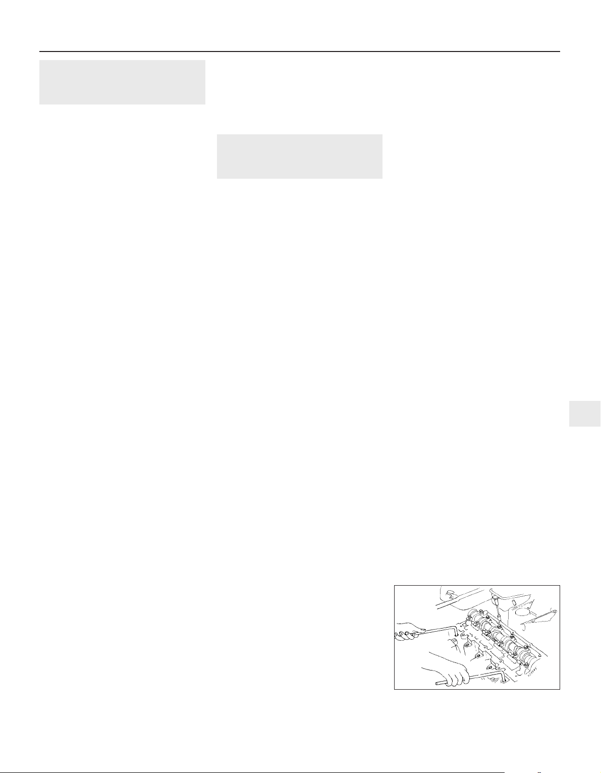
12 Valve clearances -
general information
1 It is necessary for a clearance to exist
between the tip of each valve stem and the
valve operating mechanism. This allows for
expansion of the various engine components
as the engine reaches normal operating
temperature.
2 On most older engine designs, this meant
that the valve clearances (also known as
‘tappet’ clearances) had to be checked and
adjusted regularly. If the clearances were too
slack, the engine would be very noisy, its
power output would suffer and its fuel
consumption would increase. Conversely, if
the clearances were too tight, the engine’s
power output would be reduced and the
valves and their seats could be severely
damaged.
3 The engines covered in this Manual employ
hydraulic tappets which use engine oil
pressure to automatically take up the
clearance between each camshaft lobe and
its respective valve stem. This means that
there is no need for regular checking and
inspection of the valve clearances, but it is
essential that only good quality oil of the
recommended viscosity and specification is
used in the engine and that this oil is
scrupulously changed at the recommended
intervals. If this advice is not followed, the
oilways and tappets may become clogged
with particles of dirt or deposits of burnt
engine oil, so that the system cannot work
properly. Ultimately, one or more of the
tappets may fail and expensive repairs may
be required.
4 On starting the engine from cold, there will
be a slight delay while full oil pressure builds
up in all parts of the engine, especially in the
tappets. The valve clearances, therefore, may
well rattle for about 10 seconds or so and
then quieten. This is a normal state of affairs
and is nothing to worry about, provided that
all tappets quieten quickly and stay quiet.
5 After the vehicle has been standing for
several days, the valve clearances may rattle
for longer than usual as nearly all the oil will
have drained away from the engine’s top end
components and bearing surfaces. While this
is only to be expected, care must be taken not
to damage the engine by running it at high
speed until all the tappets are refilled with oil
and operating normally. With the vehicle
stationary, hold the engine at no more than a
fast idle speed (maximum 2000 to 2500 rpm)
for 10 to 15 minutes or until the noise ceases.
Do not run the engine at more than 3000 rpm
until all tappets are fully recharged with oil and
all noise has ceased.
6 If the valve clearances are thought to be
noisy, or if a light rattle persists from the
engine’s top end after it has reached normal
operating temperature, take the vehicle to a
Rover dealer for expert advice. Depending on
the mileage covered and the usage to which
each vehicle has been put, some vehicles may
be noisier than others. Only a good mechanic
experienced in these engines can tell if the
noise level is typical for the vehicle’s mileage
or if a genuine fault exists. If any tappet’s
operation is faulty, then it must be renewed.
13 Cylinder head -
removal and refitting
4
Note: Due to engine design, it will become
very difficult, almost impossible, to turn the
crankshaft once the cylinder head bolts have
been slackened. The manufacturer states that
the crankshaft will be ‘tight’ and should not be
rotated more than absolutely necessary once
the head has been removed. If the crankshaft
cannot be rotated, then it must be removed
for overhaul work to proceed. With this in
mind, the crankshaft always must be rotated
to the desired position before the bolts are
disturbed.
Removal
1 Disconnect the battery negative lead.
2 Drain the cooling system.
3 Remove the camshaft sprocket(s).
4 Unscrew the bolts securing the timing belt
upper left-hand (inner) cover to the cylinder
head, so that the cover can be pulled away
from the cylinder head just far enough for
adequate working clearance. Take care not to
distort or damage the cover or the timing belt.
5 Remove the cylinder head cover.
6 Disconnect the exhaust system front pipe
from the manifold and, where fitted,
disconnect or release the lambda sensor
wiring so that it is not strained by the weight
of the exhaust.
7 Note that the following text assumes that
the cylinder head will be removed with both
inlet and exhaust manifolds attached. This is
easier but makes it a bulky and heavy
assembly to handle. If it is wished first to
remove the manifolds, proceed as described
in the relevant Sections of Chapter 4.
8 On carburettor engines, disconnect the
following from the carburettor and inlet
manifold as described in the relevant Sections
of Chapter 4A:
a) Fuel pump feed hose - plug both
openings to prevent loss of fuel and entry
of dirt into system.
b) Carburettor idle bypass solenoid wires.
c) Accelerator cable.
d) Choke cable.
e) Vacuum servo unit vacuum hose.
f) Inlet manifold PTC heater wire.
g) Inlet manifold heater temperature switch
wiring.
9 On fuel-injected engines, refer to the
relevant Sections of Chapter 4B or C, and
disconnect or remove all throttle body/fuel rail
components appertaining to cylinder head
removal, noting the following:
a) The fuel system must be depressurised
before any component is disconnected.
b) Plug the open ends of all disconnected
pipes to prevent loss of fuel and entry of
dirt into system.
c) Discard all sealing washers and O-rings,
these must be renewed.
10 Working as described in Chapter 3,
disconnect the connector plug from the
coolant temperature sensor screwed into the
coolant outlet elbow, then disconnect the
coolant hoses from the (three) inlet manifold
unions and from the coolant outlet elbow.
11 Unclip the engine wiring harness from the
inlet manifold or its support stays. Slacken the
bolts securing the stays to the manifold, then
unbolt the support stays and the carburettor
metal overflow pipes from the cylinder
block/crankcase.
12 Remove the distributor cap, complete
with the spark plug HT leads. Remove the
spark plugs.
13 On K16 engines equipped with air
conditioning, undo the nuts and bolts
securing the heat shields to the rear of the
alternator and air conditioning compressor
and remove both heat shields. Slacken the
two lower alternator mounting bolts then
remove the upper mounting bolt and pivot the
alternator away from the cylinder head.
14 Working in the reverse of the tightening
sequence (see illustrations 13.29a or
13.29b), progressively slacken the ten
cylinder head bolts by one turn at a time. A
female Torx-type socket (No 12 size) will be
required. Remove each bolt in turn and store
it in its correct fitted order by pushing it
through a clearly-marked cardboard template.
15 The joint between the cylinder head and
gasket and the cylinder block/crankcase must
now be broken without disturbing the wet
liners. Although these liners are better located
and sealed than some wet liner engines, there
is still a risk of coolant and foreign matter
leaking into the sump if the cylinder head is
lifted carelessly. If care is not taken and the
liners are moved, there is also a possibility of
the bottom seals being disturbed, causing
leakage after refitting the head.
16 To break the joint, obtain two L-shaped
metal bars which fit into the cylinder head bolt
holes and gently rock the cylinder head free
towards the front of the vehicle (see
illustration). Do not try to swivel the head on
Engine in-car repair procedures 2A•17
13.16 Using two cranked bars to break
cylinder head joint
2A
1689 Rover 214 & 414 Updated Version 09/97

the cylinder block/crankcase as it is located
by dowels as well as by the tops of the liners.
17 With the joint broken, lift the cylinder head
away, using assistance if possible as it is a
heavy assembly, especially if complete with
the manifolds. Remove the gasket, noting the
two locating dowels, and discard it.
18 Further to the warnings given in the note
at the beginning of this Section, do not
attempt to rotate the crankshaft with the
cylinder head removed, otherwise the wet
liners may be displaced. Operations that
would normally require the rotation of the
crankshaft (eg: cleaning the piston crowns)
must be carried out with great care to ensure
that no particles of dirt or foreign matter are
left behind. If cylinder liner clamps are to be
used, they must be clamped in place using
spacers fitted under the heads of the cylinder
head bolts.
19 If the cylinder head is to be dismantled,
remove the camshaft(s) then refer to the
relevant Sections of Part B of this Chapter.
Refitting
20 Check the condition of the cylinder head
bolts, particularly their threads. Keeping all
bolts in their correct fitted order, wash them
and wipe dry. Check each bolt for any sign of
visible wear or damage, renewing as
necessary. Lightly oil the threads of each bolt,
carefully enter it into its original hole and
screw it in, by hand only until finger-tight.
Measure the distance from the cylinder
block/crankcase gasket surface to under the
bolt’s head (see illustration).
21 If the distance measured is under 97 mm,
the bolt may be re-used. If the distance
measured is more than 97 mm, the bolt must
be renewed. Considering the task these bolts
perform and the pressures they must
withstand, owners should consider renewing
all the bolts as a matched set if more than one
of the originals fail inspection or are close to
the limit set.
22 The mating faces of the cylinder head and
cylinder block/crankcase must be perfectly
clean before refitting the head. Use a hard
plastic or wood scraper to remove all traces of
gasket and carbon.
23 Check the mating surfaces of the cylinder
block/crankcase and the cylinder head for
nicks, deep scratches and other damage. If
slight, they may be removed carefully with a
file, but if excessive, machining may be the
only alternative to renewal.
24 If warpage of the cylinder head gasket
surface is suspected, use a straight-edge to
check it for distortion. Refer to Part B of this
Chapter if necessary.
25 Wipe clean the mating surfaces of the
cylinder head and cylinder block/crankcase.
Check that the two locating dowels are in
position at each end of the cylinder
block/crankcase surface.
26 Position a new gasket on the cylinder
block/crankcase surface so that its TOP mark
is uppermost and the FRONT arrow points to
the timing belt end (see illustrations).
27 Refit the cylinder head, locating it on the
dowels (see illustration).
28 Keeping all the cylinder head bolts in their
correct fitted order, wash them and wipe dry.
Lightly oil under the head and on the threads
of each bolt, carefully enter it into its original
hole and screw it in, by hand only, until fingertight.
29 Working progressively and in the
sequence shown (see illustrations), use first
a torque wrench, then an ordinary socket
extension bar to tighten the cylinder head
bolts through the specified stages. To tighten
the bolts through the specified angles, simply
use a felt-tip pen or similar to mark the
position on the cylinder head of each bolt
head’s radial mark. The second stage then
2A•18 Engine in-car repair procedures
13.29c Alignment of bolt head radial
marks with cylinder head to establish
tightening angles (arrowed)
13.29b Cylinder head bolt tightening
sequence - K16 engine
13.29a Cylinder head bolt tightening
sequence - K8 engine
13.27 Refitting the cylinder head
13.26b . . . so that TOP mark is upwards
and FRONT arrow points to timing belt end
13.26a Fit new cylinder head gasket on
two locating dowels (arrowed) . . .
13.20 Checking condition of cylinder head
bolt threads - cylinder head removed
1689 Rover 214 & 414 Updated Version 09/97

tightens each bolt through half a turn so that
the marks face away from each other and the
third stage tightens them through another
half-turn so that all the bolt-head marks will
then align again with their cylinder head
counterparts. If any bolt is overtightened past
its mark, slacken it through 90°, then retighten until the marks align (see illustration).
30 Refit and tighten the inlet manifold
support stay bolts, then secure the engine
wiring harness using the clips provided.
31 On K16 engines equipped with air
conditioning, refit the alternator mounting
bolts and tighten them to the specified torque
setting. Refit the compressor and alternator
heatshields, tightening their retaining bolts
and nuts securely.
32 Connect all disturbed coolant hoses,
securing them in position with their retaining
clips. Reconnect the coolant temperature
sensor wiring.
33 Working as described in Chapter 4,
connect or refit all disturbed wiring, hoses and
control cable(s) to the inlet manifold and fuel
system components, then adjust the choke
and or accelerator cable(s).
34 Reconnect the exhaust system front pipe
to the manifold and (if applicable) reconnect
the lambda sensor wiring.
35 Refit the cylinder head cover, inner timing
cover retaining bolts and camshaft
sprocket(s).
36 Refit the spark plugs and distributor cap
then reconnect the battery negative lead.
37 Refill the cooling system.
14 Sump -
removal and refitting
2
Note: It is essential that new bolts of the
Patchlok type are used when refitting the
sump.
Removal
1 Disconnect the battery negative lead.
2 Drain the engine oil then clean and refit the
engine oil drain plug, tightening it to the
specified torque wrench setting. If the engine
is nearing its service interval when the oil and
filter are due for renewal, it is recommended
that the filter is also removed and a new one
fitted. After reassembly, the engine can then
be replenished with fresh engine oil.
3 Apply the handbrake, then jack up the front
of the vehicle and support it on axle stands.
Remove the right-hand roadwheel.
4 From underneath the front of the vehicle,
slacken and remove the three bolts securing
the bumper flange to the body. Remove the
seven bolts securing the front undercover
panel to the body and remove the panel.
5 Working as described in Chapter 4,
disconnect the exhaust system front pipe
from the manifold and, where fitted,
disconnect or release the lambda sensor
wiring so that it is not strained by the weight
of the exhaust.
6 Unscrew the three retaining bolts and
remove the flywheel lower cover plate (see
illustration).
7 Slacken and remove the bolts securing the
anti-beaming bracket to the engine and
transmission and remove the bracket.
8 Progressively slacken the sump retaining
bolts then remove them along with the antibeaming bracket support. Make a note of the
correct fitted position of the support and of
the longer bolts at positions 4, 8 and 12 (see
illustration 14.14) to ensure correct refitment
on reassembly.
9 Break the joint by striking the sump with the
palm of the hand, then lower the sump and
withdraw it (see illustration).
10 While the sump is removed, take the
opportunity to unbolt the oil pump pickup/strainer pipe and clean it using a suitable
solvent. Inspect the strainer mesh for signs of
clogging or splitting and renew if necessary.
Refitting
11 Clean all traces of gasket from the mating
surfaces of the cylinder block/crankcase and
sump, then use a clean rag to wipe out
the sump and the engine’s interior. If the oil
pump pick-up/strainer pipe was removed, fit a
new sealing O-ring to its end and refit the
pipe, tightening its retaining bolts to the
specified torque setting.
12 If the sump gasket is damaged or shows
signs of deterioration, then it must be
renewed. Fit the gasket to the sump mating
surface so that its 7 locating pegs fit into the
sump holes (see illustration).
13 Offer up the sump to the cylinder
block/crankcase then fit the new sump
retaining bolts, not forgetting the antibeaming bracket support. Tighten the bolts
finger-tight only.
14 Working in the sequence shown (see
illustration), tighten the sump bolts to the
specified torque setting.
15 Refit the anti-beaming bracket and tighten
the mounting bolts to the specified torque
setting.
16 Install the flywheel lower cover plate and
tighten the retaining bolts to the specified
torque wrench setting.
17 Reconnect the exhaust system front pipe
to the manifold and, where necessary,
reconnect the lambda sensor wiring.
18 Refit the undercover panel and wheel,
then lower the vehicle to the ground and
reconnect the battery negative lead.
19 Replenish the engine oil.
15 Oil pump -
removal and refitting
4
Note: The oil pressure relief valve can be
dismantled without removing the oil pump
from the vehicle. See Section 16 for details.
Removal
1 Remove the crankshaft sprocket and
secure the timing belt clear of the working
Engine in-car repair procedures 2A•19
14.9 Removing the sump14.6 Remove flywheel lower cover plate to
reach sump bolts
14.14 Sump bolt tightening sequence14.12 Sump gasket pegs must engage
with sump mating surface holes
2A
1689 Rover 214 & 414 Updated Version 09/97
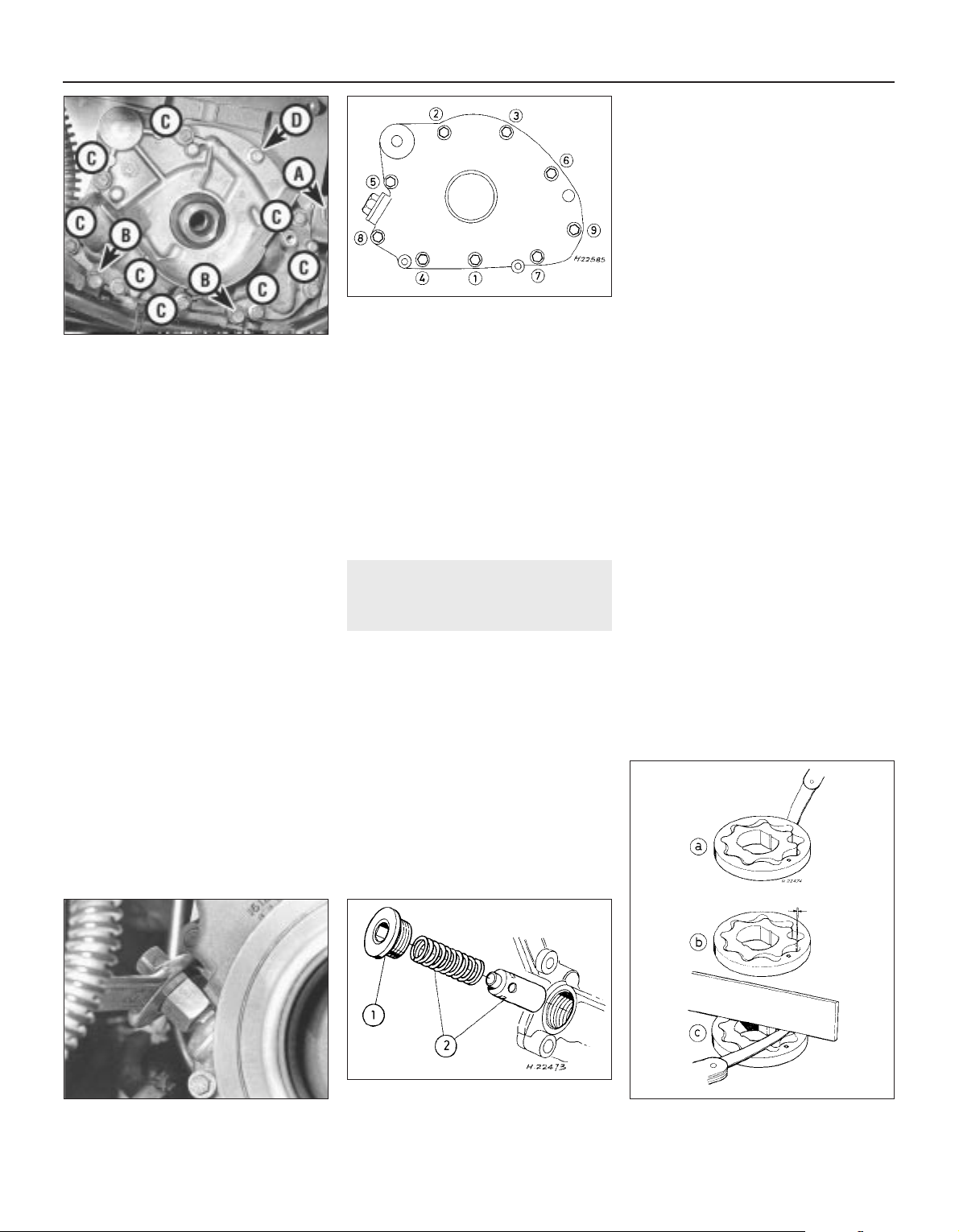
area so that it cannot be contaminated with
oil.
2 Drain the engine oil, then clean and refit the
engine oil drain plug, tightening it to the
specified torque wrench setting. If the engine
is nearing its service interval when the oil and
filter are due for renewal, it is recommended
that the filter is also removed and a new one
fitted. After reassembly, the engine can then
be replenished with fresh engine oil.
3 Where necessary, unscrew the alternator
adjuster link retaining nut and unbolt the
engine wiring harness guide retaining screws,
then move the link and guide clear of the oil
pump.
4 Unscrew the oil pump retaining bolts,
noting the fitted position of the special bolt,
and withdraw the oil pump (see illustration).
Recover the pump gasket and discard it, then
carefully lever the crankshaft right-hand oil
seal out of the oil pump. The oil seal should be
renewed whenever it is disturbed.
Refitting
5 Thoroughly clean the mating faces of the oil
pump and cylinder block/crankcase. Use
grease to stick a new gasket in place.
6 Prime the pump before installation by
injecting clean engine oil into it and turning it
by hand.
7 Offer up the pump, ensuring that its inner
gear engages fully on the crankshaft flats,
then push the pump fully into position.
8 Refit the pump retaining bolts, ensuring that
the special bolt is refitted to its original
position. Tighten the retaining bolts to the
specified torque setting in the order shown
(see illustration).
9 If removed, refit the alternator adjuster link
and the engine wiring harness guide, then
tighten securely the retaining nut and screws.
10 Fit a new crankshaft right-hand oil seal.
11 Remove all traces of surplus oil then refit
the crankshaft sprocket.
12 Replenish the engine oil.
16 Oil pump - dismantling,
inspection and reassembly
4
Note: If oil pump wear is suspected, check the
cost and availability of new parts (only
available in the form of repair kit LQX 10001)
against the cost of a new pump. Examine the
pump as described in this Section and then
decide whether renewal or repair is the best
course of action.
Dismantling
1 Remove the oil pump.
2 Unscrew the Torx screws (size T25) and
remove the pump cover plate. Discard the
sealing ring.
3 Note the identification marks on the outer
rotor then remove both the rotors from the
body.
4 The oil pressure relief valve can be
dismantled, if required, without disturbing the
pump. If this is to be done with the pump in
position and the engine still installed in the
vehicle, it will first be necessary to jack up the
front of the vehicle and remove the right-hand
roadwheel to gain access to the valve (see
illustration).
5 To dismantle the valve, unscrew the
threaded plug and recover the valve spring
and plunger (see illustration). Discard the
plug sealing washer.
Inspection
6 Inspect the rotors for obvious signs of wear
or damage and renew if necessary. If the
pump body or cover plate is scored or
damaged, then the complete oil pump
assembly must be renewed.
7 Using feeler gauge blades of the
appropriate thickness, measure the clearance
between the outer rotor and the pump body,
then between the tips of the inner and outer
rotor lobes (a and b respectively) (see
illustration).
8 Using feeler gauge blades and a straight-
edge placed across the top of the pump body
and the rotors, measure the rotor endfloat (c).
9 If any measurement is outside the specified
limits, the complete pump assembly must be
renewed.
10 If the pressure relief valve plunger is
scored, or if it does not slide freely in the
pump body bore, then it must be renewed,
using all the components from the repair kit.
11 To complete a thorough inspection of the
oil pump components, the sump should be
removed and the oil pump pick-up/strainer
pipe removed and cleaned.
Reassembly
12 Lubricate the pump rotors with clean
engine oil and refit them to the pump body,
2A•20 Engine in-car repair procedures
16.7 Checking oil pump rotors for wear see text for details
16.5 Oil pressure relief valve assembly
1 Threaded plug
2 Valve spring and plunger
16.4 Unscrewing oil pressure relief valve
threaded plug
15.8 Oil pump bolt tightening sequence
15.4 Alternator adjuster link nut (A) wiring
guide screws (B) oil pump bolts (C) and
special oil pump bolt (D)
1689 Rover 214 & 414 Updated Version 09/97

ensuring that the outer rotor’s identification
mark faces outwards (see illustration).
13 Fit a new sealing ring to the pump body
and refit the cover plate. Apply thread-locking
compound to the threads of the cover plate
Torx screws and tighten them securely.
14 Check that the pump rotates freely, then
prime it by injecting oil into its passages and
rotating it. If a long time elapses before the
pump is refitted to the engine, prime it again
before installation.
15 Refit the oil pressure relief valve plunger,
ensuring that it is the correct way up, then
install the spring. Fit a new sealing washer to
the threaded plug and tighten the plug
securely.
17 Crankshaft oil seals -
renewal
4
Right-hand seal
1 Remove the crankshaft sprocket and
secure the timing belt clear of the working
area so that it cannot be contaminated with
oil.
2 Punch or drill two small holes opposite
each other in the seal. Screw a self-tapping
screw into each and pull on the screws with
pliers to extract the seal.
3 Clean the seal housing and polish off any
burrs or raised edges which may have caused
the seal to fail in the first place.
4 Lubricate the lips of the new seal with clean
engine oil and drive it into position until it
seats on its locating shoulder. Use a suitable
tubular drift, such as a socket, which bears
only on the hard outer edge of the seal. Take
care not to damage the seal lips during fitting.
Use either grease or a thin layer of insulating
tape to protect the seal lips from the edges of
the crankshaft flats but be careful to remove
all traces of tape and to lubricate the seal lips
if the second method is used. Note that the
seal lips should face inwards.
5 Wash off any traces of oil, then refit the
crankshaft sprocket.
Left-hand seal
6 Remove the flywheel.
7 Taking care not to mark either the
crankshaft or any part of the cylinder
block/crankcase, lever the seal evenly out of
its housing.
8 Clean the seal housing and polish off any
burrs or raised edges which may have caused
the seal to fail in the first place.
9 Lubricate with grease the lips of the new
seal and the crankshaft shoulder, then offer
up the seal to the cylinder block/crankcase.
10 Ease the sealing lip of the seal over the
crankshaft shoulder by hand only, then press
the seal evenly into its housing until its outer
flange seats evenly on the housing lip. If
necessary, a soft-faced mallet can be used to
tap the seal gently into place.
11 Wash off any traces of oil, then refit the
flywheel.
18 Flywheel - removal,
inspection and refitting
5
Removal
1 Remove the gearbox and the clutch
assembly.
2 Prevent the flywheel from turning by locking
the ring gear teeth (see illustration) or by
bolting a strap between the flywheel and the
cylinder block/crankcase.
3 Slacken and remove the flywheel retaining
bolts and discard them The bolts must be
renewed whenever they are disturbed.
4 Remove the flywheel. Do not drop it, as it is
very heavy.
Inspection
5 If the flywheel’s clutch mating surface is
deeply scored, cracked or otherwise
damaged, then the flywheel must be renewed,
unless it is possible to have it surface ground.
Seek the advice of a Rover dealer or engine
reconditioning specialist.
6 If the ring gear is badly worn or has missing
teeth, then it must be renewed. This job is
best left to a Rover dealer or engine
reconditioning specialist. The temperature to
which the new ring gear must be heated for
installation (350°C - shown by an even light
blue colour) is critical and, if not done
accurately, the hardness of the teeth will be
destroyed.
7 Examine the reluctor ring (fitted to the rear
of the flywheel) for signs of damage and
check that it is securely fastened by the two
retaining screws. If the reluctor ring is
damaged, then it must be renewed.
Refitting
8 Clean the mating surfaces of the flywheel
and crankshaft. Clean any remaining adhesive
from the threads of the crankshaft threaded
holes by making two saw cuts at opposite
points along the (carefully-cleaned) threads of
one of the original flywheel bolts and screwing
it into each hole in turn. Do not use a tap to
clean the threads in this way.
9 Position the flywheel over the crankshaft’s
locating dowel, press it into place and fit six
new bolts.
10 Lock the flywheel using the method
employed on dismantling, then tighten the
retaining bolts to the specified torque wrench
setting.
11 Refit the clutch, then remove the locking
tool and refit the gearbox.
19 Engine/gearbox mountings -
inspection and renewal
2
Inspection
1 If improved access is required, raise the
front of the vehicle and support it securely on
axle stands.
2 Check the mounting rubber to see if it is
cracked, hardened or separated from the
metal at any point. Renew the mounting if any
such damage or deterioration is evident.
3 Check that all mounting fasteners are
securely tightened. Use a torque wrench to
check, if possible.
4 Using a large screwdriver or a pry bar,
check for wear in the mounting by carefully
levering against it to check for free play.
Where this is not possible, enlist the aid of an
assistant to move the engine/gearbox unit
back and forth or from side to side while
you watch the mounting. While some free play
is to be expected even from new
components, excessive wear should be
obvious. If excessive free play is found, check
first that the fasteners are correctly secured,
then renew any worn components as
described below.
Renewal
Right-hand mounting
5 Disconnect the battery negative lead.
6 To improve access to the mounting,
remove the expansion tank mounting bolts
then free the coolant hose from any relevant
retaining clips and position the tank clear of
the engine. On models equipped with powerassisted steering, undo all the power steering
hose retaining clamp bolts then slide the fluid
Engine in-car repair procedures 2A•21
18.2 Using fabricated tool to lock flywheel
in position
16.12 Oil pump outer rotor outside face
identifying mark (arrowed)
2A
1689 Rover 214 & 414 Updated Version 09/97

reservoir out of its retaining clip and position it
clear of the timing belt covers. Take great care
not to place any undue strain on hoses and
mop up any spilt fluid immediately.
7 Support the weight of the engine/gearbox
unit by using a trolley jack, with a wooden
spacer to prevent damage to the sump.
Unscrew the mounting through-bolt and nut
and the mounting to bracket nuts. Remove
the mounting, noting the two rubber washers
(see illustrations).
8 Where necessary, unscrew the retaining
bolts and remove the bracket from the
cylinder block/crankcase.
9 Check carefully for signs of wear or damage
on all components and renew them where
necessary.
10 On reassembly, refit the bracket to the
cylinder block/crankcase and tighten the
retaining bolts to the specified torque setting.
11 Locate the rubber washers on the
mounting, one on each side of its centre boss,
then refit the mounting to the bracket and
tighten the retaining nuts, finger-tight only.
12 Using the trolley jack to position the
engine unit at the correct height, refit from
rear to front the mounting-to-body throughbolt, ensuring that the rubber washers are
correctly seated, then refit the nut (see
illustration).
13 Tighten the mounting to bracket nuts and
the through-bolt to the specified torque
wrench settings, then lower and remove the
jack.
14 Where necessary, refit the power steering
fluid reservoir to its mounting bracket and
secure the hydraulic hose clamps in position
with the retaining bolts.
15 Refit the coolant expansion tank and
tighten the mounting bolts securely. Secure
the coolant hose in position with any
necessary retaining clips and reconnect the
battery negative lead.
Left-hand mounting
16 Disconnect the battery negative lead then
disconnect the clutch cable.
17 To improve access to the mounting,
unclip the engine wiring harness and position
it clear of the mounting.
18 Support the weight of the engine/gearbox
unit by using a trolley jack, with a wooden
spacer to prevent damage to the gearbox
casing. Slacken and remove the two bolts
securing the gearbox bracket to the mounting
(see illustration).
19 Lower the engine/gearbox unit, then
remove the four bolts securing the mounting
to the body and manoeuvre the mounting out
of position. If required, slacken and remove
the two bolts which secure the bracket to the
gearbox and remove the bracket (see
illustrations).
20 Although the mounting rubber is secured
by two nuts to a metal outer section, the two
parts can be renewed only as a complete
assembly. Check all components carefully for
signs of wear or damage and renew where
necessary.
21 On reassembly, refit the bracket to the
gearbox and tighten the retaining bolts to the
specified torque setting.
22 Manoeuvre the mounting into position
then refit the retaining bolts and tighten them
to the specified torque setting.
23 Use the trolley jack to raise the gearbox to
the correct height, then refit the mounting
bracket to mounting bolts and tighten them to
the specified torque setting. Refit the wiring
harness to its retaining clip.
24 Refit the clutch cable and reconnect the
battery negative lead.
Rear mounting
25 Apply the handbrake then jack up the
2A•22 Engine in-car repair procedures
19.19c Gearbox bracket is retained by two
bolts (one arrowed)
19.19b . . . and remove mounting19.19a . . . then lower gearbox and remove
four left-hand mounting-to-body bolts
(arrowed) . . .
19.12 Check rubber washers are correctly
installed before tightening through-bolt nut
19.18 Slacken and remove gearbox
bracket-to-mounting bolts . . .
19.7b Right-hand mounting through-
bolt (A), mounting-to-bracket nuts (B),
bracket-to-cylinder block/crankcase bolts
(two arrowed - C)
19.7a Use trolley jack with wooden spacer
to adjust height of engine/gearbox unit
1689 Rover 214 & 414 Updated Version 09/97

front of the vehicle and support it securely on
axle stands.
26 Support the weight of the engine/gearbox
unit by using a trolley jack, with a wooden
spacer to prevent damage to the transmission
casing. Unbolt the mounting bracket from the
gearbox and the connecting link from the
underbody bracket, then remove the
mounting (see illustrations).
27 Unscrew the through-bolt to separate the
connecting link from the bracket. Check
carefully for signs of wear or damage, paying
particular attention to the connecting link
rubber bushes. Renew as necessary.
28 Reassembly is the reverse of the removal
procedure. Tighten all mounting bolts to the
specified torque setting.
Engine in-car repair procedures 2A•23
19.26b . . . then undo connecting link-tounderbody bracket bolt and remove
mounting
19.26a Unbolt rear mounting to gearbox
bolts (arrowed) . . .
2A
1689 Rover 214 & 414 Updated Version 09/97

2B
1689 Rover 214 & 414 Updated Version 09/97
Chapter 2 Part B Engine removal
and general overhaul procedures
Crankshaft - inspection . . . . . . . . . . . . . . . . . . . . . . . . . . . . . . . . . . . 14
Crankshaft - refitting and main bearing running clearance check . . 18
Crankshaft - removal . . . . . . . . . . . . . . . . . . . . . . . . . . . . . . . . . . . . . 10
Cylinder block/crankcase, bearing ladder and oil rail - cleaning
and inspection . . . . . . . . . . . . . . . . . . . . . . . . . . . . . . . . . . . . . . . . 11
Cylinder head - dismantling . . . . . . . . . . . . . . . . . . . . . . . . . . . . . . . 6
Cylinder head - reassembly . . . . . . . . . . . . . . . . . . . . . . . . . . . . . . . 8
Cylinder head and valves - cleaning and inspection . . . . . . . . . . . . . 7
Cylinder liners - removal and refitting . . . . . . . . . . . . . . . . . . . . . . . . 12
Engine - initial start-up after overhaul . . . . . . . . . . . . . . . . . . . . . . . . 19
Engine overhaul - dismantling sequence . . . . . . . . . . . . . . . . . . . . . 5
Engine overhaul - general information . . . . . . . . . . . . . . . . . . . . . . . 2
Engine overhaul - reassembly sequence . . . . . . . . . . . . . . . . . . . . . 16
Engine/gearbox - removal and refitting . . . . . . . . . . . . . . . . . . . . . . . 4
Engine/gearbox removal - methods and precautions . . . . . . . . . . . . 3
General information . . . . . . . . . . . . . . . . . . . . . . . . . . . . . . . . . . . . . . 1
Main and big-end bearings - inspection . . . . . . . . . . . . . . . . . . . . . . 15
Piston rings - refitting . . . . . . . . . . . . . . . . . . . . . . . . . . . . . . . . . . . . 16
Piston/connecting rod assembly - inspection . . . . . . . . . . . . . . . . . . 13
Piston/connecting rod assembly - refitting and big-end bearing
running clearance check . . . . . . . . . . . . . . . . . . . . . . . . . . . . . . . . 19
Piston/connecting rod assembly - removal . . . . . . . . . . . . . . . . . . . 9
2B•1
Contents
Specifications
Refer to Part A of this Chapter
Easy, suitable for
novice with little
experience
Fairly easy, suitable
for beginner with
some experience
Fairly difficult,
suitable for competent
DIY mechanic
Difficult, suitable for
experienced DIY
mechanic
Very difficult,
suitable for expert DIY
or professional
Degrees of difficulty
5
4
3
2
1
1 General information
Included in this part of the Chapter are
details of removing the engine/gearbox unit
from the vehicle and general overhaul
procedures for the cylinder head, cylinder
block/crankcase and all other engine internal
components.
The information given ranges from advice
concerning preparation for an overhaul and
the purchase of replacement parts to detailed
step-by-step procedures covering removal,
inspection, renovation and refitting of engine
internal components.
After Section 5, all instructions are based
on the assumption that the engine has been
removed from the vehicle. For information
concerning in-car engine repair, as well as the
removal and refitting of those external
components necessary for full overhaul, refer
to Part A of this Chapter and to Section 5.
Ignore any preliminary dismantling operations
described in Part A that are no longer relevant
once the engine has been removed from the
vehicle.
2 Engine overhaul -
general information
It is not always easy to determine when, or
if, an engine should be completely
overhauled, as a number of factors must be
considered.
High mileage is not necessarily an
indication that an overhaul is needed, while
low mileage does not preclude the need for an
overhaul. Frequency of servicing is probably
the most important consideration. An engine
which has had regular and frequent oil and
filter changes, as well as other required
maintenance, should give many thousands of
miles of reliable service. Conversely, a
neglected engine may require an overhaul
very early in its life. If a complete service does
not remedy any problems, major mechanical
work is the only solution.
Excessive oil consumption is an indication
that piston rings, valve seals and/or valve
guides are in need of attention. Make sure
that oil leaks are not responsible before
deciding that the rings and/or guides are
worn. Perform a compression test to
determine the likely cause of the problem.
Check the oil pressure with a gauge fitted in
place of the oil pressure switch and compare
it with that specified. If it is extremely low, the
main and big-end bearings and/or the oil
pump are probably worn out.

Loss of power, rough running, knocking or
metallic engine noises, excessive valve gear
noise and high fuel consumption may also
point to the need for an overhaul, especially if
they are all present at the same time.
An engine overhaul involves restoring all
internal parts to the specification of a new
engine. During an overhaul, the cylinder liners,
the pistons and the piston rings are renewed.
New main and big-end bearings are generally
fitted and, if necessary, the crankshaft may be
renewed to restore the journals. The valves
are serviced as well, since they are usually in
less than perfect condition at this point. While
the engine is being overhauled, other
components, such as the distributor, starter
and alternator, can be overhauled as well. The
end result should be an as-new engine that
will give many trouble-free miles.
Critical cooling system components such
as the hoses, thermostat and coolant pump
should be renewed when an engine is
overhauled. The radiator should be checked
carefully to ensure that it is not clogged
or leaking. Also it is a good idea to renew
the oil pump whenever the engine is
overhauled.
Before beginning the engine overhaul, read
through the entire procedure to familiarize
yourself with the scope and requirements of
the job. Overhauling an engine is not difficult if
you follow carefully all of the instructions,
have the necessary tools and equipment and
pay close attention to all specifications.
However, it can be time-consuming. Plan on
the vehicle being off the road for a minimum
of two weeks, especially if parts must be
taken to an engineering works for repair or
reconditioning. Check on the availability of
parts and make sure that any necessary
special tools and equipment are obtained in
advance. Most work can be done with typical
hand tools, although a number of precision
measuring tools are required for inspecting
parts to determine if they must be renewed.
Often the engineering works will handle the
inspection of parts and offer advice
concerning reconditioning and renewal.
Always wait until the engine has been
completely dismantled and all components,
especially the cylinder block/crankcase, the
cylinder liners and the crankshaft have been
inspected before deciding what service and
repair operations must be performed by an
engineering works. Since the condition of
these components will be the major factor to
consider when determining whether to
overhaul the original engine or buy a
reconditioned unit, do not purchase parts or
have overhaul work done on other
components until they have been thoroughly
inspected. As a general rule, time is the
primary cost of an overhaul, so it does not pay
to fit worn or substandard parts.
As a final note, to ensure maximum life and
minimum trouble from a reconditioned engine,
everything must be assembled with care in a
spotlessly clean environment.
3 Engine/gearbox removal -
methods and precautions
If you have decided that the engine must be
removed for overhaul or major repair
work, several preliminary steps should be
taken.
Locating a suitable place to work is
extremely important. Adequate work space,
along with storage space for the vehicle, will
be needed. If a shop or garage is not
available, at the very least a flat, level, clean
work surface is required.
Cleaning the engine compartment and
engine/gearbox before beginning the removal
procedure will help keep things clean and
organised.
An engine hoist or A-frame will also be
necessary. Make sure the equipment is rated
in excess of the combined weight of the
engine and gearbox (290 lb/130 kg
approximately). Safety is of primary
importance, considering the potential hazards
involved in lifting the engine/gearbox unit out
of the vehicle.
If the engine/gearbox unit is being removed
by a novice, a helper should be available.
Advice and aid from someone more
experienced would also be helpful. There are
many instances when one person cannot
simultaneously perform all of the operations
required when lifting the unit out of the
vehicle.
Plan the operation ahead of time. Before
starting work, arrange for the hire of or obtain
all of the tools and equipment you will need.
Some of the equipment necessary to perform
engine/gearbox removal and installation
safely and with relative ease are (in addition to
an engine hoist) a heavy duty trolley jack,
complete sets of spanners and sockets as
described at the front of this Manual,
wooden blocks and plenty of rags and
cleaning solvent for mopping up spilled oil,
coolant and fuel. If the hoist must be hired,
make sure that you arrange for it in advance
and perform all of the operations possible
without it beforehand. This will save you
money and time.
Plan for the vehicle to be out of use for
quite a while. An engineering works will be
required to perform some of the work which
the do-it-yourselfer cannot accomplish
without special equipment. These places
often have a busy schedule, so it would
be a good idea to consult them before
removing the engine in order to accurately
estimate the amount of time required to
rebuild or repair components that may need
work.
Always be extremely careful when removing
and refitting the engine/gearbox unit. Serious
injury can result from careless actions. Plan
ahead, take your time and a job of this nature,
although major, can be accomplished
successfully.
4 Engine/gearbox -
removal and refitting
3
Note: The engine can be removed from the
vehicle only as a complete unit with the gearbox.
Removal
1 Park the vehicle on firm, level ground then
remove the bonnet.
2 If the engine is to be dismantled, drain the
oil and remove the oil filter, then clean and
refit the drain plug, tightening it to its specified
torque setting.
3 Firmly apply the handbrake then jack up the
front of the vehicle and support it securely on
axle stands. Remove both front roadwheels.
4 From underneath the front of the vehicle,
slacken and remove the three bolts securing
the bumper flange to the body. Remove the
seven bolts securing the front undercover
panel to the body and remove the panel.
5 Drain the gearbox oil, then clean and refit
the drain plug, tightening it to its specified
torque setting.
6 Drain the cooling system.
7 Remove the battery, followed by the battery
tray and support bracket.
8 Remove the complete air cleaner assembly,
including the intake duct and mounting
bracket, intake hose and resonator.
9 Disconnect the ignition coil HT lead from
the distributor cap.
10 Undo the nut and disconnect the battery
positive lead from the main starter motor
solenoid terminal, then carefully disconnect
the spade connector from the solenoid.
11 Undo the two bolts securing the engine
compartment fusebox to the body, then
disconnect the two engine wiring harness
block connectors from the underside of the
fusebox. Undo the bolt securing the wiring
harness earth lead to the bonnet platform, then
disconnect the LT wiring connector from the
ignition coil. On fuel-injected engines, also
disconnect the wiring connector and vacuum
pipe from the engine management ECU. Free
the engine wiring harness from any relevant
clips or ties so that it is free to be removed with
the engine/gearbox unit (see illustrations).
2B•2 Engine removal and general overhaul procedures
4.11a Disconnecting engine harness
wiring connectors from underside of
fusebox . . .
1689 Rover 214 & 414 Updated Version 09/97
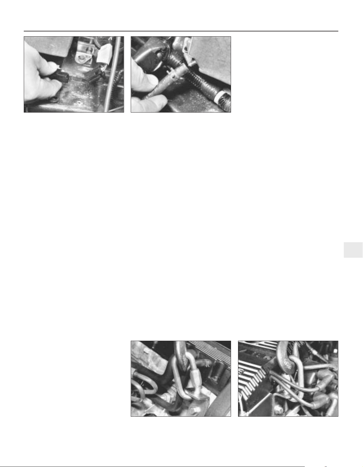
12 Trace the clutch cable back from the
clutch release lever to the bulkhead and
remove the C-clip which retains the outer
cable spring in position. Unhook the
inner cable from the release lever and free the
outer cable from its mounting bracket and
position it clear of the gearbox.
13 From underneath the vehicle, pull out the
rubber retaining pin which secures the lower
end of the speedometer cable to the gearbox
housing. Withdraw the cable from the
speedometer drive and remove the O-rings
from the cable lower end. Renew the O-rings,
regardless of their condition.
14 In the absence of the special gearchange
linkage balljoint separator (Rover service tool
number 18G 1592), use a suitable flat-bladed
screwdriver to carefully lever the link rod
balljoints off the gearbox upper and lower
selector levers, taking care not to damage the
balljoint gaiters.
15 Unscrew the reverse interlock cable nut
from the top of the gearbox housing. In the
absence of the special spanner (Rover service
tool number 18G 1591), use a close-fitting
spanner to unscrew the plastic nut, noting
that it is easily damaged. Plug the gearbox
orifice to prevent the entry of dirt.
16 Disconnect the coolant hose from the
bottom of the expansion tank, the expansion
tank hose from the inlet manifold union, both
heater hoses from the heater matrix unions
and the radiator top hose from the coolant
outlet elbow. Either remove the radiator
bottom hose or secure it so that it will not
hinder engine/gearbox removal.
17 Slacken and remove the union bolt which
secures the vacuum servo unit vacuum hose
to the inlet manifold. Discard the sealing
washers as they must be renewed whenever
they are disturbed.
18 On carburettor engines, disconnect the
feed hose from the fuel pump, then
disconnect the accelerator and choke cables
from the carburettor.
19 On fuel-injected engines, depressurise the
fuel system and disconnect the fuel feed and
return hoses from the throttle body/fuel rail.
Disconnect the accelerator cable from the
throttle housing.
20 Remove the expansion tank mounting
bolts and position the tank clear of the engine
unit.
21 Remove the alternator.
22 On models equipped with power-assisted
steering, remove the power steering pump.
23 On models equipped with air
conditioning, slacken and remove the two
compressor heatshield retaining bolts then
remove the heatshield and disconnect the
compressor wiring connector. Undo the four
bolts securing the compressor to the
mounting bracket and the single bolt securing
the air conditioning pipe to the mounting
bracket. Position the compressor clear of the
engine unit. Secure it to the body to avoid
placing any strain on the air conditioning
pipes and hoses.
24 Disconnect the exhaust system front pipe
from the manifold and, where necessary,
disconnect the lambda sensor wiring
connector.
25 Slacken and remove the bolt and washer
securing the anti-roll bar connecting link to
the left-hand lower suspension arm, then the
two bolts securing the tie bar to the lower
suspension arm.
26 Extract the split pins and undo the nuts
securing the steering gear track rod end
balljoint and the left-hand lower suspension
arm balljoint to the swivel hub. Remove the
nuts and release the balljoint tapered shanks
using a universal balljoint separator.
27 Insert a suitable flat bar in between the
left-hand inner constant velocity joint and
gearbox housing, then carefully lever the joint
out of position, whilst taking great care not to
damage the gearbox housing.
28 Withdraw the left-hand inner constant
velocity joint from the gearbox and support
the driveshaft to avoid damaging the constant
velocity joints or gaiters. Repeat the
operations described in paragraphs 25 to 28
for the right-hand driveshaft.
29 On K8 engines, the cylinder head has a
tapped hole provided at the right-hand rear
end (above the dipstick tube) and at the lefthand front end (behind the spark plug lead
clips). On K16 engine cylinder heads, the
right-hand end hole is in the same place but at
the left-hand end, the air intake duct support
bracket mounting points must be used.
Attach lifting brackets to the engine at these
points (see illustrations). Take the weight of
the engine/gearbox unit on the engine hoist.
30 From underneath the vehicle, unscrew the
two bolts securing the rear engine/gearbox
mounting bracket to the gearbox, then
slacken the connecting link-to-body throughbolt and pivot the mounting away from the
gearbox.
31 Slacken and remove the two bolts
securing the left-hand gearbox bracket to the
mounting. Lower the gearbox slightly then
undo the four bolts securing the mounting to
the body and manoeuvre the mounting out of
position.
32 Raise the gearbox again then slacken and
remove the right-hand engine/gearbox
mounting through-bolt and nut. Unscrew the
two nuts securing the mounting to the engine
bracket and remove it, noting the rubber
washers which are fitted on each side of the
bracket.
33 Make a final check that all components
have been removed or disconnected that will
prevent removal of the engine/gearbox unit
from the vehicle and ensure that components
such as the gearchange linkage link rods are
secured so that they cannot be damaged on
removal.
34 Lift the engine/gearbox unit out of the
vehicle, ensuring that nothing is trapped or
damaged. Once the unit is high enough, lift it
Engine removal and general overhaul procedures 2B•3
4.11c Disconnecting vacuum pipe from
engine management ECU - fuel-injected
engines
4.29b . . . and left-hand engine lifting
bracket - K16 engine
4.29a Right-hand engine lifting bracket . . .
4.11b . . . and ignition coil LT wiring
connector
2B
1689 Rover 214 & 414 Updated Version 09/97

out over the front of the body and lower the
unit to the ground (see illustration).
35 To separate the engine and gearbox, first
remove the starter motor.
36 Unbolt the flywheel front, lower and rear
cover plates, then unscrew the four bolts
securing the gearbox to the engine and gently
prise the gearbox off the two locating dowels
(at the front and rear of the main bearing
ladder). Move the gearbox squarely away
from the engine, ensuring that the clutch
components are not damaged.
37 If the engine is to be overhauled, remove
the clutch.
Refitting
38 Refitting is the reverse of removal,
following where necessary the instructions
given in the other Chapters of this Manual.
Note the following additional points:
a) Overhaul and lubricate the clutch
components before refitting.
b) When the gearbox, starter motor and
flywheel cover plates have been refitted,
lift the engine/gearbox unit and lower it
into the engine compartment so that it is
slightly tilted (gearbox down). Engage
both driveshafts then return the unit to the
horizontal and refit the engine/gearbox
mountings.
c) Remove the lifting brackets and refit any
components removed to enable them to
be fitted.
d) Tighten all nuts and bolts to the specified
torque wrench settings.
e) Adjust the choke and/or accelerator
cable(s).
f) Refill the engine and gearbox with oil.
g) Refill the cooling system.
5 Engine overhaul -
dismantling sequence
Note: When removing external components
from the engine, pay close attention to details
that may be helpful or important during
refitting. Note the fitted position of gaskets,
seals, spacers, pins, washers, bolts and other
small items.
1 It is much easier to work on the engine if it
is mounted on a portable engine stand. These
stands can often be hired from a tool hire
shop. Before the engine is mounted on a
stand, the flywheel should be removed so that
the stand bolts can be tightened into the end
of the cylinder block/crankcase (not the main
bearing ladder).
2 If a stand is not available, it is possible to
dismantle the engine with it blocked up on a
sturdy workbench or on the floor. Be extra
careful not to tip or drop the engine when
working without a stand.
3 If you are going to obtain a reconditioned
engine, all external components must be
removed for transference to the replacement
engine (just as if you are doing a complete
engine overhaul yourself). These components
include the following:
a) Alternator mounting brackets.
b) Power steering pump and air conditioning
compressor brackets (where fitted).
c) Distributor, HT leads and spark plugs.
d) Thermostat and housing, coolant rail,
coolant outlet elbow.
e) Dipstick tube.
f) Carburettor/fuel injection system
components.
g) All electrical switches and sensors.
h) Inlet and exhaust manifolds.
i) Oil filter.
j) Fuel pump.
k) Engine mountings.
l) Flywheel.
4 If you are obtaining a short motor (which
consists of the engine cylinder block/crankcase
and main bearing ladder, crankshaft, pistons
and connecting rods all assembled), then the
cylinder head, sump, oil pump, and timing belt
will have to be removed also.
5 If you are planning a complete overhaul, the
engine can be dismantled and the internal
components removed in the following order:
a) Inlet and exhaust manifolds.
b) Timing belt, sprockets, tensioner and
timing belt inner cover.
c) Cylinder head.
d) Flywheel.
e) Sump.
f) Oil pump.
g) Piston/connecting rod assemblies.
h) Crankshaft.
6 Before beginning the dismantling and
overhaul procedures, make sure that you have
all of the correct tools necessary. Refer to the
introductory pages at the beginning of this
Manual for further information.
6 Cylinder head - dismantling
3
Note: New and reconditioned cylinder heads
are available from the manufacturer and from
engine overhaul specialists. Due to the fact
that some specialist tools are required for
dismantling and inspection, and new
components may not be readily available, it
may be more practical and economical for the
home mechanic to purchase a reconditioned
head rather than dismantle, inspect and
recondition the original.
1 Remove the camshaft(s) and hydraulic
tappets.
2 Remove the cylinder head.
3 Using a valve spring compressor, compress
each valve spring in turn until the split collets
can be removed. Release the compressor and
lift off the spring retainer and spring, then use
a pair of pliers to extract the spring bottom
seat/stem seal (see illustrations).
4 Withdraw the valve through the combustion
chamber.
5 It is essential that each valve is stored
together with its collets, retainer and spring,
and that all valves are kept in their correct
sequence, unless they are so badly worn that
they are to be renewed. If they are going to be
kept and used again, place each valve
assembly in a labelled polythene bag or
2B•4 Engine removal and general overhaul procedures
6.3b Extracting a valve spring bottom
seat/stem seal
6.3a Using a valve spring compressor to
release split collets
4.34 Lifting out engine/gearbox unit
1689 Rover 214 & 414 Updated Version 09/97
If, when the valve spring
compressor is screwed
down, the spring retainer
refuses to free and expose
the split collets, gently tap the top of
the tool directly over the retainer with a
light hammer. This will free the
retainer.

similar small container (see illustration). Note
that No 1 valve is nearest to the timing belt
end of the engine.
7 Cylinder head and valves -
cleaning and inspection
4
Note: If the engine has been severely
overheated, it is best to assume that the
cylinder head is warped and to check carefully
for signs of this.
Note: Be sure to perform all the following
inspection procedures before concluding that
the services of a machine shop or engine
overhaul specialist are required. Make a list of
all items that require attention.
1 Thorough cleaning of the cylinder head and
valve components, followed by a detailed
inspection, will enable you to decide how
much valve service work must be carried out
during the engine overhaul.
Cleaning
2 Scrape away all traces of old gasket
material and sealing compound from the
cylinder head.
3 Scrape away all carbon from the
combustion chambers and ports, then wash
the cylinder head thoroughly with paraffin or a
suitable solvent.
4 Scrape off any heavy carbon deposits that
may have formed on the valves, then use a
power-operated wire brush to remove
deposits from the valve heads and stems.
Inspection
Cylinder head
5 Inspect the head very carefully for cracks,
evidence of coolant leakage and other
damage. If cracks are found, a new cylinder
head should be obtained.
6 Use a straight-edge and feeler gauge blade
to check that the cylinder head surface is not
distorted (see illustrations). If it is, it may be
possible to resurface it, provided that the
specified reface limit is not exceeded in so
doing, or that the cylinder head is not reduced
to less than the specified height.
7 Examine the valve seats in each of the
combustion chambers. If they are severely
pitted, cracked or burned, then they will need
to be renewed or re-cut by an engine overhaul
specialist. If they are only slightly pitted, this
can be removed by grinding-in the valve
heads and seats with fine valve-grinding
compound as described below. To check for
excessive wear, refit each valve and measure
the installed height of the stem tip above the
cylinder head upper surface (see illustration).
If the measurement is above the specified
limit, repeat the test using a new valve. If the
measurement is still excessive, renew the seat
insert.
8 If the valve guides are worn, indicated by a
side to side motion of the valve, new guides
must be fitted. Measure the diameter of the
existing valve stems (see below) and the bore
of the guides, then calculate the clearance
and compare the result with the specified
value. If the clearance is excessive, renew the
valves or guides as necessary.
9 Valve guide renewal is best carried out by
an engine overhaul specialist. If the work is to
be carried out at home, then use a stepped,
double-diameter drift to drive out the worn
guide towards the combustion chamber. On
fitting the new guide, place it first in a deepfreeze for one hour, then drive it into the
cylinder head bore from the camshaft side
until it projects the specified amount above
the spring bottom seat/stem seal surface.
10 If the valve seats are to be re-cut, this
must be done only after the guides have been
renewed.
Valves
11 Examine the head of each valve for
pitting, burning, cracks and general wear,
then check the valve stem for scoring and
wear ridges. Rotate the valve and check for
any obvious indication that it is bent. Look for
pits and excessive wear on the tip of each
valve stem. Renew any valve that shows any
such signs of wear or damage.
12 If the valve appears satisfactory at this
stage, measure the valve stem diameter at
several points by using a micrometer (see
illustration). Any significant difference in the
readings obtained indicates wear of the valve
stem. Should any of these conditions be
apparent, the valve(s) must be renewed.
13 If the valves are in satisfactory condition
they should be ground (lapped) into their
respective seats to ensure a smooth gas-tight
seal. If the seat is only lightly pitted, or if it has
been re-cut, fine grinding compound only
should be used to produce the required finish.
Coarse valve-grinding compound should not
be used unless a seat is badly burned or
deeply pitted. If this is the case, the cylinder
head and valves should be inspected by an
expert to decide whether seat re-cutting or
Engine removal and general overhaul procedures 2B•5
7.6a Checking a cylinder head gasket
surface for warpage
6.5 Use a labelled plastic bag to keep
together and identify valve components
7.12 Measuring valve stem diameter7.7 Check valve seat wear by measuring
valve stem installed height (A)
7.6b Check cylinder head gasket surface
for warpage along paths shown
A K16 engine B K8 engine
2B
1689 Rover 214 & 414 Updated Version 09/97
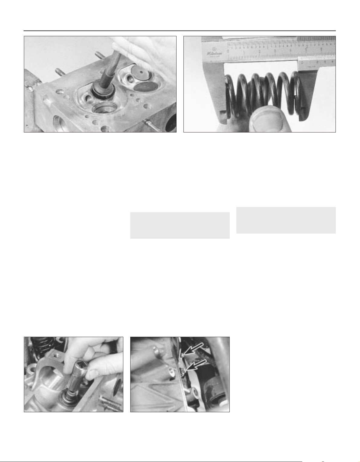
even the renewal of the valve or seat insert is
required.
14 Valve grinding is carried out as follows.
Place the cylinder head upside down on a
bench.
15 Smear a trace of (the appropriate grade of)
valve-grinding compound on the seat face and
press a suction grinding tool onto the valve
head. With a semi-rotary action, grind the valve
head to its seat, lifting the valve occasionally to
redistribute the grinding compound (see
illustration). A light spring placed under the
valve head will greatly ease this operation.
16 If coarse grinding compound is being
used, work only until a dull, matt even surface
is produced on both the valve seat and the
valve, then wipe off the used compound and
repeat the process with fine compound. When
a smooth unbroken ring of light grey matt
finish is produced on both the valve and seat,
the grinding operation is complete. Do not
grind in the valves any further than absolutely
necessary, or the seat will be prematurely
sunk into the cylinder head.
17 To check that the seat has not been overground, measure the valve stem installed
height, as described in paragraph 7.
18 When all the valves have been ground-in,
carefully wash off all traces of grinding
compound using paraffin or a suitable solvent.
Valve components
19 Examine the valve springs for signs of
damage and discoloration and also measure
their free length using vernier calipers or by
comparing each existing spring with a new
component (see illustration).
20 Stand each spring on a flat surface and
check it for squareness. If any of the springs
are damaged, distorted or have lost their
tension, then obtain a complete new set of
springs.
21 Check the hydraulic tappets as described
in Part A of this Chapter.
8 Cylinder head - reassembly
4
1 Lubricate the valve stems with clean engine
oil and insert each valve into its original
location. If new valves are being fitted, insert
them into the locations to which they have
been ground.
2 Working on the first valve, dip the spring
bottom seat/stem seal in clean engine oil then
carefully locate it over the valve and onto the
guide. Take care not to damage the seal as it
is passed over the valve stem. Use a suitable
socket or metal tube to press the seal firmly
onto the guide (see illustration).
3 Locate the spring on the seat, followed by
the spring retainer.
4 Compress the valve spring and locate the
split collets in the recess in the valve stem.
Use a little grease to hold the collets in place.
Release the compressor, then repeat the
procedure on the remaining valves.
5 With all the valves installed, place the
cylinder head flat on the bench and, using a
hammer and interposed block of wood, tap
the end of each valve stem to settle the
components.
6 Refit the hydraulic tappets and camshaft(s)
as described in Part A of this Chapter.
9 Piston/connecting rod
assembly - removal
4
Note: Due to the design of the engine, it will
become very difficult, almost impossible, to
turn the crankshaft once the cylinder head
bolts have been slackened. The manufacturer
accordingly states that the crankshaft will be
‘tight’ and should not be rotated more than
absolutely necessary once the head has been
removed. If the crankshaft cannot be rotated,
then it must be removed for overhaul work to
proceed. With this in mind, during any
servicing or overhaul work the crankshaft must
always be rotated to the desired position
before the bolts are disturbed.
Removal - without removing
crankshaft
1 Remove the timing belt, the camshaft
sprocket(s) and tensioner, and the timing belt
inner cover.
2 Remove the camshaft(s) and hydraulic
tappets, being careful to store the hydraulic
tappets correctly.
3 If the flywheel has been removed,
temporarily refit the crankshaft pulley and
apply a spanner to the bolt to rotate the
crankshaft.
4 Rotate the crankshaft until Nos 1 and 4
cylinder pistons are at the top of their stroke.
5 Remove the cylinder head. The crankshaft
cannot now be rotated.
6 Slacken and remove the two dipstick tube
retaining bolts and remove the tube from the
cylinder block/crankcase (see illustrations).
9.6a Dipstick tube mounting bolts
(arrowed)
2B•6 Engine removal and general overhaul procedures
8.2 Using a socket to install valve stem
seal
7.19 Measuring valve spring free length7.15 Grinding-in a valve seat
1689 Rover 214 & 414 Updated Version 09/97
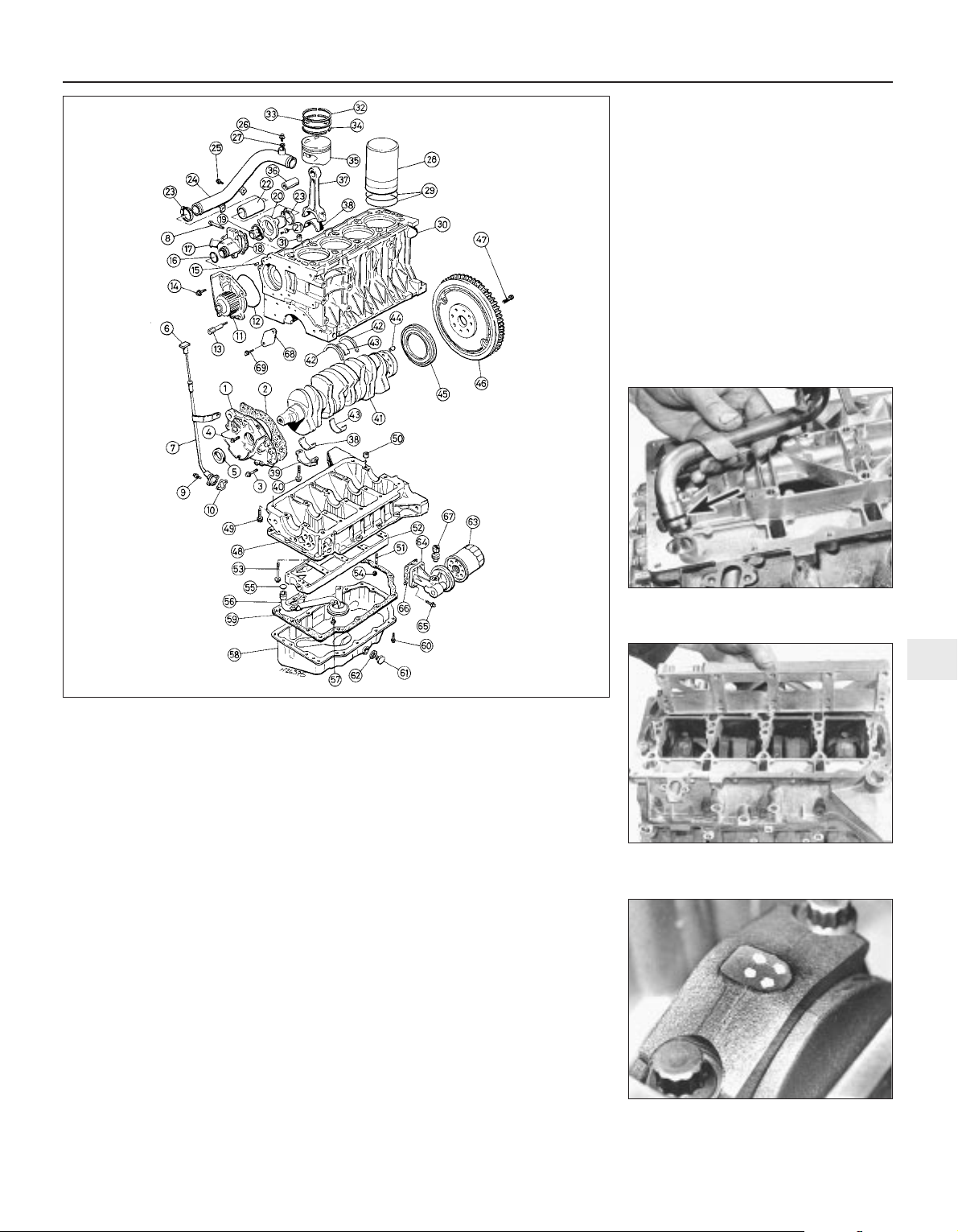
7 Remove the sump and unbolt the oil pump
pick-up/strainer pipe from the oil rail. Discard
the sealing ring (see illustration).
8 Unscrew the two retaining nuts and remove
the oil rail (see illustration).
9 Using a hammer and centre punch, paint or
similar, mark each connecting rod big-end
bearing cap with its respective cylinder
number on the flat, machined surface
provided. If the engine has been dismantled
before, note carefully any identifying marks
made previously (see illustration). Note that
No 1 cylinder is at the timing belt end of the
engine.
10 Unscrew and remove the big-end bearing
cap bolts and withdraw the cap, complete
with bearing shell, from the connecting rod. If
only the bearing shells are being attended to,
Engine removal and general overhaul procedures 2B•7
9.7 Removing oil pump pick-up/strainer
pipe from oil rail - renew O-ring (arrowed)
9.6b Engine bottom end components
1 Oil pump
2 Gasket
3 Bolt
4 Bolt
5 Oil seal
6 Engine oil level dipstick
7 Dipstick tube
8 Bolt
9 Bolt
10 Gasket
11 Coolant pump
12 O-ring
13 Pillar bolt
14 Bolt
15 Dowel pin
16 O-ring
17 Thermostat housing
18 Gasket
19 Thermostat
20 Thermostat housing
21 Bolt
22 Coolant hose
23 Hose clip
24 Coolant rail
25 Screw
26 Cooling system bleed
screw
27 Sealing washer
28 Liner
29 O-rings
30 Cylinder block/crankcase
31 Dowel
32 Top compression ring
33 Second compression
ring
34 Oil control ring
35 Piston
36 Gudgeon pin *
37 Connecting rod
38 Big-end bearing shell
39 Big-end bearing cap
40 Big-end bearing cap bolt
41 Crankshaft
42 Crankshaft thrustwasher
43 Crankshaft main bearing
shell
44 Dowel
45 Oil seal
46 Flywheel (with reluctor
ring)
47 Flywheel bolt
48 Main bearing ladder *
49 Bolt
50 Dowel
51 Stud
52 Oil rail
53 Bolt
54 Nut
55 O-ring
56 Oil pump pick-up/
strainer pipe
57 Bolt
58 Sump
59 Gasket
60 Bolt
61 Engine oil drain plug
62 Sealing washer
63 Oil filter
64 Oil filter adaptor
65 Bolt
66 Gasket
67 Oil pressure switch
68 Blanking plate -
carburettor engines
69 Screw
* Note: Main bearing ladder is
supplied only with cylinder
block/crankcase assembly.
Gudgeon pin is supplied only
with piston assembly
9.8 Removing oil rail to reach big-end
bearings
9.9 Mark big-end bearing caps before
removal - No 4 cylinder cap shown
2B
1689 Rover 214 & 414 Updated Version 09/97
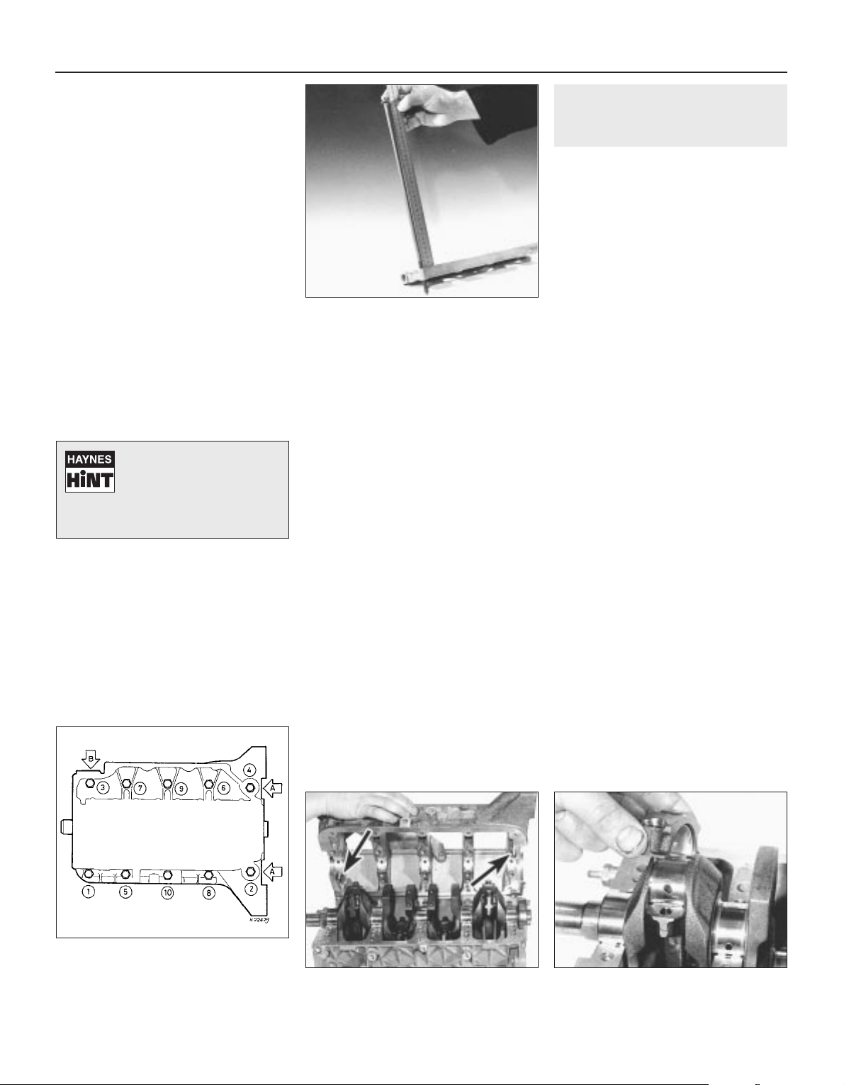
push the connecting rod up and off the
crankpin, ensuring that the connecting rod
big-ends do not mark the cylinder bore walls,
then remove the upper bearing shell. Keep the
cap, bolts and (if they are to be refitted) the
bearing shells together in their correct
sequence.
11 With Nos 2 and 3 cylinder big-ends
disconnected, repeat the procedure
(exercising great care to prevent damage to
any of the components) to remove Nos 1 and
4 cylinder bearing caps.
12 Remove the ridge of carbon from the top
of each cylinder bore. Push each
piston/connecting rod assembly up and
remove it from the top of the bore, and ensure
that the connecting rod big-ends do not mark
the cylinder bore walls.
13 Note that the number stamped by you on
each bearing cap should match the cylinder
number stamped on the front (alternator
bracket side) of each connecting rod. If any
connecting rod number does not match its
correct cylinder, mark or label it immediately
so that each piston/connecting rod assembly
can be refitted to its original bore.
Removal - alternative methods
14 If the engine is being completely
dismantled and the cylinder head has been
removed, either unbolt the main bearing
ladder so that the crankshaft can be rotated
with care, or remove the crankshaft
completely and then remove the connecting
rods and pistons.
Cylinder head bolts - condition
check
15 Check the condition of the cylinder head
bolts and particularly their threads whenever
they are removed. If the cylinder head only is
removed, check the bolts as described in
Part A of this Chapter. If the cylinder
head and the oil rail are removed, check as
follows.
16 Keeping all the bolts in their correct fitted
order, wash them and wipe dry, then check
each for any sign of visible wear or damage.
Renew any bolt if necessary. Lightly oil the
threads of each bolt, carefully enter it into the
original hole and screw it in, by hand only until
finger-tight. If the full length of thread is
engaged, the bolt may be re-used. If the
full length of thread is not engaged, measure
the distance from the oil rail gasket surface to
under the bolt head (see illustration).
17 If the distance measured is less than 378
mm, then the bolt may be re-used. If the
distance measured is more than 378 mm, the
bolt must be renewed. Considering the task
these bolts perform and the pressures they
must withstand, owners should consider
renewing all the bolts as a matched set if
more than one of the originals fail inspection
or are close to the limit set.
18 Note that if any of the cylinder head bolt
threads in the oil rail are found to be
damaged, then the oil rail must be renewed.
Thread inserts are not an acceptable repair in
this instance.
10 Crankshaft - removal
4
Note: The following procedure assumes that
the crankshaft alone is being removed and
therefore uses a slightly different sequence of
operations to that given in Section 9.
Depending on the reason for dismantling,
either sequence may be adapted as
necessary. If the crankshaft endfloat is to be
checked, this must be done when the
crankshaft is free to move. If a dial gauge is to
be used, check after paragraph 1, but if feeler
gauges are to be used, check after paragraph 9.
1 Remove the timing belt, sprocket(s)
and tensioner, and the timing belt inner
cover.
2 Slacken and remove the two dipstick tube
retaining bolts and remove it from the cylinder
block/crankcase.
3 Remove the cylinder head. The crankshaft
cannot now be rotated.
4 Remove the oil pump.
5 Remove the crankshaft left-hand oil seal.
6 Remove the sump and unbolt the oil pump
pick-up/strainer pipe from the oil rail. Discard
the sealing ring.
7 Unscrew the two retaining nuts and remove
the oil rail.
8 Working in the sequence shown (see
illustration), progressively unscrew the main
bearing ladder retaining bolts by a turn at a
time, then withdraw the ladder. Note the two
locating dowels and the main bearing shells,
which should be removed from the ladder and
stored in their correct fitted order (see
illustration).
9 Mark the big-end bearing caps, then
unscrew and remove the big-end bearing cap
bolts and withdraw the cap, complete with the
lower bearing shell, from each of the four
connecting rods (see illustration). Push
the connecting rods up and off their
crankpins, then remove the upper bearing
shell. Keep the cap, bolts and (if they are to be
refitted) the bearing shells together in their
correct sequence.
2B•8 Engine removal and general overhaul procedures
10.9 Removing No 1 cylinder big-end
bearing cap and lower bearing shell
10.8b Removing main bearing ladder (two
locating dowels arrowed)
10.8a Crankshaft main bearing ladder bolt
slackening sequence
A Bolts hidden in ladder flanges
B Location of single longer bolt
9.16 Checking length of cylinder head
bolts
1689 Rover 214 & 414 Updated Version 09/97
Fit the bearing cap, shells
and bolts to each removed
piston/connecting rod
assembly, so that they are
all kept together as a
matched set.

10 Remove the crankshaft (see illustration).
11 Withdraw the two thrustwashers from the
No 3 main bearing upper location. Noting the
position of the grooved shells, remove the
upper main bearing shells, which must be
kept with their correct respective partners
from the main bearing ladder so that all shells
can be identified and (if necessary) refitted in
their original locations.
12 Check the condition of the cylinder head
bolts, as described in Section 9.
11 Cylinder block/crankcase -
cleaning and inspection
4
Warning: Wear eye protection
when using compressed air!
Note: During any cleaning operations, take
care not to score the mating surfaces of the
cylinder block/crankcase, bearing ladder and
oil rail. It may be necessary to use a foam
action gasket remover.
Cleaning
1 For complete cleaning, remove the cylinder
liners, all external components and all
electrical switches/sensors.
2 Scrape all traces of gasket from the cylinder
block/crankcase, bearing ladder and oil rail,
taking care not to damage the gasket/sealing
surfaces.
3 Remove all oil gallery plugs (where fitted).
The plugs are usually very tight and may have
to be drilled out and the holes re-tapped. Use
new plugs when the engine is reassembled.
4 If any of the castings are extremely dirty, all
should be steam cleaned.
5 After the castings are returned, clean all oil
holes and oil galleries one more time. Flush all
internal passages with warm water until the
water runs clear, then dry thoroughly and
apply a light film of oil to all liner surfaces to
prevent rusting. If you have access to
compressed air, use it to speed up the drying
process and to blow out all the oil holes and
galleries.
6 If the castings are not very dirty, you can do
an adequate cleaning job with hot soapy
water and a stiff brush. Take plenty of time
and do a thorough job. Regardless of the
cleaning method used, be sure to clean all oil
holes and galleries very thoroughly and to dry
all components well. Protect the liners as
described above to prevent rusting.
7 All threaded holes must be clean to ensure
accurate torque readings during reassembly.
To clean all threads except those of the
flywheel retaining bolts, run the proper size
tap into each of the holes to remove rust,
corrosion, thread sealant or sludge and to
restore damaged threads. If possible, use
compressed air to clear the holes of debris
produced by this operation. A good
alternative is to inject aerosol-applied waterdispersant lubricant into each hole, using the
long spout usually supplied. Always wear eye
protection when cleaning out holes in this
way. The flywheel retaining bolt threads must
be cleaned by using the procedure described
in Section 18, in Part A of this Chapter. Now is
a good time to check the condition of the
cylinder head bolts.
8 Apply suitable sealant to the new oil gallery
plugs and insert them into the holes in the
block. Tighten them securely.
9 If the engine is not going to be reassembled
right away, cover it with a large plastic bag to
keep it clean. Protect the liners as described
above to prevent rusting.
Inspection
10 Inspect all castings for cracks and
corrosion. Look for stripped threads. If there
has been any history of internal coolant
leakage, it may be worthwhile having an
engine overhaul specialist check the cylinder
block/crankcase with special equipment. If
defects are found, have them repaired, if
possible, or renew the assembly.
11 Check the bore of each cylinder liner for
scuffing and scoring.
12 Measure the diameter of each cylinder
liner bore 60 mm from the top of the bore,
both parallel to the crankshaft axis and at right
angles to it.
13 Compare the diameter with that specified.
If any measurement exceeds the service limit
then the liner must be renewed.
14 Measure the piston diameter at right
angles to the gudgeon pin axis, 16 mm up
from the bottom of the skirt. Compare the
results with those specified.
15 To measure the piston-to-bore clearance,
either measure the bore and piston skirt as
described above and subtract the skirt
diameter from the bore measurement, or
insert each piston into the original bore, select
a feeler gauge and slip it into the bore along
with the piston. The piston must be aligned
exactly in its normal attitude and the feeler
gauge must be between the piston and bore
on one of the thrust faces, 20 mm up from the
bottom of the bore.
16 If the clearance is excessive, then a new
piston will be required. If the piston binds
at the lower end of the bore and is loose
towards the top, then the bore is tapered. If
tight spots are encountered as the
piston/feeler gauge is rotated in the bore, then
the bore is out-of-round.
17 Repeat this procedure for the remaining
pistons and cylinder liners.
18 If the cylinder liner walls are badly scuffed
or scored, or if they are excessively worn, outof-round or tapered, obtain new cylinder
liners. New pistons will also be required.
19 If the bores are in reasonably good
condition and not worn to the specified limits,
and if the piston-to-bore clearances can be
maintained properly, then it may only be
necessary to renew the piston rings.
20 If this is the case, the bores should be
honed to allow the new rings to bed in
correctly and provide the best possible seal.
The conventional type of hone has springloaded stones and is used with a power drill.
You will also need some paraffin, or honing
oil, and rags. The hone should be moved up
and down the bore to produce a crosshatch
pattern and plenty of honing oil should be
used. Ideally the crosshatch lines should
intersect at approximately a 60° angle. Do not
take off more material than is necessary to
produce the required finish. If new pistons are
being fitted, the piston manufacturers may
specify a finish with a different angle, so their
instructions should be followed. Do not
withdraw the hone from the bore while it is still
being turned, but stop it first. After honing a
bore, wipe out all traces of the honing oil. If
equipment of this type is not available, or if
you are not sure whether you are competent
to undertake the task yourself, an engine
overhaul specialist will carry out the work at
moderate cost.
12 Cylinder liners -
removal and refitting
Removal
1 Invert the cylinder block/crankcase and
support it on blocks of wood, then use a hard
wood drift to tap out each liner from the
crankshaft side. When all the liners are
released, tip the cylinder block/crankcase on
its side and remove each liner from the
cylinder head side. Discard the two sealing
rings from the base of each. If the liners are to
be re-used, mark each one by sticking
masking tape on its right-hand (timing belt)
face and writing the cylinder number on the
tape.
Refitting
2 To install the liners, thoroughly clean the
liner mating surfaces in the cylinder
block/crankcase and use fine abrasive paper
to polish away any burrs or sharp edges
which might damage the liner sealing rings.
Clean the liners and wipe dry, then fit new
sealing rings to the two grooves at the base of
each liner and apply a thin film of oil to the
Engine removal and general overhaul procedures 2B•9
10.10 Removing the crankshaft
2B
1689 Rover 214 & 414 Updated Version 09/97
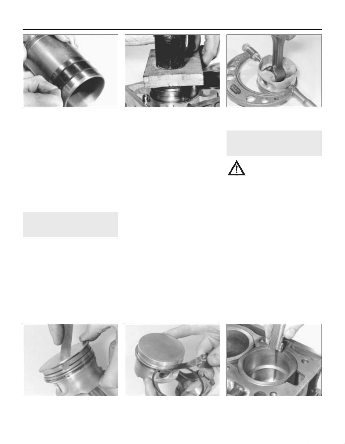
rings and to the liner surface on each side of
the rings (see illustration).
3 If the original liners are being refitted, use
the marks made on removal to ensure that
each is refitted the same way round into its
original bore. Insert each liner into the cylinder
block/crankcase, taking great care not to
displace or damage the sealing rings, and
press it home as far as possible by hand.
Using a hammer and a block of wood, tap
each liner lightly but fully onto its locating
shoulder (see illustration). Wipe clean, then
lightly oil all exposed liner surfaces to prevent
rusting.
13 Piston/connecting rod
assembly - inspection
3
1 Examine all pistons for ovality, scoring and
scratches, and for wear of the piston ring
grooves. Use a micrometer to measure the
pistons (see illustration).
2 If the pistons or connecting rods are to be
renewed, it is necessary to have this work
carried out by a Rover dealer or suitable
engine overhaul specialist who will have the
necessary tooling to remove and install the
gudgeon pins.
3 If new rings are to be fitted to the original
pistons, expand the old rings over the top of
the pistons. The use of two or three old feeler
gauge blades will be helpful in preventing the
rings dropping into empty grooves (see
illustration).
4 When the original piston rings have been
removed, ensure that the ring grooves in the
piston are free of carbon by cleaning them
with a ring cleaning tool or an old ring. Break a
ring in half to do this.
5 When measuring new rings, lay out each
piston set with a piston/connecting rod
assembly and keep them together as a
matched set from now on.
6 Check the ring-to-groove clearance by
inserting each ring from the outside together
with a feeler gauge blade between the ring’s
top surface and the piston land. Check the
ring end gaps by inserting each ring into the
cylinder bore and pushing it in with the piston
crown to ensure that it is square in the bore,
20 mm from the top. Use feeler gauges to
measure the gap (see illustrations).
7 If the end gap of a new ring is found to be
too large or too small, double-check to ensure
that you have the correct rings. If the end gap
is still too small, it must be opened up by
careful filing of the ring ends using a fine file. If
it is too large, this is not as serious unless the
specified service limit is exceeded, in which
case very careful checking is required of the
dimensions of all components as well as of
the new parts.
8 Note that each piston should be considered
as being matched to its respective liner and
they must not be interchanged.
14 Crankshaft - inspection
3
Warning: Wear eye protection
when using compressed air! Be
sure to clean oil holes with a
pipe cleaner or similar probe.
Checking endfloat
1 If crankshaft endfloat is to be checked, this
must be done when the crankshaft is still
installed in the cylinder block/crankcase but is
free to move.
2 Check endfloat by using a dial gauge in
contact with the end of the crankshaft. Push
the crankshaft fully one way and then zero the
gauge. Push the crankshaft fully the other way
and check the endfloat. The result can be
compared with the specified amount and will
give an indication as to whether new
thrustwashers are required.
3 If a dial gauge is not available, feeler
gauges can be used. First push the crankshaft
fully towards the flywheel end of the engine,
then use feeler gauges to measure the gap
between the web of No 3 crankpin and the
thrustwasher.
Inspection
4 Clean the crankshaft and dry it with
compressed air, if available.
5 Check the main and crankpin (big-end)
2B•10 Engine removal and general overhaul procedures
13.5b Measuring piston ring end gap13.5a Measuring piston ring-to-groove
clearance
13.3 Removing piston rings with feeler
blades
13.1 Measuring piston diameter12.3 Tap liner onto locating shoulder -
ensuring O-rings are not displaced
12.2 Renew liner O-rings
1689 Rover 214 & 414 Updated Version 09/97

bearing journals for uneven wear, scoring,
pitting and cracking.
6 Rub a penny across each journal several
times. If a journal picks up copper from the
penny, it is too rough (see illustration).
7 Remove any burrs from the crankshaft oil
holes with a stone, file or scraper.
8 Using a micrometer, measure the diameter
of the main bearing and crankpin (big-end)
journals and compare the results with those
specified (see illustration). Check carefully
that each journal’s diameter is within the
tolerances of the size grade corresponding to
the code number on the crankshaft right-hand
web (main bearing) or indicated by the code
letter on the left-hand web (crankpin/big-end
bearing). If any diameter measured is
incorrect for the grade indicated, re-check the
measurement carefully. If the journal is fit for
further service, the correct grade code should
be substituted when selecting new bearing
shells.
9 By measuring the diameter at a number of
points around each journal’s circumference,
you will be able to determine whether or not
the journal is out-of-round. Take the
measurement at each end of the journal (near
the webs) to determine if the journal is
tapered.
10 If the crankshaft journals are damaged,
tapered, out-of-round or worn beyond the
limits specified, the crankshaft must be
renewed unless an engine overhaul
specialist can be found who will regrind it and
supply the necessary undersize bearing
shells.
11 Check the oil seal journals at each end of
the crankshaft for wear and damage. If either
seal has worn an excessive groove in its
journal, consult an engine overhaul specialist
who will be able to advise whether a repair is
possible or whether a new crankshaft is
necessary.
15 Main and big-end bearings -
inspection
3
1 Even though the main and big-end bearings
should be renewed during the engine
overhaul, the old bearings should be retained
for close examination, as they may reveal
valuable information about the condition of
the engine. The bearing shells are graded by
thickness, the grade of each shell
being indicated by the colour code marked on
it.
2 Bearing failure occurs because of lack of
lubrication, the presence of dirt or other
foreign particles, overloading the engine and
corrosion. Regardless of the cause of bearing
failure, it must be corrected before the engine
is reassembled to prevent it from happening
again (see illustration).
3 When examining the bearing shells, remove
them from the cylinder block/crankcase, the
main bearing ladder, the connecting rods and
the connecting rod big-end bearing caps,
then lay them out on a clean surface in the
same general position as their location in the
engine. This will enable you to match any
bearing problems with the corresponding
crankshaft journal. Do not touch any shell’s
bearing surface with your fingers while
checking it, or the delicate surface may be
scratched.
4 Dirt and other foreign particles get into the
engine in a variety of ways. It may be left in
the engine during assembly, or it may pass
through filters or the crankcase ventilation
system. It may get into the oil and from there
into the bearings. Metal chips from machining
operations and normal engine wear are often
present. Abrasives are sometimes left in
engine components after reconditioning,
especially when parts are not thoroughly
cleaned by using the proper cleaning
methods. Whatever the source, these foreign
objects often end up embedded in the soft
bearing material and are easily recognized.
Large particles will not embed in the bearing
but will score or gouge the bearing and
journal. The best prevention for this cause of
bearing failure is to clean all parts thoroughly
and keep everything spotlessly clean
during engine assembly. Frequent and regular
engine oil and filter changes are also
recommended.
5 Lack of lubrication (or lubrication
breakdown) has a number of interrelated
causes. Excessive heat (which thins the oil),
overloading (which squeezes the oil from
the bearing face) and oil leakage (from
excessive bearing clearances, worn oil pump
or high engine speeds) all contribute to
lubrication breakdown. Blocked oil passages,
which usually are the result of misaligned oil
holes in a bearing shell, will also oil starve a
bearing and destroy it. When lack of
lubrication is the cause of bearing failure, the
bearing material is wiped or extruded from the
steel backing of the bearing. Temperatures
may increase to the point where the steel
backing turns blue from overheating.
6 Driving habits can have a definite effect on
bearing life. Full throttle, low speed operation
(labouring the engine) puts very high loads on
bearings, which tends to squeeze out the oil
film. These loads cause the bearings to flex,
which produces fine cracks in the bearing
face (fatigue failure). Eventually, the bearing
material will loosen in pieces and tear away
from the steel backing. Short-distance driving
leads to corrosion of bearings because
insufficient engine heat is produced to drive
off the condensed water and corrosive gases.
These products collect in the engine oil,
forming acid and sludge. As the oil is carried
to the engine bearings, the acid attacks and
corrodes the bearing material.
7 Incorrect bearing installation during engine
assembly will lead to bearing failure as well.
Tight fitting bearings leave insufficient bearing
running clearance and will result in oil
starvation. Dirt or foreign particles trapped
behind a bearing shell result in high spots on
the bearing which lead to failure. Do not touch
any shell’s bearing surface with your fingers
during reassembly as there is a risk of
scratching the delicate surface or of
depositing particles of dirt on it.
Engine removal and general overhaul procedures 2B•11
15.2 Typical bearing shell failures
14.8 Measuring crankshaft journal
diameter
14.6 Using a penny to check crankshaft
journal condition
2B
1689 Rover 214 & 414 Updated Version 09/97
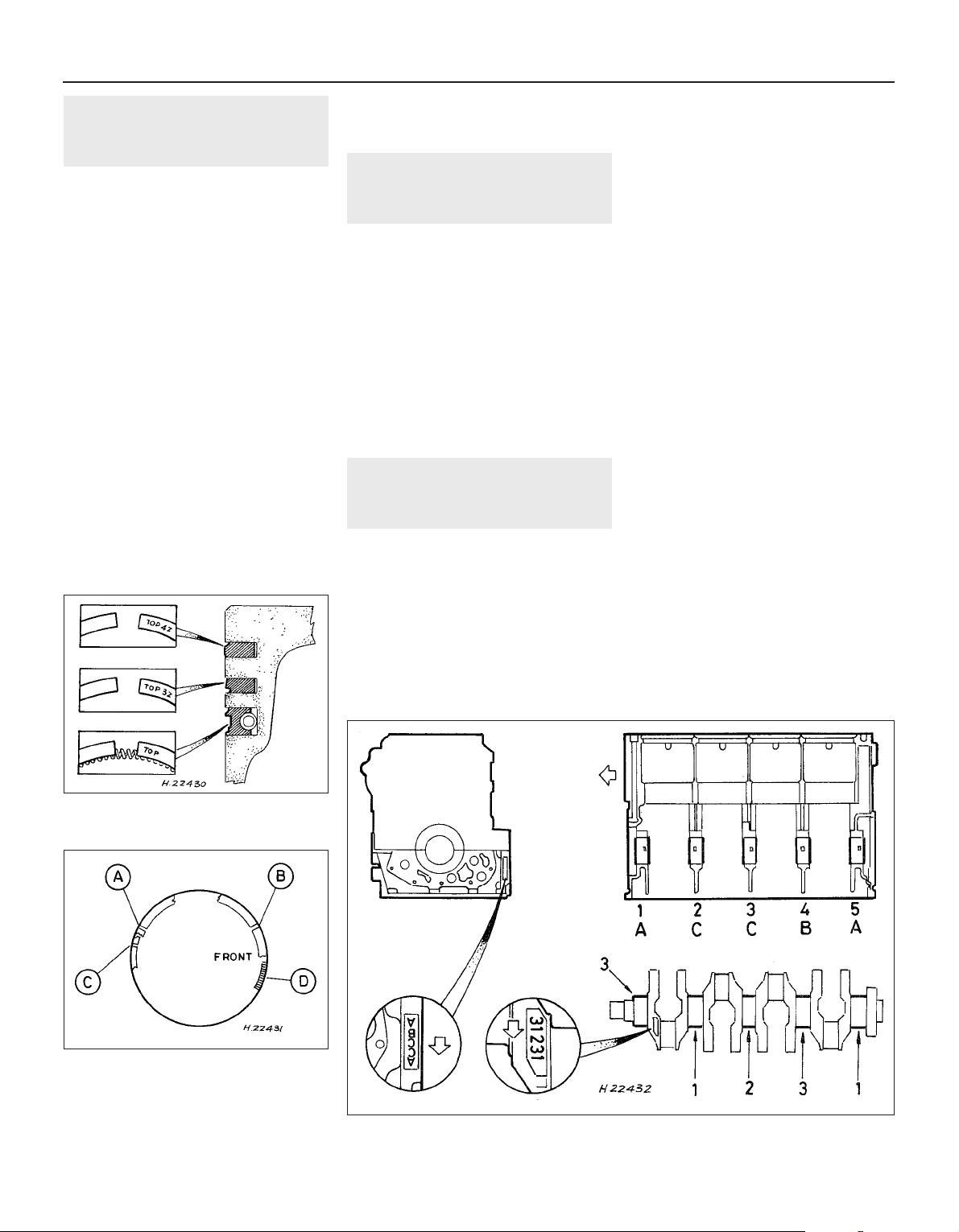
16 Engine overhaul -
reassembly sequence
1 Before reassembly begins, ensure that all
new parts have been obtained and that all
necessary tools are available. Read through
the entire procedure to familiarise yourself
with the work involved and to ensure that all
items necessary for reassembly of the engine
are at hand. In addition to all normal tools and
materials, it will be necessary to obtain the
Rover sealant kit LVV 10002. Carefully read
the instructions supplied with the sealant kit
and take care not to allow the sealant to
contact the fingers, as it will bond skin.
2 In order to save time and avoid problems,
engine reassembly can be carried out in the
following order:
a) Crankshaft.
b) Piston/connecting rod assemblies.
c) Oil pump.
d) Sump.
e) Flywheel.
f) Cylinder head.
g) Timing belt inner cover, tensioner and
sprockets, and timing belt.
h) Engine external components.
3 At this stage, all engine components should
be absolutely clean and dry, with all faults
repaired, and should be laid out (or in
individual containers) on a completely clean
work surface.
17 Piston rings - refitting
3
1 Refer to Section 13 for inspection details.
2 Once all rings have been checked, they can
be installed. Ensure that each ring is refitted
only to its matched piston and bore.
3 Install the new rings by fitting them over the
top of the piston, starting with the oil control
ring spring. Note that all rings must be fitted
with the word TOP uppermost (see
illustration).
4 With all the rings in position, space the ring
gaps as shown (see illustration), noting that
the FRONT marking shown is usually in fact
an arrow mark on the piston crown and
indicates the timing belt end of the engine.
18 Crankshaft - refitting and
main bearing running
clearance check
4
Selection of bearing shells
1 The main bearing running clearance is
controlled in production by selecting one of
three grades of bearing shell. The grades are
indicated by a colour-coding marked on the
edge of each shell which governs the shell’s
thickness, as follows:
a) Green - Thin.
b) Blue - Intermediate.
c) Red - Thick.
2 If shells of differing grades are to be fitted
to the same journal, the thicker shell must
always be fitted to the main bearing ladder
location. Bear this carefully in mind when
ordering replacement shells for Nos 2, 3 and 4
bearings.
3 If the bearing shells are to be renewed, first
check and record the main bearing code
letters stamped on the right-hand front face of
the main bearing ladder (see illustration). The
letters are read with the ladder inverted, No 1
bearing’s code letter then being at the top and
the remainder following in order from the
engine’s timing belt end.
4 Secondly, check and record the crankshaft
journal code numbers stamped on the
crankshaft’s right-hand web, No 1 journal’s
code number being the first. If the original
crankshaft is to be re-used, the size grade can
be checked by direct measurement, as
described in Section 14.
5 Note that if the crankshaft is found to be
excessively worn, then it must be renewed
and the code numbers of the new component
must be used instead to select a new set of
bearing shells.
6 Matching the codes noted to the following
table, select a new set of bearing shells.
Ladder code Crankshaft
letter code number Shells
A 1 Blue, Blue
A 2 Red, Blue
A 3 Red, Red
B 1 Blue, Green
B 2 Blue, Blue
B 3 Red, Blue
C 1 Green, Green
C 2 Blue, Green
C 3 Blue, Blue
2B•12 Engine removal and general overhaul procedures
18.3 Crankshaft main bearing size code locations
17.4 Piston ring end gap locations
A Top compression ring
B Second compression ring
C Oil control ring
D Oil control ring spring
17.3 Piston ring fitting details and top
surface markings
1689 Rover 214 & 414 Updated Version 09/97

Main bearing running clearance
check
7 Clean the backs of the bearing shells
and the bearing locations in both the
cylinder block/crankcase and the main
bearing ladder.
8 Press the bearing shells into their locations,
ensuring that the tab on each shell engages in
the notch in the cylinder block/crankcase or
main bearing ladder location. Take care not to
touch any shell bearing surface with your
fingers.
9 Press the bearing shells with the oil grooves
into the upper locations (in the cylinder
block/crankcase). Note the following points
(see illustration):
a) On all engines, grooved bearing shells are
fitted to Nos 2, 3 and 4 upper bearing
locations. Note the central locating tabs
of the grooved shells.
b) On early engines, grooved bearing shells
were fitted only to Nos 2 and 4 upper
bearing locations at the factory. On
reassembly of one of these units, a
grooved shell must be fitted at No 3
upper bearing location as well, instead of
the plain item originally used. Note,
however, that this will require a grooved
shell with an offset locating tab instead of
the central tab that is used on all other
grooved shells. See your Rover dealer for
details.
c) If bearing shells of differing grades are to
be fitted to the same journal, the thicker
shell must always be fitted to the main
bearing ladder location (see paragraph 1).
d) On all engines, if the original main bearing
shells are being re-used, these must be
refitted to their original locations in the
cylinder block/crankcase and main
bearing ladder.
10 The main bearing running clearance
should be checked if there is any doubt about
the amount of crankshaft wear that has taken
place, if the crankshaft has been reground
and is to be refitted with non-Rover
undersized bearing shells, or if non-genuine
bearing shells are to be fitted. If the original
crankshaft or a Rover replacement part is to
be installed, the shell selection procedure
given above will produce the correct
clearances and a further check will not be
necessary. If the clearance is to be checked, it
can be done in either of two ways.
11 The first method (which will be difficult to
achieve without a range of internal
micrometers or internal/external expanding
calipers) is to refit the main bearing ladder to
the cylinder block/crankcase, with bearing
shells in place. With the ladder retaining bolts
tightened to the specified torque, refit the oil
rail and the cylinder head, then measure the
internal diameter of each assembled pair of
bearing shells. If the diameter of each
corresponding crankshaft journal is measured
and then subtracted from the bearing internal
diameter, the result will be the main bearing
running clearance.
12 The second (and more accurate) method
is to use product known as Plastigauge. This
consists of a fine thread of perfectly round
plastic which is compressed between the
bearing shell and the journal. When the shell is
removed, the plastic is deformed and can be
measured with a special card gauge supplied
with the kit. The running clearance is
determined from this gauge. Plastigauge is
sometimes difficult to obtain but enquiries at
one of the larger specialist quality motor
factors should produce the name of a stockist
in your area. The procedure for using
Plastigauge is as follows.
13 With the main bearing upper shells in
place, carefully lay the crankshaft in position.
Do not use any lubricant. The crankshaft
journals and bearing shells must be perfectly
clean and dry.
14 Cut several lengths of the appropriate size
Plastigauge (they should be slightly shorter
than the width of the main bearings) and place
one length on each crankshaft journal axis
(see illustration).
15 With the main bearing lower shells in
position, refit the main bearing ladder (see
below) and the oil rail, tightening the fasteners
to the specified torque wrench settings. Take
care not to disturb the Plastigauge.
16 Refit the cylinder head (using the original
gasket, to save over-compressing the new
one). Tighten the bolts to the specified torque
in the approved sequence. Do not rotate the
crankshaft at any time during this operation.
17 Remove the cylinder head, the oil rail and
the main bearing ladder. Do not disturb the
Plastigauge or rotate the crankshaft.
18 Compare the width of the crushed
Plastigauge on each journal to the scale
printed on the Plastigauge envelope to obtain
the main bearing running clearance (see
illustration).
19 If the clearance is not as specified, the
bearing shells may be the wrong grade (or
excessively worn if the original shells are being
re-used). Before deciding that different grade
shells are needed, make sure that no dirt or oil
was trapped between the bearing shells and
the ladder or cylinder block/crankcase when
the clearance was measured. If the
Plastigauge was wider at one end than at the
other, the journal may be tapered.
20 Carefully scrape away all traces of the
Plastigauge material from the crankshaft and
bearing shells using a fingernail or other
object which is unlikely to score the shells.
Final crankshaft refitting
21 Carefully lift the crankshaft out of the
cylinder block once more.
22 Using a little grease, stick the
thrustwashers to each side of the No 3 main
bearing upper location. Ensure that the oilway
grooves on each thrustwasher face outwards.
23 Place the bearing shells in their locations,
as described in paragraphs 7 to 9. If new
shells are being fitted, ensure that all traces of
the protective grease are cleaned off using
paraffin. Wipe dry the shells and connecting
rods with a lint-free cloth. Liberally lubricate
each bearing shell in the cylinder
block/crankcase, then lower the crankshaft
into position so that Nos 2 and 3 cylinder
crankpins are at TDC.
24 Refit the piston/connecting rod
Engine removal and general overhaul procedures 2B•13
18.18 Using scale on Plastigauge envelope
to check (at widest point) width of crushed
Plastigauge
18.14 Lay length of Plastigauge on journal
to be measured, parallel to crankshaft
centre-line
18.9 Ensure grooved bearing shells
(arrowed) are installed exactly as
described in text - early engine shown
2B
1689 Rover 214 & 414 Updated Version 09/97
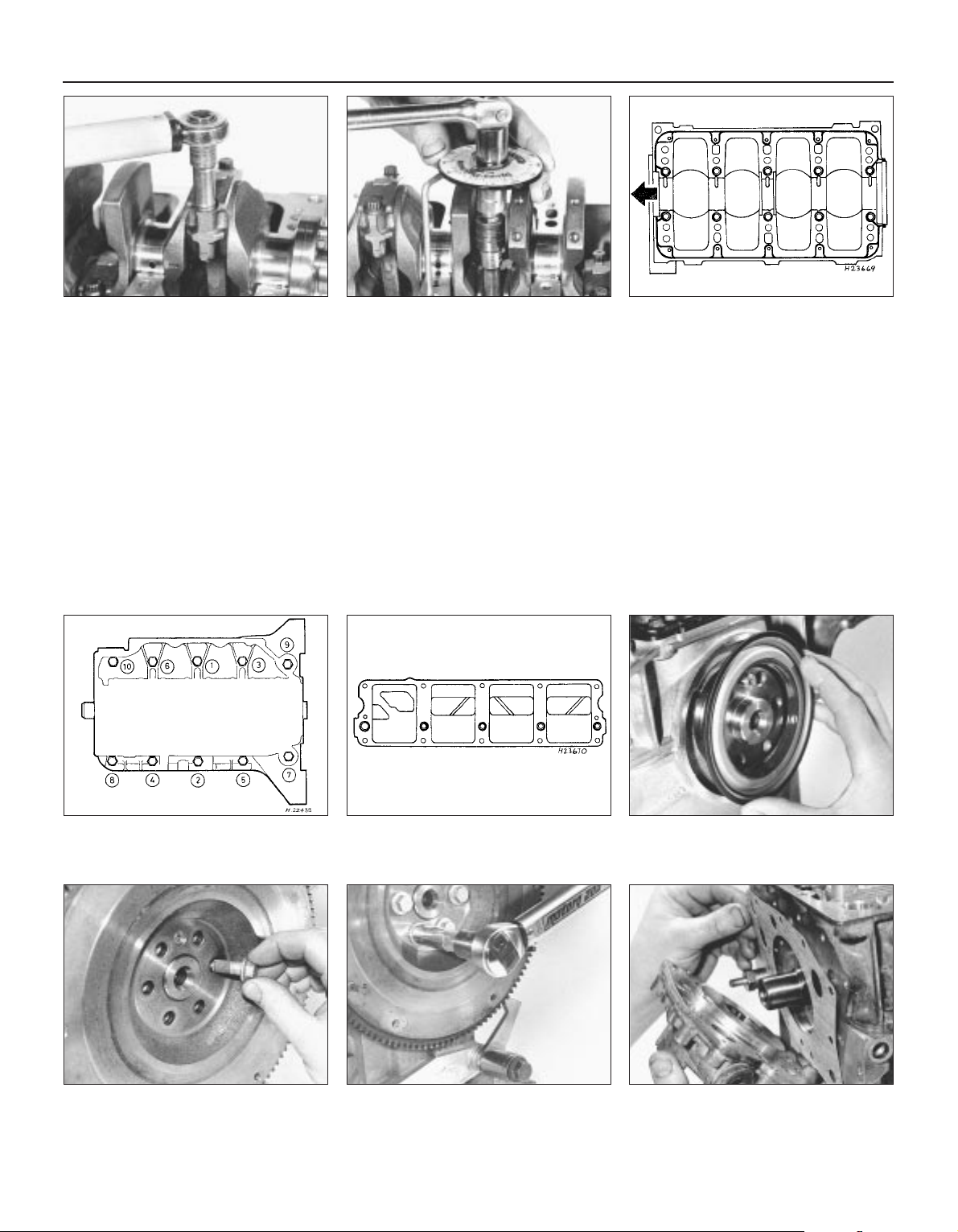
assemblies (see illustrations) . Leave No 1
and 4 cylinders at the TDC position
25 Thoroughly degrease the mating surfaces
of the cylinder block/crankcase and the main
bearing ladder. Apply the special Rover
sealant to the mating surface of the cylinder
block/crankcase as shown (see illustration).
Carefully follow the instructions supplied with
the sealant kit. If the Rover sealant is being
used, assembly must be completed as soon
as possible after the sealant has been applied
(maximum of 20 minutes). If another sealant is
being used, follow the manufacturer’s
instructions.
26 Lubricate the bearing shells, then refit the
main bearing ladder, ensuring that the shells
are not displaced and that the locating dowels
engage correctly. Working progressively, by a
turn at a time and in the sequence shown (see
illustration), tighten the ladder bolts to the
specified torque wrench setting. The
crankshaft cannot now be rotated.
27 Thoroughly degrease the mating surfaces
of the oil rail and the main bearing ladder.
Apply the special Rover sealant to the oil rail
mating surface as shown (see illustration).
Carefully follow the instructions supplied with
the sealant kit.
28 Refit the oil rail, tightening the nuts to the
specified torque wrench setting.
29 Using a new sealing ring, refit the oil
pump pick-up/strainer pipe to the oil rail, then
refit the sump. Tighten all nuts and bolts to
the specified torque wrench settings.
30 Fit a new crankshaft left-hand oil seal,
then refit the flywheel (see illustrations).
31 Refit the oil pump and install a new
crankshaft right-hand oil seal (see
illustrations).
32 Refit the cylinder head. Rotate the
crankshaft to the 90° BTDC position so that
the crankshaft sprocket timing marks align.
2B•14 Engine removal and general overhaul procedures
18.31a Use grease to stick new gasket in
place when refitting oil pump
18.30c Use fabricated tool to lock flywheel
while slackening or tightening flywheel
bolts
18.30b Always use new bolts when
refitting flywheel
18.30a Fitting a new crankshaft left-hand
oil seal
18.27 Apply thin bead of sealant to oil rail
mating surface as shown by heavy black
lines, then spread to an even film
18.26 Crankshaft main bearing ladder bolt
tightening sequence
18.25 Apply thin bead of sealant to
cylinder block/crankcase mating surface
along paths shown by heavy black lines,
then spread to an even film
18.24b . . . care is required to hold
crankshaft steady while connecting rod
big-end cap bolts are tightened
18.24a If piston/connecting rod
assemblies are refitted before main
bearing ladder . . .
1689 Rover 214 & 414 Updated Version 09/97
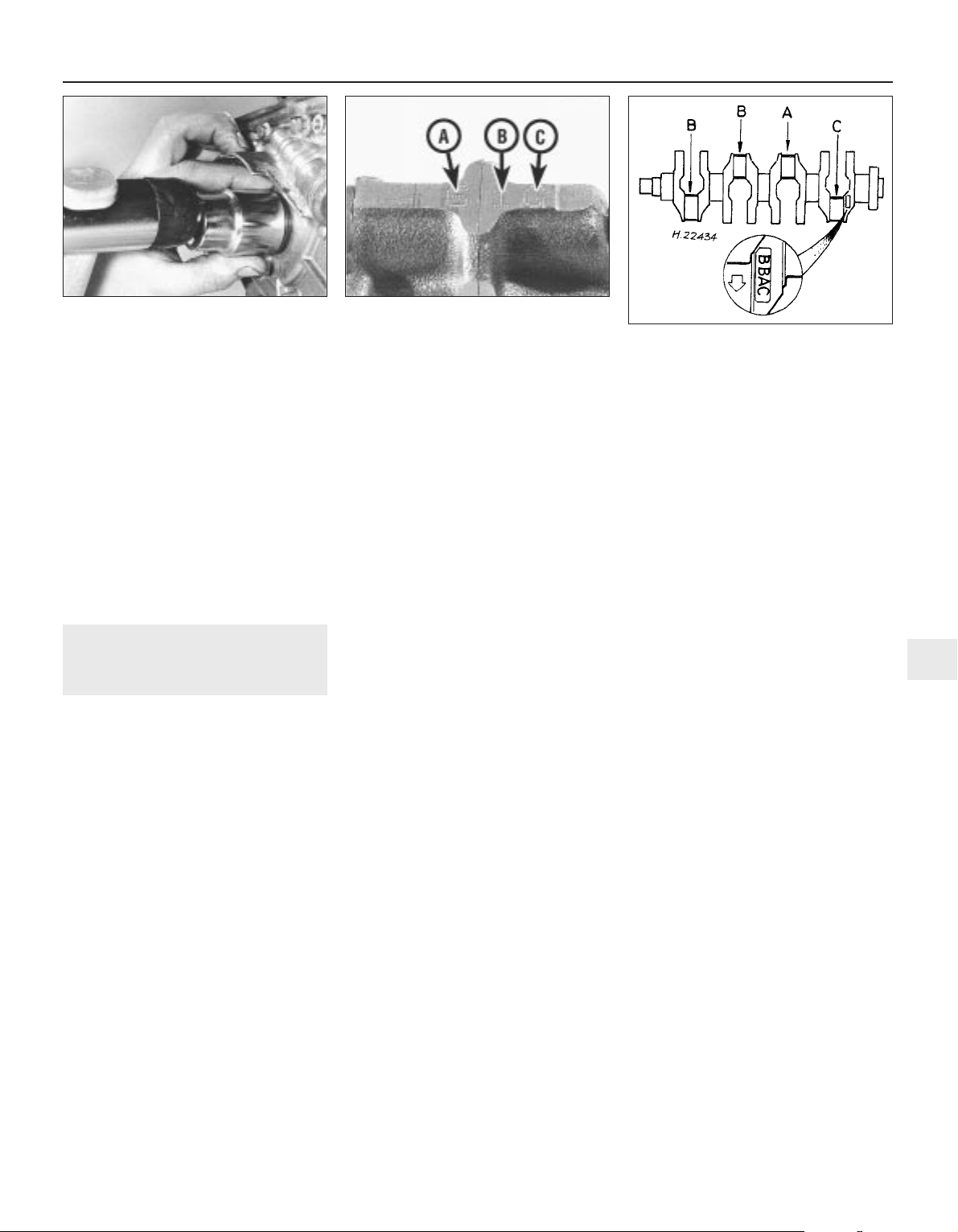
33 Refit the dipstick tube to the cylinder
block/crankcase, tightening the bolts to the
specified torque wrench setting.
34 Refit the timing belt inner cover, the
sprocket(s) and tensioner, and the belt itself.
35 Using a torque wrench, check that the
amount of force required to rotate the
crankshaft does not exceed 31 Nm. If the
effort required is greater than this, the engine
must be dismantled again to trace and rectify
the cause. This value takes into account the
increased friction of a new engine and is
much higher than the actual pressure required
to rotate a run-in engine, so do not make
allowances for tight components.
19 Piston/connecting rod
assembly - refitting and big-end
bearing running clearance check
4
Selection of bearing shells
1 The big-end bearing running clearance is
controlled in production by selecting one of
three grades of bearing shell. The grades are
indicated by a colour-coding marked on the
edge of each shell which governs the shell’s
thickness, as follows:
a) Yellow - Thin.
b) Blue - Intermediate.
c) Red - Thick.
2 If shells of differing grades are to be fitted
to the same journal, the thicker shell must
always be fitted to the big-end bearing cap
location.
3 If the bearing shells are to be renewed, first
check and record the codes stamped on the
front face of each big-end bearing cap and
connecting rod. The number stamped on the
big-end bearing cap is the bearing size code,
the number stamped on the connecting rod
is the piston/rod assembly’s cylinder number
and the letter stamped on the connecting rod
is the weight code (see illustration).
4 Secondly, check and record the
crankpin/big-end journal code letters
stamped on the crankshaft’s left-hand web
(see illustration), No 1 journal’s code letter
being the first. If the original crankshaft is to
be re-used, the code letter can be checked by
direct measurement.
5 If the crankshaft is found to be excessively
worn, then it must be renewed and the code
letters of the new component must be used
instead to select a new set of bearing shells.
6 Matching the codes noted to the following
table, select a new set of bearing shells:
Cap code Crankshaft
number code letter Shells
5 A Blue, Blue
5 B Red, Blue
5 C Red, Red
6 A Blue, Yellow
6 B Blue, Blue
6 C Red, Blue
7 A Yellow, Yellow
7 B Blue, Yellow
7 C Blue, Blue
Big-end bearing running
clearance check
7 The big-end bearing running clearance
should be checked if there is any doubt about
the amount of crankshaft wear that has taken
place, if the crankshaft has been reground
and is to be refitted with non-Rover
undersized bearing shells, or if non-genuine
bearing shells are to be fitted. If the original
crankshaft or a Rover replacement part is to
be installed, the shell selection procedure
given above will produce the correct
clearances and a further check will not be
necessary. If the clearance is to be checked, it
can be done in either of two ways.
8 The first method is to refit the big-end
bearing cap to the connecting rod, with
bearing shells in place. With the cap retaining
bolts tightened to the specified torque, use an
internal micrometer or vernier caliper to
measure the internal diameter of each
assembled pair of bearing shells. If the
diameter of each corresponding crankshaft
journal is measured and then subtracted from
the bearing internal diameter, the result will be
the big-end bearing running clearance.
9 The second method is to use Plastigauge.
Place a strand of Plastigauge on each
(cleaned) crankpin journal and refit the (clean)
piston/connecting rod assemblies, shells and
big-end bearing caps, tightening the bolts to
the specified torque wrench settings. Take
care not to disturb the Plastigauge. Dismantle
the assemblies without rotating the crankshaft
and use the scale printed on the Plastigauge
envelope to obtain the big-end bearing
running clearance. On completion of the
measurement, carefully scrape off all traces of
Plastigauge from the journal and shells using
a fingernail or other object which will not
score the components.
Final piston/connecting rod
assembly refitting
10 Note that the following procedure
assumes that the cylinder liners have been
refitted to the cylinder block/crankcase and
that the crankshaft and main bearing ladder
are in place. It is of course possible to refit the
piston/connecting rod assemblies to the
cylinder bores, to refit the crankshaft and to
reassemble the piston/connecting rods on the
crankshaft before refitting the main bearing
ladder (see Section 18).
11 Clean the backs of the bearing shells and
the bearing recesses in both the connecting
rod and the big-end bearing cap. If new shells
are being fitted, ensure that all traces of the
protective grease are cleaned off using
paraffin. Wipe dry the shells and connecting
rods with a lint-free cloth.
12 Press the bearing shells into their
locations, ensuring that the tab on each shell
engages in the notch in the connecting rod or
big-end bearing cap and taking care not to
touch any shell’s bearing surface with your
fingers. Note the following points:
a) If bearing shells of differing grades are to
be fitted to the same journal, the
thicker shell must always be fitted to the
big-end bearing cap location (see
paragraph 1).
b) On all engines, if the original big-end
bearing shells are being re-used, these
must be refitted to their original locations
in the connecting rod and big-end bearing
cap.
Engine removal and general overhaul procedures 2B•15
19.4 Crankpin (big-end) journal size code
location
19.3 Big-end bearing size code number (A
- on cap) piston/connecting rod assembly
cylinder number (B) and connecting rod
weight code letter (C)
18.31b Fitting a new crankshaft right-hand
oil seal
2B
1689 Rover 214 & 414 Updated Version 09/97

13 Lubricate the cylinder bores, the pistons
and piston rings, then lay out each
piston/connecting rod assembly in its
respective position.
14 Starting with assembly No 1, make sure
that the piston rings are still correctly spaced,
then clamp them in position with a piston ring
compressor.
15 Insert the piston/connecting rod assembly
into the top of liner No 1, ensuring that the
arrow (or FRONT marking) on the piston
crown faces the timing belt end of the engine.
Note that the stamped marks on the
connecting rod and big-end bearing cap
should face the front (alternator bracket side)
of the engine. Using a block of wood or
hammer handle against the piston crown, tap
the assembly into the liner until the piston
crown is flush with the top of the liner (see
illustrations).
16 Ensure that the bearing shell is still
correctly installed. Taking care not to mark the
liner bores, liberally lubricate the crankpin and
both bearing shells, then pull the
piston/connecting rod assembly down the
bore and onto the crankpin. Noting that the
faces with the stamped marks must match
(which means that the bearing shell locating
tabs abut each other), refit the big-end
bearing cap, tightening the bolts finger-tight
at first.
17 Use a torque wrench to tighten the bolts
evenly to the (first stage) torque wrench
setting specified, then use an angular torque
gauge to tighten the bolts evenly through the
(second stage) angle specified (see
illustrations).
18 Repeat the procedure for the remaining
three piston/connecting rod assemblies, but
do not attempt to rotate the crankshaft.
19 Thoroughly degrease the mating surfaces
of the oil rail and the main bearing ladder.
Apply the special Rover sealant to the oil rail
mating surface (see illustration 18.27).
Carefully follow the instructions supplied with
the sealant kit.
20 Refit the oil rail, tightening the nuts to the
specified torque wrench setting.
21 Refit the oil pump pick-up/strainer pipe
and sump.
22 Refit the cylinder head. Rotate the
crankshaft to the 90° BTDC position so that
the crankshaft sprocket timing marks align.
23 Refit the dipstick tube to the cylinder
block/crankcase, tightening the bolts to the
specified torque wrench setting.
24 Refit the hydraulic tappets and
camshaft(s).
25 Refit the timing belt inner cover,
sprocket(s) and tensioner, and the belt itself.
26 Using a torque wrench, check that the
amount of force required to rotate the crankshaft
does not exceed 31 Nm. If the effort required is
greater than this, the engine must be dismantled
again to trace and rectify the cause. This value
takes into account the increased friction of a
new engine and is much higher than the actual
pressure required to rotate a run-in engine, so
do not make allowances for tight components.
2B•16 Engine removal and general overhaul procedures
19.17b . . . then use angular torque gauge to tighten bolts through
angle specified (second stage)
19.17a Tighten connecting rod big-end bearing cap bolts to
specified torque wrench setting (first stage) . . .
18.15b Using piston ring compressor to clamp piston rings19.15a Arrow or FRONT marking (arrowed) on piston crown must
point to timing belt end of engine
1689 Rover 214 & 414 Updated Version 09/97

20 Engine - initial start-up
after overhaul
2
1 With the engine refitted in the vehicle,
double-check the engine oil and coolant
levels. Make a final check that everything has
been reconnected and that there are no tools
or rags left in the engine compartment.
2 With the spark plugs removed and the
ignition system disabled by earthing the ignition
HT coil distributor spark plug (HT) lead with a
jumper lead, turn the engine over on the starter
until the oil pressure warning lamp goes out.
3 Refit the spark plugs and connect all the
spark plug (HT) leads.
4 Start the engine, noting that this may take a
little longer than usual due to the fuel system
components being empty.
5 While the engine is idling, check for fuel,
coolant and oil leaks. Do not be alarmed if
there are some odd smells and smoke from
parts getting hot and burning off oil deposits.
If the hydraulic tappets have been disturbed,
some valve gear noise may be heard at first;
this should disappear as the oil circulates fully
around the engine and normal pressure is
restored in the tappets.
6 Keep the engine idling until hot coolant is
felt circulating through the top hose, check
the ignition timing and idle speed and mixture
(as appropriate), then switch it off.
7 After a few minutes, recheck the oil and
coolant levels and top up as necessary.
8 If they were tightened as described, there is
no need to re-tighten the cylinder head bolts
once the engine has first run after reassembly.
9 If new pistons, rings or crankshaft bearings
have been fitted, the engine must be run-in for
the first 500 miles (800 km). Do not operate
the engine at full throttle or allow it to labour in
any gear during this period. It is
recommended that the oil and filter be
changed at the end of this period.
Engine removal and general overhaul procedures 2B•17
2B
1689 Rover 214 & 414 Updated Version 09/97

3
1689 Rover 214 & 414 Updated Version 09/97
Chapter 3
Cooling, heating and ventilation systems
Air conditioning compressor drivebelt - inspection, adjustment
and renewal . . . . . . . . . . . . . . . . . . . . . . . . . . . . . . . . . . . . . . . . . . 13
Air conditioning refrigerant - level check . . . . . . . . . . . . . . . . . . . . . . 14
Air conditioning system components - removal and refitting . . . . . . 15
Coolant pump - removal and refitting . . . . . . . . . . . . . . . . . . . . . . . . 7
Cooling system - draining, flushing and filling . . . . . . . . . . . . . . . . . 2
Cooling system - general inspection . . . . . . . . . . . . . . . . . . . . . . . . . 3
Cooling system electrical switches - testing, removal and refitting . 9
Cooling system hoses - renewal . . . . . . . . . . . . . . . . . . . . . . . . . . . . 4
Electric cooling fan - testing, removal and refitting . . . . . . . . . . . . . . 8
General information and precautions . . . . . . . . . . . . . . . . . . . . . . . . 1
Heater components - removal and refitting . . . . . . . . . . . . . . . . . . . 10
Heater controls - removal, refitting and adjustment . . . . . . . . . . . . . 12
Heater ducts and vents - removal and refitting . . . . . . . . . . . . . . . . . 11
Radiator and expansion tank - removal, inspection and refitting . . . 5
Thermostat - removal, testing and refitting . . . . . . . . . . . . . . . . . . . . 6
3•1
Contents
Specifications
System
Type . . . . . . . . . . . . . . . . . . . . . . . . . . . . . . . . . . . . . . . . . . . . . . . . . . . . Pressurised, pump-assisted thermo-syphon with front mounted
radiator and thermostatically-controlled electric cooling fan
Thermostat
Type . . . . . . . . . . . . . . . . . . . . . . . . . . . . . . . . . . . . . . . . . . . . . . . . . . . . Wax
Start to open temperature . . . . . . . . . . . . . . . . . . . . . . . . . . . . . . . . . . . 76 to 80°C
Fully open temperature . . . . . . . . . . . . . . . . . . . . . . . . . . . . . . . . . . . . . . 82 or 88°C (actual value stamped in unit end)
Full lift height . . . . . . . . . . . . . . . . . . . . . . . . . . . . . . . . . . . . . . . . . . . . . 9.0 mm
Expansion tank
Cap pressure . . . . . . . . . . . . . . . . . . . . . . . . . . . . . . . . . . . . . . . . . . . . . 0.9 to 1.0 bar
Cooling fan
Operating temperature . . . . . . . . . . . . . . . . . . . . . . . . . . . . . . . . . . . . . . 88 to 92°C
Torque wrench settings Nm lbf ft
Cooling system
Fan motor nuts . . . . . . . . . . . . . . . . . . . . . . . . . . . . . . . . . . . . . . . . . . . . 5 4
Temperature gauge sender unit . . . . . . . . . . . . . . . . . . . . . . . . . . . . . . . 15 11
Thermostat housing cover bolts . . . . . . . . . . . . . . . . . . . . . . . . . . . . . . . 9 7
Thermostat housing/dipstick tube-to-cylinder block/crankcase bolt . . . 9 7
Coolant rail-to-cylinder block/crankcase bolts . . . . . . . . . . . . . . . . . . . . 9 7
Coolant pump-to-timing belt upper left-hand (inner) cover bolt . . . . . . 9 7
Coolant pump-to-cylinder block/crankcase bolts . . . . . . . . . . . . . . . . . 10 7
Heating system
Heater lower mounting nut . . . . . . . . . . . . . . . . . . . . . . . . . . . . . . . . . . . 21 15
Heater blower motor mounting bolts . . . . . . . . . . . . . . . . . . . . . . . . . . . 10 7
Air conditioning system
Compressor mounting bolts . . . . . . . . . . . . . . . . . . . . . . . . . . . . . . . . . . 45 33
Condenser unions . . . . . . . . . . . . . . . . . . . . . . . . . . . . . . . . . . . . . . . . . . 17 13
Evaporator inlet union (from receiver drier) . . . . . . . . . . . . . . . . . . . . . . 17 13
Evaporator outlet union . . . . . . . . . . . . . . . . . . . . . . . . . . . . . . . . . . . . . 33 24
Receiver drier union . . . . . . . . . . . . . . . . . . . . . . . . . . . . . . . . . . . . . . . . 17 13
Trinary switch . . . . . . . . . . . . . . . . . . . . . . . . . . . . . . . . . . . . . . . . . . . . . 12 9
Easy, suitable for
novice with little
experience
Fairly easy, suitable
for beginner with
some experience
Fairly difficult,
suitable for competent
DIY mechanic
Difficult, suitable for
experienced DIY
mechanic
Very difficult,
suitable for expert DIY
or professional
Degrees of difficulty
5
4
3
2
1

1 General information and
precautions
General information
The cooling system is of the pressurised,
pump-assisted thermo-syphon type. It
consists of the front-mounted radiator, a
translucent expansion tank mounted on the
right-hand inner wing, a thermostaticallycontrolled electric cooling fan mounted on the
rear of the radiator, a thermostat and a
centrifugal coolant pump, as well as the
connecting hoses (see illustration). The
coolant pump is driven by the engine timing
belt.
The system is of the by-pass type, allowing
coolant to circulate around the engine while
the thermostat is closed. With the engine
cold, the thermostat closes off the coolant
feed from the bottom radiator hose. Coolant is
then drawn into the engine via the heater
matrix, inlet manifold and from the top of the
cylinder block. This allows some heat transfer,
by convection, to the radiator through the top
hose whilst retaining the majority of heat
within the cylinder block.
The siting of the thermostat in the intake
rather than the outlet side of the system
ensures that the engine warms up quickly by
circulating a small amount of coolant around a
shorter tract. This also prevents temperature
build-up in the cylinder head prior to the
thermostat opening.
When the coolant reaches a predetermined
temperature, the thermostat opens and the
coolant is allowed to flow freely through the
top hose to the radiator. As the coolant
circulates through the radiator, it is cooled by
the inrush of air when the vehicle is in forward
motion. Airflow is supplemented by the action
of the electric cooling fan when necessary.
Upon reaching the bottom of the radiator, the
coolant is now cooled and the cycle is
repeated.
With the engine at normal operating
temperature, the coolant expands and some
of it is displaced into the expansion tank. This
coolant collects in the tank and is returned to
the radiator when the system cools.
The electric cooling fan mounted behind
the radiator is controlled by a thermostatic
switch located in the radiator side tank.
At a predetermined coolant temperature
the switch contacts close, thus actuating the
fan.
Precautions
Cooling system
Do not attempt to remove the expansion
tank filler cap or to disturb any part of the
cooling system whilst it or the engine is hot,
as there is a very great risk of scalding. If the
expansion tank filler cap must be removed
before the engine and radiator have fully
cooled down (even though this is not
recommended) the pressure in the cooling
system must first be released. Cover the cap
with a thick layer of cloth, to avoid scalding,
and slowly unscrew the filler cap until a
hissing sound can be heard. When the hissing
has stopped, showing that pressure is
released, slowly unscrew the filler cap until
it can be removed. If more hissing sounds
are heard, wait until they have stopped
before unscrewing the cap completely. At
all times keep well away from the filler
opening.
Do not allow antifreeze to come in contact
with your skin or painted surfaces of the
vehicle. Rinse off spills immediately with
plenty of water. Never leave antifreeze lying
around, it is fatal if ingested.
If the engine is hot, the electric cooling fan
may start rotating even if the engine is not
running, so be careful to keep hands, hair and
loose clothing well clear when working in the
engine compartment.
Air conditioning system
On models equipped with an air
conditioning system, it is necessary to
observe special precautions whenever dealing
with any part of the system, its associated
components and any items which necessitate
disconnection of the system. If for any reason
the system must be disconnected, entrust this
task to your Rover dealer or a refrigeration
engineer.
Refrigerant must not be allowed to come in
contact with a naked flame, otherwise a
poisonous gas will be created. Do not allow
the fluid to come in contact with the skin or
eyes.
2 Cooling system - draining,
flushing and refilling
Refer to Chapter 1.
3 Cooling system -
general inspection
Refer to “Weekly Checks” and Chapter 1.
3•2 Cooling, heating and ventilation systems
1.0 Cooling system components
1 Radiator
2 Cooling fan and cowling
3 Radiator mounting
rubbers
4 Bottom hose
5 Top hose
6 Coolant pipe - bottom
hose to thermostat
housing
7 Thermostat housing
cover
8 Gasket
9 Thermostat
10 Thermostat housing
11 O-ring
12 Coolant pump
13 Expansion tank
14 Hose - heater matrix and
manifold return
15 Hose - heater matrix and
manifold feed
16 Heater temperature
control valve
17 Coolant filler stem
18 Cooling system bleed
screw
19 Engine overheat switch -
where fitted
20 Coolant pipe - expansion
tank to bottom hose
21 Hose - expansion tank
return
22 Sealing ring
23 Cooling fan thermostatic
switch
24 Locking ring
1689 Rover 214 & 414 Updated Version 09/97

4 Cooling system hoses -
renewal
2
1 If inspection of the cooling system reveals a
faulty hose, then it must be renewed as
follows.
2 First drain the cooling system. If the coolant
is not due for renewal, it may be re-used if
collected in a clean container.
3 To disconnect any hose, use a screwdriver
to slacken the clips then move them along the
hose clear of the outlet. Carefully work the
hose off its outlets. Do not attempt to
disconnect any part of the system when still
hot.
4 Note that the radiator hose outlets are
fragile. Do not use excessive force when
attempting to remove the hoses. If a hose
proves stubborn, try to release it by rotating it
on its outlets before attempting to work it off.
If all else fails, cut the hose with a sharp knife
then slit it so that it can be peeled off in two
pieces. While expensive, this is preferable to
buying a new radiator.
5 When refitting a hose, first slide the clips
onto the hose then work the hose onto its
outlets. If the hose is stiff, use soap as a
lubricant or soften it by first soaking it in
boiling water whilst taking care to prevent
scalding.
6 Work each hose end fully onto its outlet,
check that the hose is settled correctly and is
properly routed, then slide each clip along the
hose until it is behind the outlet flared end
before tightening it securely.
7 Refill the system with coolant.
8 Check carefully for leaks as soon as
possible after disturbing any part of the
cooling system.
5 Radiator and expansion tank
- removal, inspection and
refitting
2
Removal
Radiator
1 Drain the cooling system.
2 On models equipped with air conditioning,
remove the condenser fan, then undo the two
bolts securing the air conditioning pipes to the
bonnet platform.
3 Remove the air cleaner metal intake duct
and intake hose.
4 Disconnect the radiator cooling fan wiring
connector, then slacken and remove the bolt
securing the earth leads to the bonnet platform.
Disconnect the wiring from the thermostatic
switch(es) which are fitted to the right-hand
side of the radiator (see illustrations).
5 Slacken the bottom hose retaining clip and
disconnect the hose from the radiator.
6 Slacken the retaining clips and disconnect
the top hose from both the radiator and
engine coolant elbow (see illustrations).
Position the hose clear of the radiator so that
it does not hinder removal.
7 Undo the two bolts securing the upper
mounting brackets to the bonnet platform and
remove the brackets from the radiator.
Disengage the radiator from its lower mounting
points and carefully manoeuvre it out of the
engine compartment (see illustrations).
Cooling, heating and ventilation systems 3•3
5.6a Slacken clips and disconnect top
hose from radiator . . .
5.4b Disconnecting wiring connector from
radiator switch
5.7a Undo radiator mounting bolts . . .
5.6b . . . and engine coolant elbow
5.7c . . . and manoeuvre radiator out of
engine compartment
5.7b . . . remove mounting brackets . . .
5.4a Disconnect cooling fan wiring
connector then remove earth lead
retaining bolt (arrowed)
3
1689 Rover 214 & 414 Updated Version 09/97
Never work on the cooling
system when it is hot.
Release any pressure from
the system by loosening the
expansion tank cap, having first
covered it with a cloth to avoid any
possibility of scalding.
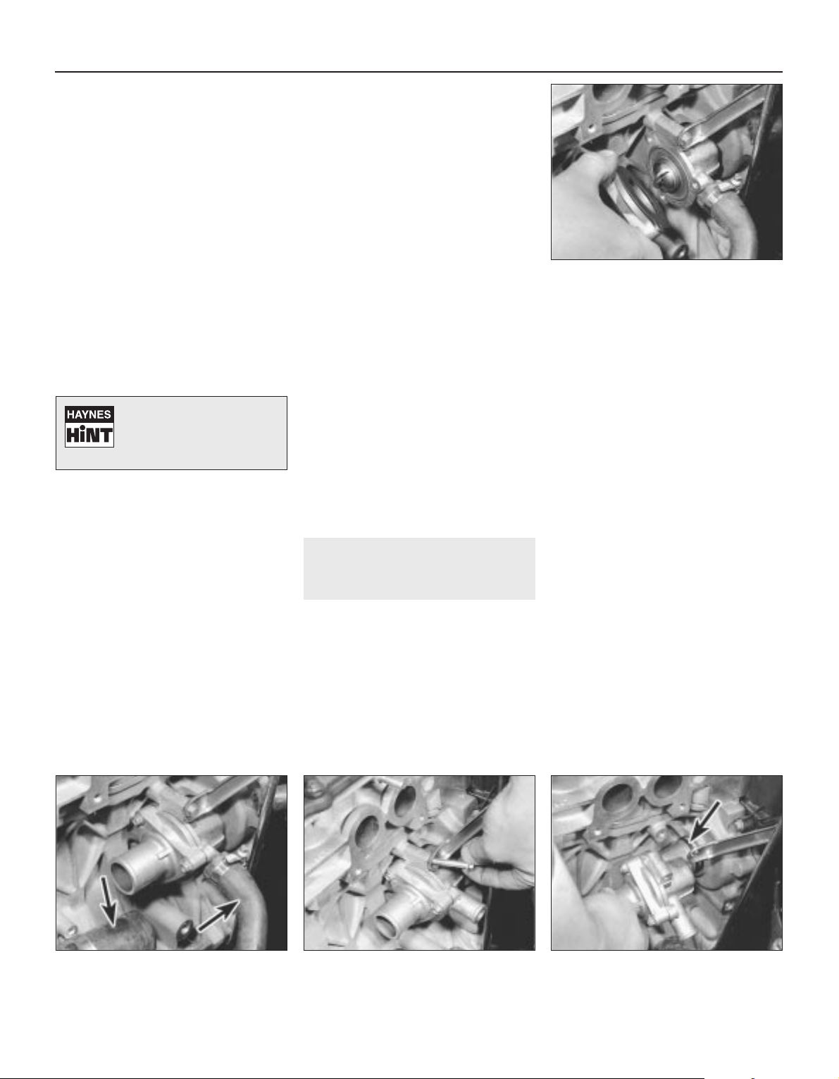
Expansion tank
8 Slacken and remove the three bolts
securing the expansion tank to the body.
Unscrew the expansion tank cap and tip out
its contents into a suitable container.
9 Slacken the retaining clips then disconnect
both the hoses from the expansion tank and
remove the tank from the vehicle.
Inspection
Radiator
10 If the radiator was removed because of
clogging (causing overheating) then try
reverse flushing or, in severe cases, use a
radiator cleanser strictly in accordance with
the manufacturer’s instructions. Ensure
that the cleanser is suitable for use in a
copper/brass radiator. Refer to Chapter 1 for
further information
11 Use a soft brush and an air line or garden
hose to clear the radiator matrix of leaves,
insects etc.
12 Major leaks or extensive damage should
be repaired by a specialist, or the radiator
should be renewed or exchanged for a
reconditioned unit.
13 Examine the mounting rubbers for signs
of damage or deterioration and renew if
necessary.
Expansion tank
14 Empty any remaining coolant from the
tank and flush it with fresh water to clean it. If
the tank is leaking it must be renewed but it is
worth first attempting a repair using a
proprietary sealant or suitable adhesive.
15 The expansion tank cap should be
cleaned and checked whenever it is removed.
Check that its sealing surfaces and threads
are clean and undamaged and that they mate
correctly with those of the expansion tank.
16 The cap’s performance can only be
checked by using a cap pressure-tester
(cooling system tester) with a suitable
adaptor. On applying pressure, the cap’s
pressure relief valve should hold until the
specified pressure is reached, at which point
the valve should open.
17 If there is any doubt about the cap’s
performance, then it must be renewed. Ensure
that the replacement is of the correct type and
rating.
Refitting
Radiator
18 Refitting is the reverse of the removal
procedure whilst noting the following:
a) Ensure that the radiator is seated
correctly and without strain on its
mountings.
b) Ensure that the radiator hoses are
securely held by the retaining clips.
c) Ensure that all wiring connectors are
correctly routed so that they are clear of
the cooling fan and are retained by any
necessary clips or ties.
d) Refill the cooling system as described in
Chapter 1.
Expansion tank
19 Refitting is the reverse of the removal
procedure whilst noting the following:
a) Ensure that all hoses are correctly routed
with no kinks or sharp bends and are
securely held by the retaining clips.
b) Top up the expansion tank as described
in Chapter 1.
6 Thermostat -
removal, testing and refitting
3
Removal
1 Note that access to the thermostat is very
limited. Depending on the tools available, it
may be easier to raise the front of the vehicle
and to work from underneath, ensuring that
the vehicle is securely supported on axle
stands. In most cases, access is better if the
air cleaner and carburettor (or throttle body on
SPi engines) are removed and is best if the
complete inlet manifold is removed. If the inlet
manifold is removed, the thermostat housing
cover can be unbolted to remove the
thermostat without disturbing the housing
itself (see illustration). Whichever method is
used, first drain the cooling system.
2 On carburettor models equipped with a
catalytic converter, either remove the
thermostatically-operated vacuum switch or
disconnect the vacuum pipes from the switch
so that it can be removed with the thermostat
housing.
3 Unbolt the coolant rail from the rear of the
cylinder block/crankcase, then slacken the
clips and disconnect the coolant rail hose and
heater/inlet manifold return hose from the
thermostat housing (see illustration).
4 Undo the thermostat housing/dipstick tubeto-cylinder block/crankcase bolt and remove
the thermostat housing from the cylinder
block/crankcase. Remove the housing O-ring
which must be renewed whenever it is
disturbed (see illustrations).
5 Slacken and remove the three thermostat
housing cover bolts and lift off the housing
cover. Discard the gasket and remove the
thermostat.
Testing
6 If the thermostat remains in the open
position at room temperature, then it is faulty
and must be renewed.
7 To test it fully, suspend the (closed)
thermostat on a length of string in a container
of cold water, with a thermometer beside it.
3•4 Cooling, heating and ventilation systems
6.4b . . . and withdraw thermostat housing
(O-ring arrowed) – inlet manifold removed
for clarity
6.4a . . . unscrew dipstick tube retaining
bolt . . .
6.3 Disconnect coolant rail and
heater/inlet manifold hoses (arrowed) . . .
6.1 Thermostat can be removed without
disturbing housing if inlet manifold is first
removed
1689 Rover 214 & 414 Updated Version 09/97
Minor leaks from the
radiator can be cured using
a suitable sealant with the
radiator in situ.
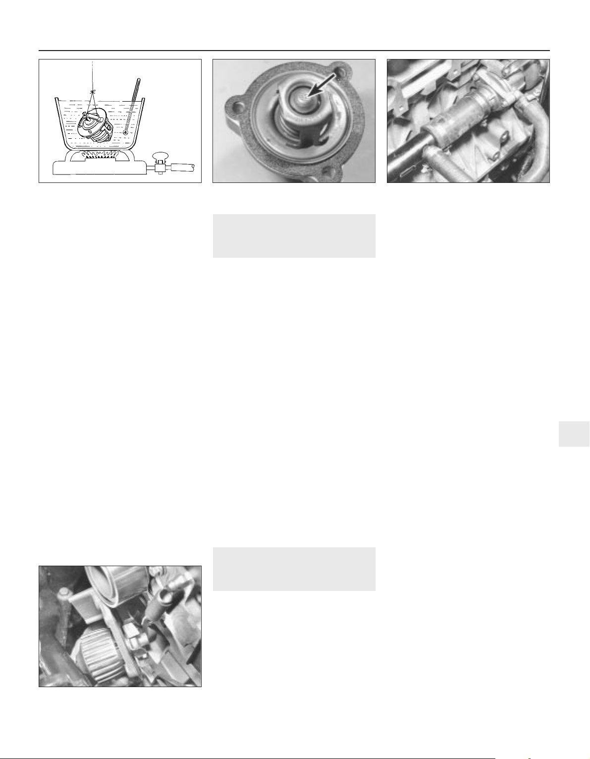
Ensure that neither touches the side of the
container (see illustration).
8 Heat the water and check the temperature
at which the thermostat begins to open.
Compare this value with that specified.
Continue to heat the water until the
thermostat is fully open. The temperature at
which this should happen is stamped in the
unit’s end (see illustration). Remove the
thermostat and measure the height of the fully
opened valve, then allow the thermostat to
cool down and check that it closes fully.
9 If the thermostat does not open and close
as described, if it sticks in either position, or if
it does not open at the specified temperature,
then it must be renewed.
Refitting
10 Refitting is the reverse of the removal
procedure, noting the following (see
illustration):
a) Clean the thermostat housing, housing
cover and cylinder block/crankcase
mating surfaces thoroughly.
b) Always fit a new housing cover gasket
and O-ring. Smear the O-ring with grease
to aid refitting.
c) Tighten all bolts to their specified torque
wrench settings (where given).
d) Ensure the coolant hose clips are
positioned so that they do not foul any
other component, then tighten them
securely.
e) Refit any components removed for
improved access.
f) Refill the cooling system as described in
Chapter 1.
7 Coolant pump -
removal and refitting
4
Removal
1 Coolant pump failure is usually indicated by
coolant leaking from the gland behind the
pump bearing, or by rough and noisy
operation, usually accompanied by excessive
pump spindle play. If the pump shows any of
these symptoms then it must be renewed as
follows.
2 Drain the cooling system.
3 Remove the timing belt.
4 Noting the location of the pillar bolt(s),
unscrew the five bolts securing the coolant
pump to the cylinder block/crankcase, then
unscrew the single bolt securing the pump to
the timing belt upper left-hand (inner) cover.
5 Withdraw the coolant pump and discard its
sealing ring which should be renewed
whenever it is disturbed. Carefully clean the
cylinder block/crankcase mating surface and
the pump socket (see illustration).
Refitting
6 On refitting, install the pump using a new
sealing ring and tighten all bolts to the
specified torque wrench settings.
7 The remainder of the refitting procedure is
the reverse of removal.
8 Electric cooling fan -
testing, removal and refitting
2
Note: On models equipped with air
conditioning, there are two switches fitted to
the right-hand side of the radiator, the lower of
these is the cooling fan switch.
Testing
1 The cooling fan motor is supplied with
current via the ignition switch, fuse 4 and the
cooling fan relay. The relay is energised by the
radiator-mounted thermostatic switch which
is fed via fuse number 15.
2 If the fan does not appear to work, first
check that both fuses are in good condition
and have not blown. Run the engine until
normal operating temperature is reached,
then allow it to idle. If the fan does not cut in
within a few minutes, switch off the ignition
and disconnect the two wires from the
thermostatic switch. Bridge these two wires
with a length of spare wire and switch on the
ignition. If the fan now operates, the
thermostatic switch is probably faulty and
must be tested further as described in
Section 9.
3 If the fan still fails to operate, check that full
battery voltage is available at the switch’s
light green and grey wire terminal. If not,
check the feed for a blown fuse or other fault
such as a broken wire. If the feed is good,
check the cooling fan relay, see Chapter 12. If
the relay operates correctly, check for
continuity between the fan motor black wire
terminal and a good earth point on the body. If
not, then the earth connection is faulty and
must be remade. The circuit earth connection
is one of those at earth header 1, attached to
the left-hand inner wing panel next to the
battery.
4 If the switch and wiring are in good
condition, the fault must be in the motor itself.
This can be checked by disconnecting it from
the wiring loom and connecting a 12 volt
supply directly to it. If the motor does not
work then it must be renewed.
Removal
5 Drain the cooling system, then jack up the
front of the vehicle and support it securely on
axle stands.
6 From underneath the front of the vehicle,
slacken and remove the three bolts securing
the bumper flange to the body. Remove the
seven bolts securing the front undercover
panel to the body and remove the panel.
7 Remove the air cleaner metal intake duct
and intake hose.
8 Slacken the retaining clips and disconnect
the top hose from both the radiator and
engine. Position the hose clear of the radiator
so that it does not hinder removal.
9 Disconnect the radiator cooling fan wiring
connector.
Cooling, heating and ventilation systems 3•5
6.10 Thermostat housing and coolant
hoses refitted
6.8 Note temperature specification
stamped on thermostat end
6.7 Testing the thermostat
7.5 Removing the coolant pump
3
1689 Rover 214 & 414 Updated Version 09/97

10 Undo the four nuts securing the cooling
fan cowling to the rear of the radiator and
manoeuvre the fan assembly out of the engine
compartment (see illustrations).
11 To dismantle the assembly, first prise off
the fan retaining circlip, then lift the fan off the
motor spindle. Undo the three nuts which
secure the motor assembly to the cowling
then release the motor wiring and connector
and separate the motor and cowling (see
illustration).
Refitting
12 Refitting is a reverse of the removal
procedure, noting the following:
a) If necessary, reassemble the fan motor,
cowling and fan, then tighten the motor
retaining nuts to the specified torque.
Ensure that the motor wiring is securely
retained by the cowling clips.
b) Ensure that the radiator hose is securely
held by its retaining clips.
c) On completion, refill the cooling system
as described in Chapter 1.
9 Cooling system electrical
switches - testing, removal
and refitting
2
Note: On models equipped with air
conditioning, there are two switches fitted to
the right-hand side of the radiator, the lower of
these is the cooling fan switch.
Testing
Cooling fan thermostatic switch
1 Refer to Section 8 for details of a quick test
which should eliminate most faulty switches.
If the switch is to be renewed, or to be tested
thoroughly, it must be removed.
2 To carry out a thorough test of the switch,
use two spare wires to connect to it either a
multimeter (set to the resistance function) or a
battery and bulb test circuit. Suspend the
switch in a pan of water which is being
heated. Measure the temperature of the water
with a thermometer. Do not let either the
switch or the thermometer touch the pan itself
(see illustration).
3 The switch contacts should close to the ON
position (ie: continuity should exist) when the
water reaches the temperature specified.
Stop heating the water and allow it to cool
down. The switch contacts should open.
4 If the switch’s performance is significantly
different from that specified, or if it does not
work at all, then it must be renewed.
Coolant temperature gauge sender
unit
5 The coolant temperature gauge mounted in
the instrument panel is fed with a stabilised 10
volt supply from the instrument panel feed (via
the ignition switch and fuse 1), its earth being
controlled by the sender unit.
6 The sender unit is screwed into the coolant
outlet elbow mounted on the left-hand end of
the cylinder head, underneath the distributor
(see illustration). It contains a thermistor,
which is an element whose electrical
resistance decreases at a predetermined rate
as its temperature rises. Thus, when the
coolant is cold, the sender’s resistance is
high, current flow through the gauge is
reduced and the gauge needle points to the
C (cold) end of the scale. If the unit is faulty it
must be renewed.
7 If the gauge develops a fault, check first the
other instruments. If they do not work at all,
check the instrument panel feed. If the
readings are erratic, there may be a fault in the
voltage stabiliser which will necessitate the
renewal of the gauge unit or printed circuit. If
the fault is in the temperature gauge alone,
check it as follows.
8 If the gauge needle remains at the C end of
the scale, disconnect the sender unit wire and
earth it to the cylinder head. If the needle then
deflects when the ignition is switched on, then
the sender unit is proven faulty and must be
renewed. If the needle still does not move,
remove the instrument panel and check the
continuity of the green/blue wire between the
gauge and the sender unit and the feed to
the gauge unit. If continuity is shown and the
fault still exists, then the gauge is faulty and
the gauge unit must be renewed.
9 If the gauge needle remains at the H end of
the scale, disconnect the sender unit wire. If
the needle then returns to the C end of the
scale when the ignition is switched on, then
the sender unit is proven faulty and must be
renewed. If the needle still does not move,
check the remainder of the circuit as
described above.
Inlet manifold pre-heater temperature
switch - carburettor engines
10 The switch screwed into the underside of
the inlet manifold on carburettor engines
3•6 Cooling, heating and ventilation systems
9.6 Coolant temperature gauge sender
unit
9.2 Testing cooling system electrical
switch
8.11 Cooling fan motor retaining nuts
(arrowed)
8.10b . . . and remove fan assembly8.10a Undo cooling fan cowling retaining
nuts (2 arrowed) . . .
1689 Rover 214 & 414 Updated Version 09/97

controls the inlet manifold heater circuit (see
illustration).
11 The switch contacts should be closed to
the ON position (ie: continuity should exist)
only at temperatures below 50°C. Remove the
switch and test it as described in paragraphs 2 to 4.
Thermostatically-operated vacuum
switch - carburettor engines equipped
with catalytic converters
12 This switch is screwed into the thermostat
housing.
13 To test the switch, fit two suitable lengths
of hose to the switch and suspend the switch
in a pan of water which is being heated.
Measure the temperature of the water
with a thermometer. Do not let either the
switch or the thermometer touch the pan
itself.
14 Blow down one of the hoses attached to
the switch. The switch should be closed (ie:
passes no air) when the water temperature is
below 70°C. Above 70°C, the switch should
open and air should flow freely through the
hoses. Stop heating the water then allow the
water to cool down and check that the switch
closes at 70°C or just below.
15 If the switch performance is significantly
different from that specified, or if it does not
work at all, then it must be renewed.
Coolant temperature sensor - fuel
injected engines
16 This sensor, which is screwed into the
underside of the inlet manifold (SPi engines),
or located in the coolant pipe adjacent to the
foward top edge of the timing belt cover (MPi
engines), is a thermistor (see paragraph 6)
which is supplied with approximately 5 volts
by the engine management system ECU. The
ECU also controls the sensor’s earth path
and, by measuring the amount of current in
the sensor circuit, determines the engine’s
temperature. This information is used, in
conjunction with other inputs, to control idle
speed, injector opening time duration and
ignition timing.
17 If the sensor circuit should fail to provide
adequate information, the ECU’s back-up
facility assumes a value corresponding to
60°C. The sensor itself can be tested only by
having a Rover dealer check the complete
system using the correct diagnostic
equipment. Do not attempt to test the circuit
using any other equipment, or the ECU will be
damaged.
Removal
Cooling fan thermostatic switch
18 With the engine and radiator cold, either
drain the cooling system down to the level of
the sender unit, or unscrew the expansion
tank filler cap to release any remaining
pressure and have a suitable plug ready that
can be used to stop the escape of coolant
while the switch is removed.
19 Disconnect the battery negative lead.
20 Disconnect the wiring connector from the
switch then rotate the locking ring to release
it. Withdraw the switch and sealing ring from
the radiator (see illustration).
Coolant temperature gauge sender
unit
21 With the engine and radiator cold, either
drain the cooling system down to the level of
the switch, or unscrew the expansion tank
filler cap to release any remaining pressure
and have a suitable plug ready that can be
used to stop the escape of coolant while the
unit is removed.
22 Disconnect the battery negative lead.
23 Disconnect the unit’s wiring connector
and unscrew the unit from the coolant outlet
elbow.
Inlet manifold pre-heater temperature
switch - carburettor engines
24 Refer to Chapter 4.
Thermostatically-operated vacuum
switch - carburettor engines equipped
with catalytic converters
25 Refer to Chapter 5.
Coolant temperature sensor - fuel
injected engines
26 Refer to Chapter 4.
Refitting
Cooling fan thermostatic switch
27 On refitting, renew the sealing ring if it is
worn or compressed and carefully clean the
radiator seat before pressing in the
sealing ring and switch (see illustration).
Refit the locking ring and rotate it to
tighten it securely. Reconnect the switch
and battery, then replenish the cooling
system.
Coolant temperature gauge sender
unit
28 On refitting, apply a suitable sealant to the
unit threads and tighten it to its specified
torque wrench setting. Reconnect the unit
and battery, then replenish the cooling
system.
Inlet manifold pre-heater temperature
switch - carburettor engines
29 Refer to Chapter 4.
Thermostatically-operated vacuum
switch - carburettor engines equipped
with catalytic converters
30 Refer to Chapter 5.
Coolant temperature sensor - fuel
injected engines
31 Refer to Chapter 4.
10 Heater components -
removal and refitting
3
Removal
Heater unit
1 Drain the cooling system.
2 Working in the engine compartment,
slacken the hose clips and disconnect the
heater feed and return hoses from the matrix
outlets on the bulkhead. Disconnect the cable
inner from the heater valve and free the cable
outer from its retaining clip. Slacken and
Cooling, heating and ventilation systems 3•7
9.27 Cooling fan switch locking ring (A)
thermostatic switch (B) and sealing
ring (C)
9.20 Remove cooling fan thermostatic
switch and withdraw sealing ring
(arrowed)
9.10 Inlet manifold pre-heater temperature
switch (carburettor engines)
3
1689 Rover 214 & 414 Updated Version 09/97

remove the heater lower mounting nut which
is situated just to the left of the matrix outlets
(see illustrations).
3 Working inside the vehicle, remove the
facia.
4 Slacken and remove the two retaining
screws and remove the blower motor-toheater unit duct (see illustration). On models
equipped with air conditioning, the evaporator
unit is fitted in place of the duct. It may be
possible to gain the necessary clearance
required to disengage the evaporator from the
heater unit by removing the mounting
brackets and nuts. If not, the evaporator must
be removed.
5 Undo the screw securing the right-hand
heater duct to the mounting bracket, then
move the duct to the right to disengage it from
the heater unit (see illustrations).
6 Undo the inertia switch retaining nut and
disengage the switch from the steering
column support bracket.
7 Release the wiring block connector from
the right-hand end of the steering column
support bracket and undo the fusebox
3•8 Cooling, heating and ventilation systems
10.5a Undo right-hand duct retaining
screw (arrowed) . . .
10.2c . . . and free heater valve cable from
retaining clip
10.2d Slacken and remove heater unit
lower mounting nut
10.4 Remove blower motor-to-heater unit
duct
10.2b Disconnect heater feed and return
hoses . . .
10.2a Heater unit components
1 Heater case
2 Heater case clip
3 Face level/windscreen
duct
4 Floor level duct
5 Heater matrix
6 Heater matrix cover
7 Cable retaining clip
8 Floor level flap operating
lever
9 Clip
10 Floor level flap idler lever
11 Face level flap idler lever
12 Flap operating lever
13 Air mix flap operating lever
14 Air mix flap
15 Ambient air flap - centre
console vents
16 Distribution flap -
windscreen
17 Distribution flap - face
level vents
18 Distribution flap - floor
level vents
1689 Rover 214 & 414 Updated Version 09/97

retaining nut. Slacken and remove the five
support bracket retaining bolts and remove
the bracket from the vehicle (see
illustrations).
8 Disconnect the air recirculation cable inner
from the flap and free the cable outer from the
blower motor.
9 Prise out the stud securing the rear heater
duct sleeve to the bottom of the heater unit,
then slide the sleeve down to disengage it
from the unit (see illustration).
10 Disconnect the wiring connectors from
the heater control panel, then remove the two
upper heater unit retaining nuts and carefully
manoeuvre the heater unit out of the vehicle
(see illustrations).
Heater matrix
11 Remove the heater unit.
12 Undo the screw securing the matrix outlet
pipe bracket to the heater unit and remove the
bracket (see illustration).
13 Slacken and remove the two matrix cover
retaining screws, then remove the cover and
withdraw the matrix from the heater unit (see
illustrations).
14 If the matrix is leaking, it is best to obtain
a new or reconditioned unit as home repairs
are seldom successful. If it is blocked, it can
sometimes be cleared by reverse flushing
using a garden hose. Use a proprietary
radiator cleaning product if absolutely
necessary.
Cooling, heating and ventilation systems 3•9
10.7b Remove mounting bolts and
manoeuvre steering column mounting
bracket out of position
10.7a Release wiring connector from
steering column support bracket and
remove fusebox nut (arrowed)
10.5b . . . and disengage duct from heater
unit
10.13c . . . and withdraw matrix from
heater unit
10.13b . . . then remove cover . . .
10.12 Undo retaining screw and remove
matrix outlet pipe bracket
10.10b . . . and remove heater retaining
nuts
10.10a Disconnect wiring from heater
control panel . . .
10.9 Remove retaining stud and disengage
rear heater duct sleeve from heater unit
10.13a Undo two matrix cover retaining
screws . . .
3
1689 Rover 214 & 414 Updated Version 09/97

Heater blower motor
15 Undo the two glovebox retaining screws
then partially withdraw the glovebox until
access can be gained to the glovebox damper
to facia screw. Undo the damper screw and
remove the glovebox and damper (see
illustration).
16 Slacken and remove the four glovebox
support rail mounting bolts and remove the
rail (see illustration).
17 Slacken and remove the two retaining
screws and remove the blower motor-toheater unit duct (see illustration). On models
equipped with air conditioning, the evaporator
unit is fitted in place of the duct. It may be
possible to gain the necessary clearance
required to disengage the evaporator and
remove the blower motor by removing the
mounting brackets and nuts. If not, the
evaporator must be removed.
18 Disconnect the air recirculation cable
inner from the flap and free the cable outer
from the blower motor. Disconnect the two
blower motor wiring connectors (see
illustration).
19 Slacken and remove the three blower
motor mounting bolts and manoeuvre the
blower unit out from underneath the facia (see
illustrations).
20 To remove the motor from the unit, undo
the four motor cover retaining screws, then
disconnect the breather hose and lift off the
cover. Slacken and remove the three motor
retaining bolts and withdraw the motor
assembly from the blower unit. Undo the fan
retaining nut and separate the fan and motor,
noting the seal fitted between the two
components (see illustrations).
Heater blower motor resistor
21 Remove the glovebox as described in
paragraphs 15 and 16.
22 Disconnect the wiring connector, then
undo the two retaining screws and remove the
resistor from the front of the motor assembly.
Heater valve
23 Working in the engine compartment,
disconnect the cable inner from the heater
3•10 Cooling, heating and ventilation systems
10.20c Undo motor retaining bolts and
withdraw motor from unit
10.20b . . . and disconnect breather hose10.20a Remove motor cover retaining
screws (arrowed) . . .
10.19b . . . and remove unit from behind
facia
10.19a Undo three blower motor mounting
bolts (arrowed) . . .
10.18 Disconnect motor wiring connectors (A) and air recirculation cable (B)
10.17 . . . then remove blower motor-toheater unit duct
10.16 Remove glovebox support rail . . .10.15 Glovebox damper retaining screw
(arrowed)
1689 Rover 214 & 414 Updated Version 09/97

valve and free the cable outer from the
retaining clip.
24 Slacken and remove the bolt securing the
heater valve mounting bracket to the engine
compartment bulkhead.
25 Either drain the cooling system or clamp
the coolant hoses on each side of the coolant
valve to minimise the loss of coolant.
26 Slacken the hose retaining clips, then
disconnect both hoses from the coolant valve
and remove the valve from the engine
compartment. Mop up any spilt coolant
immediately.
Refitting
Heater unit
27 Refitting is a reverse of the removal
procedure, noting the following:
a) Ensure that the heater ducts are securely
connected to the unit so that there are no
air leaks or gaps.
b) Check the operation of all heater cables
before refitting the facia, ensuring that the
relevant component moves smoothly from
the fully open to the fully closed position.
If necessary, adjustments can be made by
releasing the relevant retaining clip and
repositioning the cable outer.
c) Ensure that the heater hoses are correctly
reconnected and are securely held by the
retaining clips.
d) Tighten the heater lower mounting nut to
the specified torque setting.
e) Refill the cooling system as described in
Chapter 1.
Heater matrix
28 Refitting is a reverse of the removal
procedure.
Heater blower motor
29 Refitting is a reversal of the removal
sequence, noting the following:
a) Ensure that the foam rubber seal is
refitted correctly so that the blower
motor-to-bulkhead aperture is closed off.
b) Tighten the blower motor mounting bolts
to the specified torque setting.
c) Ensure that the air recirculation cable and
flap functions correctly before refitting the
glovebox. If necessary, adjust by releasing
the cable retaining clip and repositioning
the cable outer.
Heater blower motor resistor
30 Refitting is a reverse of the removal
procedure.
Heater valve
31 Refitting is a reversal of the removal
procedure. On completion, check the heater
cable operates smoothly and replenish the
cooling system.
11 Heater ducts and vents -
removal and refitting
3
Removal
Facia ducts
1 Remove the facia.
2 The ducts are mounted on the facia
assembly and can be removed individually,
once the retaining screws have been
removed.
Heater unit ducts
3 The left-hand heater unit to blower
motor duct is removed as described in
paragraphs 15 to 17 of Section 10.
4 To remove the right-hand duct, first remove
the facia. Slacken and remove the retaining
screw which secures the right-hand end of the
duct to the mounting bracket and release the
radio aerial from the retaining clips on the
underside of the duct. The duct can then be
manoeuvred out of position.
5 Removal of the lower ducts which supply
air to the rear passenger footwells is a
complex job, requiring the removal of the front
seats, centre console and the various trim
panels so that the floor carpet can be peeled
back, and is therefore not recommended.
Centre console vents
6 Remove the centre console.
7 The vents can then be unclipped from the
rear of the front console section and removed.
Facia vents
8 The adjustable face-level vents can be
removed by prising them gently out of the
facia until the clips are released, taking care
not to mark the facia.
9 The door window demister vents, fitted to
the sides of the facia, can also be prised out
of position once the relevant door has been
opened.
Refitting
10 Refitting is a reverse of the removal
procedure.
12 Heater controls - removal,
refitting and adjustment
3
Removal
1 Remove the heater unit.
2 Disconnect the heater control cables from
the heater unit and unclip the control panel.
Remove the panel assembly complete with
cables (see illustrations).
Refitting and adjustment
3 Refit the heater control panel to the heater
unit and reconnect the necessary control
cables to their original positions.
4 Check the operation of the control cables,
ensuring that they operate smoothly and
move the necessary component from the fully
open to the fully closed position. Adjustments
can be made by releasing the cable retaining
clip and repositioning the cable outer.
5 Once the necessary control cables are
functioning correctly, refit the heater unit.
Cooling, heating and ventilation systems 3•11
10.20e . . . and lift off fan (seal arrowed)10.20d Remove fan retaining nut . . .
12.2b . . . and remove heater control panel
with cables
12.2a Disconnect control cables from
heater unit . . .
3
1689 Rover 214 & 414 Updated Version 09/97
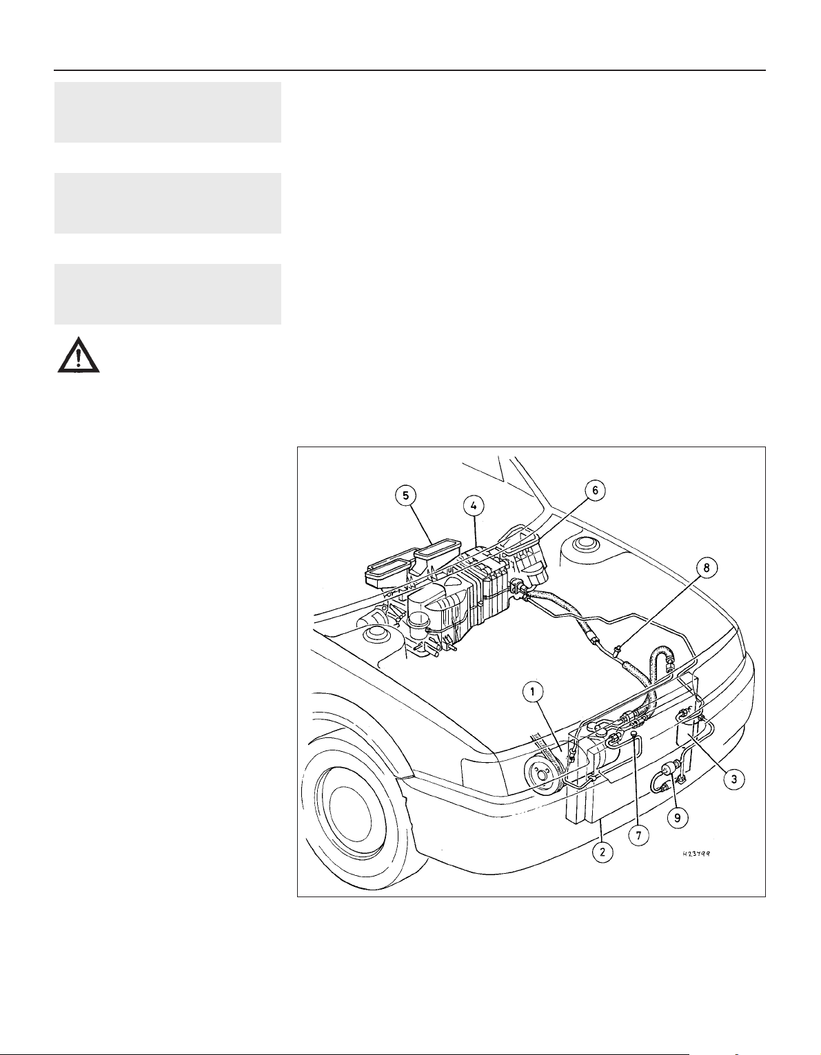
13 Air conditioning compressor
drivebelt - inspection,
adjustment and renewal
Refer to Chapter 1 (alternator drivebelt check).
14 Air conditioning refrigerant -
level check
Refer to Chapter 1.
15 Air conditioning system
components -
removal and refitting
3
Warning: The air conditioning
system must be professionally
discharged before carrying out
any of the following work. Cap
or plug the pipe lines as soon as they are
disconnected to prevent the entry of
moisture.
Compressor
Removal
1 Remove the alternator/air conditioning
compressor drivebelt as described in Chapter 1.
2 Disconnect the air conditioning pipes from
the compressor (see illustration).
3 Slacken and remove the four bolts securing
the compressor to the mounting bracket and
manoeuvre it downwards and away from the
engine.
Refitting
4 Refitting is a reverse of the removal
sequence, tightening the compressor
mounting bolts to the specified torque setting.
Ensure that the compressor pipe unions are
securely tightened then refit and adjust the
drivebelt as described in Chapter 1. On
completion, have the air conditioning system
recharged by a refrigeration specialist or
suitably-equipped Rover dealer.
Condenser
Removal
5 Remove the front bumper.
6 Slacken and remove the bolts securing the
power steering oil cooler to the body, then
undo the bonnet lock mounting bracket bolts
and position the lock assembly clear of the
condenser unit.
7 Unscrew the air conditioning pipe union
nuts from the condenser unit then disconnect
the pipes. Discard the union pipe O-rings as
these must be renewed whenever they are
disturbed.
8 Slacken and remove the four retaining bolts
and withdraw both the condenser upper
mounting brackets. Release the condenser
from its lower mounting points and
manoeuvre it away from the vehicle.
Refitting
9 Prior to refitting, check the condenser lower
mounting rubbers for signs of damage or
deterioration and renew as necessary. Renew
the pipe union O-rings.
10 Refitting is a direct reversal of the removal
procedure, tightening the pipe union nuts to
the specified torque setting. On completion,
have the air conditioning system recharged by
a refrigeration specialist or a suitably
equipped Rover dealer.
Condenser cooling fan
Removal
11 Drain the cooling system.
12 Disconnect the wiring connector from the
engine overheat switch, located in the top
coolant hose, then slacken the clips securing
the hose to the radiator and engine.
Disconnect the hose from the radiator and
engine and position it clear of the condenser
so that it does not hinder removal.
13 Disconnect the condenser fan electrical
wiring connector then undo the four fan
cowling retaining nuts and manoeuvre the
assembly out of the engine compartment.
14 To dismantle the assembly, first undo the
fan retaining nut then lift the fan off the motor
spindle. Undo the two screws which secure
the motor assembly to the cowling then
release the motor wiring and connector and
separate the motor and cowling.
Refitting
15 Refitting is a reverse of the removal
procedure, noting the following points:
a) Ensure that the motor wiring is securely
retained by the cowling clips and is clear
of the condenser fan.
b) Ensure that the radiator hose is securely
held by its retaining clips.
c) On completion, refill the cooling system.
Evaporator
Removal
16 Undo the three bolts which secure the
washer system reservoir to the engine
compartment bulkhead and move the
reservoir to gain access to the two evaporator
union nuts. Slacken both the union nuts and
disconnect the pipes from the evaporator.
Remove the O-rings from the union nuts and
discard them.
3•12 Cooling, heating and ventilation systems
15.2 Air conditioning system layout
1 Compressor
2 Condenser
3 Receiver drier
4 Evaporator
5 Heater unit
6 Blower unit
7 High pressure servicing
connection
8 Low pressure servicing
connection
9 Trinary switch
1689 Rover 214 & 414 Updated Version 09/97

17 Working from inside the vehicle, undo the
two glovebox retaining screws, then partially
withdraw the glovebox until access can be
gained to the glovebox damper-to-facia
screw. Undo the damper screw and remove
the glovebox and damper.
18 Slacken and remove the four glovebox
support rail mounting bolts and remove the
rail.
19 Undo the two evaporator bracket
retaining bolts and remove both the brackets.
20 Disconnect the wiring connector from the
right-hand side of the evaporator.
21 Slacken and remove the two evaporator
mounting nuts and manoeuvre the unit out of
position.
Refitting
22 Refitting is a reverse of the removal
procedure noting the following:
a) Ensure that the evaporator is correctly
joined to the heater unit and blower
motor, so that there are no air leaks or
gaps, then tighten the retaining nuts and
bracket bolts securely.
b) Fit new O-rings to the pipe unions and
tighten the union nuts to the specified
torque setting.
c) On completion, have the system
recharged by a refrigeration specialist or a
suitably-equipped Rover dealer.
Receiver drier
Removal
23 Remove the left-hand headlamp and the
battery and battery tray.
24 Undo the two screws securing the air
intake grille to the body. Disengage the grille
from the resonator and remove it from the
vehicle. Move the resonator to one side to
gain access to the receiver drier.
25 Slacken the union nuts and disconnect
the pipes from the receiver drier noting the Orings which are fitted to the pipe unions.
Discard the O-rings as they must be renewed
whenever they are disturbed. The receiver
drier unit unions must be capped immediately
after they are disconnected and must remain
capped until they are to be reconnected. If the
receiver drier unit is left uncapped for any
period of time it must be renewed.
26 Slacken the receiver drier clamp bolt then
slide the unit out of the retaining clamp and
remove it from the engine compartment.
Refitting
27 Refitting is a direct reversal of the removal
sequence, tightening the pipe union nuts to
the specified torque setting. On completion,
have the system recharged by a refrigeration
specialist or suitably-equipped Rover dealer.
Trinary switch
Removal
28 Remove the front bumper.
29 Disconnect the wiring connector and
unscrew the switch from the air conditioning
pipe. Remove the O-ring from the switch and
discard it.
Refitting
30 Refitting is a reverse of the removal
procedure. Fit a new O-ring to the switch and
tighten it to the specified torque setting. On
completion, have the system recharged by a
refrigeration specialist or suitably-equipped
Rover dealer.
Cooling, heating and ventilation systems 3•13
3
1689 Rover 214 & 414 Updated Version 09/97

3
1689 Rover 214 & 414 Updated Version 09/97
Chapter 3
Cooling, heating and ventilation systems
Air conditioning compressor drivebelt - inspection, adjustment
and renewal . . . . . . . . . . . . . . . . . . . . . . . . . . . . . . . . . . . . . . . . . . 13
Air conditioning refrigerant - level check . . . . . . . . . . . . . . . . . . . . . . 14
Air conditioning system components - removal and refitting . . . . . . 15
Coolant pump - removal and refitting . . . . . . . . . . . . . . . . . . . . . . . . 7
Cooling system - draining, flushing and filling . . . . . . . . . . . . . . . . . 2
Cooling system - general inspection . . . . . . . . . . . . . . . . . . . . . . . . . 3
Cooling system electrical switches - testing, removal and refitting . 9
Cooling system hoses - renewal . . . . . . . . . . . . . . . . . . . . . . . . . . . . 4
Electric cooling fan - testing, removal and refitting . . . . . . . . . . . . . . 8
General information and precautions . . . . . . . . . . . . . . . . . . . . . . . . 1
Heater components - removal and refitting . . . . . . . . . . . . . . . . . . . 10
Heater controls - removal, refitting and adjustment . . . . . . . . . . . . . 12
Heater ducts and vents - removal and refitting . . . . . . . . . . . . . . . . . 11
Radiator and expansion tank - removal, inspection and refitting . . . 5
Thermostat - removal, testing and refitting . . . . . . . . . . . . . . . . . . . . 6
3•1
Contents
Specifications
System
Type . . . . . . . . . . . . . . . . . . . . . . . . . . . . . . . . . . . . . . . . . . . . . . . . . . . . Pressurised, pump-assisted thermo-syphon with front mounted
radiator and thermostatically-controlled electric cooling fan
Thermostat
Type . . . . . . . . . . . . . . . . . . . . . . . . . . . . . . . . . . . . . . . . . . . . . . . . . . . . Wax
Start to open temperature . . . . . . . . . . . . . . . . . . . . . . . . . . . . . . . . . . . 76 to 80°C
Fully open temperature . . . . . . . . . . . . . . . . . . . . . . . . . . . . . . . . . . . . . . 82 or 88°C (actual value stamped in unit end)
Full lift height . . . . . . . . . . . . . . . . . . . . . . . . . . . . . . . . . . . . . . . . . . . . . 9.0 mm
Expansion tank
Cap pressure . . . . . . . . . . . . . . . . . . . . . . . . . . . . . . . . . . . . . . . . . . . . . 0.9 to 1.0 bar
Cooling fan
Operating temperature . . . . . . . . . . . . . . . . . . . . . . . . . . . . . . . . . . . . . . 88 to 92°C
Torque wrench settings Nm lbf ft
Cooling system
Fan motor nuts . . . . . . . . . . . . . . . . . . . . . . . . . . . . . . . . . . . . . . . . . . . . 5 4
Temperature gauge sender unit . . . . . . . . . . . . . . . . . . . . . . . . . . . . . . . 15 11
Thermostat housing cover bolts . . . . . . . . . . . . . . . . . . . . . . . . . . . . . . . 9 7
Thermostat housing/dipstick tube-to-cylinder block/crankcase bolt . . . 9 7
Coolant rail-to-cylinder block/crankcase bolts . . . . . . . . . . . . . . . . . . . . 9 7
Coolant pump-to-timing belt upper left-hand (inner) cover bolt . . . . . . 9 7
Coolant pump-to-cylinder block/crankcase bolts . . . . . . . . . . . . . . . . . 10 7
Heating system
Heater lower mounting nut . . . . . . . . . . . . . . . . . . . . . . . . . . . . . . . . . . . 21 15
Heater blower motor mounting bolts . . . . . . . . . . . . . . . . . . . . . . . . . . . 10 7
Air conditioning system
Compressor mounting bolts . . . . . . . . . . . . . . . . . . . . . . . . . . . . . . . . . . 45 33
Condenser unions . . . . . . . . . . . . . . . . . . . . . . . . . . . . . . . . . . . . . . . . . . 17 13
Evaporator inlet union (from receiver drier) . . . . . . . . . . . . . . . . . . . . . . 17 13
Evaporator outlet union . . . . . . . . . . . . . . . . . . . . . . . . . . . . . . . . . . . . . 33 24
Receiver drier union . . . . . . . . . . . . . . . . . . . . . . . . . . . . . . . . . . . . . . . . 17 13
Trinary switch . . . . . . . . . . . . . . . . . . . . . . . . . . . . . . . . . . . . . . . . . . . . . 12 9
Easy, suitable for
novice with little
experience
Fairly easy, suitable
for beginner with
some experience
Fairly difficult,
suitable for competent
DIY mechanic
Difficult, suitable for
experienced DIY
mechanic
Very difficult,
suitable for expert DIY
or professional
Degrees of difficulty
5
4
3
2
1
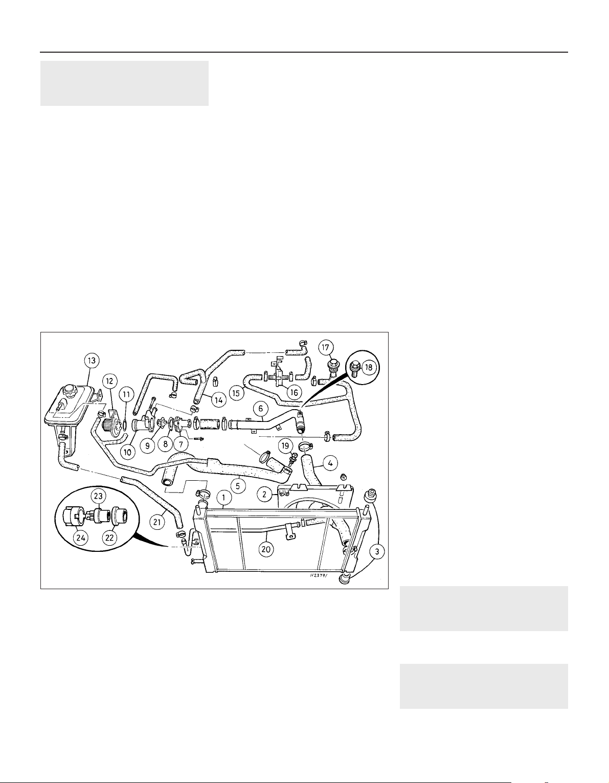
1 General information and
precautions
General information
The cooling system is of the pressurised,
pump-assisted thermo-syphon type. It
consists of the front-mounted radiator, a
translucent expansion tank mounted on the
right-hand inner wing, a thermostaticallycontrolled electric cooling fan mounted on the
rear of the radiator, a thermostat and a
centrifugal coolant pump, as well as the
connecting hoses (see illustration). The
coolant pump is driven by the engine timing
belt.
The system is of the by-pass type, allowing
coolant to circulate around the engine while
the thermostat is closed. With the engine
cold, the thermostat closes off the coolant
feed from the bottom radiator hose. Coolant is
then drawn into the engine via the heater
matrix, inlet manifold and from the top of the
cylinder block. This allows some heat transfer,
by convection, to the radiator through the top
hose whilst retaining the majority of heat
within the cylinder block.
The siting of the thermostat in the intake
rather than the outlet side of the system
ensures that the engine warms up quickly by
circulating a small amount of coolant around a
shorter tract. This also prevents temperature
build-up in the cylinder head prior to the
thermostat opening.
When the coolant reaches a predetermined
temperature, the thermostat opens and the
coolant is allowed to flow freely through the
top hose to the radiator. As the coolant
circulates through the radiator, it is cooled by
the inrush of air when the vehicle is in forward
motion. Airflow is supplemented by the action
of the electric cooling fan when necessary.
Upon reaching the bottom of the radiator, the
coolant is now cooled and the cycle is
repeated.
With the engine at normal operating
temperature, the coolant expands and some
of it is displaced into the expansion tank. This
coolant collects in the tank and is returned to
the radiator when the system cools.
The electric cooling fan mounted behind
the radiator is controlled by a thermostatic
switch located in the radiator side tank.
At a predetermined coolant temperature
the switch contacts close, thus actuating the
fan.
Precautions
Cooling system
Do not attempt to remove the expansion
tank filler cap or to disturb any part of the
cooling system whilst it or the engine is hot,
as there is a very great risk of scalding. If the
expansion tank filler cap must be removed
before the engine and radiator have fully
cooled down (even though this is not
recommended) the pressure in the cooling
system must first be released. Cover the cap
with a thick layer of cloth, to avoid scalding,
and slowly unscrew the filler cap until a
hissing sound can be heard. When the hissing
has stopped, showing that pressure is
released, slowly unscrew the filler cap until
it can be removed. If more hissing sounds
are heard, wait until they have stopped
before unscrewing the cap completely. At
all times keep well away from the filler
opening.
Do not allow antifreeze to come in contact
with your skin or painted surfaces of the
vehicle. Rinse off spills immediately with
plenty of water. Never leave antifreeze lying
around, it is fatal if ingested.
If the engine is hot, the electric cooling fan
may start rotating even if the engine is not
running, so be careful to keep hands, hair and
loose clothing well clear when working in the
engine compartment.
Air conditioning system
On models equipped with an air
conditioning system, it is necessary to
observe special precautions whenever dealing
with any part of the system, its associated
components and any items which necessitate
disconnection of the system. If for any reason
the system must be disconnected, entrust this
task to your Rover dealer or a refrigeration
engineer.
Refrigerant must not be allowed to come in
contact with a naked flame, otherwise a
poisonous gas will be created. Do not allow
the fluid to come in contact with the skin or
eyes.
2 Cooling system - draining,
flushing and refilling
Refer to Chapter 1.
3 Cooling system -
general inspection
Refer to “Weekly Checks” and Chapter 1.
3•2 Cooling, heating and ventilation systems
1.0 Cooling system components
1 Radiator
2 Cooling fan and cowling
3 Radiator mounting
rubbers
4 Bottom hose
5 Top hose
6 Coolant pipe - bottom
hose to thermostat
housing
7 Thermostat housing
cover
8 Gasket
9 Thermostat
10 Thermostat housing
11 O-ring
12 Coolant pump
13 Expansion tank
14 Hose - heater matrix and
manifold return
15 Hose - heater matrix and
manifold feed
16 Heater temperature
control valve
17 Coolant filler stem
18 Cooling system bleed
screw
19 Engine overheat switch -
where fitted
20 Coolant pipe - expansion
tank to bottom hose
21 Hose - expansion tank
return
22 Sealing ring
23 Cooling fan thermostatic
switch
24 Locking ring
1689 Rover 214 & 414 Updated Version 09/97
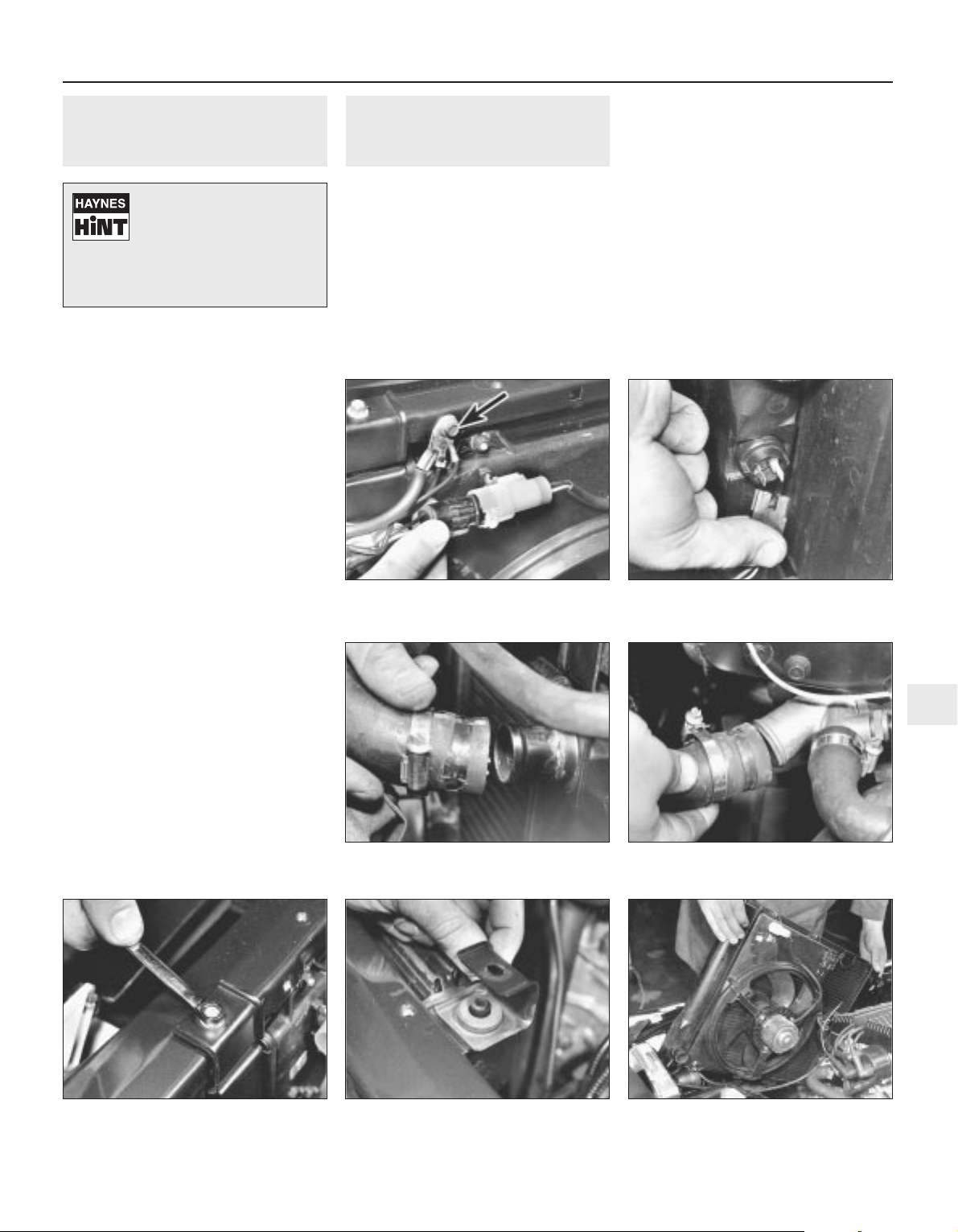
4 Cooling system hoses -
renewal
2
1 If inspection of the cooling system reveals a
faulty hose, then it must be renewed as
follows.
2 First drain the cooling system. If the coolant
is not due for renewal, it may be re-used if
collected in a clean container.
3 To disconnect any hose, use a screwdriver
to slacken the clips then move them along the
hose clear of the outlet. Carefully work the
hose off its outlets. Do not attempt to
disconnect any part of the system when still
hot.
4 Note that the radiator hose outlets are
fragile. Do not use excessive force when
attempting to remove the hoses. If a hose
proves stubborn, try to release it by rotating it
on its outlets before attempting to work it off.
If all else fails, cut the hose with a sharp knife
then slit it so that it can be peeled off in two
pieces. While expensive, this is preferable to
buying a new radiator.
5 When refitting a hose, first slide the clips
onto the hose then work the hose onto its
outlets. If the hose is stiff, use soap as a
lubricant or soften it by first soaking it in
boiling water whilst taking care to prevent
scalding.
6 Work each hose end fully onto its outlet,
check that the hose is settled correctly and is
properly routed, then slide each clip along the
hose until it is behind the outlet flared end
before tightening it securely.
7 Refill the system with coolant.
8 Check carefully for leaks as soon as
possible after disturbing any part of the
cooling system.
5 Radiator and expansion tank
- removal, inspection and
refitting
2
Removal
Radiator
1 Drain the cooling system.
2 On models equipped with air conditioning,
remove the condenser fan, then undo the two
bolts securing the air conditioning pipes to the
bonnet platform.
3 Remove the air cleaner metal intake duct
and intake hose.
4 Disconnect the radiator cooling fan wiring
connector, then slacken and remove the bolt
securing the earth leads to the bonnet platform.
Disconnect the wiring from the thermostatic
switch(es) which are fitted to the right-hand
side of the radiator (see illustrations).
5 Slacken the bottom hose retaining clip and
disconnect the hose from the radiator.
6 Slacken the retaining clips and disconnect
the top hose from both the radiator and
engine coolant elbow (see illustrations).
Position the hose clear of the radiator so that
it does not hinder removal.
7 Undo the two bolts securing the upper
mounting brackets to the bonnet platform and
remove the brackets from the radiator.
Disengage the radiator from its lower mounting
points and carefully manoeuvre it out of the
engine compartment (see illustrations).
Cooling, heating and ventilation systems 3•3
5.6a Slacken clips and disconnect top
hose from radiator . . .
5.4b Disconnecting wiring connector from
radiator switch
5.7a Undo radiator mounting bolts . . .
5.6b . . . and engine coolant elbow
5.7c . . . and manoeuvre radiator out of
engine compartment
5.7b . . . remove mounting brackets . . .
5.4a Disconnect cooling fan wiring
connector then remove earth lead
retaining bolt (arrowed)
3
1689 Rover 214 & 414 Updated Version 09/97
Never work on the cooling
system when it is hot.
Release any pressure from
the system by loosening the
expansion tank cap, having first
covered it with a cloth to avoid any
possibility of scalding.

Expansion tank
8 Slacken and remove the three bolts
securing the expansion tank to the body.
Unscrew the expansion tank cap and tip out
its contents into a suitable container.
9 Slacken the retaining clips then disconnect
both the hoses from the expansion tank and
remove the tank from the vehicle.
Inspection
Radiator
10 If the radiator was removed because of
clogging (causing overheating) then try
reverse flushing or, in severe cases, use a
radiator cleanser strictly in accordance with
the manufacturer’s instructions. Ensure
that the cleanser is suitable for use in a
copper/brass radiator. Refer to Chapter 1 for
further information
11 Use a soft brush and an air line or garden
hose to clear the radiator matrix of leaves,
insects etc.
12 Major leaks or extensive damage should
be repaired by a specialist, or the radiator
should be renewed or exchanged for a
reconditioned unit.
13 Examine the mounting rubbers for signs
of damage or deterioration and renew if
necessary.
Expansion tank
14 Empty any remaining coolant from the
tank and flush it with fresh water to clean it. If
the tank is leaking it must be renewed but it is
worth first attempting a repair using a
proprietary sealant or suitable adhesive.
15 The expansion tank cap should be
cleaned and checked whenever it is removed.
Check that its sealing surfaces and threads
are clean and undamaged and that they mate
correctly with those of the expansion tank.
16 The cap’s performance can only be
checked by using a cap pressure-tester
(cooling system tester) with a suitable
adaptor. On applying pressure, the cap’s
pressure relief valve should hold until the
specified pressure is reached, at which point
the valve should open.
17 If there is any doubt about the cap’s
performance, then it must be renewed. Ensure
that the replacement is of the correct type and
rating.
Refitting
Radiator
18 Refitting is the reverse of the removal
procedure whilst noting the following:
a) Ensure that the radiator is seated
correctly and without strain on its
mountings.
b) Ensure that the radiator hoses are
securely held by the retaining clips.
c) Ensure that all wiring connectors are
correctly routed so that they are clear of
the cooling fan and are retained by any
necessary clips or ties.
d) Refill the cooling system as described in
Chapter 1.
Expansion tank
19 Refitting is the reverse of the removal
procedure whilst noting the following:
a) Ensure that all hoses are correctly routed
with no kinks or sharp bends and are
securely held by the retaining clips.
b) Top up the expansion tank as described
in Chapter 1.
6 Thermostat -
removal, testing and refitting
3
Removal
1 Note that access to the thermostat is very
limited. Depending on the tools available, it
may be easier to raise the front of the vehicle
and to work from underneath, ensuring that
the vehicle is securely supported on axle
stands. In most cases, access is better if the
air cleaner and carburettor (or throttle body on
SPi engines) are removed and is best if the
complete inlet manifold is removed. If the inlet
manifold is removed, the thermostat housing
cover can be unbolted to remove the
thermostat without disturbing the housing
itself (see illustration). Whichever method is
used, first drain the cooling system.
2 On carburettor models equipped with a
catalytic converter, either remove the
thermostatically-operated vacuum switch or
disconnect the vacuum pipes from the switch
so that it can be removed with the thermostat
housing.
3 Unbolt the coolant rail from the rear of the
cylinder block/crankcase, then slacken the
clips and disconnect the coolant rail hose and
heater/inlet manifold return hose from the
thermostat housing (see illustration).
4 Undo the thermostat housing/dipstick tubeto-cylinder block/crankcase bolt and remove
the thermostat housing from the cylinder
block/crankcase. Remove the housing O-ring
which must be renewed whenever it is
disturbed (see illustrations).
5 Slacken and remove the three thermostat
housing cover bolts and lift off the housing
cover. Discard the gasket and remove the
thermostat.
Testing
6 If the thermostat remains in the open
position at room temperature, then it is faulty
and must be renewed.
7 To test it fully, suspend the (closed)
thermostat on a length of string in a container
of cold water, with a thermometer beside it.
3•4 Cooling, heating and ventilation systems
6.4b . . . and withdraw thermostat housing
(O-ring arrowed) – inlet manifold removed
for clarity
6.4a . . . unscrew dipstick tube retaining
bolt . . .
6.3 Disconnect coolant rail and
heater/inlet manifold hoses (arrowed) . . .
6.1 Thermostat can be removed without
disturbing housing if inlet manifold is first
removed
1689 Rover 214 & 414 Updated Version 09/97
Minor leaks from the
radiator can be cured using
a suitable sealant with the
radiator in situ.

Ensure that neither touches the side of the
container (see illustration).
8 Heat the water and check the temperature
at which the thermostat begins to open.
Compare this value with that specified.
Continue to heat the water until the
thermostat is fully open. The temperature at
which this should happen is stamped in the
unit’s end (see illustration). Remove the
thermostat and measure the height of the fully
opened valve, then allow the thermostat to
cool down and check that it closes fully.
9 If the thermostat does not open and close
as described, if it sticks in either position, or if
it does not open at the specified temperature,
then it must be renewed.
Refitting
10 Refitting is the reverse of the removal
procedure, noting the following (see
illustration):
a) Clean the thermostat housing, housing
cover and cylinder block/crankcase
mating surfaces thoroughly.
b) Always fit a new housing cover gasket
and O-ring. Smear the O-ring with grease
to aid refitting.
c) Tighten all bolts to their specified torque
wrench settings (where given).
d) Ensure the coolant hose clips are
positioned so that they do not foul any
other component, then tighten them
securely.
e) Refit any components removed for
improved access.
f) Refill the cooling system as described in
Chapter 1.
7 Coolant pump -
removal and refitting
4
Removal
1 Coolant pump failure is usually indicated by
coolant leaking from the gland behind the
pump bearing, or by rough and noisy
operation, usually accompanied by excessive
pump spindle play. If the pump shows any of
these symptoms then it must be renewed as
follows.
2 Drain the cooling system.
3 Remove the timing belt.
4 Noting the location of the pillar bolt(s),
unscrew the five bolts securing the coolant
pump to the cylinder block/crankcase, then
unscrew the single bolt securing the pump to
the timing belt upper left-hand (inner) cover.
5 Withdraw the coolant pump and discard its
sealing ring which should be renewed
whenever it is disturbed. Carefully clean the
cylinder block/crankcase mating surface and
the pump socket (see illustration).
Refitting
6 On refitting, install the pump using a new
sealing ring and tighten all bolts to the
specified torque wrench settings.
7 The remainder of the refitting procedure is
the reverse of removal.
8 Electric cooling fan -
testing, removal and refitting
2
Note: On models equipped with air
conditioning, there are two switches fitted to
the right-hand side of the radiator, the lower of
these is the cooling fan switch.
Testing
1 The cooling fan motor is supplied with
current via the ignition switch, fuse 4 and the
cooling fan relay. The relay is energised by the
radiator-mounted thermostatic switch which
is fed via fuse number 15.
2 If the fan does not appear to work, first
check that both fuses are in good condition
and have not blown. Run the engine until
normal operating temperature is reached,
then allow it to idle. If the fan does not cut in
within a few minutes, switch off the ignition
and disconnect the two wires from the
thermostatic switch. Bridge these two wires
with a length of spare wire and switch on the
ignition. If the fan now operates, the
thermostatic switch is probably faulty and
must be tested further as described in
Section 9.
3 If the fan still fails to operate, check that full
battery voltage is available at the switch’s
light green and grey wire terminal. If not,
check the feed for a blown fuse or other fault
such as a broken wire. If the feed is good,
check the cooling fan relay, see Chapter 12. If
the relay operates correctly, check for
continuity between the fan motor black wire
terminal and a good earth point on the body. If
not, then the earth connection is faulty and
must be remade. The circuit earth connection
is one of those at earth header 1, attached to
the left-hand inner wing panel next to the
battery.
4 If the switch and wiring are in good
condition, the fault must be in the motor itself.
This can be checked by disconnecting it from
the wiring loom and connecting a 12 volt
supply directly to it. If the motor does not
work then it must be renewed.
Removal
5 Drain the cooling system, then jack up the
front of the vehicle and support it securely on
axle stands.
6 From underneath the front of the vehicle,
slacken and remove the three bolts securing
the bumper flange to the body. Remove the
seven bolts securing the front undercover
panel to the body and remove the panel.
7 Remove the air cleaner metal intake duct
and intake hose.
8 Slacken the retaining clips and disconnect
the top hose from both the radiator and
engine. Position the hose clear of the radiator
so that it does not hinder removal.
9 Disconnect the radiator cooling fan wiring
connector.
Cooling, heating and ventilation systems 3•5
6.10 Thermostat housing and coolant
hoses refitted
6.8 Note temperature specification
stamped on thermostat end
6.7 Testing the thermostat
7.5 Removing the coolant pump
3
1689 Rover 214 & 414 Updated Version 09/97

10 Undo the four nuts securing the cooling
fan cowling to the rear of the radiator and
manoeuvre the fan assembly out of the engine
compartment (see illustrations).
11 To dismantle the assembly, first prise off
the fan retaining circlip, then lift the fan off the
motor spindle. Undo the three nuts which
secure the motor assembly to the cowling
then release the motor wiring and connector
and separate the motor and cowling (see
illustration).
Refitting
12 Refitting is a reverse of the removal
procedure, noting the following:
a) If necessary, reassemble the fan motor,
cowling and fan, then tighten the motor
retaining nuts to the specified torque.
Ensure that the motor wiring is securely
retained by the cowling clips.
b) Ensure that the radiator hose is securely
held by its retaining clips.
c) On completion, refill the cooling system
as described in Chapter 1.
9 Cooling system electrical
switches - testing, removal
and refitting
2
Note: On models equipped with air
conditioning, there are two switches fitted to
the right-hand side of the radiator, the lower of
these is the cooling fan switch.
Testing
Cooling fan thermostatic switch
1 Refer to Section 8 for details of a quick test
which should eliminate most faulty switches.
If the switch is to be renewed, or to be tested
thoroughly, it must be removed.
2 To carry out a thorough test of the switch,
use two spare wires to connect to it either a
multimeter (set to the resistance function) or a
battery and bulb test circuit. Suspend the
switch in a pan of water which is being
heated. Measure the temperature of the water
with a thermometer. Do not let either the
switch or the thermometer touch the pan itself
(see illustration).
3 The switch contacts should close to the ON
position (ie: continuity should exist) when the
water reaches the temperature specified.
Stop heating the water and allow it to cool
down. The switch contacts should open.
4 If the switch’s performance is significantly
different from that specified, or if it does not
work at all, then it must be renewed.
Coolant temperature gauge sender
unit
5 The coolant temperature gauge mounted in
the instrument panel is fed with a stabilised 10
volt supply from the instrument panel feed (via
the ignition switch and fuse 1), its earth being
controlled by the sender unit.
6 The sender unit is screwed into the coolant
outlet elbow mounted on the left-hand end of
the cylinder head, underneath the distributor
(see illustration). It contains a thermistor,
which is an element whose electrical
resistance decreases at a predetermined rate
as its temperature rises. Thus, when the
coolant is cold, the sender’s resistance is
high, current flow through the gauge is
reduced and the gauge needle points to the
C (cold) end of the scale. If the unit is faulty it
must be renewed.
7 If the gauge develops a fault, check first the
other instruments. If they do not work at all,
check the instrument panel feed. If the
readings are erratic, there may be a fault in the
voltage stabiliser which will necessitate the
renewal of the gauge unit or printed circuit. If
the fault is in the temperature gauge alone,
check it as follows.
8 If the gauge needle remains at the C end of
the scale, disconnect the sender unit wire and
earth it to the cylinder head. If the needle then
deflects when the ignition is switched on, then
the sender unit is proven faulty and must be
renewed. If the needle still does not move,
remove the instrument panel and check the
continuity of the green/blue wire between the
gauge and the sender unit and the feed to
the gauge unit. If continuity is shown and the
fault still exists, then the gauge is faulty and
the gauge unit must be renewed.
9 If the gauge needle remains at the H end of
the scale, disconnect the sender unit wire. If
the needle then returns to the C end of the
scale when the ignition is switched on, then
the sender unit is proven faulty and must be
renewed. If the needle still does not move,
check the remainder of the circuit as
described above.
Inlet manifold pre-heater temperature
switch - carburettor engines
10 The switch screwed into the underside of
the inlet manifold on carburettor engines
3•6 Cooling, heating and ventilation systems
9.6 Coolant temperature gauge sender
unit
9.2 Testing cooling system electrical
switch
8.11 Cooling fan motor retaining nuts
(arrowed)
8.10b . . . and remove fan assembly8.10a Undo cooling fan cowling retaining
nuts (2 arrowed) . . .
1689 Rover 214 & 414 Updated Version 09/97
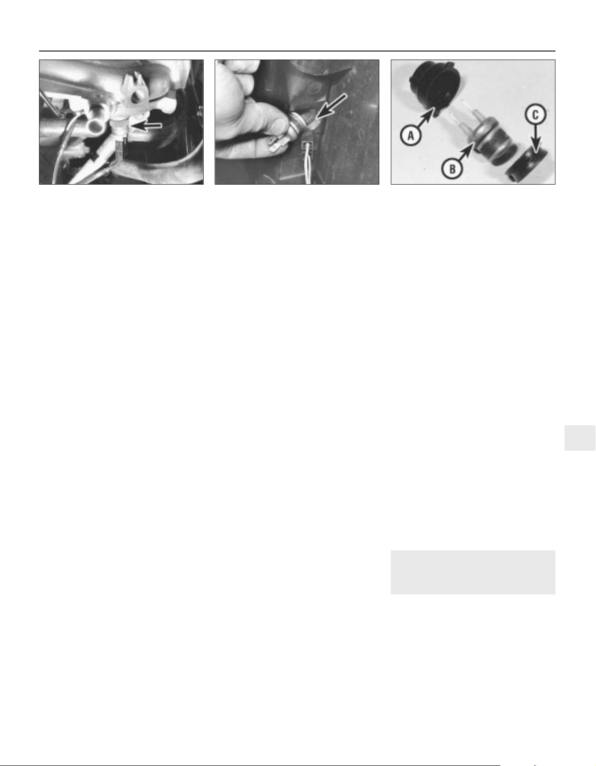
controls the inlet manifold heater circuit (see
illustration).
11 The switch contacts should be closed to
the ON position (ie: continuity should exist)
only at temperatures below 50°C. Remove the
switch and test it as described in paragraphs 2 to 4.
Thermostatically-operated vacuum
switch - carburettor engines equipped
with catalytic converters
12 This switch is screwed into the thermostat
housing.
13 To test the switch, fit two suitable lengths
of hose to the switch and suspend the switch
in a pan of water which is being heated.
Measure the temperature of the water
with a thermometer. Do not let either the
switch or the thermometer touch the pan
itself.
14 Blow down one of the hoses attached to
the switch. The switch should be closed (ie:
passes no air) when the water temperature is
below 70°C. Above 70°C, the switch should
open and air should flow freely through the
hoses. Stop heating the water then allow the
water to cool down and check that the switch
closes at 70°C or just below.
15 If the switch performance is significantly
different from that specified, or if it does not
work at all, then it must be renewed.
Coolant temperature sensor - fuel
injected engines
16 This sensor, which is screwed into the
underside of the inlet manifold (SPi engines),
or located in the coolant pipe adjacent to the
foward top edge of the timing belt cover (MPi
engines), is a thermistor (see paragraph 6)
which is supplied with approximately 5 volts
by the engine management system ECU. The
ECU also controls the sensor’s earth path
and, by measuring the amount of current in
the sensor circuit, determines the engine’s
temperature. This information is used, in
conjunction with other inputs, to control idle
speed, injector opening time duration and
ignition timing.
17 If the sensor circuit should fail to provide
adequate information, the ECU’s back-up
facility assumes a value corresponding to
60°C. The sensor itself can be tested only by
having a Rover dealer check the complete
system using the correct diagnostic
equipment. Do not attempt to test the circuit
using any other equipment, or the ECU will be
damaged.
Removal
Cooling fan thermostatic switch
18 With the engine and radiator cold, either
drain the cooling system down to the level of
the sender unit, or unscrew the expansion
tank filler cap to release any remaining
pressure and have a suitable plug ready that
can be used to stop the escape of coolant
while the switch is removed.
19 Disconnect the battery negative lead.
20 Disconnect the wiring connector from the
switch then rotate the locking ring to release
it. Withdraw the switch and sealing ring from
the radiator (see illustration).
Coolant temperature gauge sender
unit
21 With the engine and radiator cold, either
drain the cooling system down to the level of
the switch, or unscrew the expansion tank
filler cap to release any remaining pressure
and have a suitable plug ready that can be
used to stop the escape of coolant while the
unit is removed.
22 Disconnect the battery negative lead.
23 Disconnect the unit’s wiring connector
and unscrew the unit from the coolant outlet
elbow.
Inlet manifold pre-heater temperature
switch - carburettor engines
24 Refer to Chapter 4.
Thermostatically-operated vacuum
switch - carburettor engines equipped
with catalytic converters
25 Refer to Chapter 5.
Coolant temperature sensor - fuel
injected engines
26 Refer to Chapter 4.
Refitting
Cooling fan thermostatic switch
27 On refitting, renew the sealing ring if it is
worn or compressed and carefully clean the
radiator seat before pressing in the
sealing ring and switch (see illustration).
Refit the locking ring and rotate it to
tighten it securely. Reconnect the switch
and battery, then replenish the cooling
system.
Coolant temperature gauge sender
unit
28 On refitting, apply a suitable sealant to the
unit threads and tighten it to its specified
torque wrench setting. Reconnect the unit
and battery, then replenish the cooling
system.
Inlet manifold pre-heater temperature
switch - carburettor engines
29 Refer to Chapter 4.
Thermostatically-operated vacuum
switch - carburettor engines equipped
with catalytic converters
30 Refer to Chapter 5.
Coolant temperature sensor - fuel
injected engines
31 Refer to Chapter 4.
10 Heater components -
removal and refitting
3
Removal
Heater unit
1 Drain the cooling system.
2 Working in the engine compartment,
slacken the hose clips and disconnect the
heater feed and return hoses from the matrix
outlets on the bulkhead. Disconnect the cable
inner from the heater valve and free the cable
outer from its retaining clip. Slacken and
Cooling, heating and ventilation systems 3•7
9.27 Cooling fan switch locking ring (A)
thermostatic switch (B) and sealing
ring (C)
9.20 Remove cooling fan thermostatic
switch and withdraw sealing ring
(arrowed)
9.10 Inlet manifold pre-heater temperature
switch (carburettor engines)
3
1689 Rover 214 & 414 Updated Version 09/97

remove the heater lower mounting nut which
is situated just to the left of the matrix outlets
(see illustrations).
3 Working inside the vehicle, remove the
facia.
4 Slacken and remove the two retaining
screws and remove the blower motor-toheater unit duct (see illustration). On models
equipped with air conditioning, the evaporator
unit is fitted in place of the duct. It may be
possible to gain the necessary clearance
required to disengage the evaporator from the
heater unit by removing the mounting
brackets and nuts. If not, the evaporator must
be removed.
5 Undo the screw securing the right-hand
heater duct to the mounting bracket, then
move the duct to the right to disengage it from
the heater unit (see illustrations).
6 Undo the inertia switch retaining nut and
disengage the switch from the steering
column support bracket.
7 Release the wiring block connector from
the right-hand end of the steering column
support bracket and undo the fusebox
3•8 Cooling, heating and ventilation systems
10.5a Undo right-hand duct retaining
screw (arrowed) . . .
10.2c . . . and free heater valve cable from
retaining clip
10.2d Slacken and remove heater unit
lower mounting nut
10.4 Remove blower motor-to-heater unit
duct
10.2b Disconnect heater feed and return
hoses . . .
10.2a Heater unit components
1 Heater case
2 Heater case clip
3 Face level/windscreen
duct
4 Floor level duct
5 Heater matrix
6 Heater matrix cover
7 Cable retaining clip
8 Floor level flap operating
lever
9 Clip
10 Floor level flap idler lever
11 Face level flap idler lever
12 Flap operating lever
13 Air mix flap operating lever
14 Air mix flap
15 Ambient air flap - centre
console vents
16 Distribution flap -
windscreen
17 Distribution flap - face
level vents
18 Distribution flap - floor
level vents
1689 Rover 214 & 414 Updated Version 09/97
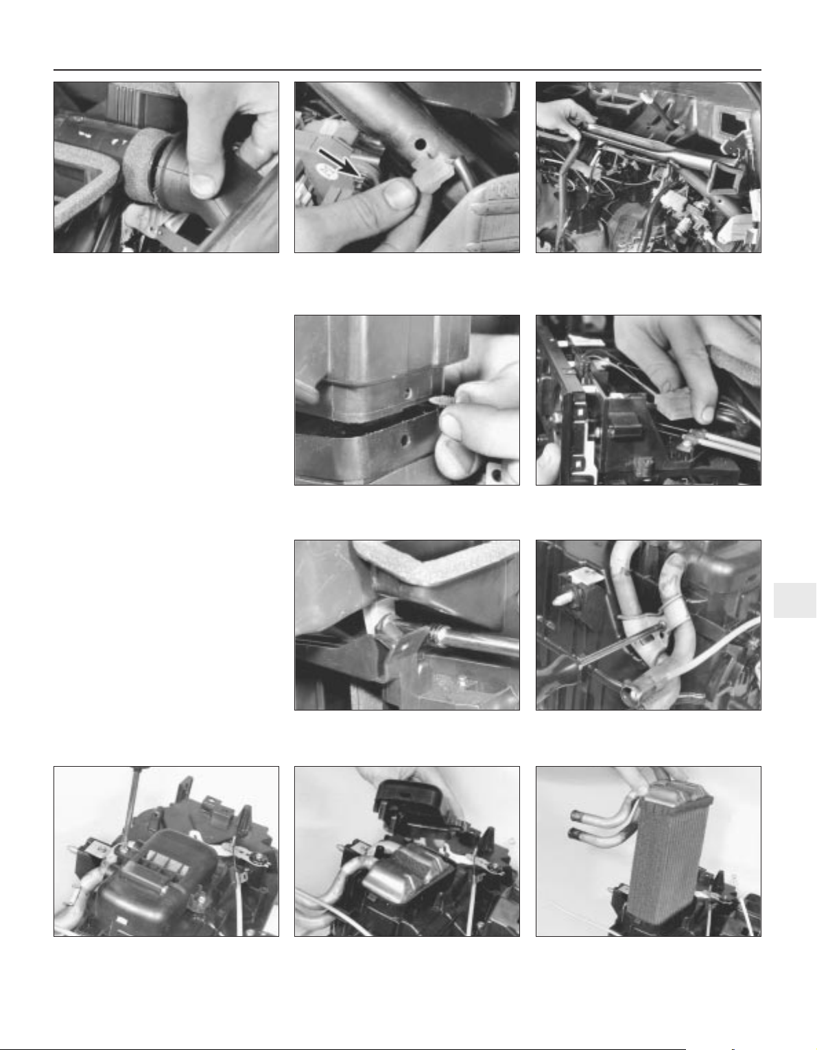
retaining nut. Slacken and remove the five
support bracket retaining bolts and remove
the bracket from the vehicle (see
illustrations).
8 Disconnect the air recirculation cable inner
from the flap and free the cable outer from the
blower motor.
9 Prise out the stud securing the rear heater
duct sleeve to the bottom of the heater unit,
then slide the sleeve down to disengage it
from the unit (see illustration).
10 Disconnect the wiring connectors from
the heater control panel, then remove the two
upper heater unit retaining nuts and carefully
manoeuvre the heater unit out of the vehicle
(see illustrations).
Heater matrix
11 Remove the heater unit.
12 Undo the screw securing the matrix outlet
pipe bracket to the heater unit and remove the
bracket (see illustration).
13 Slacken and remove the two matrix cover
retaining screws, then remove the cover and
withdraw the matrix from the heater unit (see
illustrations).
14 If the matrix is leaking, it is best to obtain
a new or reconditioned unit as home repairs
are seldom successful. If it is blocked, it can
sometimes be cleared by reverse flushing
using a garden hose. Use a proprietary
radiator cleaning product if absolutely
necessary.
Cooling, heating and ventilation systems 3•9
10.7b Remove mounting bolts and
manoeuvre steering column mounting
bracket out of position
10.7a Release wiring connector from
steering column support bracket and
remove fusebox nut (arrowed)
10.5b . . . and disengage duct from heater
unit
10.13c . . . and withdraw matrix from
heater unit
10.13b . . . then remove cover . . .
10.12 Undo retaining screw and remove
matrix outlet pipe bracket
10.10b . . . and remove heater retaining
nuts
10.10a Disconnect wiring from heater
control panel . . .
10.9 Remove retaining stud and disengage
rear heater duct sleeve from heater unit
10.13a Undo two matrix cover retaining
screws . . .
3
1689 Rover 214 & 414 Updated Version 09/97

Heater blower motor
15 Undo the two glovebox retaining screws
then partially withdraw the glovebox until
access can be gained to the glovebox damper
to facia screw. Undo the damper screw and
remove the glovebox and damper (see
illustration).
16 Slacken and remove the four glovebox
support rail mounting bolts and remove the
rail (see illustration).
17 Slacken and remove the two retaining
screws and remove the blower motor-toheater unit duct (see illustration). On models
equipped with air conditioning, the evaporator
unit is fitted in place of the duct. It may be
possible to gain the necessary clearance
required to disengage the evaporator and
remove the blower motor by removing the
mounting brackets and nuts. If not, the
evaporator must be removed.
18 Disconnect the air recirculation cable
inner from the flap and free the cable outer
from the blower motor. Disconnect the two
blower motor wiring connectors (see
illustration).
19 Slacken and remove the three blower
motor mounting bolts and manoeuvre the
blower unit out from underneath the facia (see
illustrations).
20 To remove the motor from the unit, undo
the four motor cover retaining screws, then
disconnect the breather hose and lift off the
cover. Slacken and remove the three motor
retaining bolts and withdraw the motor
assembly from the blower unit. Undo the fan
retaining nut and separate the fan and motor,
noting the seal fitted between the two
components (see illustrations).
Heater blower motor resistor
21 Remove the glovebox as described in
paragraphs 15 and 16.
22 Disconnect the wiring connector, then
undo the two retaining screws and remove the
resistor from the front of the motor assembly.
Heater valve
23 Working in the engine compartment,
disconnect the cable inner from the heater
3•10 Cooling, heating and ventilation systems
10.20c Undo motor retaining bolts and
withdraw motor from unit
10.20b . . . and disconnect breather hose10.20a Remove motor cover retaining
screws (arrowed) . . .
10.19b . . . and remove unit from behind
facia
10.19a Undo three blower motor mounting
bolts (arrowed) . . .
10.18 Disconnect motor wiring connectors (A) and air recirculation cable (B)
10.17 . . . then remove blower motor-toheater unit duct
10.16 Remove glovebox support rail . . .10.15 Glovebox damper retaining screw
(arrowed)
1689 Rover 214 & 414 Updated Version 09/97
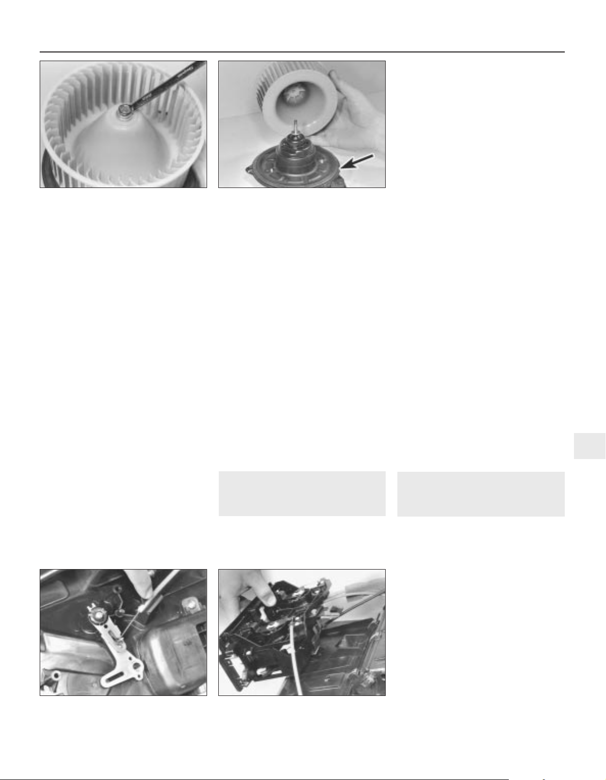
valve and free the cable outer from the
retaining clip.
24 Slacken and remove the bolt securing the
heater valve mounting bracket to the engine
compartment bulkhead.
25 Either drain the cooling system or clamp
the coolant hoses on each side of the coolant
valve to minimise the loss of coolant.
26 Slacken the hose retaining clips, then
disconnect both hoses from the coolant valve
and remove the valve from the engine
compartment. Mop up any spilt coolant
immediately.
Refitting
Heater unit
27 Refitting is a reverse of the removal
procedure, noting the following:
a) Ensure that the heater ducts are securely
connected to the unit so that there are no
air leaks or gaps.
b) Check the operation of all heater cables
before refitting the facia, ensuring that the
relevant component moves smoothly from
the fully open to the fully closed position.
If necessary, adjustments can be made by
releasing the relevant retaining clip and
repositioning the cable outer.
c) Ensure that the heater hoses are correctly
reconnected and are securely held by the
retaining clips.
d) Tighten the heater lower mounting nut to
the specified torque setting.
e) Refill the cooling system as described in
Chapter 1.
Heater matrix
28 Refitting is a reverse of the removal
procedure.
Heater blower motor
29 Refitting is a reversal of the removal
sequence, noting the following:
a) Ensure that the foam rubber seal is
refitted correctly so that the blower
motor-to-bulkhead aperture is closed off.
b) Tighten the blower motor mounting bolts
to the specified torque setting.
c) Ensure that the air recirculation cable and
flap functions correctly before refitting the
glovebox. If necessary, adjust by releasing
the cable retaining clip and repositioning
the cable outer.
Heater blower motor resistor
30 Refitting is a reverse of the removal
procedure.
Heater valve
31 Refitting is a reversal of the removal
procedure. On completion, check the heater
cable operates smoothly and replenish the
cooling system.
11 Heater ducts and vents -
removal and refitting
3
Removal
Facia ducts
1 Remove the facia.
2 The ducts are mounted on the facia
assembly and can be removed individually,
once the retaining screws have been
removed.
Heater unit ducts
3 The left-hand heater unit to blower
motor duct is removed as described in
paragraphs 15 to 17 of Section 10.
4 To remove the right-hand duct, first remove
the facia. Slacken and remove the retaining
screw which secures the right-hand end of the
duct to the mounting bracket and release the
radio aerial from the retaining clips on the
underside of the duct. The duct can then be
manoeuvred out of position.
5 Removal of the lower ducts which supply
air to the rear passenger footwells is a
complex job, requiring the removal of the front
seats, centre console and the various trim
panels so that the floor carpet can be peeled
back, and is therefore not recommended.
Centre console vents
6 Remove the centre console.
7 The vents can then be unclipped from the
rear of the front console section and removed.
Facia vents
8 The adjustable face-level vents can be
removed by prising them gently out of the
facia until the clips are released, taking care
not to mark the facia.
9 The door window demister vents, fitted to
the sides of the facia, can also be prised out
of position once the relevant door has been
opened.
Refitting
10 Refitting is a reverse of the removal
procedure.
12 Heater controls - removal,
refitting and adjustment
3
Removal
1 Remove the heater unit.
2 Disconnect the heater control cables from
the heater unit and unclip the control panel.
Remove the panel assembly complete with
cables (see illustrations).
Refitting and adjustment
3 Refit the heater control panel to the heater
unit and reconnect the necessary control
cables to their original positions.
4 Check the operation of the control cables,
ensuring that they operate smoothly and
move the necessary component from the fully
open to the fully closed position. Adjustments
can be made by releasing the cable retaining
clip and repositioning the cable outer.
5 Once the necessary control cables are
functioning correctly, refit the heater unit.
Cooling, heating and ventilation systems 3•11
10.20e . . . and lift off fan (seal arrowed)10.20d Remove fan retaining nut . . .
12.2b . . . and remove heater control panel
with cables
12.2a Disconnect control cables from
heater unit . . .
3
1689 Rover 214 & 414 Updated Version 09/97

13 Air conditioning compressor
drivebelt - inspection,
adjustment and renewal
Refer to Chapter 1 (alternator drivebelt check).
14 Air conditioning refrigerant -
level check
Refer to Chapter 1.
15 Air conditioning system
components -
removal and refitting
3
Warning: The air conditioning
system must be professionally
discharged before carrying out
any of the following work. Cap
or plug the pipe lines as soon as they are
disconnected to prevent the entry of
moisture.
Compressor
Removal
1 Remove the alternator/air conditioning
compressor drivebelt as described in Chapter 1.
2 Disconnect the air conditioning pipes from
the compressor (see illustration).
3 Slacken and remove the four bolts securing
the compressor to the mounting bracket and
manoeuvre it downwards and away from the
engine.
Refitting
4 Refitting is a reverse of the removal
sequence, tightening the compressor
mounting bolts to the specified torque setting.
Ensure that the compressor pipe unions are
securely tightened then refit and adjust the
drivebelt as described in Chapter 1. On
completion, have the air conditioning system
recharged by a refrigeration specialist or
suitably-equipped Rover dealer.
Condenser
Removal
5 Remove the front bumper.
6 Slacken and remove the bolts securing the
power steering oil cooler to the body, then
undo the bonnet lock mounting bracket bolts
and position the lock assembly clear of the
condenser unit.
7 Unscrew the air conditioning pipe union
nuts from the condenser unit then disconnect
the pipes. Discard the union pipe O-rings as
these must be renewed whenever they are
disturbed.
8 Slacken and remove the four retaining bolts
and withdraw both the condenser upper
mounting brackets. Release the condenser
from its lower mounting points and
manoeuvre it away from the vehicle.
Refitting
9 Prior to refitting, check the condenser lower
mounting rubbers for signs of damage or
deterioration and renew as necessary. Renew
the pipe union O-rings.
10 Refitting is a direct reversal of the removal
procedure, tightening the pipe union nuts to
the specified torque setting. On completion,
have the air conditioning system recharged by
a refrigeration specialist or a suitably
equipped Rover dealer.
Condenser cooling fan
Removal
11 Drain the cooling system.
12 Disconnect the wiring connector from the
engine overheat switch, located in the top
coolant hose, then slacken the clips securing
the hose to the radiator and engine.
Disconnect the hose from the radiator and
engine and position it clear of the condenser
so that it does not hinder removal.
13 Disconnect the condenser fan electrical
wiring connector then undo the four fan
cowling retaining nuts and manoeuvre the
assembly out of the engine compartment.
14 To dismantle the assembly, first undo the
fan retaining nut then lift the fan off the motor
spindle. Undo the two screws which secure
the motor assembly to the cowling then
release the motor wiring and connector and
separate the motor and cowling.
Refitting
15 Refitting is a reverse of the removal
procedure, noting the following points:
a) Ensure that the motor wiring is securely
retained by the cowling clips and is clear
of the condenser fan.
b) Ensure that the radiator hose is securely
held by its retaining clips.
c) On completion, refill the cooling system.
Evaporator
Removal
16 Undo the three bolts which secure the
washer system reservoir to the engine
compartment bulkhead and move the
reservoir to gain access to the two evaporator
union nuts. Slacken both the union nuts and
disconnect the pipes from the evaporator.
Remove the O-rings from the union nuts and
discard them.
3•12 Cooling, heating and ventilation systems
15.2 Air conditioning system layout
1 Compressor
2 Condenser
3 Receiver drier
4 Evaporator
5 Heater unit
6 Blower unit
7 High pressure servicing
connection
8 Low pressure servicing
connection
9 Trinary switch
1689 Rover 214 & 414 Updated Version 09/97

17 Working from inside the vehicle, undo the
two glovebox retaining screws, then partially
withdraw the glovebox until access can be
gained to the glovebox damper-to-facia
screw. Undo the damper screw and remove
the glovebox and damper.
18 Slacken and remove the four glovebox
support rail mounting bolts and remove the
rail.
19 Undo the two evaporator bracket
retaining bolts and remove both the brackets.
20 Disconnect the wiring connector from the
right-hand side of the evaporator.
21 Slacken and remove the two evaporator
mounting nuts and manoeuvre the unit out of
position.
Refitting
22 Refitting is a reverse of the removal
procedure noting the following:
a) Ensure that the evaporator is correctly
joined to the heater unit and blower
motor, so that there are no air leaks or
gaps, then tighten the retaining nuts and
bracket bolts securely.
b) Fit new O-rings to the pipe unions and
tighten the union nuts to the specified
torque setting.
c) On completion, have the system
recharged by a refrigeration specialist or a
suitably-equipped Rover dealer.
Receiver drier
Removal
23 Remove the left-hand headlamp and the
battery and battery tray.
24 Undo the two screws securing the air
intake grille to the body. Disengage the grille
from the resonator and remove it from the
vehicle. Move the resonator to one side to
gain access to the receiver drier.
25 Slacken the union nuts and disconnect
the pipes from the receiver drier noting the Orings which are fitted to the pipe unions.
Discard the O-rings as they must be renewed
whenever they are disturbed. The receiver
drier unit unions must be capped immediately
after they are disconnected and must remain
capped until they are to be reconnected. If the
receiver drier unit is left uncapped for any
period of time it must be renewed.
26 Slacken the receiver drier clamp bolt then
slide the unit out of the retaining clamp and
remove it from the engine compartment.
Refitting
27 Refitting is a direct reversal of the removal
sequence, tightening the pipe union nuts to
the specified torque setting. On completion,
have the system recharged by a refrigeration
specialist or suitably-equipped Rover dealer.
Trinary switch
Removal
28 Remove the front bumper.
29 Disconnect the wiring connector and
unscrew the switch from the air conditioning
pipe. Remove the O-ring from the switch and
discard it.
Refitting
30 Refitting is a reverse of the removal
procedure. Fit a new O-ring to the switch and
tighten it to the specified torque setting. On
completion, have the system recharged by a
refrigeration specialist or suitably-equipped
Rover dealer.
Cooling, heating and ventilation systems 3•13
3
1689 Rover 214 & 414 Updated Version 09/97

1689 Rover 214 & 414 Updated Version 09/97
4A
Chapter 4 Part A
Fuel and exhaust systems - carburettor engines
Accelerator cable - removal, refitting and adjustment . . . . . . . . . . . 9
Accelerator pedal - removal and refitting . . . . . . . . . . . . . . . . . . . . . 10
Accelerator pedal switch - removal and refitting . . . . . . . . . . . . . . . 11
Air cleaner air temperature control system - inspection and
component renewal . . . . . . . . . . . . . . . . . . . . . . . . . . . . . . . . . . . . 4
Air cleaner assembly - removal and refitting . . . . . . . . . . . . . . . . . . . 3
Air cleaner filter element - renewal . . . . . . . . . . . . . . . . . . . . . . . . . . 2
Carburettor - diagnosis, overhaul and adjustments . . . . . . . . . . . . . 14
Carburettor - removal and refitting . . . . . . . . . . . . . . . . . . . . . . . . . . 13
Choke cable - removal, refitting and adjustment . . . . . . . . . . . . . . . 12
Exhaust manifold - removal and refitting . . . . . . . . . . . . . . . . . . . . . 17
Exhaust system - inspection, removal and refitting . . . . . . . . . . . . . 18
Fuel gauge sender unit - removal and refitting . . . . . . . . . . . . . . . . . 7
Fuel pump - testing, removal and refitting . . . . . . . . . . . . . . . . . . . . 6
Fuel system - inspection . . . . . . . . . . . . . . . . . . . . . . . . . . . . . . . . . . 5
Fuel tank - removal and refitting . . . . . . . . . . . . . . . . . . . . . . . . . . . . 8
General information and precautions . . . . . . . . . . . . . . . . . . . . . . . . 1
Inlet manifold - removal and refitting . . . . . . . . . . . . . . . . . . . . . . . . 16
Inlet manifold pre-heater - operation, removal and refitting . . . . . . . 15
4A•1
Contents
Specifications
Fuel pump
Type . . . . . . . . . . . . . . . . . . . . . . . . . . . . . . . . . . . . . . . . . . . . . . . . . . . . Mechanical, driven by eccentric on camshaft
Carburettor
Type . . . . . . . . . . . . . . . . . . . . . . . . . . . . . . . . . . . . . . . . . . . . . . . . . . . . Hobourn-SU constant-depression/variable choke
Designation . . . . . . . . . . . . . . . . . . . . . . . . . . . . . . . . . . . . . . . . . . . . . . . KIF 44
Carburettor number:
Without catalytic converter . . . . . . . . . . . . . . . . . . . . . . . . . . . . . . . . . MAC 10004 or 10025
With catalytic converter . . . . . . . . . . . . . . . . . . . . . . . . . . . . . . . . . . . MAC 10011 or 10027
Throttle bore diameter . . . . . . . . . . . . . . . . . . . . . . . . . . . . . . . . . . . . . . 44.0 mm
Piston spring colour code . . . . . . . . . . . . . . . . . . . . . . . . . . . . . . . . . . . . Red
Damper . . . . . . . . . . . . . . . . . . . . . . . . . . . . . . . . . . . . . . . . . . . . . . . . . . LZX 2337
Jet size . . . . . . . . . . . . . . . . . . . . . . . . . . . . . . . . . . . . . . . . . . . . . . . . . . ZX 2237 (0.100 in)
Needle identification . . . . . . . . . . . . . . . . . . . . . . . . . . . . . . . . . . . . . . . . BGZ
Needle valve seat . . . . . . . . . . . . . . . . . . . . . . . . . . . . . . . . . . . . . . . . . . LZX 1756
Fast idle speed - at choke control first detent . . . . . . . . . . . . . . . . . . . . 1200 rpm
Idle speed . . . . . . . . . . . . . . . . . . . . . . . . . . . . . . . . . . . . . . . . . . . . . . . . 850 ± 50 rpm
CO level at idle speed - engine at normal operating temperature:
Without catalytic converter . . . . . . . . . . . . . . . . . . . . . . . . . . . . . . . . . 2.0 to 3.0 %
With catalytic converter - at gas sampling pipe . . . . . . . . . . . . . . . . . 1.0 to 3.0 %
Choke type . . . . . . . . . . . . . . . . . . . . . . . . . . . . . . . . . . . . . . . . . . . . . . . Manual
Recommended fuel
Minimum octane rating:
Without catalytic converter . . . . . . . . . . . . . . . . . . . . . . . . . . . . . . . . . 95 RON unleaded (ie: unleaded Premium) or 97 RON leaded
(ie: 4-star)
With catalytic converter . . . . . . . . . . . . . . . . . . . . . . . . . . . . . . . . . . . 95 RON unleaded (ie: unleaded Premium)
Easy, suitable for
novice with little
experience
Fairly easy, suitable
for beginner with
some experience
Fairly difficult,
suitable for competent
DIY mechanic
Difficult, suitable for
experienced DIY
mechanic
Very difficult,
suitable for expert DIY
or professional
Degrees of difficulty
5
4
3
2
1
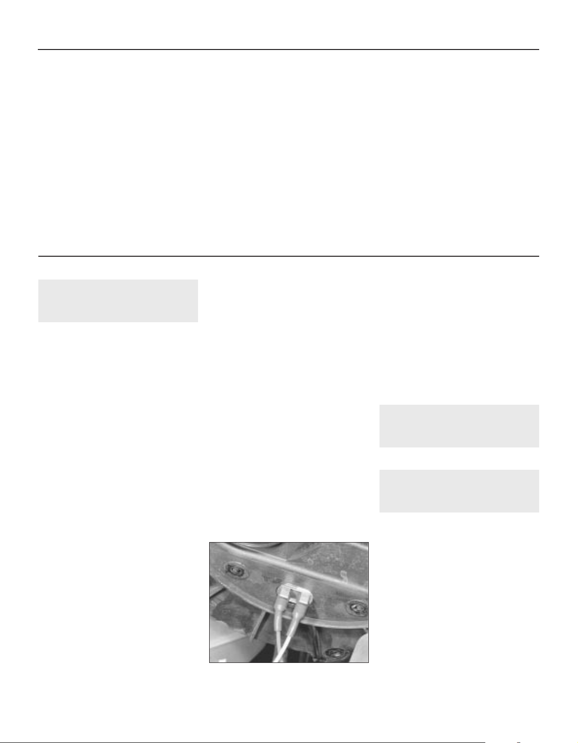
1 General information and
precautions
General information
The fuel system consists of a fuel tank
mounted under the rear of the vehicle, a
mechanical fuel pump and a carburettor. The
fuel pump is operated by an eccentric on the
camshaft and is mounted on the rear of the
cylinder head. The air cleaner contains a
disposable paper filter element and
incorporates a flap valve air temperature
control system which allows cold air from the
outside of the vehicle and warm air from
around the exhaust manifold to enter the air
cleaner in the correct proportions.
The carburettor is the Hobourn SUmanufactured KIF type, a development by
Rover of the previous HIF instrument. To
reduce emissions and to improve driveability
when the engine is cold, the inlet manifold is
heated by the cooling system coolant and by
an electric pre-heater system. Mixture
enrichment for cold starting is by a manuallyoperated choke control.
The exhaust system consists of three
sections which are the front pipe and front
silencer box, the intermediate pipe and
middle silencer box, and the tailpipe and main
silencer box. The system is suspended
throughout its entire length by rubber
mountings. If a catalytic converter is fitted, the
exhaust system consists of four sections, the
catalytic converter being situated between the
front pipe and the (much shorter) intermediate
pipe.
Precautions
Fuel warning
Many of the procedures in this Chapter
require the removal of fuel lines and
connections which may result in some fuel
spillage. Before carrying out any operation on
the fuel system, refer to the precautions given
in Safety first! at the beginning of this Manual
and follow them implicitly. Petrol is a highly
dangerous and volatile liquid and the
precautions necessary when handling it
cannot be overstressed.
Unleaded petrol - usage
The information given in this Chapter is
correct at the time of writing and applies only
to petrol currently available in the UK. If
updated information is required, check with a
Rover dealer. If travelling abroad, consult one
of the motoring organisations (or a similar
authority) for advice on petrol types available
and their suitability for your vehicle
The fuel recommended by Rover for the
214 and 414 models is given in Specifications,
followed by the equivalent petrol currently on
sale in the UK. RON and MON are different
testing standards. RON stands for Research
Octane Number (also written as RM); MON
stands for Motor Octane Number (also written
as MM, which is a different name for the same
octane scale).
All Rover 214 and 414 models are designed
to run on 95 (RON) octane petrol.
Super/Super Plus (unleaded) petrols can be
used without modification. If nothing else is
available, 4-star (leaded) petrol can only be
used if the vehicle is not fitted with a catalytic
converter. The only vehicles which must use
unleaded petrol at all times are those with
catalytic converters.
Catalytic coverters
Before attempting work on these items,
carefully read the precautions listed in Part D
of this Chapter.
2 Air cleaner filter element -
renewal
Refer to Chapter 1.
3 Air cleaner assembly -
removal and refitting
2
Removal
1 Release the two clips securing the air intake
duct to the assembly, then undo the four
screws securing the assembly to its mounting
bracket.
2 Release the assembly from the intake duct
and withdraw it until the thermac switch
vacuum pipes can be reached. Make a note of
the correct fitted positions of the pipes to
ensure that they are correctly connected on
refitting (yellow to the temperature control
valve, red to the inlet manifold) then
disconnect them and withdraw the air cleaner
assembly (see illustration).
3 Check the condition of the O-ring around
the carburettor inlet and renew it if worn or
damaged.
Torque wrench settings Nm lbf ft
Fuel system
Carburettor retaining screws . . . . . . . . . . . . . . . . . . . . . . . . . . . . . . . . . 10 7
Carburettor vent and air bleed pipe mounting nuts and bolts . . . . . . . . 9 7
Needle retaining (grub) screw . . . . . . . . . . . . . . . . . . . . . . . . . . . . . . . . . 1.7 to 2.3 1.3 to 1.7
Throttle disc retaining screws . . . . . . . . . . . . . . . . . . . . . . . . . . . . . . . . . 0.80 to 1.14 0.59 to 0.84
Fuel pump mounting nuts . . . . . . . . . . . . . . . . . . . . . . . . . . . . . . . . . . . . 10 7
Fuel tank hose retaining clip and union nuts . . . . . . . . . . . . . . . . . . . . . 9 7
Manifold temperature sensor . . . . . . . . . . . . . . . . . . . . . . . . . . . . . . . . . 15 11
Inlet manifold nuts and bolts . . . . . . . . . . . . . . . . . . . . . . . . . . . . . . . . . 25 18
Inlet manifold support stay bolts . . . . . . . . . . . . . . . . . . . . . . . . . . . . . . 25 18
Exhaust system
Manifold retaining nuts . . . . . . . . . . . . . . . . . . . . . . . . . . . . . . . . . . . . . . 45 33
Manifold shroud screws . . . . . . . . . . . . . . . . . . . . . . . . . . . . . . . . . . . . . 6 4
System flange nuts:
Manifold-to-front pipe joint . . . . . . . . . . . . . . . . . . . . . . . . . . . . . . . . . 50 37
All other joints . . . . . . . . . . . . . . . . . . . . . . . . . . . . . . . . . . . . . . . . . . . 45 33
Front pipe mounting bolts . . . . . . . . . . . . . . . . . . . . . . . . . . . . . . . . . . . 15 11
4A•2 Fuel and exhaust systems - carburettor engines
3.2 Note colour-coding of thermac switch
vacuum pipes before disconnecting
1689 Rover 214 & 414 Updated Version 09/97
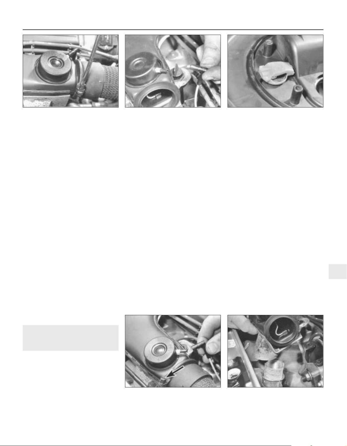
4 To remove the metal intake duct,
disconnect the vacuum pipe from the air
temperature control valve and slacken the
intake hose retaining clamp (see illustration).
Undo the fastener securing the duct to its
mounting bracket and remove the metal duct,
taking care not to lose the hot air intake
connector hose which connects the duct to
the exhaust manifold shroud.
5 To remove the air intake hose, it will first be
necessary to remove the left-hand headlamp
assembly so as to gain access to the two
retaining screws. Remove the retaining
screws securing the front of the hose to the
body front panel then release the clip securing
the ignition HT lead to the hose. If the metal
intake duct is still in position, slacken the hose
clamp then remove the hose from the engine
compartment.
6 A resonator chamber is fitted to the intake
hose to reduce the amount of induction noise.
To remove the chamber, first remove the
battery and battery tray. Disconnect the intake
hose and release any relevant retaining
clips from the resonator then remove the
resonator from the engine compartment.
Refitting
7 Refitting is the reverse of the removal
procedure. Ensure that the vacuum pipes are
correctly reconnected and are not trapped as
the assembly is refitted, then check that the
assembly sits properly on the carburettor inlet
before tightening the screws securely.
4 Air cleaner air temperature
control system - inspection
and component renewal
2
Inspection
1 The system is controlled by a thermac
switch mounted in the air cleaner assembly.
When the engine is started from cold, the
switch is closed to allow inlet manifold
depression to act on the air temperature
control valve in the intake duct. This raises a
vacuum servo in the valve assembly and
draws a flap valve across the cold air intake,
thus allowing only (warmed) air from around
the exhaust manifold to enter the air cleaner.
2 As the temperature of the exhaust-warmed
air in the air cleaner rises, a bi-metallic strip in
the thermac switch deforms and opens the
switch to shut off the depression in the air
temperature control valve assembly. The flap is
lowered gradually across the hot air intake until,
when the engine is fully warmed-up to normal
operating temperature, only cold air from the
front of the vehicle is entering the air cleaner.
3 To check the system, allow the engine to
cool down completely, then slacken the intake
hose retaining clamp and disconnect the hose
from the metal intake duct. The flap valve in
the duct should be securely seated across the
hot air intake. Start the engine. The flap
should immediately rise to close off the cold
air intake and should then lower steadily as
the engine warms up, until it is eventually
seated across the hot air intake again.
4 To check the thermac switch, disconnect
the vacuum pipe from the control valve
when the engine is running and place a finger
over the pipe end (see illustration). When the
engine is cold, full inlet manifold vacuum
should be present in the pipe. When the
engine is at normal operating temperature,
there should be no vacuum in the pipe.
5 To check the air temperature control valve,
slacken the intake hose retaining clamp and
disconnect the hose from the metal intake
duct. The flap valve should be securely seated
across the hot air intake. Disconnect the
vacuum pipe and suck hard at the control
valve stub. The flap should rise to shut off the
cold air intake.
6 If any component is faulty then it must be
renewed.
Thermac switch - renewal
7 Remove the air cleaner assembly.
8 Release the lid retaining clips then remove the
lid and withdraw the air cleaner filter element.
9 Bend up the tags on the switch clip and
remove the clip, then withdraw the switch and
its seal (see illustration).
10 Refitting is the reverse of the removal
procedure. Ensure that the switch mating
surfaces are clean and that the switch and
seal are correctly located before fastening the
clip.
Air temperature control valve renewal
11 Disconnect the vacuum pipe from the air
temperature control valve, then slacken the
intake hose retaining clamp and disconnect
the hose from the metal intake duct (see
illustration).
12 Release the two clips securing the air
intake duct to the air cleaner assembly and
undo the fastener securing the duct to its
mounting bracket. Withdraw the duct, taking
care not to lose the hot air intake connector
hose which connects the duct to the manifold
shroud (see illustration).
Fuel and exhaust systems - carburettor engines 4A•3
4.9 Thermac switch is clipped into air
cleaner assembly
4.4 Disconnect vacuum pipe from control
valve to check operation of system
components
3.4 Slacken clamp to disconnect intake
hose from air cleaner assembly metal
intake duct
4.12 Do not lose hot air intake connector
hose when removing air cleaner metal
intake duct
4.11 Disconnecting vacuum pipe from air
temperature control valve - intake hose-to-
metal intake duct securing clamp
(arrowed)
4A
1689 Rover 214 & 414 Updated Version 09/97
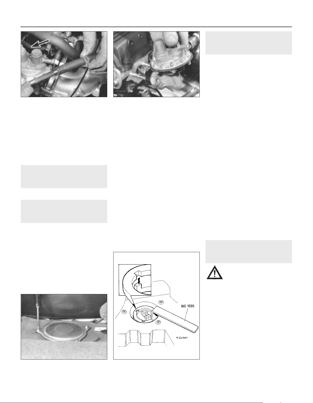
13 The air temperature control valve can be
renewed only with the complete intake duct
assembly. If a new intake duct assembly is
being fitted, undo the four screws securing
the hot air intake adaptor plate to the bottom
of the duct and transfer the adaptor plate to
the new duct.
14 Refitting is the reverse of the removal
procedure.
5 Fuel system - inspection
Refer to Chapter 1.
6 Fuel pump - testing,
removal and refitting
2
Testing
1 To test the fuel pump on the engine,
temporarily disconnect the outlet pipe which
leads to the carburettor and hold a wad of rag
over the pump outlet while an assistant spins
the engine on the starter. Keep your hands
away from the electric cooling fan. Regular
spurts of fuel should be ejected as the engine
turns.
2 The pump can also be tested by removing
it. With the pump outlet pipe disconnected
but the inlet pipe still connected, hold a wad
of rag by the outlet. Operate the pump lever
by hand, moving it in and out. If the pump is in
a satisfactory condition, a strong jet of fuel
should be ejected.
Removal
3 Identify the pump inlet and outlet hoses
then, using a pair of pliers, release the
retaining clips and disconnect them from the
pump. Place wads of rag beneath the hose
unions to catch any spilled fuel and plug the
hose ends to minimise fuel loss (see
illustration).
4 Slacken and remove the nuts and washers
securing the pump to the cylinder head.
5 Withdraw the fuel pump from the engine
and remove the insulating block (see
illustration).
Refitting
6 Refitting is the reverse of the removal
procedure. Clean the mating surfaces and
renew the insulating block if its sealing
surfaces are marked or damaged. Tighten the
pump mounting nuts to the specified torque
wrench setting.
7 Fuel gauge sender unit -
removal and refitting
2
Removal
1 Disconnect the battery negative lead.
2 On 214 models, open the tailgate and
remove the parcel tray shelf. Fold the rear
seats fully forwards then raise the luggage
compartment carpet to gain access to the fuel
sender unit access cover.
3 On 414 models, open the boot lid and lift up
the luggage compartment carpet to gain
access to the fuel sender unit access cover.
4 On all models, undo the three screws and
remove the access cover from the floor (see
illustration).
5 Remove the sender unit wiring connector
rubber cover and disconnect the connector
from the sender.
6 Unscrew the sender unit retaining ring by
turning it in an anti-clockwise direction and
remove it from the fuel tank. In the absence of
the special Rover ring spanner, Service tool
number 18G 1595 (see illustration), a pair of
slip-jointed pliers will serve as an adequate
substitute to slacken the ring.
7 Carefully lift the sender unit, taking great
care not to bend or damage the sender float,
and remove the sealing ring. Examine the
sealing ring and renew it if it is worn or
damaged.
Refitting
8 Refitting is the reverse of the removal
procedure. Ensure that the tab on the sender
unit is correctly engaged with the cutout in the
fuel tank.
8 Fuel tank -
removal and refitting
3
Warning: Do not under any
circumstances attempt to solder
or weld a fuel tank.
Removal
1 Before removing the fuel tank, all fuel must
be drained from the tank. Since a fuel tank
drain plug is not provided, it is therefore
preferable to carry out the removal operation
when the tank is nearly empty. Before
proceeding, disconnect the battery negative
lead and syphon or hand pump the remaining
fuel from the tank.
2 Chock the front wheels, then jack up the
rear of the vehicle and support it on
axle stands. Remove the left-hand rear
roadwheel.
3 Undo the bolt then slacken and remove the
two screws securing the cover fitted to the
left-hand side of the fuel tank. Prise out the
screw retaining plugs and remove the cover to
4A•4 Fuel and exhaust systems - carburettor engines
7.6 Using Rover special tool to remove
fuel gauge sender unit
7.4 Undo three screws to remove fuel
gauge sender unit access cover
6.5 Removing fuel pump and insulating
block
6.3 Plug fuel hoses after disconnection -
pump inlet hose disconnected, outlet hose
arrowed
1689 Rover 214 & 414 Updated Version 09/97

gain access to the fuel tank feed and return
pipes (see illustration).
4 Using a suitable pair of pliers, release the
retaining clip and disconnect the small section
of return pipe hose from the fuel tank (see
illustration).
5 Slacken the fuel feed pipe union nut and
disconnect the pipe from the union. Undo the
two union mounting bolts and free the union
from the body (see illustration).
6 Disconnect the fuel tank wiring block
connector from the main wiring harness. If the
block connector cannot yet be reached, it
may be disconnected as the tank is lowered
out of position.
7 Slacken the clamp securing the filler neck
hose to the tank and use a pair of pliers to
release the filler neck breather pipe retaining
clip (see illustration). Disconnect both the
filler neck hose and breather pipe from the
fuel tank.
8 Release the fuel tank breather, situated
directly above the filler neck hose, from the
vehicle body.
9 Slacken the tank retaining strap locknuts,
then unscrew the lower locknuts and remove
the straps whilst supporting the tank (see
illustration).
10 Lower the fuel tank out of position and
remove it from under the vehicle.
11 If the tank is contaminated with sediment
or water, remove the sender unit and swill the
tank out with clean fuel. If the tank is
damaged or leaks, it should be repaired by a
specialist or alternatively renewed. Do not
under any circumstances attempt to solder or
weld a fuel tank.
Refitting
12 Refitting is the reverse of the removal
procedure. Tighten all nuts and bolts to their
specified torque wrench settings and ensure
that all hoses are correctly routed and
securely fastened so that there can be no risk
of fuel leakage.
9 Accelerator cable - removal,
refitting and adjustment
2
Removal
1 Unscrew the four windscreen wiper motor
mounting bolts to free the motor from the
engine compartment bulkhead.
2 Slacken the accelerator cable locknuts and
free the cable outer from its mounting bracket
on the carburettor. Release the cable inner
from the accelerator cam (see illustration).
3 Work back along the cable outer and
release it from any retaining clamps and ties.
4 Working from inside the vehicle, undo the
five right-hand lower facia panel retaining
screws and remove the panel.
5 Release the cable from the upper end of the
accelerator pedal and withdraw the cable
from the engine compartment.
Refitting
6 Refitting is the reverse of the removal
procedure. Tighten the windscreen wiper
motor retaining bolts to the specified torque
(Chapter 12). Prior to tightening the cable
locknuts, adjust the cable as follows.
Adjustment
7 Slacken both locknuts then gently pull up
on the cable outer until all free play is
removed from the cable and the accelerator
cam just starts to move.
8 Holding the cable in position, screw the
upper locknut down until there is a gap of
approximately 5.0 mm between the lower
edge of the nut and the cable mounting
bracket. Release the cable then have an
assistant depress the accelerator pedal fully
and check that the throttle opens fully and
returns to the at-rest position when the pedal
is released. If the throttle operation is correct,
hold the upper locknut stationary and tighten
the lower locknut securely.
10 Accelerator pedal -
removal and refitting
2
Removal
1 Working from inside the vehicle, undo the
five right-hand lower facia panel retaining
screws and remove the panel.
Fuel and exhaust systems - carburettor engines 4A•5
8.5 Feed pipe union mounting bolts
(arrowed)
8.4 Fuel tank return pipe retaining clip (A)
and feed pipe union nut (B)
9.2 Disconnecting accelerator cable from
carburettor
8.9 Fuel tank mounting strap retaining
locknut
8.7 Slacken filler neck hose retaining
clamp (A) and disconnect breather pipe (B)
8.3 Removing cover retaining bolt
(arrowed) and screw retaining plugs
4A
1689 Rover 214 & 414 Updated Version 09/97

2 Release the accelerator cable from the
upper end of the pedal and, using a pair of
pliers, unhook the accelerator pedal return
spring.
3 Prise off the circlip from the pedal pivot and
withdraw the accelerator pedal from the
mounting bracket.
Refitting
4 Refitting is a reverse of the removal
procedure. Apply a smear of multi-purpose
grease to the pedal pivot. On completion,
adjust the accelerator cable.
11 Accelerator pedal switch -
removal and refitting
2
Removal
1 Working from inside the vehicle, undo the
five right-hand lower facia panel retaining
screws and remove the panel.
2 Using a suitable pair of pliers, unhook the
accelerator pedal return spring from the pedal
then disconnect the accelerator cable from
the pedal.
3 Disconnect the wiring connectors from the
accelerator pedal switch then prise off the Cclip and remove the switch from the mounting
bracket. Note the wave washer fitted between
the switch and bracket.
Refitting
4 Refitting is a reversal of the removal
procedure.
12 Choke cable - removal,
refitting and adjustment
2
Removal
1 Remove the air cleaner assembly.
2 Free the choke cable outer from its
retaining clip on the carburettor and
disconnect the cable inner from the choke
cam (see illustration).
3 Work back along the cable outer and
release it from any retaining clamps and ties.
Prise the cable grommet out of the engine
compartment bulkhead.
4 Working inside the vehicle, undo the five
right-hand lower facia panel retaining screws
and remove the panel.
5 Using a suitable small screwdriver, slacken
and remove the choke knob grub screw then
pull the knob off the cable.
6 Unscrew the choke cable retaining nut then
release the cable from the facia and disconnect
the choke switch wiring connectors. The cable
can then be withdrawn from the engine
compartment and removed from the vehicle.
Refitting
7 Refitting is a reverse of the removal
procedure. On completion adjust as follows.
Adjustment
8 Have an assistant pull the choke control knob
fully out and check that the choke cam
opens fully. Push the choke knob fully in and
check that the choke cam returns to the fully-off
position so that there is clearance between the
cam and the fast idle adjusting screw. Providing
that the choke cam returns fully, there should
be no free play present in the cable.
9 The cable is adjusted by releasing the
carburettor clip and repositioning the cable
outer.
13 Carburettor -
removal and refitting
4
Removal
1 Remove the air cleaner assembly.
2 Slacken the accelerator cable locknuts and
free the cable outer from its mounting bracket
on the carburettor. Release the cable inner
from the accelerator cam.
3 Free the choke cable outer from its retaining
clip on the carburettor and disconnect the
cable inner from the choke cam.
4 Make a note of the correct fitted positions
of the two small bore vacuum pipes, to ensure
they are correctly positioned on refitting, then
disconnect them from the carburettor (see
illustration).
5 Using pliers, release the retaining clip and
disconnect the fuel feed hose from the
carburettor. Place wads of rag around the union
to catch any spilled fuel and plug the hose as
soon as it is disconnected to minimise fuel loss.
6 Make a note of the correct fitted positions
of the breather hoses then, where necessary,
release the retaining clips and disconnect the
three breather hoses from the carburettor.
7 Disconnect the wiring connector from the
carburettor idle bypass solenoid (see
illustration).
8 Unscrew the four Torx screws securing the
carburettor manifold adaptor to the inlet
manifold and remove the carburettor
assembly from the vehicle (see illustrations).
Remove the gasket and discard it, as a new
one must be used on refitting. Plug the inlet
4A•6 Fuel and exhaust systems - carburettor engines
13.8b . . . and remove carburettor
assembly
13.8a Unscrew upper-to-lower inlet
manifold Torx screws . . .
13.7 Note connections before
disconnecting idle bypass solenoid wiring
13.4 Breather hose (A), float chamber vent
and full load air bleed hoses (B), idle
bypass solenoid wiring (C) and fuel pump
outlet hose (D)
12.2 Releasing clip to disconnect choke
cable from carburettor - fast idle adjusting
screw arrowed
1689 Rover 214 & 414 Updated Version 09/97

port with a wad of clean cloth to prevent the
possible entry of foreign matter.
Refitting
9 Refitting is the reverse of the removal
procedure, noting the following:
a) Ensure the carburettor and inlet manifold
sealing faces are clean and flat. Fit a new
gasket and tighten the carburettor
retaining screws to the specified torque.
b) Use the notes made on dismantling to
ensure all hoses are refitted to their
original positions and, where necessary,
are securely held by their retaining clips.
c) Adjust the choke cable and accelerator
cables.
d) Adjust the idle speed and mixture
settings.
14 Carburettor - diagnosis,
overhaul and adjustments
4
Diagnosis
1 The SU carburettor does not usually suffer
from jet blockages and wear is usually only
found between the needle and jet, although it
is worth checking the fit of the piston in the
suction chamber whenever the carburettor is
dismantled. If the idle speed is too high and
cannot be reduced by normal adjustment, it is
worth checking the throttle disc overrun valve
spring (if fitted). If this spring has weakened,
the throttle disc must be renewed.
2 If a carburettor fault is suspected, always
check first the following:
a) That the ignition timing is accurate.
b) That the spark plugs are in good condition
and correctly gapped.
c) That the accelerator and choke cables are
correctly adjusted.
d) That the carburettor piston damper is
topped-up.
e) That the float chamber vent hose and
(especially if the mixture is very rich) the
full load air bleed hose are clear.
f) That the air cleaner filter element is clean.
3 If the engine is running very roughly, check
the compression pressures, bearing in mind
the possibility that one of the hydraulic
tappets might be faulty, thereby producing an
incorrect valve clearance.
4 If careful checking of all of the above
produces no improvement, the carburettor
must be removed for cleaning and overhaul.
Overhaul
5 A complete strip-down of a carburettor is
unlikely to cure a fault which is not
immediately obvious without introducing new
problems. If persistent carburation problems
are encountered, it is recommended that the
advice of a Rover dealer or carburettor
specialist is sought. Most dealers will be able
to provide carburettor re-jetting and servicing
facilities and if necessary, it should be
Fuel and exhaust systems - carburettor engines 4A•7
14.8 SU KIF carburettor assembly
1 Piston damper
2 Suction chamber
3 C-clip
4 Piston
5 Piston spring
6 Needle retaining (grub)
screw
7 Needle spring
8 Needle
9 Needle guide
10 Idle speed screw
11 Spring
12 Idle speed adjusting knob
13 Throttle spindle seal
14 Screw
15 Throttle disc - with
overrun valve
16 Throttle spindle
17 Return spring
18 Fast idle lever
19 Lockwasher
20 Nut
21 Fast idle adjusting screw
22 Choke assembly
23 O-ring
24 Throttle return spring lever
25 Throttle lever
26 O-ring
27 Diaphragm
28 Idle air bypass screw
29 O-ring
30 Full load enrichment device
31 Spring
32 Idle bypass solenoid
33 Float pivot
34 Pivot seal
35 Carburettor body
36 O-ring
37 Jet adjusting screw
38 Fuel strainer
39 Float needle seat
40 Float needle
41 Float
42 Jet bearing
43 Jet bearing nut
44 Jet
45 Bi-metal lever assembly
46 Spring
47 Jet retaining screw
48 O-ring
49 Float chamber cover
4A
1689 Rover 214 & 414 Updated Version 09/97

possible to purchase a reconditioned
carburettor of the relevant type.
6 If it is decided to go ahead and service a
carburettor, check the cost and availability of
spare parts before commencement. Obtain a
carburettor repair kit, which will contain the
necessary gaskets, diaphragms and other
renewable items.
7 When working on carburettors, scrupulous
cleanliness must be observed and care must
be taken not to introduce any foreign matter
into components. Carburettors are delicate
instruments and care should be taken not to
disturb any components unnecessarily.
8 Referring to the relevent exploded view of
the carburettor (see illustration on previous
page), remove each component part whilst
making a note of its fitted position. Make
alignment marks on linkages, etc.
9 Reassemble the carburettor in the reverse
order to dismantling, using new gaskets, Orings, etc. Be careful not to kink any
diaphragms.
Adjustments
Idle speed and mixture
10 Refer to Chapter 1.
Fast idle speed
11 Check the accelerator and choke cables
are correctly adjusted.
12 Warm the engine up to normal operating
temperature and check that the idle speed
and mixture are correctly set.
13 Pull out the choke control to the first
detent position and check that the engine
speed increases to the specified amount.
14 If adjustment is required, screw the fast
idle adjusting screw in or out until the engine
speed is correct.
Fuel level
15 The carburettor fuel level is adjusted by
bending the float arm to alter the float height,
usually measured with the carburettor
inverted. However, since the necessary
information is not provided by the
manufacturer, the vehicle should be taken to a
Rover dealer or SU carburettor specialist if the
fuel level is thought to be incorrect.
Jet adjustment
16 Accurate jet adjustment is not easy for the
inexperienced and can only be carried out
using an exhaust gas analyser. If the jet
adjustment is thought to be incorrect or is to
be checked, owners without the required
equipment and the skill to use it are advised
to have the work carried out by a Rover dealer
or SU carburettor specialist, otherwise
proceed as follows.
17 Warm the engine up to normal operating
temperature and check that the ignition
timing, idle speed and mixture are correctly
set and that the carburettor piston damper is
topped-up, see Chapter 1.
18 Remove the tamperproof cap from the jet
adjusting screw recess at the front left-hand
corner of the carburettor body.
19 Counting the exact number of turns
required to do so, screw the idle air bypass
screw clockwise until it seats lightly, then start
the engine, switch on the headlamps, heated
rear window and heater blower motor (first
speed only) and adjust the idle speed to 700
to 750 rpm.
20 Connect the exhaust gas analyser
following its manufacturer’s instructions.
21 Turning the jet adjusting screw either way
(clockwise to richen the mixture) by half a turn
at a time and waiting for the analyser reading
to respond and stabilise before making a
further alteration, set the mixture to a base CO
level of 5.5 % ± 0.5 %. When the analyser
reading is steady at the correct level, switch
off all electrical loads.
22 Screw the idle air bypass screw anticlockwise by the number of turns previously
noted to return it to its original setting, then
set the true idle mixture to the specified value.
23 Stop the engine when the adjustment is
correct, disconnect the test equipment and fit
a new tamperproof cap to the jet adjusting
screw recess.
Idle bypass system
24 As well as the carburettor idle air bypass
passage and screw, the system incorporates
the solenoid and the accelerator pedal switch.
25 When the accelerator is closed and the
ignition is switched on the solenoid is
energised, its plunger being retracted to open
the bypass passage. This allows air to bypass
the carburettor piston and thus makes the idle
mixture independent of the needle metering.
Screwing in (clockwise) the idle air bypass
screw reduces the amount of air bypassing
the piston and richens the idle mixture.
26 As soon as the accelerator pedal is
depressed, the accelerator pedal switch
opens, the solenoid is de-energised and the
bypass passage is shut off.
27 To check the system, listen closely by the
carburettor while an assistant switches on the
ignition and depresses and releases the
accelerator pedal several times. The solenoid
should be heard to be clicking in and out.
28 If no clicking is heard, remove the air cleaner
assembly and use a meter or similar to check
the solenoid earth and feed, see Chapter 12.
Use a meter to check that the accelerator pedal
switch contacts open and close. If the solenoid
or switch is faulty, then it must be renewed. Note
that if trouble is encountered with an ignition
system fuse blowing repeatedly, and the fault
cannot otherwise be traced, the solenoid may
be at fault.
15 Inlet manifold pre-heater -
operation, removal and
refitting
2
Operation
1 The system incorporates the manifold PTC
(Positive Temperature Coefficient) heater, the
relay and the manifold temperature switch.
2 When the ignition is switched on and the
engine is cold (coolant below 50°C), the relayenergising current flows through the closed
manifold temperature switch contacts, which
then closes the relay contacts and allows
current to flow from the battery to the heater.
This ensures that the inlet manifold is warm
enough, even before the effect of the coolant
heating becomes apparent, to prevent fuel
droplets condensing in the manifold, thus
improving driveability and reducing exhaust
emissions when the engine is cold.
3 As soon as the engine warms up to
temperatures above 50°C, the switch
contacts open and the relay cuts off the
power supply to the manifold heater.
4 If the engine suddenly develops flat spots
when cold, the system may be faulty.
PTC heater
Removal
5 Drain the cooling system.
6 Apply the handbrake then jack up the front
of the vehicle and support it on axle stands.
Access to the PTC heater can then be gained
from underneath the vehicle, via the gap
between the engine and engine compartment
bulkhead.
7 Disconnect the wiring connector from the
heater terminal then extract the heater
retaining circlip. Withdraw the heater from the
underside of the manifold (see illustrations).
4A•8 Fuel and exhaust systems - carburettor engines
15.7b . . . and remove PTC heater from
inlet manifold - manifold removed for
clarity
15.7a Extract circlip . . .
1689 Rover 214 & 414 Updated Version 09/97

Inspect the heater rubber seal for signs of
damage or deterioration and renew if
necessary.
Refitting
8 Refitting is the reverse of the removal
procedure. Ensure that the heater locating
projection is correctly engaged in the manifold
recess. On completion, lower the vehicle to
the ground and refill the cooling system.
Pre-heater temperature switch
Removal
9 The pre-heater temperature switch is fitted
to the underside of the inlet manifold (see
illustration). Either drain the cooling system
or be prepared for some loss of coolant as the
switch is unscrewed.
10 Release the wire retaining clip and
disconnect the wiring connector from the
switch.
11 Unscrew the switch from the manifold and
withdraw it, then plug the opening to prevent
the entry of dirt. If the cooling system has not
been drained, work quickly to minimise
coolant loss.
Refitting
12 Wipe clean the threads of the switch and
of the thermostat housing. If a sealing washer
is fitted, renew it whenever it is disturbed to
prevent leaks. If no sealing washer is fitted,
apply a smear of sealant to the switch
threads.
13 Refit the switch, working quickly if the
cooling system was not drained, and tighten
it. Reconnect the wiring connector.
14 Replenish the cooling system.
Manifold heater relay
15 Refer to Chapter 12.
16 Inlet manifold -
removal and refitting
3
Note: The following procedure describes
removal of the manifold with the carburettor.
Access to some of the components
concerned is much improved if the carburettor
is first removed separately and if this is done,
the following procedure should be amended
as required.
Removal
1 Disconnect the battery negative terminal.
2 Remove the air cleaner assembly.
3 Drain the cooling system.
4 Disconnect the accelerator and choke
cables.
5 Slacken the retaining clamps and
disconnect the coolant hoses from the inlet
manifold.
6 Trace the float chamber vent hose and the
full load air bleed hose from the carburettor
down to their metal pipes then unscrew the
nut and bolts securing the pipes to the
cylinder block/crankcase.
7 Using pliers, release the retaining clip and
disconnect the fuel feed hose from the
carburettor. Place wads of rag around the
union to catch any spilled fuel and plug the
hose as soon as it is disconnected to
minimise fuel loss.
8 Disconnect the vacuum pipe from the
distributor vacuum diaphragm unit and
disconnect the breather hose from the
cylinder head cover.
9 Slacken and remove the brake vacuum
servo unit hose union bolt and disconnect the
hose. Discard the hose union sealing washers
which must be renewed whenever they are
disturbed.
10 Disconnect the idle bypass solenoid
wiring, making notes of the connections so
that they can be correctly reconnected, then
disconnect the wiring from the manifold preheater switch and heater which are situated
on the underside of the manifold.
11 Undo the single bolt which secures each
manifold support stay to the cylinder
block/crankcase and slacken the bolts which
secure the stays to the inlet manifold (see
illustrations).
12 Make a final check that all the necessary
fuel/breather hoses have been disconnected
from the carburettor/manifold then unscrew
the nuts and bolts securing the manifold
to the cylinder head. Manoeuvre the
manifold out of the engine compartment and
discard its gasket.
Refitting
13 Refitting is the reverse of the removal
procedure, noting the following (see
illustrations):
a) Ensure that the manifold and cylinder
Fuel and exhaust systems - carburettor engines 4A•9
16.11b Inlet manifold support stay lower
end bolt (arrowed)
16.11a Inlet manifold support stay upper
end bolt (arrowed)
15.9 Inlet manifold pre-heater temperature
switch location
16.13c Inlet manifold tightening sequence
- K8 engine
16.13b . . . and fit inlet manifold - less
carburettor
16.13a Fit a new manifold gasket . . .
4A
1689 Rover 214 & 414 Updated Version 09/97
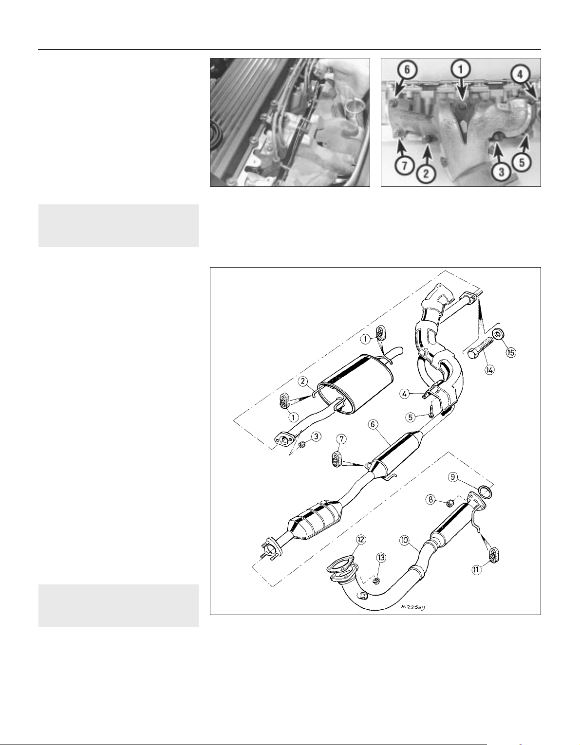
head mating surfaces are clean and dry,
then fit a new manifold gasket.
b) Working in the sequence shown, tighten
the manifold retaining nuts and bolts
evenly to the specified torque wrench
setting.
c) Ensure all relevant hoses are reconnected
to their original positions and are securely
held (where necessary) by their retaining
clips.
d) Renew the vacuum servo unit vacuum
hose banjo union sealing washers and
tighten the union bolt.
e) Adjust the accelerator and choke cables.
f) On completion, refill the cooling system.
17 Exhaust manifold -
removal and refitting
3
Removal
1 Disconnect the battery negative terminal.
2 Remove the air cleaner metal intake duct
assembly.
3 Firmly apply the handbrake then jack up the
front of the vehicle and support it on axle
stands.
4 Unscrew the nuts securing the exhaust
front pipe to the manifold, then disconnect the
pipe and collect the gasket.
5 Remove the four exhaust manifold shroud
retaining screws and remove the shroud.
6 Unscrew the nuts securing the manifold to
the cylinder head, then manoeuvre it out of
the engine compartment. Remove the
manifold gasket and discard it.
7 Examine all the exhaust manifold studs for
signs of damage and corrosion. Remove all
traces of corrosion and repair or renew any
damaged studs.
Refitting
8 Refitting is the reverse of the removal
procedure, noting the following (see
illustrations):
a) Ensure that the manifold and cylinder
head sealing faces are clean and flat, then
fit a new manifold gasket.
b) Working in the sequence shown, tighten
the manifold retaining nuts evenly to the
specified torque wrench setting.
c) Tighten all other disturbed nuts and bolts
to their specified torque wrench settings
(where given).
18 Exhaust system - inspection,
removal and refitting
3
Note: If a catalytic converter is fitted to the
exhaust system, remember that it is FRAGILE.
Do not use hammers, mallets, etc. to strike
any part of the system and take care not to
drop it or strike the converter against anything
while handling it.
1 On models not equipped with a catalytic
converter the exhaust system is in three
sections. All exhaust sections are joined by a
flanged joint. If a catalytic converter is fitted, it
is situated between the front pipe and the
intermediate pipe, with a flanged joint at each
end. The front pipe then has a gas-sampling
take off point which is fitted to permit mixture
checks using an exhaust gas analyser (see
illustrations).
4A•10 Fuel and exhaust systems - carburettor engines
18.1a Exhaust system components - without catalytic converter
1 Mounting rubber
2 Tailpipe
3 Nut
4 Heatshield
5 Bolt
6 Intermediate pipe
7 Mounting rubber
8 Nut
9 Gasket - front pipe to
intermediate pipe
10 Front pipe
11 Mounting rubber
12 Gasket - front pipe to
exhaust manifold
13 Nut
14 Bolt (stud replacement)
15 Plain washer
17.8b Exhaust manifold tightening
sequence - K8 engine
17.8a Refitting exhaust manifold with new
gasket
1689 Rover 214 & 414 Updated Version 09/97
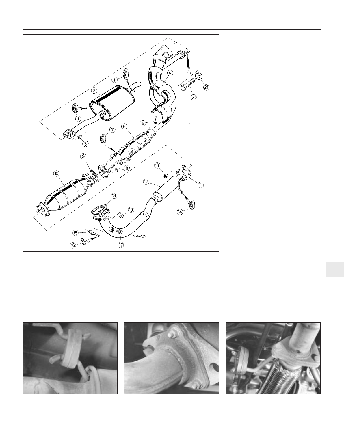
2 The exhaust system is suspended
throughout its entire length by rubber
mountings (see illustration).
Inspection
3 Refer to Chapter 1.
Removal
4 Each exhaust section can be removed
individually or, alternatively, the complete
system can be removed as a unit once the
front pipe has been unbolted from the
manifold and the system has been freed from
all its mounting rubbers.
5 To remove the system or any part of the
system, first jack up the front or rear of the
vehicle and support it on axle stands.
Alternatively position the vehicle over an
inspection pit or on car ramps.
Front pipe
6 Remove the three nuts securing the front
pipe flange joint to the manifold and, where
necessary, the two bolts securing the front
pipe to its mounting bracket. Separate the
flange joint and collect the gasket (see
illustration).
7 Free the pipe from its mounting rubber then
undo the three nuts securing the front pipe to
the intermediate pipe/catalytic converter (as
applicable) and manoeuvre the front pipe out
from under the vehicle (see illustration).
Catalytic converter
8 Slacken and remove the two nuts securing
the catalytic converter to the intermediate
pipe, then separate the flange joint and
recover the gasket.
9 Undo the three nuts securing the converter to
the front pipe then remove it from the vehicle.
Intermediate pipe
10 Slacken the two nuts securing the tailpipe
flange joint to the intermediate pipe and
separate the flange joint.
11 Undo the three nuts securing the
intermediate pipe to the front pipe, or the two
nuts securing the pipe to the catalytic
converter (as applicable).
12 Free the intermediate pipe from all its
mounting rubbers and manoeuvre it out from
under the vehicle.
Fuel and exhaust systems - carburettor engines 4A•11
18.1b Exhaust system components - with catalytic converter
1 Mounting rubber
2 Tailpipe
3 Nut
4 Heatshield
5 Bolt
6 Intermediate pipe
7 Mounting rubber
8 Nut
9 Gasket - catalytic converter
to intermediate pipe
10 Catalytic converter
11 Gasket - front pipe to
catalytic converter
12 Front pipe
13 Nut
14 Mounting rubber
15 Gas sampling pipe - open
loop system
16 Gas sampling pipe sealing
screw - open loop system
17 Blanking plug - closed
loop system
18 Gasket - front pipe to
exhaust manifold
19 Nut
20 Bolt (stud replacement)
21 Plain washer
18.7 Front pipe-to-intermediate pipe
flange joint and mounting rubber
18.6 Front pipe-to-manifold flange joint18.2 Exhaust system rubber mounting
4A
1689 Rover 214 & 414 Updated Version 09/97

Tailpipe
13 Remove the two nuts securing the tailpipe
flange joint to the intermediate pipe and
separate the joint (see illustration).
14 Unhook the tailpipe from its three mounting
rubbers and remove it from the vehicle.
15 If the threads of the intermediate pipe to
tailpipe studs are damaged, or the studs snap
when the nuts are being undone, the studs
can be knocked out of position and replaced
with bolts.
Refitting
16 Each section is refitted by a reverse of the
removal sequence, noting the following:
a) Ensure that all traces of corrosion have
been removed from the flanges.
b) Renew all necessary gaskets.
c) Inspect all rubber mountings for signs of
damage or deterioration and renew as
necessary.
d) Tighten all flange nuts by hand only
to locate the disturbed section in
position, then ensure all exhaust
system rubber mountings are correctly
seated.
e) Check that there is adequate clearance
between the exhaust system and vehicle
underbody before tightening all flange
nuts to the specified torque.
4A•12 Fuel and exhaust systems - carburettor engines
18.13 Tailpipe-to-intermediate flange
joint
1689 Rover 214 & 414 Updated Version 09/97

1689 Rover 214 & 414 Updated Version 09/97
4B
Chapter 4 Part B Fuel and exhaust systems single-point fuel injection engines
Accelerator cable - removal, refitting and adjustment . . . . . . . . . . . 11
Accelerator pedal - removal and refitting . . . . . . . . . . . . . . . . . . . . . 12
Air cleaner assembly - removal and refitting . . . . . . . . . . . . . . . . . . . 3
Air cleaner air temperature control system - inspection and
component renewal . . . . . . . . . . . . . . . . . . . . . . . . . . . . . . . . . . . 4
Air cleaner filter element - renewal . . . . . . . . . . . . . . . . . . . . . . . . . . 2
Exhaust manifold - removal and refitting . . . . . . . . . . . . . . . . . . . . . 18
Exhaust system - inspection, removal and refitting . . . . . . . . . . . . . 19
Fuel gauge sender unit - removal and refitting . . . . . . . . . . . . . . . . . 9
Fuel injection system components - removal and refitting . . . . . . . . 15
Fuel injection system components - testing . . . . . . . . . . . . . . . . . . . 14
Fuel pump - removal and refitting . . . . . . . . . . . . . . . . . . . . . . . . . . . 8
Fuel system - depressurisation . . . . . . . . . . . . . . . . . . . . . . . . . . . . . 6
Fuel system - inspection . . . . . . . . . . . . . . . . . . . . . . . . . . . . . . . . . . 5
Fuel system - pressure check . . . . . . . . . . . . . . . . . . . . . . . . . . . . . . 7
Fuel tank - removal and refitting . . . . . . . . . . . . . . . . . . . . . . . . . . . . 10
General information and precautions . . . . . . . . . . . . . . . . . . . . . . . . 1
Inlet manifold pre-heater - operation, removal and refitting . . . . . . . 16
Inlet manifold - removal and refitting . . . . . . . . . . . . . . . . . . . . . . . . 17
Throttle housing - removal and refitting . . . . . . . . . . . . . . . . . . . . . . 13
4B•1
Contents
Specifications
System
Type . . . . . . . . . . . . . . . . . . . . . . . . . . . . . . . . . . . . . . . . . . . . . . . . . . . . Rover/Motorola Modular Engine Management System, using ECU-
controlled single-point injection (MEMS-SPi) and speed/density
method of airflow measurement
MEMS-SPi system data
Fuel pump type . . . . . . . . . . . . . . . . . . . . . . . . . . . . . . . . . . . . . . . . . . . . Electric, immersed in fuel tank
Fuel pump pressure:
Maximum - at 16 volts . . . . . . . . . . . . . . . . . . . . . . . . . . . . . . . . . . . . 2.7 bar
Regulated constant pressure . . . . . . . . . . . . . . . . . . . . . . . . . . . . . . . 1.0 to 1.2 bar
Injector/pressure regulator assembly . . . . . . . . . . . . . . . . . . . . . . . . . . . JZX 3028
Throttle potentiometer voltage:
Throttle closed . . . . . . . . . . . . . . . . . . . . . . . . . . . . . . . . . . . . . . . . . . 0 to 1 volt
Throttle open . . . . . . . . . . . . . . . . . . . . . . . . . . . . . . . . . . . . . . . . . . . . 4 to 5 volts
Idle speed - nominal value given for reference purposes only . . . . . . . . 850 ± 50 rpm
CO level at idle speed - engine at normal operating temperature:
Without catalytic converter - at tailpipe . . . . . . . . . . . . . . . . . . . . . . . 0.5 to 2.0 %
With catalytic converter - at gas-sampling pipe . . . . . . . . . . . . . . . . . 0.5 to 2.0 %
Recommended fuel
Minimum octane rating:
Without catalytic converter . . . . . . . . . . . . . . . . . . . . . . . . . . . . . . . . . 95 RON unleaded (ie: unleaded Premium) or 97 RON leaded
(ie: 4-star)
With catalytic converter . . . . . . . . . . . . . . . . . . . . . . . . . . . . . . . . . . . 95 RON unleaded (ie: unleaded Premium)
Easy, suitable for
novice with little
experience
Fairly easy, suitable
for beginner with
some experience
Fairly difficult,
suitable for competent
DIY mechanic
Difficult, suitable for
experienced DIY
mechanic
Very difficult,
suitable for expert DIY
or professional
Degrees of difficulty
5
4
3
2
1
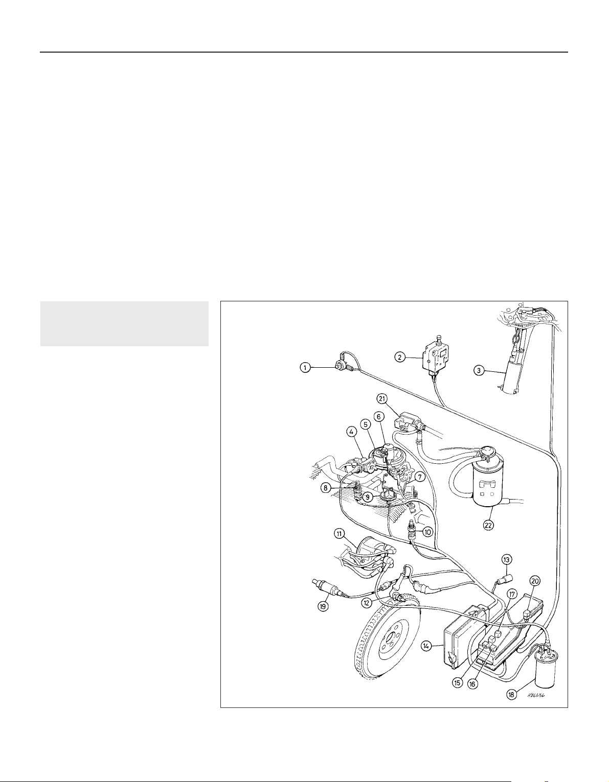
Torque wrench settings Nm lbf ft
Fuel system
Injector housing fuel pipe union nuts . . . . . . . . . . . . . . . . . . . . . . . . . . . 24 18
Injector housing fuel pipe adaptors . . . . . . . . . . . . . . . . . . . . . . . . . . . . 24 18
Injector housing screws . . . . . . . . . . . . . . . . . . . . . . . . . . . . . . . . . . . . . 5 4
Throttle housing retaining nuts . . . . . . . . . . . . . . . . . . . . . . . . . . . . . . . . 18 13
Fuel system pressure release bolt - models without catalytic converter12 9
Fuel pump retaining nuts . . . . . . . . . . . . . . . . . . . . . . . . . . . . . . . . . . . . 9 7
Vent valve and hose retaining nuts . . . . . . . . . . . . . . . . . . . . . . . . . . . . . 9 7
ECU retaining nuts . . . . . . . . . . . . . . . . . . . . . . . . . . . . . . . . . . . . . . . . . 9 7
Intake air temperature sensor . . . . . . . . . . . . . . . . . . . . . . . . . . . . . . . . . 7 5
Coolant temperature sensor . . . . . . . . . . . . . . . . . . . . . . . . . . . . . . . . . . 15 11
Inlet manifold nuts and bolts . . . . . . . . . . . . . . . . . . . . . . . . . . . . . . . . . 25 18
Inlet manifold support stay bolts . . . . . . . . . . . . . . . . . . . . . . . . . . . . . . 25 18
Exhaust system
Oxygen (lambda) sensor . . . . . . . . . . . . . . . . . . . . . . . . . . . . . . . . . . . . . 55 41
Exhaust manifold retaining nuts . . . . . . . . . . . . . . . . . . . . . . . . . . . . . . . 45 33
Exhaust manifold shroud screws . . . . . . . . . . . . . . . . . . . . . . . . . . . . . . 6 4
Exhaust system flange nuts:
Manifold-to-front pipe joint . . . . . . . . . . . . . . . . . . . . . . . . . . . . . . . . . 50 37
All other joints . . . . . . . . . . . . . . . . . . . . . . . . . . . . . . . . . . . . . . . . . . . 45 33
Exhaust front pipe mounting bolts . . . . . . . . . . . . . . . . . . . . . . . . . . . . . 15 11
4B•2 Fuel and exhaust systems - single-point fuel injection engines
1689 Rover 214 & 414 Updated Version 09/97
1 General information and
precautions
General information
The fuel system consists of a fuel tank
mounted under the rear of the vehicle with an
electric fuel pump immersed in it, a fuel filter,
fuel feed and return lines and the throttle body
assembly (which incorporates the single fuel
injector and the fuel pressure regulator), as
well as the Engine Management Electronic
Control Unit (ECU) and the various sensors,
electrical components and related wiring. The
ECU fully controls both the ignition system
and the fuel injection system, integrating the
two in a complete engine management
system (see illustration). Refer to Chapter 5
for information on the ignition side of the
system.
The Rover/Motorola Modular Engine
Management System uses ECU-controlled
single-point injection (MEMS-SPi) and the
speed/density method of airflow
measurement. The whole system is best
explained if considered as three sub-systems
which are, the fuel delivery, air metering and
electrical control systems.
The fuel delivery system incorporates the
fuel tank with an electric fuel pump, which is
immersed in a swirl pot to prevent aeration of
the fuel, inside it. When the ignition is
switched on, the pump is supplied with
current via the fuel pump relay, under the
control of the ECU. The pump feeds petrol via
a non-return valve (to prevent fuel draining out
of the system components and back to the
tank when the pump is not working) to the fuel
filter and from the filter to the injector. Fuel
pressure is controlled by the pressure
regulator, which lifts to allow excess fuel to
1.0 Fuel and ignition system components - MEMS-SPi
1 Accelerator pedal
switch
2 Fuel cut-out inertia
switch
3 Fuel pump
4 Throttle
potentiometer
5 Fuel pressure
regulator
6 Injector
7 Stepper motor
8 Intake air temperature
sensor
9 Inlet manifold PTC
heater
10 Coolant
temperature
sensor
11 Distributor
12 Crankshaft sensor
13 Diagnostic connector
14 Engine management
ECU
15 Main relay
16 Fuel pump relay
17 Inlet manifold PTC
heater relay
18 Ignition HT coil
19 Lambda sensor -
models
equipped with
catalytic
converter
20 Lambda sensor relay -
models equipped with
catalytic converter
21 Purge valve (where
fitted)
22 Charcoal canister
(where fitted)
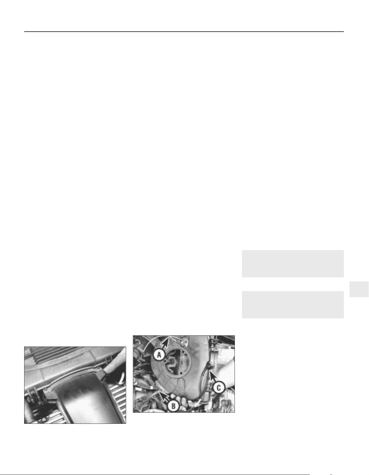
return to the tank swirl pot, where a venturi
causes the returning fuel to draw cool fuel
from the tank into the swirl pot. In the event of
sudden deceleration (ie: an accident) an
inertia switch cuts off the power to the pump
so that the risk of fire is minimised from fuel
spraying out of broken fuel lines under
pressure.
The air metering system includes the intake
air temperature control system and the air
cleaner, but the main components are in the
throttle body assembly. This incorporates the
injector, which sprays fuel onto the back of
the throttle disc, the throttle potentiometer,
which is linked to the throttle disc spindle and
sends the ECU information on the rate of
throttle opening by transmitting a varying
voltage, and the stepper motor, which is
controlled by the ECU and operates the
throttle disc spindle lever via a cam and
pushrod to provide idle speed control. Note
that there is no provision for adjustment of the
idle speed except by reprogramming the ECU
using Rover diagnostic equipment. If checking
idle speed, remember that it will vary
constantly under ECU control.
The electrical control system consists of the
ECU, with all the sensors that provide it with
information, and the actuators by which it
controls the whole system’s operation. The
ECU’s manifold absolute pressure sensor is
connected, by hoses and a fuel (vapour) trap
mounted in the air cleaner assembly, to the
inlet manifold. Variations in manifold pressure
are converted into graduated electrical signals
which are used by the ECU to determine the
load on the engine. The intake air temperature
sensor is self-explanatory, the crankshaft sensor gives it the engine speed and
crankshaft position, the coolant temperature
sensor gives it the engine temperature and the
accelerator pedal switch tells it when
the accelerator is closed. The throttle
potentiometer is explained above and the
lambda sensor (where fitted) in Part D of this
Chapter. In addition, the ECU senses battery
voltage (adjusting the injector pulse width to
suit and using the stepper motor to increase
the idle speed and, therefore, the alternator
output if it is too low), incorporates shortcircuit protection and diagnostic capabilities
and can both receive and transmit information
via the diagnostic connector, thus permitting
engine diagnosis and tuning by Rover
diagnostic equipment. If either the coolant
temperature sensor, the intake air
temperature sensor or the manifold absolute
pressure sensor circuits should fail to provide
adequate information, the ECU has a back-up
facility which assumes a value corresponding
to a coolant temperature of 60ºC, an intake air
temperature of 35ºC and an engine load
based on the engine speed and throttle
position. These are used to implement a
back-up air/fuel mixture ratio.
All these signals are compared by the ECU,
using digital techniques, with set values preprogrammed (mapped) into its memory.
Based on this information, the ECU selects
the response appropriate to those values and
controls the ignition HT coil (varying the
ignition timing as required), the fuel injector
(varying its pulse width - the length of time the
injector is held open - to provide a richer or
weaker mixture, as appropriate), the stepper
motor (controlling the idle and fast idle
speeds), the fuel pump relay (controlling the
fuel delivery), the manifold heater relay
(controlling the inlet manifold pre-heater
system) and the main relay, the purge control
valve (where fitted) and the lambda sensor
and relay (where fitted) accordingly. The
mixture, idle speed and ignition timing are
constantly varied by the ECU to provide the
best settings for cranking, starting and engine
warm-up (with either a hot or cold engine),
idle, cruising and acceleration. A rev-limiter
circuit is built into the ECU which switches off
the injector earth (ie: the fuel supply) if engine
speed exceeds 6860 rpm, switching it back
on at 6820 rpm. The injector earth is also
switched off on the overrun (coolant
temperature above 80ºC, throttle pedal switch
contacts closed, engine speed above
1500 rpm) to improve fuel economy and
reduce exhaust emissions.
The ECU idle control is an adaptive system
which learns the engine load and wear
characteristics over a period of time and
adjusts the idle speed to suit. If the ECU is
renewed, or one from another vehicle is fitted,
it will take a short period of normal driving for
the new ECU to learn the engine’s
characteristics and restore full idle control.
To reduce emissions and to improve
driveability when the engine is cold, the inlet
manifold is heated by the cooling system
coolant and by an electric pre-heater system.
Mixture enrichment for cold starting is a preprogrammed function of the system.
The air cleaner contains a disposable paper
filter element and incorporates a flap valve air
temperature control system which allows
cold air from the outside of the vehicle and
warm air from the exhaust manifold to enter
the air cleaner in the correct proportions.
The exhaust system is as described in Part
A of this Chapter.
Precautions
Fuel injection system
Residual pressure will remain in the fuel
lines long after the vehicle was last used,
therefore extra care must be taken when
disconnecting a fuel line hose. Loosen any
fuel hose slowly to avoid a sudden release of
pressure which may cause fuel spray. As an
added precaution, place a rag over each
union as it is disconnected to catch any fuel
which is forcibly expelled.
Fuel usage
Refer to Part A of this Chapter.
Catalytic converters
Before attempting work on these items,
carefully read the precautions listed in Part D
of this Chapter.
2 Air cleaner filter element -
renewal
Refer to Chapter 1.
3 Air cleaner assembly -
removal and refitting
2
Removal
1 Release the two clips securing the air intake
duct to the assembly, then undo the three
screws securing the assembly to the throttle
body (see illustration).
2 Release the assembly from the intake duct
and withdraw it, collecting the throttle housing
seal and the intake duct sealing ring (where
fitted), then disconnect the following (see
illustration):
a) The thermac switch vacuum pipes. These
are colour-coded (yellow to the
temperature control valve, red to the inlet
manifold).
b) The ECU manifold absolute pressure
sensor fuel trap vacuum hoses. These are
colour-coded (green to the ECU, white to
the inlet manifold).
c) The intake air temperature sensor wiring.
Fuel and exhaust systems - single-point fuel injection engines 4B•3
3.2 Thermac switch vacuum pipes (A), fuel
trap vacuum hoses (B), intake air
temperature sensor wiring (C) and throttle
housing seal (D)
3.1 Releasing clips to separate intake duct
from air cleaner
4B
1689 Rover 214 & 414 Updated Version 09/97

3 Check the condition of the throttle housing
seal and the intake duct O-ring (where fitted).
Renew either if worn or damaged.
4 To remove the metal intake duct, refer to
Section 4, paragraphs 3 and 4.
5 To remove the air intake hose it will first be
necessary to remove the left-hand headlamp
assembly, to gain access to the two retaining
screws. Remove the two retaining screws and
disconnect the duct from the body front
panel, release the clip securing the ignition HT
lead, then slacken the retaining clamp and
unfasten the rubber strap to separate the cold
air duct from the intake duct. Release the
intake hose from the resonator T-piece and
remove it from the engine compartment.
6 A resonator chamber is fitted to the intake
hose to reduce the amount of induction noise.
To remove the chamber, first remove the
battery and battery tray. Disconnect the intake
hose from the T-piece then remove the
resonator T-piece. Release any relevant
retaining clips from the resonator, then
remove the resonator from the engine
compartment (see illustrations).
Refitting
7 Refitting is the reverse of the removal
procedure. Ensure that the vacuum pipes and
hoses are correctly reconnected and are not
trapped as the assembly is refitted, then
check that the assembly sits properly on the
throttle body before tightening the screws
securely.
4 Air cleaner air temperature
control system - inspection
and component renewal
2
Inspection
1 Refer to Section 4 in Part A of this Chapter.
Thermac switch - renewal
2 Refer to Section 4 in Part A of this Chapter,
removing the air cleaner assembly as
described in the previous Section.
Air temperature control valve renewal
3 Disconnect the vacuum pipe from the air
temperature control valve, then slacken the
intake hose retaining clamp. Release the
intake hose rubber retaining strap and
disconnect the hose from the metal intake
duct (see illustration).
4 Release the two clips securing the air intake
duct to the air cleaner assembly and undo the
bolt securing the duct to its mounting bracket
(see illustration). Withdraw the duct, taking
care not to lose the hot air intake connector
hose which connects the duct to the exhaust
manifold shroud.
5 The air temperature control valve can be
renewed only with the complete intake duct
assembly. If a new intake duct assembly is
being fitted, undo the three screws securing
the hot air intake adaptor plate to the bottom
of the duct and transfer the adaptor plate to
the new duct.
6 Refitting is the reverse of the removal
procedure.
5 Fuel system - inspection
Refer to Chapter 1.
6 Fuel system -
depressurisation
2
Warning: The following
procedure will merely relieve the
pressure in the fuel system.
Remember that fuel will still be
present in the system components and
take precautions accordingly before
disconnecting any of them.
1 The fuel system referred to in this Section is
defined as the tank-mounted fuel pump, the
fuel filter, the fuel injector and the pressure
regulator in the injector housing, and the
metal pipes and flexible hoses of the fuel lines
between these components. All these contain
fuel which will be under pressure while the
engine is running and/or while the ignition is
switched on. The pressure will remain for
some time after the ignition has been
switched off and must be relieved before any
of these components are disturbed for
servicing work.
Models with a catalytic
converter
2 On models equipped with a catalytic
converter, the system is depressurised via the
small bolt fitted to the fuel filter inlet (feed)
union nut.
3 Position wads of rag around the union to
catch the spilled fuel and slowly slacken the
bolt.
4 Once all pressure has been released,
remove the bolt. Inspect the sealing washer
for signs of wear or damage and renew if
necessary.
5 Refit the bolt and sealing washer to the
union nut and tighten it securely.
Models without a catalytic
converter
6 On models not fitted with a catalytic
converter, the system is depressurised via the
bolt in the metal fuel filter outlet pipe.
7 Position wads of rag around the pipe to
catch the spilled fuel as the bolt is removed.
Carefully slacken the bolt whilst holding the
fuel pipe boss with an open-ended spanner to
4B•4 Fuel and exhaust systems - single-point fuel injection engines
4.4 Unfastening intake duct-to-support
bracket retaining bolt
4.3 Unfastening cold air intake duct
rubber strap - vacuum pipe (A) and clamp
screw (B)
3.6b . . . then remove resonator3.6a Remove T-piece . . .
1689 Rover 214 & 414 Updated Version 09/97
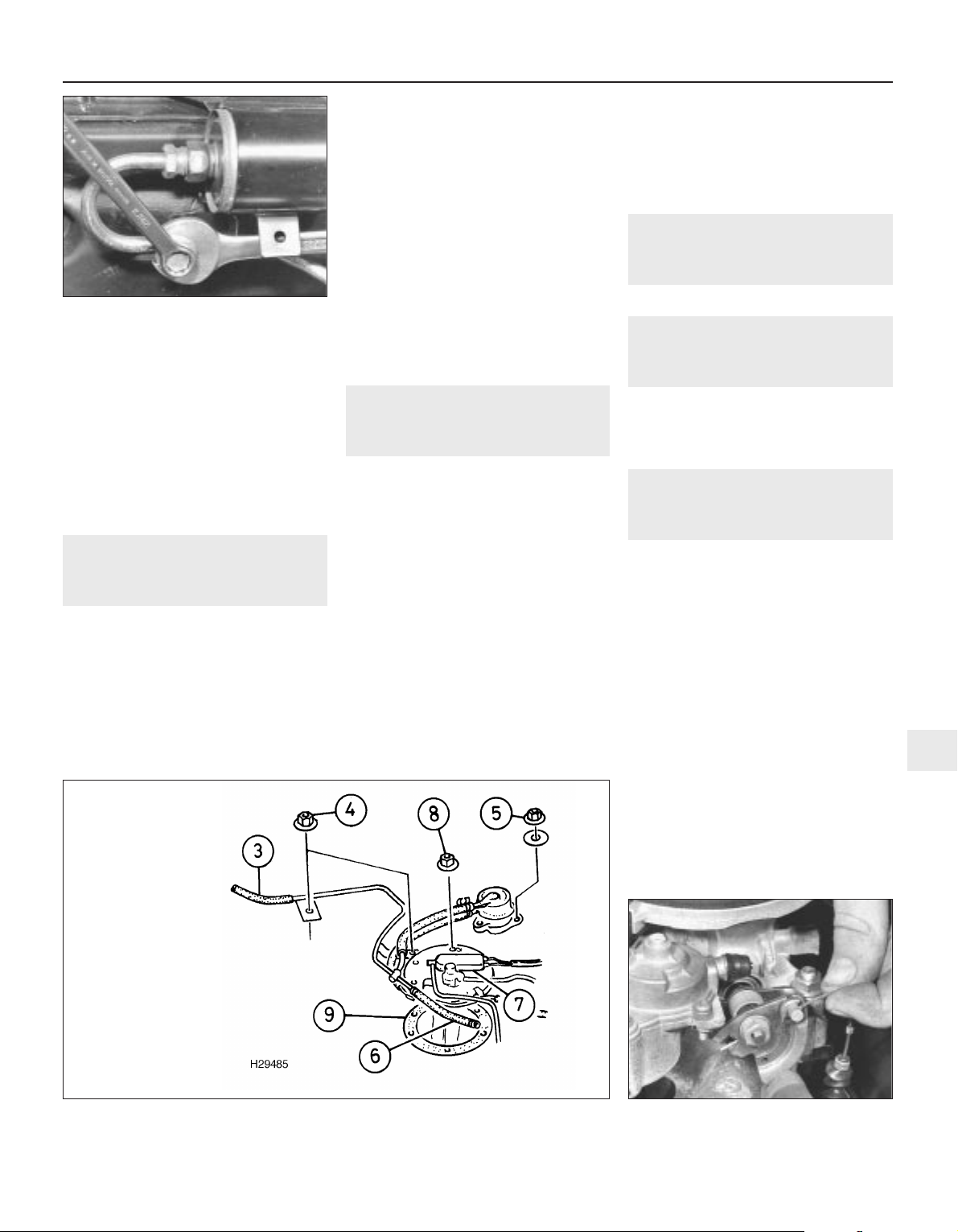
prevent any undue strain being placed on the
fuel pipe (see illustration).
8 Once all pressure has been relieved,
remove the bolt and inspect the sealing
washer for signs of wear or damage and
renew if necessary.
9 Refit the bolt and washer to the fuel pipe
and tighten it to the specified torque wrench
setting whilst using a spanner to counter-hold
the pipe boss, to prevent the pipe or filter
being damaged.
7 Fuel system - pressure check
1 The following procedure is based on the
use of the Rover pressure gauge and adaptor
(Service tool numbers 18G 1500 and
18G 1500/3).
2 Depressurise the fuel system.
3 Unscrew the pressure release bolt and
screw in the adaptor, then connect the
pressure gauge.
4 Turn the engine over on the starter motor.
The pressure should reach the specified
value. Stop cranking the engine and watch the
gauge. The pressure drop in the first minute
should not exceed 0.7 bar.
5 If the pressure first recorded was too high,
renew the pressure regulator, which means
renewing the complete injector housing
assembly.
6 If the pressure first recorded was too low or
if it falls too quickly, check the system
carefully for leaks. If no leaks are found, check
the pump by substituting a new one, then
recheck the pressure. If the pressure does not
improve, the fault is in the pressure regulator
and the complete injector housing assembly
must be renewed. If this is the case, it is worth
dismantling the regulator to check that the
fault is not due to its being jammed open with
dirt.
8 Fuel pump -
removal and refitting
3
Removal
1 Remove the fuel tank.
2 Release the clips securing the tank vent
hose to the fuel tank breather and fuel cut-off
valve, then disconnect the hose. Undo the
vent hose and valve retaining nuts, then
disconnect the vent valve hose from the fuel
pump and remove the vent hose and valve
assembly from the tank (see illustration).
3 Disconnect the wiring connector from the
fuel pump.
4 Slacken and remove the six fuel pump
retaining nuts. Carefully withdraw the fuel
pump assembly from the tank and remove
the pump seal.
Refitting
5 Refitting is a reversal of the removal
sequence, noting the following:
a) Renew the pump seal if there is any doubt
as to its condition.
b) Tighten all retaining nuts to the specified
torque setting.
c) Ensure that the vent hoses are correctly
connected and are securely held by any
necessary retaining clips.
9 Fuel gauge sender unit -
removal and refitting
Refer to Section 7 in Part A of this Chapter.
10 Fuel tank -
removal and refitting
1 Refer to Section 8 in Part A of this Chapter.
Note that the fuel system must be
depressurised before any fuel hose is
disconnected.
11 Accelerator cable - removal,
refitting and adjustment
2
Removal
1 Remove the four windscreen wiper motor
mounting bolts to free the motor from the
engine compartment bulkhead.
2 Slacken the accelerator cable locknuts and
free the cable outer from its mounting bracket.
Release the cable inner from the throttle cam
(see illustration).
3 Work back along the cable outer and
release it from any retaining clamps.
4 Working inside the vehicle, undo the five
right-hand lower facia panel retaining screws
and remove the panel.
5 Release the cable from the upper end of the
accelerator pedal and withdraw the cable
from the engine compartment.
Refitting
6 Refitting is the reverse of the removal
procedure. Tighten the windscreen wiper
motor retaining bolts to the specified torque
Fuel and exhaust systems - single-point fuel injection engines 4B•5
6.7 Slackening pressure release bolt to
depressurise fuel system - non-catalyst
system
11.2 Disconnecting accelerator cable from
throttle cam pulley
8.2 Fuel pump connections
4B
1689 Rover 214 & 414 Updated Version 09/97
3 Tank vent hose
4 Vent pipe nuts
5 Vent valve nut
6 Cut-off valve hose
7 Pump multiplug
8 Pump housing nuts
9 Pump housing seal

(Chapter 12) and prior to tightening the cable
locknuts, adjust the cable as follows.
Adjustment
7 With the pedal fully released, check that
there is equal clearance on each side of the
throttle lever at the lost motion link (see
illustration) and no slack in the cable. Have
an assistant fully depress the pedal and check
that the throttle cam opens fully, then check
that it returns to the at-rest position when
released.
8 To adjust the cable, switch on the ignition
and position the stepper motor by moving the
cam only to open, and fully close the throttle.
Note that it is essential for accurate
positioning of the stepper motor that the
accelerator pedal switch contacts remain
closed, so that the ECU recognises the
throttle movement as a command and
indexes the stepper motor to 25 steps.
9 Slacken the adjuster locknut (upper nut),
then tighten the adjuster (lower) nut until the
clearance is equal on each side of the throttle
lever at the lost motion link. Tighten the
locknut without disturbing this setting.
Recheck the adjustment and switch off the
ignition.
12 Accelerator pedal -
removal and refitting
Refer to Section 10 in Part A of this Chapter.
13 Throttle housing -
removal and refitting
2
Removal
1 Depressurise the fuel system.
2 Disconnect the battery negative terminal
and remove the air cleaner assembly.
3 Examine the injector housing fuel pipe feed
and return unions for signs of leakage, then
wipe them clean.
4 Using a spanner to hold each adaptor,
unscrew the pipe union nuts and release the
fuel feed and return pipes from the adaptors.
Plug each pipe and adaptor to minimise the
loss of fuel and prevent the entry of dirt into
the system.
5 Release the wire retaining clips then
disconnect the wiring connectors from the
injector housing, the throttle potentiometer
and the stepper motor.
6 Slacken the accelerator cable locknuts and
free the cable outer from its mounting bracket.
Release the cable inner from the throttle cam.
7 Using a suitable pair of pliers, release the
retaining clips and disconnect the breather
hoses from the throttle housing (see
illustration).
8 Slacken and remove the four nuts securing
the throttle housing to the inlet manifold, then
remove the throttle housing from the vehicle.
Remove the throttle housing insulating spacer
and examine it for signs of wear or damage,
renewing it if necessary (see illustrations).
9 If leakage was detected from the feed and
return pipes or their union nuts, check the
sealing surfaces of the nuts and adaptors and
renew the adaptor or the pipe assembly, as
necessary.
10 If leakage is detected from the adaptors,
unscrew each through one turn with a
spanner, then through two turns by hand. If
the adaptor is still a tight fit in the housing, the
threads are damaged and the housing and
adaptors must be renewed as a set. If the
threads are sound, fit new sealing washers to
the adaptors and refit them, tightening them
to their specified torque wrench setting.
Refitting
11 Refitting is a reverse of the removal
sequence, noting the following:
a) Ensure that the mating surfaces of the
throttle housing and inlet manifold are
clean then fit the insulating spacer.
b) Tighten the throttle housing and fuel pipe
union nuts to their specified torque
settings.
c) On completion, reconnect and adjust the
accelerator cable.
14 Fuel injection system
components - testing
5
1 If a fault appears in the engine management
(ignition/fuel injection) system, first ensure
that the fault is not due to poor maintenance.
That is, check that the air cleaner filter
element is clean, the spark plugs are in good
condition and correctly gapped, and that the
engine breather hoses are clear and
undamaged. Also check that the throttle cable
is correctly adjusted. If the engine is running
very roughly, check its compression
pressures, bearing in mind that possibly one
of the hydraulic tappets might be faulty,
producing an incorrect valve clearance.
2 If these checks fail to reveal the cause of
the problem, the vehicle should be taken to a
suitably-equipped Rover dealer for testing. A
wiring block connector is incorporated in the
engine management circuit into which a
special electronic diagnostic tester can be
plugged. The tester will locate the fault quickly
and simply, thereby alleviating the need to
test all the system components individually
4B•6 Fuel and exhaust systems - single-point fuel injection engines
13.8b . . . and remove throttle body gasket
spacer
13.8a Lift throttle body assembly away
from inlet manifold . . .
13.7 Disconnecting breather hoses from
throttle housing
1689 Rover 214 & 414 Updated Version 09/97
11.7 Accelerator cable adjustment
1 Throttle lever to lost motion link clearance
should be equal on each side
2 Adjuster nut
3 Adjuster locknut
 Loading...