

627
OWNER’S HANDBOOK
Publication Part No. LRL 18 02 53 701

About this handbook
This handbook forms part of the Owner literature supplied with your new vehicle.
The Quick start section is designed to rapidly familiarise the driver with the initial set up and also
explain some of the unique features. Please take the time to study the operating instructions with
your vehicle as soon as you can.
Important
The information contained in this handbook covers all vehicle derivatives and optional equipment.
Some of the options may not be fitted to your vehicle unless they formed part of the original vehicle
specification. Therefore some parts of this handbook may not apply to your vehicle. Furthermore,
due to printing cycles, it may include descriptions of options before they become generally
available.
The information contained in this publication was correct when it went to print. Vehicle design
changes may have been made after this handbook was printed. When this occurs a handbook
supplement is added to the literature pack. Subsequent updates can be viewed on the Land Rover
Internet site at; www.ownerinfo.landrover.com.
In the interest of development, the right is reserved to change specifications, design or equipment
at any time without notice and without incurring any obligations. This publication, or part thereof,
may not be reproduced nor translated without our approval. Errors and omissions excepted.
© Land Rover 2006
All rights reserved.
Published by Land Rover Technical Communications.
2

Contents
Quick start
QUICK START ................................................... 7
Gas station information
GAS STATION INFORMATION......................... 35
Introduction
SYMBOLS GLOSSARY .................................... 37
LABEL LOCATIONS ......................................... 37
HEALTH AND SAFETY..................................... 38
DATA RECORDING.......................................... 39
PARTS AND ACCESSORIES............................ 39
CALIFORNIA PROPOSITION 65
WARNING ....................................................... 40
REPORTING SAFETY DEFECTS
(U.S. ONLY) .................................................... 41
REPORTING SAFETY DEFECTS
(CANADA ONLY) ............................................. 41
Keys and remote controls
PRINCIPLE OF OPERATION ............................ 42
GENERAL INFORMATION ON RADIO
FREQUENCIES ................................................ 43
USING THE KEY .............................................. 43
PROGRAMMING THE REMOTE CONTROL...... 44
Locks
LOCKING AND UNLOCKING............................ 46
Seat belts
GENERAL INFORMATION ............................... 62
SEAT BELT REMINDER .................................. 64
FASTENING THE SEAT BELTS ........................ 64
SEAT BELT HEIGHT ADJUSTMENT ................ 65
USING SEAT BELTS DURING PREGNANCY.... 65
Supplementary restraint systems
PRINCIPLE OF OPERATION ............................ 66
SIDE AIR BAGS .............................................. 69
CURTAIN AIR BAGS ....................................... 69
OCCUPANT DETECTION ................................. 69
PASSENGER AIR BAG STATUS INDICATOR... 70
AIR BAG WARNING LAMP ............................. 71
AIR BAG WARNING LABELS .......................... 71
AIR BAG SERVICE INFORMATION.................. 72
Child safety
CHILD SEATS ................................................. 73
LATCH ANCHOR POINTS................................ 75
CHILD SAFETY LOCKS ................................... 77
Steering wheel
ADJUSTING THE STEERING WHEEL .............. 78
HORN ............................................................. 78
AUDIO CONTROL ........................................... 78
VOICE RECOGNITION ..................................... 79
CRUISE CONTROL.......................................... 79
Engine immobiliser
PRINCIPLE OF OPERATION ............................ 48
CODED KEYS .................................................. 48
Alarm
PRINCIPLE OF OPERATION ............................ 49
ARMING THE ALARM ..................................... 49
SWITCHING OFF THE ALARM ......................... 50
PANIC ALARM ................................................ 50
Seats
SITTING IN THE CORRECT POSITION ............ 51
ELECTRIC SEATS ............................................ 52
HEAD RESTRAINTS ........................................ 54
REAR SEATS................................................... 55
HEATED SEATS............................................... 61
Lighting
GENERAL INFORMATION ............................... 80
LIGHTING CONTROL ...................................... 81
FRONT FOG LAMPS........................................ 82
REAR FOG LAMPS.......................................... 82
HAZARD WARNING FLASHERS...................... 83
ADAPTIVE FRONT LIGHTING SYSTEM (AFS). 83
DIRECTION/TURN INDICATORS..................... 85
INTERIOR LAMPS .......................................... 86
REMOVING A HEADLAMP .............................. 87
REMOVING A REAR LAMP ............................. 88
CHANGING A BULB ........................................ 89
BULB SPECIFICATION CHART ........................ 98
3

Contents
Wipers and washers
WINDSHIELD WIPERS ................................... 99
RAIN SENSOR .............................................. 100
WINDSHIELD WASHERS .............................. 100
REAR WINDOW WIPER AND WASHERS...... 101
ADJUSTING THE WINDSHIELD WASHER
JETS ............................................................. 102
HEADLAMP WASHERS................................. 102
CHECKING THE WIPER BLADES .................. 102
CHANGING THE WIPER BLADES.................. 103
Windows and mirrors
ELECTRIC WINDOWS ................................... 104
ELECTRIC EXTERIOR MIRRORS .................. 105
INTERIOR MIRROR ...................................... 107
Information displays
TRIP COMPUTER ......................................... 108
PERSONALISED SETTINGS.......................... 109
INFORMATION MESSAGES .......................... 110
Climate control
AIR VENTS ................................................... 112
AUTOMATIC CLIMATE CONTROL ................. 114
REAR PASSENGER CLIMATE CONTROLS.... 117
HEATED WINDOWS AND MIRRORS ............ 117
ELECTRIC SUNROOF .................................... 118
Convenience features
SUN VISORS ................................................ 120
SUN BLINDS................................................. 120
INSTRUMENT LIGHTING DIMMER ............... 120
CLOCK .......................................................... 121
CIGAR LIGHTER ........................................... 122
ASHTRAY ..................................................... 122
AUXILIARY POWER SOCKETS ..................... 123
CUP HOLDERS ............................................. 124
CENTRE CONSOLE ....................................... 125
COOL BOX .................................................... 126
STORAGE COMPARTMENTS ........................ 127
MEMORY FUNCTION .................................... 128
GARAGE DOOR TRANSCEIVER .................... 129
Starting the engine
GENERAL INFORMATION.............................. 133
STARTER SWITCH ........................................ 133
STEERING WHEEL LOCK .............................. 134
STARTING THE ENGINE ................................ 134
Transmission
AUTOMATIC TRANSMISSION ....................... 135
TRANSFER GEARBOX ................................... 141
Brakes
PRINCIPLE OF OPERATION .......................... 145
HINTS ON DRIVING WITH ABS..................... 147
ELECTRIC PARKING BRAKE (EPB) ............... 148
Parking aid
PRINCIPLE OF OPERATION .......................... 152
USING THE PARKING AID ............................. 152
Driving hints
BREAKING-IN................................................ 154
GENERAL DRIVING POINTS.......................... 154
REDUCED ENGINE PERFORMANCE .............. 156
ECONOMICAL DRIVING ................................ 156
Cruise control
PRINCIPLE OF OPERATION .......................... 157
USING CRUISE CONTROL............................. 157
Stability control
PRINCIPLE OF OPERATION .......................... 159
USING STABILITY CONTROL ........................ 159
Traction control
PRINCIPLE OF OPERATION .......................... 161
Hill descent control (HDC)
PRINCIPLE OF OPERATION .......................... 162
USING HDC ................................................... 162
Terrain response
PRINCIPLE OF OPERATION .......................... 165
USING TERRAIN RESPONSE ........................ 165
4

Contents
Air suspension
PRINCIPLE OF OPERATION .......................... 171
ADJUSTING THE SUSPENSION .................... 172
AIR SUSPENSION MESSAGES ..................... 176
Fuel and refuelling
SAFETY PRECAUTIONS ................................ 178
TYPE OF FUEL............................................... 178
RUNNING OUT OF FUEL ............................... 180
FUEL FILLER FLAP........................................ 180
REFUELLING................................................. 181
FUEL CUT-OFF .............................................. 182
CATALYTIC CONVERTER .............................. 182
Load carrying
GENERAL INFORMATION ............................. 183
LUGGAGE ANCHOR POINTS ......................... 183
REAR LOADSPACE HATCHES....................... 183
LUGGAGE COVERS ....................................... 184
Towing
TOWING A TRAILER ..................................... 187
GEAR CHANGING.......................................... 188
LEVELLING ................................................... 188
ESSENTIAL TOWING CHECKS ...................... 189
RECOMMENDED TOWING WEIGHTS ........... 189
DETACHABLE TOW BALL ............................. 190
TRAILER HITCH ............................................ 193
Vehicle care
CLEANING THE EXTERIOR ........................... 194
CLEANING THE INTERIOR ............................ 195
REPAIRING MINOR PAINT DAMAGE ............ 196
Vehicle battery
BATTERY WARNING SYMBOLS ................... 209
BATTERY CARE ............................................ 209
USING BOOSTER CABLES ............................ 210
CHARGING THE VEHICLE BATTERY............. 212
CHANGING THE VEHICLE BATTERY............. 213
Wheels and tires
GENERAL INFORMATION ............................. 214
CHANGING A ROAD WHEEL ......................... 216
TIRE CARE.................................................... 225
TIRE INFORMATION LABELS ....................... 230
UNIFORM TIRE QUALITY GRADING ............. 233
TIRE PRESSURE MONITORING SYSTEM..... 234
USING SNOW CHAINS ................................. 238
TIRE GLOSSARY .......................................... 239
Fuses
FUSE BOX LOCATIONS................................. 240
CHANGING A FUSE....................................... 241
FUSE SPECIFICATION CHART ...................... 243
Vehicle recovery
TOWING POINTS .......................................... 248
LASHING POINTS ......................................... 249
TRANSPORTING THE VEHICLE .................... 250
TOWING THE VEHICLE ON FOUR WHEELS.. 250
Vehicle identification
VEHICLE IDENTIFICATION NUMBER (VIN)... 252
Technical specifications
TECHNICAL SPECIFICATIONS ...................... 253
Maintenance
GENERAL INFORMATION ............................. 197
OPENING AND CLOSING THE HOOD ............ 199
ENGINE COMPARTMENT OVERVIEW ........... 200
UNDER HOOD COVERS ................................ 202
ENGINE OIL CHECK ...................................... 202
ENGINE COOLANT CHECK ............................ 204
BRAKE FLUID CHECK ................................... 205
POWER STEERING FLUID CHECK ................ 207
WASHER FLUID CHECK ................................ 208
Audio introduction
RADIO RECEPTION....................................... 257
Audio unit overview
AUDIO UNIT OVERVIEW............................... 258
5

Contents
Audio unit operation
ON/OFF CONTROL ........................................ 259
VOLUME CONTROL ...................................... 259
BASS/TREBLE CONTROL ............................. 262
BALANCE/FADE CONTROL ........................... 265
STATION PRESET BUTTONS ........................ 265
WAVEBAND BUTTON ................................... 266
AUTOSTORE CONTROL ................................ 266
RADIO BROADCAST DATA SYSTEM (RBDS) 267
PTY PROGRAMME TYPES............................ 268
Compact disc player
LOADING COMPACT DISCS ......................... 270
EJECTING SINGLE COMPACT DISC ............. 271
EJECTING MULTIPLE COMPACT DISCS....... 272
COMPACT DISC SELECTION ........................ 273
COMPACT DISC PLAYBACK ......................... 273
TRACK SELECTION....................................... 274
COMPACT DISC PAUSE................................ 274
FAST FORWARD/REVERSE .......................... 274
COMPACT DISC FUNCTION MENU ............... 275
SHUFFLE/RANDOM ...................................... 275
REPEAT COMPACT DISC TRACKS ............... 276
COMPACT DISC TRACK SCANNING ............. 276
MP3 FILE PLAYBACK ................................... 277
Rear passenger controls
REAR SEAT CONTROLS ............................... 278
HEADPHONES .............................................. 279
Auxiliary input (AUX IN) socket
AUXILIARY INPUT (AUX IN) SOCKET........... 280
Satellite radio
SATELLITE DIGITAL RADIO.......................... 282
SATELLITE RADIO CONTROLS..................... 283
SATELLITE RADIO SUBSCRIPTION.............. 284
SATELLITE RADIO DISPLAY ........................ 284
RECEIVING SATELLITE RADIO
BROADCASTS .............................................. 286
SATELLITE RADIO MENU FUNCTIONS......... 291
Voice recognition
PRINCIPLE OF OPERATION .......................... 296
USING THE SYSTEM .................................... 296
AUDIO UNIT COMMANDS ............................ 298
6
Quick start
Quick start
QUICK START
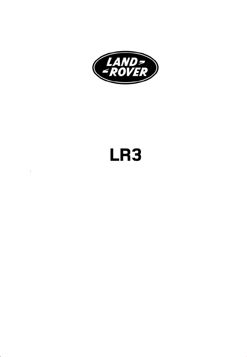
Remote control
Dependent upon specification and vehicle
configuration, the operation of the remote
control may differ from the following.
LAN0604
Press once to lock all doors and arm
the alarm.
Press once to deactivate the alarm
and unlock the driver’s door (Single
point entry).
A second press will unlock all other doors.
Customer configurable button. Can
be programmed to remotely operate
one of the following functions:
• Headlamp on (default).
• Panic alarm.
• Air suspension.
See PROGRAMMING THE REMOTE CONTROL
(page 44).
Single point entry
This is a security feature that unlocks only the
driver’s door. It can be disabled on individual
remote controls by simultaneously pressing
and holding the lock and unlock buttons for
three seconds. The vehicle will lock and then
unlock in the currently selected mode to
confirm the change.
You can now unlock all doors with a single
press. Repeating the procedure will re-enable
Single point entry.
Automatic relock
If the vehicle is unlocked with the remote
control, it will automatically relock and arm the
alarm if a door or the tailgate is not opened
within one minute.
Key blade
Press button (arrowed in illustration) to release
the key blade.
Remote control battery
The remote control battery is rechargeable and
should never need replacement. The battery is
recharged whenever the key is in the starter
switch and the engine running.
7
Quick start
Central locking
1
2
LAN0605
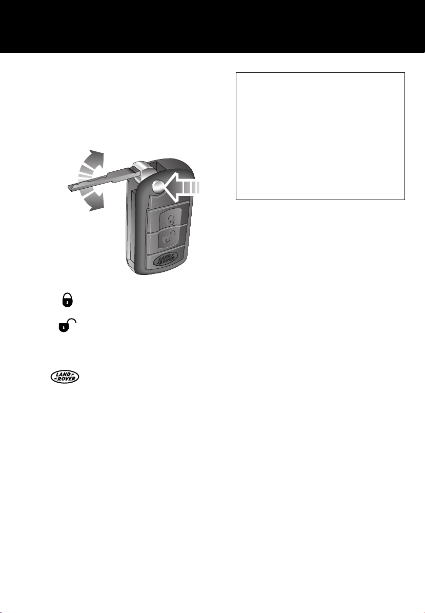
Master lock and unlock switches
1. Press to unlock all doors and tailgate.
2. Press to lock all doors and tailgate.
Speed-related locking
If enabled, the doors and tailgate will
automatically lock when the vehicle's speed
exceeds 8 km/h (5 mph).
This feature can be disabled or enabled in the
Settings option accessed via the trip computer.
Tailgate
1
2
LAN0606
Opening the upper tailgate
With all the doors unlocked, press the release
switch 1 on the underside of the exterior handle
and pull to open.
Opening the lower tailgate
With the upper tailgate open, press the touch
pad 2 on the lower tailgate waist moulding.
Operating note
If the tailgate is locked/unlocked 10 times
within a short period, the latch will be
disabled for approximately one minute, to
protect the battery and lock mechanism.
8

Quick start
Hood
Driver's seat adjustment
The position of the seat can be adjusted when
the starter key is in position I or II. In addition,
the seats have a 15 minute (10 minutes for a
driver's seat with seat memory) active period
1
initiated when:
• the driver’s door is opened or closed, or
• the starter key is turned to position 0.
3
3
21
2
LAN0607
Opening
Pull the hood release lever 1 located on the
left-hand side of the vehicle.
Lift the hood safety catch lever 2, located on
the front edge of the hood beneath the centre
point of the words LAND ROVER, and raise the
hood.
Closing
Lower the hood until the safety catch engages.
Using both hands, press the hood down until
the catches click.
Check that both catches 3 are engaged by
trying to lift the front edge of the hood.
LAN0698N
1. Seat forward/backward, cushion height
and front tilt control switch.
2. Backrest adjustment switch.
3. Lower backrest lumbar support control.
9

Quick start
L
Driving position memory (when fitted)
Once you have adjusted the power operated
driver's seat and exterior mirrors for your ideal
driving position, the vehicle can memorise
these settings for future use.
12
AN0699G
1. Press the memory store button 1 to
activate the memory function for five
seconds.
2. Press one of the preset buttons 2 within
five seconds to memorise the current
settings.
Memory Stored will be displayed on the
message centre accompanied by an
audible chime to confirm the settings have
been memorised.
Lazy entry
When this feature is enabled, the vehicle stores
the seating and mirror positions for each
remote control. Next time the vehicle is
unlocked using a remote control, the position
of the seat and mirrors will adjust to the last
used position.
This feature can be disabled or enabled in the
Settings option accessed via the trip computer.
Steering column adjustment
Operating note
A seat position will only be memorised during
the five second active period.
Any existing settings will be over-written
when programming a memory position.
LAN0615
1. Move the lever located under the steering
wheel fully downward.
2. Adjust the height and reach of the steering
wheel to the desired position.
3. Move the lever fully up to lock the position
of the wheel.
10

Quick start
Windows and Door mirrors
1
2
LAN0700N
• To open a window, press and hold the
respective switch.
• To close the window, pull and hold the
switch.
• Window movement can be stopped at any
time by releasing the switch.
The front windows have a one touch facility
that allows them to be fully opened or closed
with a single operation of the switch. Firmly
press or lift the switch and release. Movement
can be stopped by briefly operating the switch
again.
Press the right-hand side of switch 2 to inhibit
the operation of the rear window switches.
Resonance with lowered windows
If a resonance/booming sound occurs when a
rear window is open, lowering an adjacent
front window about 25 mm (1 inch) will
eliminate the condition.
Door mirror adjustment
To adjust the mirrors, rotate the mirror
adjustment knob 1 left or right to select the
appropriate mirror. Move the knob in any
direction to adjust the position of the mirror
glass.
Reverse automatic mirror dip (when fitted)
With the feature enabled, when reverse gear is
selected the door mirrors will dip.
The dip position of the door mirrors can be
personalised as follows.
1. Turn the starter switch to position I or II.
Do not start the engine.
2. Select/store a driver’s seat memory
position. See ELECTRIC SEATS (page 52).
3. Select reverse gear, the door mirrors will
adjust to a preset position.
4. Adjust the mirrors to the required dipped
position.
5. Perform a memory store procedure on the
currently selected driver’s seat position.
DOOR MIRROR DIP STORED will be
displayed on the message centre
accompanied by a single chime.
This feature can be disabled or enabled in the
Settings option accessed via the trip computer.
See TRIP COMPUTER (page 108).
11
Quick start
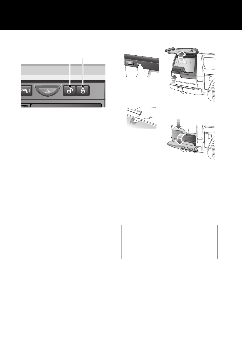
Overhead console
2
LAN0702N
Courtesy lamps
If automatic mode is enabled, the front and rear
courtesy lamps will operate in conjunction with
the vehicle being unlocked/locked or when a
door is opened.
The courtesy lamps can be manually switched
on/off by pressing and releasing the centre
lamp switch (arrowed in illustration).
Automatic mode
Automatic mode for the courtesy lamps can
be enabled/disabled by pressing and holding
the centre lamp switch for more than three
seconds.
A message will be displayed in the message
centre advising you of the currently set
mode.
1
Sunroof
To open the sunroof:
• Press and release the rear of the switch 1
to open the roof to the tilt position.
• Press and release the rear of the switch
again to open the roof fully.
To close the sunroof:
• Press and release the front of the switch 2
to close the roof to the tilt position.
• Press and hold the front of the switch
again to close the roof fully.
If the sunroof is moving, it can be stopped by
pressing the switch again.
Operating note
The sunroof can be operated with the starter
key in position I or II and for 40 seconds after
position 0 has been selected, providing that
neither front door has been opened.
With the starter key in position I or 0, the
switch will need to be pressed and held until
the roof reaches the desired position.
Interior lamps
The interior lamps can be switched on/off by
pressing the switch adjacent to the lamp.
12
Quick start
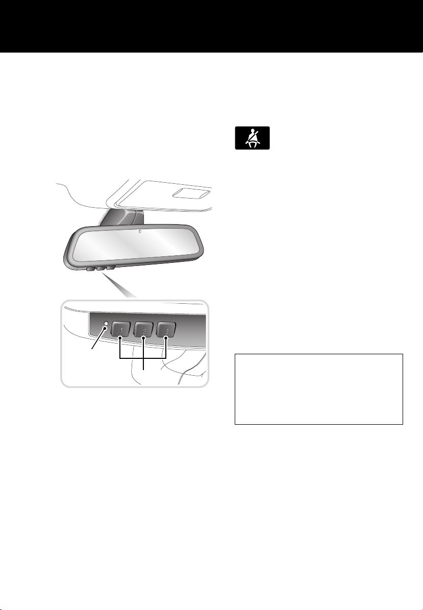
Rear view mirror
Some rear view mirrors are fitted with a feature
that will automatically darken to counteract
glare from the headlamps of a following
vehicle.
This feature is temporarily switched off when
reverse gear is selected.
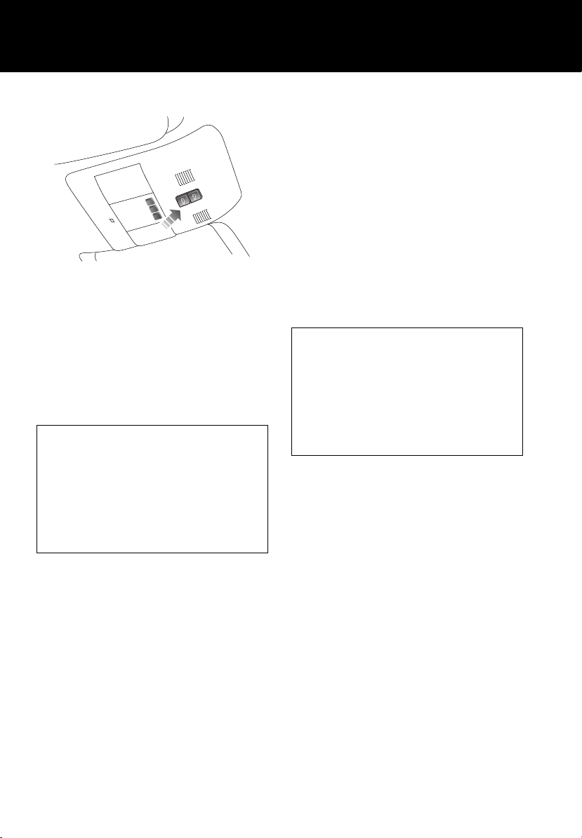
Homelink® transmitter
1
2
E83587
1. Status indicator (Red = transmitting)
2. Channel buttons
The buttons 2 can be programmed to transmit
radio frequencies that can operate external
devices, i.e. garage doors, entry gates, security
systems.
For more information, refer to See GARAGE
DOOR TRANSCEIVER (page 129).
Seat belts and child restraints
The use of front and rear seat belts is
mandatory in most countries. Using seat belts
saves lives. They should be worn by all
occupants whenever the vehicle is in use.
A warning light on the instrument
pack will illuminate to alert you that
the driver's and/or front
passenger's seat belt is unbuckled. Dependent
upon specification this may be accompanied by
an intermittent chime.
Automatic locking reels (ALR)
All passenger seat belts have ALR fitted for use
with child seats or securing large items.
• To engage: extend belt to maximum length
to enable locking mechanism.
• Allow seat belt to retract onto the child
seat/item (a clicking sound will be heard as
the belt retracts). Ensure there is no slack
by pressing the seat/item firmly into the
vehicle seat.
• To disengage: unbuckle belt and allow belt
to fully retract.
With ALR enabled, as the seat belt retracts, it
will automatically lock preventing
re-extension.
Ensure passengers do not fully extend the
restraints and inadvertently engage this
feature during normal use.
13

Quick start
Child Seats
It is important to remember that the child's
weight, rather than age, determines the type of
seat that is required. See CHILD SEATS
(page 73).
Recommended child seat
Land Rover strongly recommends the use of
LATCH (Lower Anchors and Tethers for
CHildren) child seats.
LATCH child seats can only be fitted in the
second-row outer seating positions.
Passenger airbag deactivation
PASS
AIRBAG
OFF
PASS
AIR BAG
OFF
LAN0703N
The front passenger seat is fitted with an
occupancy sensor system that determines the
state of seat occupancy and sets the airbag
status to suit.
• Seat unoccupied - airbag deactivated and
indicator off.
• Seat occupied - airbag activated and
indicator off.
• Seat occupied by child seat or low weight
object - airbag deactivated and indicator
on.
Operating note
If the indicator becomes permanently
illuminated when the seat is empty, please
contact your Land Rover Dealer immediately.
14

Quick start
Heating and ventilation
These are the primary functions of the heating
and ventilation system. Dependent upon
specification, the control panel may differ from
those shown.
1 1
LAN0618
2
Air conditioning
Air conditioning is an integral part of the
heating and ventilation system, providing
cooled and dehumidified air for occupant
comfort. The dry airflow is effective in
preventing misting of windows and is also
beneficial at low external temperatures.
Air conditioning is automatically switched on
and controlled whenever the system is not
operating in economy mode.
External water deposits
The air conditioning system removes
moisture from the air and deposits excess
water beneath the vehicle. Puddles may form,
but this is normal and no cause for concern.
AUTO mode
Press AUTO to select automatic
operation of the system, both LEDs
in the switch will illuminate.
The system will adjust the heat output, blower
speed, air intake and airflow distribution to
maintain the selected temperature(s) and
reduce misting without further adjustments.
The air distribution and blower controls can be
operated to override the automatic settings.
This will extinguish the appropriate LED in the
AUTO control.
Recommended mode
Select AUTO as the normal operating mode.
This will help prevent window misting and
odours from the climate control system.
15

Quick start
Temperature selection
Rotate the controls 1 to adjust the temperature
for the respective side of the passenger
compartment.
Operating note
On the automatic system, it is not possible to
achieve a temperature differential of more
than 4°C (7°F) between the left and right.
Blower speed
Rotate the blower control 2 to adjust airflow
through the vents. As the control is adjusted,
LEDs will illuminate to indicate which of the
eight possible speeds is currently selected.
Air distribution control
Press to select the desired distribution setting.
An LED will illuminate in the switch.
Windshield and side window vents
Face level vents
Foot level vents
More than one setting can be selected to
achieve the desired distribution.
OFF
Press to switch the system off. An
LED will illuminate in the switch to
show this condition.
Press again to return the system to its previous
operating mode. The system will also be
reactivated by using the AUTO, blower speed,
air distribution or defrost controls.
Defrost mode
Press to remove frost or heavy
misting from the windshield. The
system will automatically adjust the
blower output for maximum clearing, in
addition the rear window and windshield
heaters will be activated.
Press again to switch off defrost mode. The
rear screen and windshield heaters will remain
on.
Air recirculation
Press once to activate air
recirculation. An LED will illuminate
in the switch.
Press again to return to fresh air intake.
Economy mode
Press button to put the system into
economy mode. An LED will
illuminate in the switch to show this
condition.
In economy mode air conditioning is switched
off. This reduces the load on the engine,
thereby improving fuel consumption.
Heated windshield (when fitted)
Press to operate. An LED in the
switch will illuminate whilst
operating.
The heater will automatically switch off after a
preset interval.
Heated rear window
Press to operate. An LED in the
switch will illuminate whilst
operating.
The heater will automatically switch off after a
preset interval.
16

Quick start
Seat heaters
Press the relevant button to operate
the required seat heater at high
level. Both LEDs will illuminate.
Press a second time to heat the seat at a lower
level. One LED will extinguish.
Press a third time to switch off.
Rear environment
Press once to activate automatic
mode in which the comfort level for
the rear passengers is controlled
from the front. The upper LED will be
illuminated.
Press a second time to pass control of the rear
environment to the rear passengers control
panel. The lower LED will be illuminated.
Press a third time to switch this feature off.
Neither LED will be illuminated.
Exterior lamps master switch
4
3
2
1
O
T
U
A
A
B
LAN0642
1. Exterior lamps off
2. Sidelamps
3. Headlamps
4. Autolamps
In AUTO mode and the starter switch in
position II, a sensor monitors the exterior light
levels and will automatically switch the side
lamps and dipped headlamps on and off as
required.
A. Front fog lamps (if fitted)
B. Rear fog lamps
If front fog lamps are not fitted, the rear fog
lamps will come on at position A.
Operating note
Fog lamps can not be operated if the lamps
master switch is in AUTO.
17

Facia
Quick start
22 19
LAN0704N
21
20
18
17
CD 3 14 : 54
2Tr 15:43
123456
10 11
6CD-465
6 7 8 95421 3
123
ABC DEF
456
JKL MNOGHI
789
TUV WXYZPQRS
0
12
13
14
15
16
18

Quick start
1. Direction/turn indicators/headlamps/trip
computer switch
2. Cruise control switches
3. Instrument pack/warning indicators and
message centre
4. Audio/telephone switches
5. Wiper/washer switch
6. Audio unit
7. Dynamic stability control (DSC) switch
8. Touch screen
9. Hazard warning switch
10. Master locking switches
11. Passenger airbag status indicator
12. Heater/air conditioning controls
13. Gear selector
14. Terrain response control switch
15. Transfer gearbox switch
16. Hill Descent Control switch
17. Air suspension control
18. Electric Parking Brake (EPB)
19. Starter switch
20. Steering column adjustment
21. Hood release lever
22. Exterior lamps master switch
19
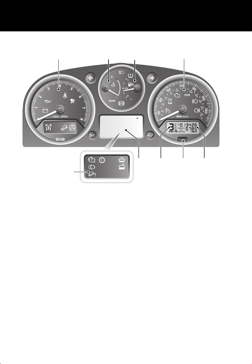
Instrument pack
1 2 3 4
9
LAN0709N
1. Tachometer
2. Temperature gauge
3. Fuel gauge
4. Speedometer
5. Total distance (odometer) and trip
recorder
Quick start
EXT C
23
6. Trip recorder reset switch
7. Gear selector position display
8. Main message centre.
9. Warning indicators panel.
5678
20

Quick start
Tachometer
Indicates engine speed in revolutions per
minute (x 1 000). In normal driving conditions
the engine is most fuel efficient between 2 000
and 3 000 rev/min.
Temperature gauge
At normal operating temperature, the pointer is
positioned midway between the red and blue
segments of the gauge (the precise position
will vary according to climatic conditions).
E80509
If the pointer moves above the mid point, the
engine coolant is becoming too hot. Should the
pointer move into the red segment and the red
warning indicator (arrowed) illuminates,
severe engine damage could occur (under
these circumstances the air conditioning may
switch off and engine performance may reduce
to minimise engine load).
Stop the vehicle as soon as safety permits, and
allow the engine to idle until the warning
indicator extinguishes and the pointer moves
back to its normal position. If the problem
persists, seek qualified assistance
immediately.
Fuel gauge
CAUTION
Never allow vehicles to run out of fuel as
the resultant misfire may destroy the
catalytic converter.
When the starter switch is turned to position II,
the pointer quickly rises to show the level of
fuel in the tank.
E80510
When the remaining fuel reaches a minimum of
12 litres (3 gallons), the amber low fuel
warning indicator (arrowed) illuminates.
The remaining fuel should give a range of
80 km (50 miles).
The small arrow alongside the fuel pump
symbol indicates the side of the vehicle on
which the fuel filler is located.
Total distance (odometer) and trip recorder
Indicates the total distance travelled, and also
shows the most recent individual journey
distance.
Trip recorder reset switch
With the starter switch in position II, press to
reset the trip recorder back to zero.
Selected gear display
The currently selected gear is displayed.
21

Quick start
Warning indicators (attention)
If any of the following illuminates whilst driving
a fault has been detected.
Battery charge indicator.
See page 154.
Low oil pressure.
See page 154.
Electric parking brake - USA.
E83011
See page 148.
Electric parking brake - Canada.
See page 148.
Brake systems - USA.
E83012
See page 145.
Brake systems - Canada.
See page 145.
Anti-lock Braking System.
See page 147.
Airbag system.
See page 71.
Engine management system.
See page 156.
Engine.
See page 156.
Suspension system.
See page 171.
Transmission.
See page 135.
Transmission temperature.
See page 135.
Hill Descent Control (HDC).
See page 162.
Low engine coolant level.
See page 204.
Dynamic Stability Control (DSC).
See page 159.
Adaptive front lighting system.
See page 83.
Tire Pressure Monitoring system.
See page 234.
Warning indicators (information)
The following will illuminate during normal
driving to indicate that a particular system or
feature is operating.
Seat belt reminder.
See page 64.
Door open.
See page 46.
Low screen washer level.
See page 208.
Low gear range selected.
See page 141.
Hill Descent Control (HDC) active.
See page 162.
Cruise control active.
See page 157.
Direction/turn indicator.
See page 85.
Headlamp high beam on.
See page 81.
Sidelamps on.
See page 81.
Rear fog lamps on.
See page 82.
Front fog lamps on.
See page 82.
22

Quick start
Steering column levers
5
3
2
1
0
4
A
LAN0637
Windshield wiper
1. Intermittent wipe or rain sensor operation
2. Normal speed operation
3. High speed operation
4. Single wipe - press and release to operate.
5. Rotate collar to adjust speed of
intermittent wipe or sensitivity of the rain
sensor
Windshield washer
Press and hold the button to operate the
windshield washer and wipers.
B
Intermittent wipe Rain sensor
Short delay Most sensitive to
rain.
Long delay Least sensitive to
rain.
Press and release the button on the
end of the lever to operate the
windshield washer.
Rear wiper and washer
Pull the lever to position A for intermittent
operation of the rear wiper. Pull and hold the
lever in position B to operate the rear washer
and wiper.
Direction/turn indicators/Headlamp high
beam
LAN0640
Move the lever up or down to
activate the direction/turn
indicators.
Moving the lever up or down against spring
pressure and then releasing will flash the
indicators three times. Useful for lane
changing.
Push the lever away from you to
select headlamp high beam. A
warning indicator will illuminate on
the instrument panel.
Trip computer
Press the button on the end of the
lever to cycle through the trip
computer functions displayed on
the message centre.
23
Quick start
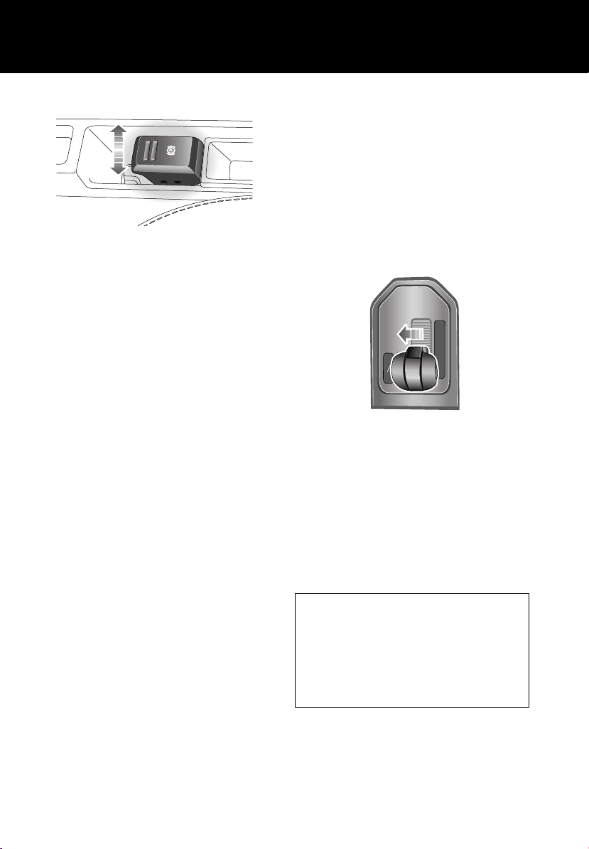
Electric Parking Brake (EPB)
LAN0705N
Applying
With the vehicle stationary, pull up the parking
brake lever and then release it. The red warning
indicator in the instrument panel will
illuminate.
Releasing
The starter switch must be in position I or II.
Apply the foot brake and press down on the
parking brake lever.
If the vehicle is stationary with the parking
brake applied and either D (Drive) or R
(Reverse) selected, pressing the accelerator
will automatically release the parking brake.
Automatic transmission
Gearshift interlock
The starter switch must be in position II, the
foot brake applied and the selector release
button pressed before the gear selector can be
moved from P (Park) to R (Reverse).
The gear selector must be in the P position
before the starter key can be removed.
Sport mode
P
R
+
M
S
-
LAN0644
In SPORT mode, automatic gear changing is
maintained but the gearshift changes are
modified to improve performance.
To select Sport mode, move the gear selector
from the D position towards the left hand side
of the vehicle.
The word SPORT will appear on the instrument
pack display and the LED in the gear selector
surround will illuminate.
N
D
When Sport is selected, the transmission will
stay in lower gears for longer with downshifts
occurring more readily.
Fuel consumption will be adversely affected.
If Terrain Response is fitted, Sport mode is
only available when the General program is
selected.
24

Quick start
CommandShift ™
CommandShift gear selection can be used as
an alternative to automatic gear selection and
is particularly effective when rapid acceleration
or engine braking are required.
P
R
N
D
LAN0645
M
+
S
M
S
-
1. Select Sport mode. The transmission will
automatically select the gear most
appropriate to the vehicle’s road speed and
accelerator position.
2. Moving the selector lever forward (+) or
backward (-) and then releasing will
manually select a higher or lower gear
(when available). The message
TRANSMISSION COMMANDSHIFT
SELECTED will appear in the message
centre.
3. Subsequent gear selections will display the
selected gear on the instrument pack
display.
4. To deselect CommandShift mode, move
the selector lever back to the D position.
Transfer gearbox
LAN0646
HIGH range should be used for all
normal road driving and also for
off-road driving across dry level
terrain.
LOW range should be used in
situations where low speed
manoeuvring is necessary, or in
extreme off-road conditions.
Range changing
The recommended method for range changing
is with the vehicle stationary. With the engine
running, and the main gearbox in N (Neutral),
move the transfer gearbox lever to the required
position and then release. The indicators on the
switch and instrument pack display will flash
during range changing. When range changing
is complete a chime will sound and a message
will be displayed on the message centre.
25

Quick start
Hill Descent Control (HDC)
LAN0649
HDC operates in conjunction with the anti-lock
braking system to provide greater control in
off-road situations particularly when
descending severe gradients.
Press the switch (arrowed in
illustration) to select HDC. HDC can
be selected at speeds below
80 km/h (50 mph) but will not be fully active
until the vehicle speed reduces below 50 km/h
(30 mph), confirmed by a continuously
illuminated HDC indicator in the instrument
pack. Press the switch again to deselect HDC.
Air suspension
1 2
3
4
5
6
7
LAN0650
Vehicle height can be manually adjusted via the
raise/lower lever 1. Height changes may only
be made when the engine is running and the
driver and passenger doors are closed.
Indicators 2 or 7 will illuminate to show the
direction of movement. They extinguish when
the height change movement is completed.
Off-road height 3, provides improved ground
clearance and approach, departure and
break-over angles.
On-road height 4, is the normal height for the
vehicle.
Access height 5, lowers the vehicle to provide
easier entry, exit and loading of the vehicle.
This position may be selected up to 40 seconds
after the starter switch is turned off.
Crawl (locked at Access height) 6, allows the
vehicle to be driven at low speeds at access
height, to give increased roof clearance.
Vehicle height will be automatically adjusted
according to road speed in order to maintain
driveability and handling.
Some Terrain Response programs will
automatically adjust the suspension height.
26

Quick start
Terrain response system
LAN0651
The Terrain Response system is always active
and cannot be switched off. When the vehicle is
started the system will normally start in the
General program.
Manual selection of a special program, by
rotating the knob, will provide benefits in how
the vehicle can be driven over different
surfaces or terrains by automatically adjusting
the vehicle’s drive and suspension systems.
It is recommended that a special program be
engaged whenever driving conditions could
become difficult, and cancelled once the
conditions for use are no longer present.
Sand
Suitable for soft, predominantly dry,
yielding sandy ground, e.g. sand
dunes and deserts. If the sand is
damp or wet, the Mud-Ruts program may be
more beneficial.
Rock Crawl
Only selectable when the transfer
E80907
gearbox is in low range. Suitable for
crossing wet or dry, solid unyielding
ground requiring high levels of wheel
displacement, e.g. clusters of boulders or
rocky river beds.
Wading
When wading through water, select the
program suitable for the surface beneath the
water. The maximum depth of the water
should not exceed 600 mm (24 inches) with
the suspension set to on-road height.
General
Suitable for surfaces that match
E80903
typical road surfaces.
Grass-Gravel-Snow
Suitable for surfaces which are firm
but have a slippery surface, e.g.
grass, snow, loose gravel, pebbles
or icy conditions.
Mud-Ruts
Suitable for soft, muddy, uneven or
deeply rutted ground. It is
recommended that low range is
selected on the Transfer gearbox.
27

Quick start
Cruise control
Cruise control enables the driver to maintain a
constant road speed without using the
accelerator pedal.
1
2
3
4
LAN0652
1. SET (+): to set a road speed or increase the
speed in 2 km/h (1 mph) steps when cruise
control is operating.
2. SET (-): to set a road speed or decrease the
speed in 2 km/h (1 mph) steps when cruise
control is operating.
3. RESUME: resumes a SET speed retained in
memory.
4. CANCEL: cancel cruise control but retains
the set speed in memory.
Cruise control will automatically disengage
when the brake pedal is used or when the
vehicle speed falls below 30 km/h (18 mph).
Audio units
1
LAN0657
Press the knob 1 to switch on/off and rotate to
adjust volume.
Press the appropriate mode button to select
FM, AM, CD or AUX.
Press the or buttons to skip CD tracks
or to search for a radio station. Press the
or buttons to search through a CD track or
to manually tune to a radio station.
Steering wheel controls
1
2
3
4
LAN0658
1. Press to switch between Radio, CD or
AUX.
2. Press to increase volume.
3. Press to decrease volume.
4. Press and release to scroll through preset
radio stations or CD tracks. Press and hold
for two seconds to search up or down for
the next or previous radio station/CD track.
28

Quick start
Sound settings
Bass
123456
E81840
Press the button repeatedly to scroll
through the sound settings options. These
options vary depending on specification of
audio unit, but will include: Bass, Treble,
Balance, Fader and Reset Tone Settings.
Dependent upon audio unit specification, other
options may be available.
With the desired sound setting displayed,
rotate knob to adjust. Confirm new setting
by pressing the button.
Radio operation
FM 14 : 54
98.2
2
123456
LAN0662
Autostore
Press either the FM or AM button to select the
required waveband. Repeated presses of either
button will scroll through the FM and AM
waveband memory options.
Storing radio stations
To automatically store radio stations, press
and hold either the FM or AM button. Autostore
will be shown on the information display and
the stations will be stored under the preset
numbers in the selected waveband.
To recall a preset station, press and release one
of the numbered preset buttons. See STATION
PRESET BUTTONS (page 265).
29

Quick start
CD operation
Compatible disc types
The use of discs with paper labels or double
sided dual format discs (CD/DVD) should be
avoided as they could become jammed.
123
LAN0664
ABC DEF
456
JKL MNOGHI
789
TUV WXYZPQRS
0
CD 3 14 : 54
123456
6CD-465
2 : 43Tr 15
Loading CDs
The audio unit features an integral 6-disc
autochanger.
To insert a single disc, press the CD button,
then one of the number buttons 1-6. When
prompted by the information display, insert the
disc, label side up. The autochanger will load
the CD in the selected position.
To fully load the autochanger, press and hold
the CD button. The information display will
show Loading All. When prompted, insert a
disc, label side up. This process is repeated
until all six CD positions are occupied.
Playing CDs
When in CD mode, press the appropriate CD
number 1-6 to start playing the selected disc.
Playback commences and progresses
sequentially through all of the loaded discs.
Playback can be paused by briefly pressing one
of the other mode buttons (FM, AM or AUX).
Playback will resume when the CD button is
pressed again.
Ejecting CDs
To eject a single disc, select the required disc
by pressing one of the number buttons 1-6 and
then press the button.
To eject all loaded discs, press and hold the
button, the discs will be ejected one at a
time. Remove disc(s) only when the display
shows the message Remove Disc.
30
Quick start
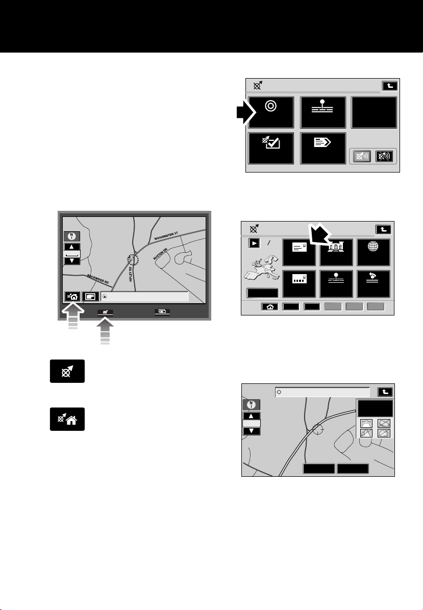
Navigation
The screen allows touch-control of the
navigation system. Only a light touch is
required to operate the function, excess
pressure on the screen could result in damage.
On initial activation, ensure that both the
correct country and area have been selected.
Setting a destination
To set a destination and start using the
navigation system, use the following
procedure:
Navigation Menu
LAN0668
Destination
Entry
Navigation
Setup
Stored
Locations
Route
Options
Touch the Destination Entry icon.
TMC
RDS-TMC
4770 WASHINGTON STREET EXT
1/8 mi
1/16 mi
ROCKW
LAN0706N
OOD RD
HIPLEY RD
Destination
HIPLEY RD, WASHINGTON DC
Press the Navigation button on the
display surround, and when
prompted, touch Agree to access
the initial Home menu.
Touch the Home icon on the screen
to access the navigation menu.
WASHINGTON ST
N DR
RUXTO
Way Point
Route
Preference
Destination Entry
1
2
Select from
Point
Previous
3 4 5
Map
Dest
LAN0669
Change
Address
Postcode
1
2
Point of
Change
Memory
Touch the Address icon, then enter details
using the on-screen keypad.
Touch OK to enter.
4770 WASHINGTON STREET EXT
Route
Preference
RUXTON DR
Way Point
1/16 mi
ROCKWOOD RD
LAN0707N
WASHINGTON ST
HIPLEY RD
Destination
Once found, the screen displays the
destination. To change the route settings,
touch Route Preference, or touch Destination
to start the route calculation.
31

Quick start
Route preferences
When set, route preferences are remembered
and used for calculating all new routes. If you
encounter problems with the type of routes
being selected or the guidance being given,
please check the route preferences.
Once calculated, the screen highlights the
route. Touch 3 Routes to select an alternate
route, or touch Start to start navigation. Drive
away, following the voice guidance.
Touch the audible repeat icon to
hear the last voice instruction
again.
When your destination is reached, voice and
visual confirmation is given.
Cancelling guidance
Touch the Home icon, select Route
options, Cancel guidance and
touch Yes to confirm.
32

Quick start
Telephone – Bluetooth system
Mobile phones with Bluetooth capability can
communicate with the vehicle’s inbuilt
telephone feature.
Mobile phone compatibility
There are a number of mobile phones that
have been tested for full functionality with the
Land Rover system, however not all phones
are compatible and some may only be
partially compatible. For the latest list of
compatible phones and software versions,
please refer to
www.ownerinfo.landrover.com.
Alternatively consult your Dealer.
Nokia Motorola Ericsson
1. Select Menu Select Menu Select Menu
2. Select Settings Select Settings Select Connectivity
3. Select Bluetooth or Select
Connectivity then
Bluetooth
4. Select On Select Bluetooth link Select My Devices
5. Select Search for audio
devices
6. After search select Land
Rover
7. Enter pass code 2121.
Press OK to confirm
8. No connection? Select
Bluetooth (Menu) then
Paired devices Jaguar
Select Connection Select Bluetooth
Select Hands-free With New Device highlighted,
Select Look for devices After search select Land Rover
After search select Land
Rover
Permission to bond?
Select Yes and enter pass
code 2121
Pairing a handset to the vehicle’s system
Prepare the mobile phone for pairing to the
system. See the telephone manufacturer’s
instructions for further details, or follow the
table below for generic commands.
When the handset has been successfully paired
to the system, Bluetooth will appear on the
Phone menu screen.
Note: If more than one paired Bluetooth phone
is in range, the system will automatically select
the last phone used in Bluetooth mode.
select Add. Press OK to
confirm
Select Connect
Enter pass code 2121 after
prompt
33

Quick start
Making a call
1
2
LAN0673
1. With a paired or docked handset, press the
button on the audio unit, or operate
the answer call switch 1 on the steering
wheel controls.
2. Enter the required telephone number using
the numeric keypad.
3. Press the button, or operate the
answer call switch 1 on the steering wheel
to send.
Receiving a call
1
2
LAN0673
To answer an incoming call, press the
button on the audio unit, or operate the answer
call switch 1 on the steering wheel controls.
To end, or reject an incoming call, press the C
button on the audio unit, or operate the end call
switch 2 on the steering wheel.
34

Gas station information
Gas station informati on
GAS STATION INFORMATION
Fuel filler flap location
A small arrow on the fuel gauge
indicates which side the fuel filler
flap is located.
Fuel filler flap opening
CAUTION
The fuel flap has a spring loaded release,
do not force it open.
LAN0675
Press and release the centre of the left edge of
the fuel filler flap (where arrowed) to open.
Refuelling
Insert the pump nozzle into the filler neck,
pushing aside the spring-loaded cover.
When delivery is complete, withdraw the nozzle
and replace the cap. Tighten the cap clockwise
until you hear it click three times. Return the
fuel filler flap to its closed position.
Fuel specification
CAUTIONS
Land Rover petrol engines are not fitted
with equipment necessary for the use of
fuels containing more than 10 per cent
ethanol.
Do not use E85 fuels (85 per cent ethanol
content). If E85 fuels are used serious engine
and fuel system damage will occur.
The correct fuel specification for your vehicle is
shown on the inside of the fuel filler flap. See
TYPE OF FUEL (page 178).
Incorrect fuelling
CAUTION
If the fuel tank is accidentally filled with
the wrong type of fuel, it is essential that
the engine is not started and you seek qualified
assistance.
LAN0680
The filler cap is secured to the vehicle by a
strap. For your convenience a holder is
provided on the flap to store the cap whilst
refuelling.
35

Gas station information
Tire pressures
Air pressure naturally increases in warm tires;
if it is necessary to check the tires when they
are warm (after the vehicle has been driven for
a while), you should expect the pressures to
have increased by up to 30 - 40 kPa (4 - 6 PSI).
In this circumstance, do not let air out of the
tires in order to match the recommended cold
tire pressures. See TIRE CARE (page 225).
Tire pressures label
LAN0708N
The correct tire pressures are shown on a label
attached to the pillar behind the driver’s door.
Temporary spare wheel
The tire pressure in the temporary spare
wheel/tire should be maintained at 420 kPa
(60 PSI) for all loading conditions.
Engine oil specification
Variant Specification
V6 Use only oils certified for
Gasoline Engines by the
American Petroleum
Institute (API). Use a
5W/30 oil meeting
specification
API SM+ILSAC GF4.
V8 Use only oils certified for
Gasoline Engines by the
American Petroleum
Institute (API). Use a
5W/30 oil meeting
specification
API SM+ILSAC GF4.
Land Rover recommends Castrol.
Engine coolant specification
Top-up to the upper level indicator mark
located above the COLD FILL RANGE text, on
the side of the expansion tank. Use only a 50%
mix of water and antifreeze, to specification
LRN2279. Land Rover recommends Castrol SF
antifreeze. See ENGINE COOLANT CHECK
(page 204).
Note: In an emergency - and only if the
approved antifreeze is unavailable - top-up the
cooling system with clean water, but be aware
of the resultant reduction in frost protection.
Do not top-up or refill with conventional
antifreeze formulations. If in doubt consult a
qualified technician.
36
Introduction
Introduction
SYMBOLS GLOSSARY
Warnings
WARNING
Safety warnings are included in this
handbook. These indicate either a
procedure which must be followed precisely,
or information that should be considered with
great care in order to avoid the possibility of
personal injury.
Cautions
CAUTION
Cautions are included in this handbook.
These indicate either a procedure which
must be followed precisely, or information that
should be considered with great care in order
to avoid the possibility of damage to your
vehicle.
Symbols
This recycling symbol identifies
those items that must be disposed
of safely in order to prevent
unnecessary damage to the environment.
This symbol identifies those
features that can be adjusted,
disabled or enabled by a Land Rover
Dealer.
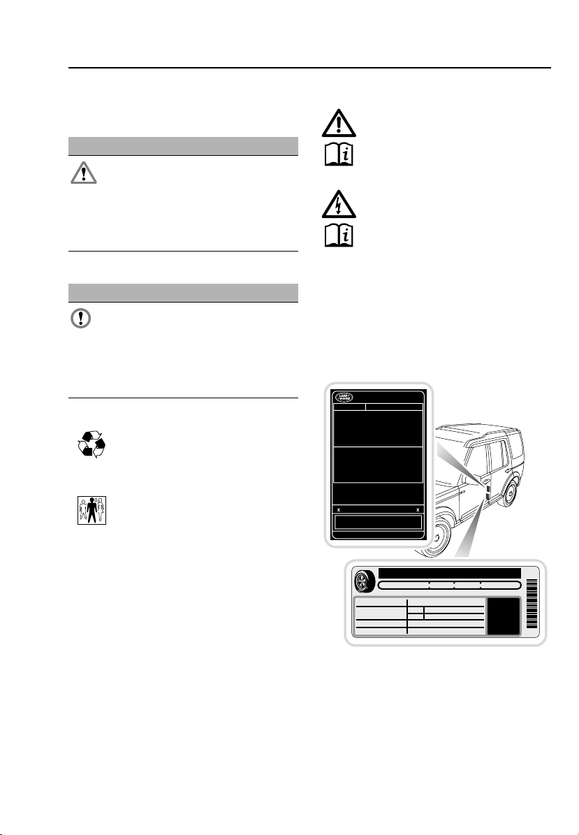
LABEL LOCATIONS
Warning labels attached to your
vehicle bearing this symbol mean: Do
not touch or adjust components until
you have read the relevant instructions
in the handbook.
Labels showing this symbol indicate
that the starter system utilises very
high voltages. Do not touch any
ignition components while the starter
switch is turned on.
Warning labels
Labels are attached to your vehicle at several
positions. These are applied to draw your
attention to important subjects, e.g. tire
pressures, tow bar use, air bags, roll-over risk,
engine compartment hazards, etc.
MFD BY LANDROVER IN THE UK
DATE : MM/YY
GVWR: XXXXKG (XXXXLB)
GAWR FRONT: XXXXKG (XXXXLB)
XXX/XXRXX TIRES, X.XJxXX RIMS, AT XXXKPA (XXPSI) COLD
XXX/XXRXX TIRES, X.XJxXX RIMS, AT XXXKPA (XXPSI) COLD
XXX/XXRXX TIRES, X.XJxXX RIMS, AT XXXKPA (XXPSI) COLD
XXX/XXRXX TIRES, X.XJxXX RIMS, AT XXXKPA (XXPSI) COLD
TXXX/XXR19 TIRES, X.XJxXX RIM, AT XXXKPA (XXPSI) COLD
GAWR REAR: XXXXKG (XXXXLB)
XXX/XXRXX TIRES, X.XJxXX RIMS, AT XXXKPA (XXPSI) COLD
XXX/XXRXX TIRES, X.XJxXX RIMS, AT XXXKPA (XXPSI) COLD
XXX/XXRXX TIRES, X.XJxXX RIMS, AT XXXKPA (XXPSI) COLD
XXX/XXRXX TIRES, X.XJxXX RIMS, AT XXXKPA (XXPSI) COLD
TXXX/XXR19 TIRES, X.XJxXX RIM, AT XXXKPA (XXPSI) COLD
THIS VEHICLE CONFORMS TO ALL APPLICABLE
U.S.FEDERAL MOTOR VEHICLE SAFETY
STANDARDS IN EFFECT ON THE DATE OF
MANUFACTURE SHOWN ABOVE
TESTMARK1234567890
TYPE : MULTI - PURPOSE PASSENGER VEHICLE
TIRE AND LOADING INFORMATION
SEATING CAPACITY
The combined weight of occupants and cargo should never exceed XXXkg or XXXXlbs
ORIGINAL TIRE SIZE COLD TIRE INFLATION PRESSURE
COMPACT SPARE TIRE
E82598
XXX/XXRXX
TXXX/XXRXX
FRONT
REAR
COLD TIRE INFLATION PRESSURE
TOTAL 7
XXXkpa, XXPSI
XXXkpa, XXPSI
XXXkpa, XXPSI
FRONT 2 REAR 3 + 2
SEE OWNER'S
MANUAL FOR
ADDITIONAL
INFORMATION
It is important that you are familiar with these
subjects to ensure that your vehicle and its
features are used safely. Using the index at the
back of this handbook, refer to the relevant
topic for more information.
37
RTC500XXX
Introduction
HEALTH AND SAFETY
WARNINGS
Utility vehicles have a significantly
higher roll-over rate than other types of
vehicles. Since these vehicles are designed to
be operated off-road, these vehicles have a
higher ground clearance and hence, a higher
centre of gravity. Such a feature has been
associated with an increased risk of vehicle
roll-over.
Another factor shown to significantly increase
roll-over risk is unauthorized vehicle
modifications, such as fitting incorrect
specification tires, oversize tires, incorrect
springs/dampers, body lifting or incorrect
vehicle loading/trailer towing.
However, on-road crash data also indicates
that driver behaviour is a greater factor than a
high centre of gravity in determining a
vehicle’s overall roll-over rate. The single most
effective driver behaviour that can reduce the
risk of injury or death in all crashes including
roll-over, is to always wear your seat belt and
to properly restrain all child passengers in the
rear seat in an appropriate child safety seat. In
a roll-over crash, an unbelted person is
significantly more likely to die than a person
wearing a seat belt.
The vehicle is not designed for
cornering at the same speed as
conventional passenger cars any more than a
sports car is designed to perform off-road. If
at all possible, avoid sharp turns or abrupt
manoeuvres. As with other vehicles of this
type, failure to operate the vehicle correctly
may result in loss of control or vehicle
roll-over.
CAUTION
The overall height of your vehicle
exceeds that of ordinary passenger cars.
See TECHNICAL SPECIFICATIONS. Always be
aware of the height of your vehicle and check
the available headroom before driving through
low entrances. This is particularly important if
the vehicle is fitted with a roof rack or if a
sunroof is open.
38

Introduction
DATA RECORDING
Service data recording
Service data recorders in your vehicle are
capable of collecting and storing diagnostic
information about your vehicle. This potentially
includes information about the performance or
status of various systems and modules in the
vehicle such as engine, throttle, steering or
brakes.
In order to properly diagnose and service your
vehicle, Land Rover and service and repair
facilities may access vehicle diagnostic
information through a direct connection to
your vehicle.
Event data recording
Event data recorders are capable of collecting
and storing data during a crash or near-crash
event. The recorded information may assist in
the investigation of such an event. The
modules may record information about both
the vehicle and the occupants, potentially
including information such as:
• How various systems in your vehicle were
operating.
• Whether or not the driver and passenger
seat belts were buckled.
• How far, if at all, the driver was depressing
the accelerator and/or the brake pedal.
• How fast the vehicle was travelling.
• Where the driver was positioning the
steering wheel.
To access this information special equipment
must be connected directly to the recording
modules. Land Rover do not access event data
recorder information without obtaining
consent, unless pursuant to court order or
where required by law enforcement, other
government authorities or third parties acting
with lawful authority.
Other parties may seek to access the
information independently of Land Rover.
PARTS AND ACCESSORIES
WARNINGS
The fitting of non-approved parts and
accessories, or the carrying out of
non-approved alterations or conversions, may
be dangerous and could affect the safety of the
vehicle and occupants and also invalidate the
terms and conditions of the vehicle warranty.
Land Rover will not accept any liability
for death, personal injury or damage to
property which may occur as a direct result of
fitment on non-approved accessories or the
carrying out of non-approved conversions to
Land Rover vehicles.
Land Rover strongly advise against
making any modifications to the
suspension or steering system. This could
seriously affect the handling and stability of
the vehicle leading to loss of control or
roll-over.
The vehicle has been designed, built and tested
to cope with a variety of off-road driving
conditions, some of which can place the
severest possible demands on control systems
and components. As such, fitting replacement
parts and accessories that have been
developed and tested to the same stringent
standards as the original components will
safeguard the continued reliability, safety and
performance of your vehicle.
To augment the vehicle's already impressive
performance, a comprehensive range of Land
Rover approved spare parts and accessories is
available, enabling the vehicle to fulfil a wide
variety of roles, and enhancing and protecting
the vehicle in the many tasks to which it can be
applied.
39

Introduction
Land Rover parts are the only parts built to
original equipment specifications and
approved by Land Rover designers; this means
that every single part and accessory has been
rigorously tested by the same engineering
team that designed and built the vehicle and
can therefore be guaranteed for twelve months
with unlimited mileage.
A full list and description of all accessories is
available from your Land Rover Dealer.
Electrical equipment
WARNING
It is extremely hazardous to fit or
replace parts or accessories, the
installation of which requires the dismantling
of, or addition to, either the electrical or fuel
systems.
Always consult a Land Rover Dealer before
fitting any accessory.
Fitting inferior quality parts or accessories,
may be dangerous and could invalidate the
vehicle warranty.
It is recommended that you always consult a
Land Rover Dealer for advice regarding the
approval, suitability, installation and use of any
parts or accessories before fitting.
Air bag system
WARNING
The components that make up the
air bag system are sensitive to
electrical or physical interference, either of
which could easily damage the system and
cause inadvertent operation or a malfunction
of the air bag module.
To prevent a malfunction of the air bag system,
always consult a Land Rover Dealer before
fitting any of the following:
• Electronic equipment such as a mobile
phone, two-way radio or in-car
entertainment system.
• Accessories attached to the front of the
vehicle.
• Any modification to the front of the vehicle.
• Any modification involving the removal or
repair of any wiring or component in the
vicinity of any air bag system components,
including the steering wheel, steering
column, instrument or facia panels.
• Any modification to the facia panels or
steering wheel.
CALIFORNIA PROPOSITION 65
WARNING
Engine exhaust, some of its constituents and
certain vehicle components contain or emit
chemicals known to the State of California to
cause cancer and birth defects or other
reproductive harm. In addition, certain fluids
contained in vehicles and certain products of
components wear contain or emit chemicals
known to the State of California to cause cancer
and birth defects or other reproductive harm.
Battery posts, terminals and related
accessories contain lead and lead compounds.
Wash hands after handling.
40

Introduction
REPORTING SAFETY DEFECTS
(U.S. ONLY)
If you believe that your vehicle has a defect
which could cause a crash, or could cause
injury or death, you should immediately inform
the National Highway Traffic Safety
Administration (NHTSA) in addition to
notifying Land Rover North America Inc.
If NHTSA receives similar complaints, it may
open an investigation and if it finds that a safety
defect exists in a group of vehicles, it may
order a recall and remedy campaign.
However, NHTSA cannot become involved in
individual problems between you, your Dealer
or Land Rover North America Inc.
To contact NHTSA, you may call the Vehicle
Safety Hotline toll-free at 1-888-327-4236
(TTY: 1-800-424-9153); go to
http://www.safercar.gov; or write to:
Administrator, NHTSA, 400 Seventh Street,
SW., Washington, DC 20590.
You can also obtain other information about
motor vehicle safety from
http://www.safercar.gov.
REPORTING SAFETY DEFECTS
(CANADA ONLY)
If you believe that your vehicle has a defect
which could cause a crash or could cause
injury or death, you should immediately inform
Transport Canada in addition to notifying
Land Rover. To contact Transport Canada, call
their toll-free number: 1-800-333-0510.
41
Keys and remote controls
Keys and remote controls
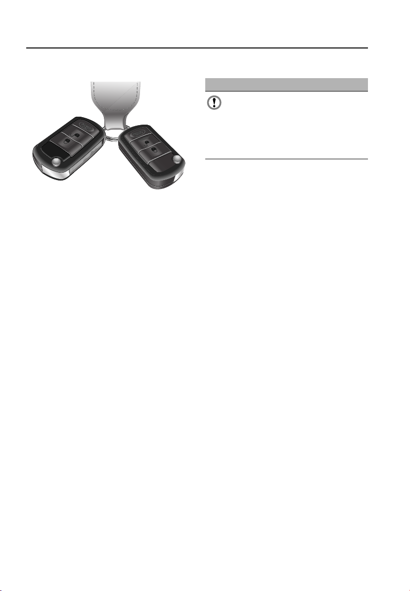
PRINCIPLE OF OPERATION
E81023
You have been supplied with two remote
controls, with integral keys, to operate all the
vehicle’s locks.
The operation of all buttons on all remote
controls, will be inhibited while a key is in the
starter switch.
Note: Interference from other radio equipment,
operating on a similar frequency may affect the
remote control. If this happens, operate the
remote control as close as possible to the
vehicle or use the key.
Note: If the remote control fails to work even
when close to the vehicle, it may not be
synchronised with the system. Start and run
the engine for six minutes to synchronise. If
the remote control still fails to operate, unlock
the vehicle manually. See USING THE KEY
(page 43).
Remote control battery
CAUTION
The remote control contains delicate
electronic circuits and must be protected
from impact, water damage, high
temperatures and humidity, direct sunlight
and the effects of solvents, waxes and abrasive
cleaners.
The battery is rechargeable. If the battery needs
recharging the following will occur:
• KEY BATTERY LOW will be displayed in the
main message centre.
• A gradual deterioration in range and
performance will be noticed.
To recharge the battery, insert the key in the
starter switch and start the engine.
Compliance
The remote control complies with part 15 of the
FCC rules. Operation is subject to the following
conditions:
• This device may not cause harmful
interference.
• This device must accept any interference
received, including interference that may
cause undesired operation.
Any changes or modifications to the remote
control not expressly approved by the
manufacturer or Land Rover North America
could void the user’s authority to operate the
equipment.
Transmitter FCC ID: NT8-15K6014CFFTXA
Receiver FCC ID: LQN5752
42
Keys and remote controls
GENERAL INFORMATION ON RADIO
FREQUENCIES
Note: The radio frequency used by your remote
control may be used by other devices. For
example, amateur radios, medical equipment,
wireless head phones or other remote control
devices. This may cause the frequency to be
jammed and prevent your remote control from
operating correctly.
Environmental conditions can affect the
operation of remote controls, and the operating
range may vary considerably depending on the
vehicle's location.
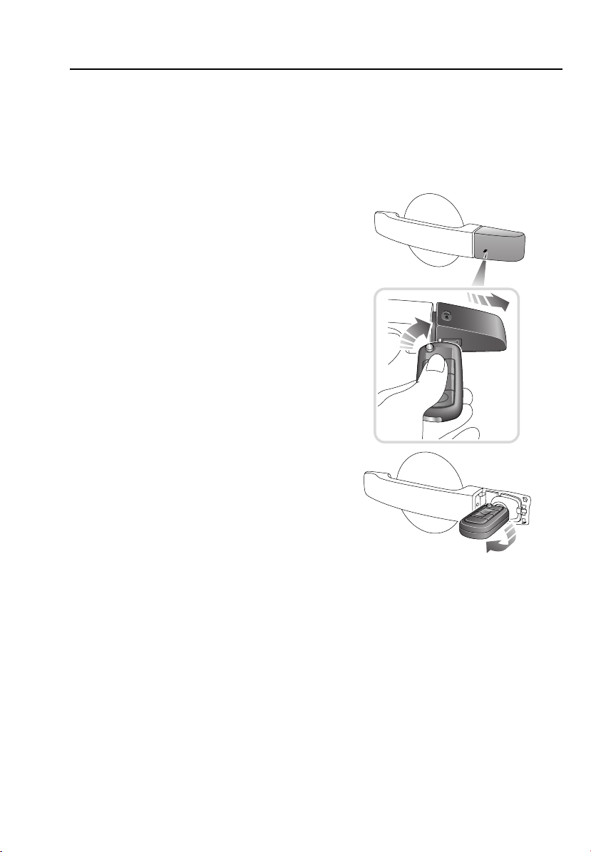
USING THE KEY
Emergency locking and unlocking
Under a removable cap on the left front door
outer handle, there is an emergency-use door
lock.
E80586
1. Insert the key fully into the slot under the
cap and turn clockwise to release the
forward edge of the cap.
2. Remove the cap and withdraw the key.
3. Insert the key into the emergency lock, and
turn counterclockwise to unlock.
4. If the alarm is armed, it will sound when
the door is unlocked. Insert the key in the
starter switch to stop the alarm.
To emergency lock the vehicle, reverse the
above instructions.
43

Keys and remote controls
PROGRAMMING THE REMOTE
CONTROL
The Land Rover button on the remote control
can be programmed to operate one of the
following functions:
• Panic alarm.
• Headlamp courtesy delay.
• Air suspension control.
The currently programmed feature will be
activated when the reprogramming sequence
is started.
The button is disabled when the key is in the
starter switch.
Panic alarm
23
E80563
Press and hold the Land Rover button and
press the hazard warning switch. A chime will
confirm the feature is programmed.
The alarm will sound and the hazard warning
lamps will flash when the button is pressed.
Press the lock or unlock buttons or insert the
key in the starter switch, to switch off the
alarm.
Headlamp courtesy delay
E80564
Press and hold the Land Rover button and flash
the headlamps. A chime will confirm
successful programming.
A short press of the Land Rover button will turn
on the headlamps for the length of time
specified in Settings. See TRIP COMPUTER
(page 108).
A second press of the button after three
seconds, will deactivate the lamps.
Air suspension control
E80565
Press and hold the Land Rover button and
press the suspension raise/lower switch. A
chime will confirm the feature is programmed.
Programming of this function must be done
within one minute of switching off the engine.
Before attempting to raise or lower the
suspension, turn on the hazard warning lamps
and close all the doors.
To raise the suspension, press and hold the
Land Rover button and the lock button.
44

Keys and remote controls
To lower the suspension, press and hold the
Land Rover button and the unlock button.
If any button is released during the raising or
lowering, all movement will stop, until the
buttons are pressed again.
Initially the height will change slowly, but will
increase after three seconds.
While the height is changing, a symbol on the
raise/lower switch will be lit, according to the
direction of movement. See ADJUSTING THE
SUSPENSION (page 172).
If the suspension is not set to On-road height,
all movement will stop when On-road height is
reached. Release the buttons and press again,
to continue. See ADJUSTING THE
SUSPENSION (page 172).
Single-point entry
This feature enables the driver's door to be
unlocked, while leaving the other doors in a
locked state.
Single-point entry can be disabled on individual
remote control keys, by pressing and holding
the lock and unlock buttons for three seconds.
All doors will now unlock with a single press.
Repeating the procedure will re-enable single
point entry.
Each time single-point entry is enabled or
disabled, the vehicle will lock then unlock into
the selected mode.
45
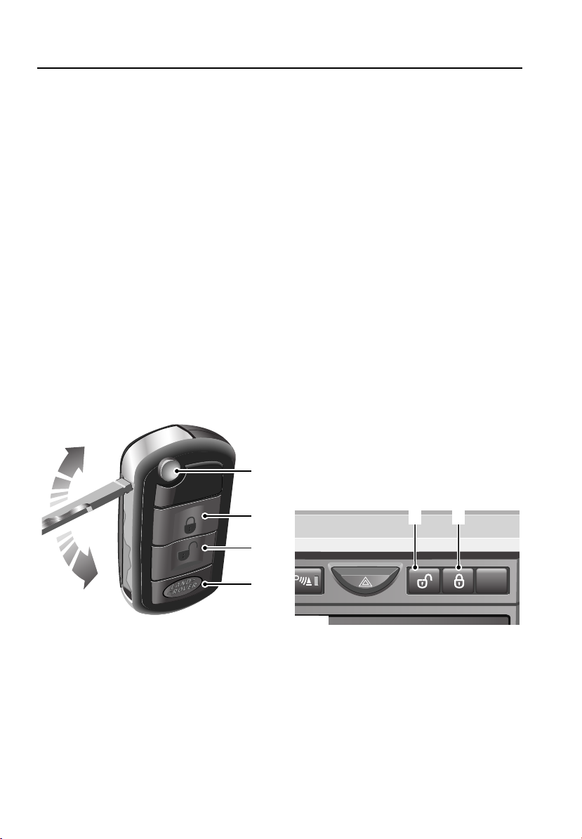
Locks
Locks
LOCKING AND UNLOCKING
To operate, the remote control must be within
range of the vehicle when a button is pressed.
Note: If the remote control fails to work even
when close to the vehicle, it may not be
synchronised with the system. Unlock the
vehicle manually. See USING THE KEY
(page 43). To resynchronise the remote
control, start and run the engine for six
minutes.
Note: If a key is in the starter switch, the
vehicle will not respond to remote control
commands.
Note: If any door or the tailgate is unlocked 10
times within a short period, the latch is
disabled for approximately one minute.
Locking with the remote control
Remove the key from the starter switch and
shut all doors, the hood and the tailgate.
1
• The direction/turn indicators will flash
three times.
3. Unlock button
• Press once to disarm the alarm and
unlock the driver’s door. Press again to
unlock the remaining doors.
• In either case, the interior lamps
illuminate and the direction/turn
indicators flash once.
4. Land Rover button. See PROGRAMMING
THE REMOTE CONTROL (page 44).
Partial locking
If an aperture (door, hood or tailgate) is not
fully closed when the remote control lock
button is pressed, the horn will sound briefly to
signal that an aperture is still open. The alarm
will remain disarmed, but all of the closed
apertures will lock.
As soon as the open aperture is closed, the
system will automatically arm, signalled by
three flashes of the hazard warning lamps, with
interior space protection activating 30 seconds
later.
Master lock and unlock switches
E80759
The four buttons on the remote control are
used as follows:
1. Key release button
2. Lock button
• Press to lock all doors and to activate the
perimetric alarm.
2
1 2
3
4
E80760
1. Press the unlock switch to unlock all the
doors.
2. Press the lock switch to lock all the doors.
46
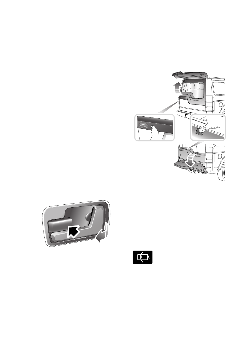
Locks
Speed-related locking
This feature locks all the doors automatically
when the vehicle speed exceeds 8 km/h
(5 mph).
Speed related locking can be disabled. See
TRIP COMPUTER (page 108).
Note: Pressing the master lock or unlock
switch will override the speed locking function
for the journey.
Automatic re-lock
If the vehicle is unlocked using the remote
control and a door, the tailgate or the hood is
not opened within one minute, the vehicle will
re-lock and the alarm will re-arm.
Automatic unlocking
If the vehicle is involved in a collision which
causes a restraints device to deploy, all door
locks will automatically be unlocked, the
hazard warning lamps will flash and the interior
lamps will illuminate.
Interior door handles and door locking
levers
When the master lock or unlock switch is used,
or speed related locking is activated, all door
locking levers will activate automatically.
Opening the tailgate
E80763
Upper tailgate
Unlock the vehicle and press the touch pad on
the underside of the exterior handle. Pull to
open.
Lower tailgate
With the upper tailgate open, press the touch
pad on the lower tailgate waist moulding.
E80762
From inside the vehicle, each door can be
individually locked by depressing the
appropriate lever (arrowed).
To open and unlock a front door, pull the door
handle.
To open a rear door, first return the locking
lever to its unlocked position, then pull the
door handle.
Door open warning indicator
Illuminates when the tailgate or one
of the vehicle's doors is open. On
vehicles with a message centre, the
message DRIVER’S DOOR OPEN will be
displayed, when the driver’s door is open.
47

Engine immobiliser
Engine immobiliser
PRINCIPLE OF OPERATION
CAUTION
The immobiliser may suffer
interference from other legal users of
this frequency band.
Engine immobilisation is an important aspect
of the security system. It is designed to
safeguard the vehicle from theft, should the
driver forget to lock the doors. The system
prevents the engine from being started unless
a genuine remote control key is inserted into
the starter switch.
Engine immobilisation occurs automatically
five seconds after the key is removed from the
starter switch.
Note: The engine will be re-mobilised
automatically whenever a genuine remote
control key is inserted into the starter switch.
When this happens, the anti-theft alarm
indicator will illuminate for one second.
Compliance
The immobiliser system operates on a
frequency subject to USA Federal
Communications Commission (FCC) rules. The
device complies with Part 15 of the FCC rules
and RSS-210 of the industry Canada.
Operation is subject to the two following
conditions:
• The device may not cause harmful
interference.
• This device must accept any interference
received, including interference that may
cause undesired operation.
The immobiliser frequency approval numbers
for the USA and Canada are shown below:
USA FCC ID: TTRT5SJB.
Canada IC: 6276A-T5SJBR1.
Note: Note: The manufacturer is not
responsible for any radio interference or TV
interference caused by unauthorized
modifications to this equipment. Changes or
modifications not expressly approved by the
party responsible for compliance could void
the user's authority to operate the equipment.
CODED KEYS
Note: A replacement remote control can only
be obtained from your Land Rover Dealer. The
Dealer will require proof of ownership.
Notify your Dealer immediately if a remote
control is lost or stolen.
48

Alarm
Alarm
PRINCIPLE OF OPERATION
E81206
Your vehicle is fitted with a sophisticated
electronic anti-theft alarm system. There are
also a number of additional security features,
some of which are selectable options and some
are standard features of the vehicle.
In order to ensure maximum security and
operating convenience, you are strongly
advised to gain a full understanding of the
features and alternatives available, by
thoroughly reading this section of the
handbook.
ARMING THE ALARM
Perimetric alarm
This feature is activated automatically
whenever the vehicle is locked using the
remote control and protects the doors, hood
and tailgate.
If any of these apertures are opened, or if an
unknown key is inserted into the starter switch,
the alarm will be triggered.
When the perimetric alarm is activated, the
direction/turn indicators will flash three times,
and the anti-theft alarm indicator will flash.
Partial arming
If an aperture (door, hood or tailgate) is not
fully closed when the remote control lock
button is pressed, the horn will sound briefly to
signal that an aperture is still open. The alarm
will remain disarmed, but all of the closed
apertures will lock.
As soon as the open aperture is fully closed,
the system will automatically arm, signalled by
three flashes of the hazard warning lamps, with
interior space protection activating 30 seconds
later.
Anti-theft alarm indicator
E80560
The indicator provides information about the
status of the alarm and immobiliser systems,
as follows:
Alarm status Indicator
Armed Double flash for 10
seconds, then single
flash
Disarmed, engine
immobilised
Disarmed, engine
mobilised
Single flash
A one second flash
49

Alarm
SWITCHING OFF THE ALARM
If the alarm is triggered, the alarm will sound
and the hazard warning lamps will flash for 30
seconds, before resetting to the same
protection status that existed prior to the alarm
being triggered.
To silence the alarm, press the lock or unlock
button on the remote control or insert the key
into the starter switch. Pressing the lock button
will keep the alarm armed.
If the alarm has been activated since it was last
armed, the hazard warning lights will flash
rapidly for eight seconds when the alarm is
disarmed.
PANIC ALARM
The Land Rover button on the remote control
can be programmed to operate the panic alarm.
See PROGRAMMING THE REMOTE CONTROL
(page 44).
The alarm will sound and the hazard warning
lamps will flash when the button is pressed.
Press the lock or unlock buttons or insert the
key in the starter switch, to switch off the
alarm.
50

Seats
Seats
SITTING IN THE CORRECT POSITION
WARNINGS
Do not adjust the driver's seat while the
vehicle is in motion, this may cause
loss of control and personal injury.
Optimum benefit is obtained from the
seat belt with the backrest angle set to
no more than 30 degrees from the upright
(vertical). Failure to maintain the correct
backrest angle will reduce the effectiveness of
the seat belt and increase the risk of serious
injury or death in a crash.
A
B
E80441
The seat, head restraint, seat belt and air bags
all contribute to the protection of the user.
Correct use of these components will give you
more protection therefore observe the
following points:
1. Sit in an upright position with the base of
your spine as far back as possible and the
backrest reclined not more than 30
degrees A.
2. Adjust the position of the seat. A minimum
distance B of at least 254 mm (10 inches)
between the centre of the breastbone and
the steering wheel is recommended.
• The driver should hold the steering
wheel with their arms slightly bent.
• The legs should also be slightly bent so
that the pedals can fully be pressed to
the floor.
3. Position the seat belt across the centre of
your shoulder. Fit the lap strap tightly
across your hips and not across your
stomach.
Make sure that your driving position is
comfortable and enables you to maintain full
control of the vehicle.
51

ELECTRIC SEATS
Seats
2
1
3
4
1
4
E83535
1. Forward/backward adjustment
2. Backrest adjustment
WARNING
Do not adjust any part of a seat while
the vehicle is in motion. Vehicle
movement may cause the seat to suddenly
shift, potentially causing injury.
The seat adjustment controls are situated on
the outboard side of the seat cushion. The
position of the seat can be adjusted when the
starter key is in position I or II.
2
3
3. Seat cushion height adjustment
4. Seat cushion edge adjustment
In addition, the seats have a 15 minute (10
minutes for a driver's seat with seat memory)
active period initiated when:
• the driver’s door is opened or closed, or
• the starter key is turned to position 0.
52

Seats
Lumbar support adjustment
E82949
A separate switch, located on the side of the
driver’s seat, adjusts the lumbar support.
Press the front of the switch to increase lumbar
support, or the rear of the switch to reduce the
support.
Folding armrest
E80439
The height of the armrest can be adjusted by
turning the knob clockwise to raise or
counterclockwise to lower. The armrest can be
stowed vertically alongside the backrest.
53

Seats
HEAD RESTRAINTS
WARNINGS
Head restraints are designed to support
the back of the head (not the neck), and
to restrain rearward movement in the event of
a collision. The restraint must be correctly
positioned to be effective.
Do not drive or carry passengers with
the head restraints removed from
occupied seats.
Do not adjust the head restraints while
the vehicle is in motion.
Failure to have the head restraints
installed and properly positioned will
increase the potential for serious injuries.
Front head restraints
Note: The front head restraints are an integral
part of the seat, and are not designed to be
removed or adjusted.
Rear head restraints
Adjustment
E81310
1. Press the collar button.
2. Raise or lower the head restraint until the
top of the head restraint is level with the
top of the head.
Removal
To remove the head restraint, press the collar
button whilst lifting the restraint clear of the
seat.
To replace the head restraint, engage the guide
posts into the collars and press the restraint
downwards until a click is heard.
54

Seats
REAR SEATS
WARNING
Do not adjust any part of a seat while
the vehicle is in motion. Vehicle
movement may cause the seat to suddenly
shift, potentially causing injury.
Second-row seats - 5-seat vehicle
Note: Some 5-seat models are fitted with the
same type of seat as the 7-seat model.
Folding the seats
One or both parts of the seat can be folded.
Move the front seats forward and remove any
items from the seats and the rear footwell.
1
2
2
3
4
4
E80411
4. Lower the backrest until it locks into place.
Note: Only Land Rover-approved seat covers
and accessories should be used on these seats.
Raising the seats
1
2
E80412
1. Pull the strap vertically on the back of the
seat to unlock the seat. Continue to pull to
raise the backrest(s) until they click into
position.
2. Push the seat cushion(s) firmly back into
position.
3. If the lever has not returned to its locked
position, red flags will be visible around
the lever.
4. Pull the head restraint up into the correct
position.
1. Fully lower the head restraints.
2. Pull the strap on the required cushion(s),
to raise the cushion to the vertical position.
3. Pull the seat backrest release lever(s)
forward.
55

Seats
Second-row seats - 7-seat vehicle
WARNING
Do not adjust any part of a seat while
the vehicle is in motion. Vehicle
movement may cause the unlatched seat to
suddenly shift, potentially causing injury.
The seats can be used in a variety of
configurations:
• As a standard row of three seats.
• A backrest can be folded forwards to form
a table.
• One or all seats can be folded flat.
• An outer seat can be folded forwards for
access to the third row of seats.
If the front seats are in their rearmost position,
move them forward prior to folding down the
seats.
Table fold position
WARNING
The latching mechanism should be
checked and physically tested to ensure
that both the cushion and backrest are secure
before driving.
Remove any items from the seats and rear
footwell. Fully lower the head restraint on the
seat(s) to be folded.
1
2
E80413
1. Pull the backrest release lever forwards.
2. Lower the backrest forwards into the
table-fold position.
Note: Only Land Rover-approved seat covers
and accessories should be used on these seats.
To return the seat-back to its upright position,
push the release lever forwards and pull the
backrest up until it clicks into place.
If it has not returned to its locked position, red
flags will be visible around the lever.
Pull the head restraint up to its correct
position.
56
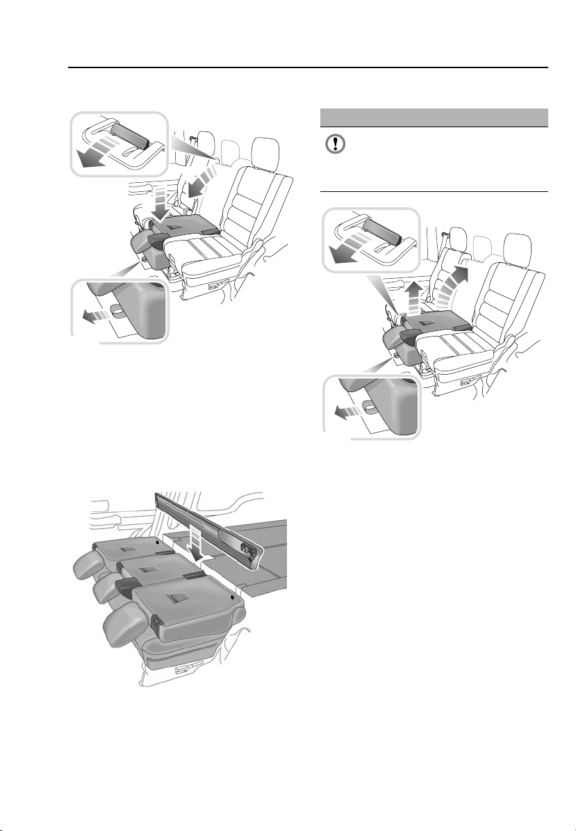
Seats
Extending the loadspace
1
2
4
3
E80414
1. Pull the backrest release lever forwards.
2. Lower the backrest forwards into the
table-fold position.
3. Pull the strap at the front of the seat
4. Press down on the seat.
Note: The centre seat must always be folded
first.
E81904
Raising the seat
CAUTION
Do not attempt to raise the seats from
the loadspace position while the
loadspace cover unit is stowed behind it as
damage to the unit or seats will result.
3
2
4
1
E80415
1. To raise the seat, pull the strap at the front
of the cushion.
2. Grasp the top and bottom of the backrest,
lift the seat and return it to the table-fold
position.
3. Push the release lever forward.
4. Pull the backrest up and push until the
latching mechanism clicks into place.
If the lever has not returned to its locked
position, red flags will be visible around the
lever.
Note: If a combination of backrests, including
the centre backrest, is to be erected, the centre
backrest should be erected last.
Remove the luggage cover and stow it between
the folded seat rows.
57

Seats
Access position
WARNING
The outer seat(s) must not be left in the
access position while the vehicle is
being driven. Motion of the vehicle could
cause the seat to drop back into its table-fold
position.
To enter the third-row seats, first ensure that
the head restraint on the second-row seat is
fully lowered.
1
2
4
Note: A second-row seat cannot be moved
from the loadspace position to the access
position. Return the seat to the table-fold
position before attempting to move it to the
access position.
Raising the seat
WARNINGS
When lowering the seats from the
access position, ensure that nothing is
trapped by the returning seat.
The latching mechanism should be
checked and physically tested to ensure
that the cushion and backrest are secure
before driving.
Pull the seat down into the table-fold position.
The access lever will click into place. Check
around the lever, a red flag will be visible
behind the lever if the backrest is not correctly
located.
3
E80416
1. Pull the backrest release lever forwards.
2. Lower the backrest forwards into the
table-fold position.
3. Pull the access lever on the side of the
seat.
4. Tilt the seat forwards.
Once access to the third-row seat has been
gained, return the second-row seat to its fully
upright position.
58

Seats
Third-row seats
Third-row seats can be folded flat.
WARNINGS
Ensure that nothing has been left under
the seat or in the footwell when folding
down the seat as this could cause damage.
Beware of potential finger traps when
operating the seats.
CAUTION
Do not attempt to raise the seats from
the loadspace position while the
loadspace cover is in its floor level stowage
position as this may damage either the cover
or the seats.
Folding the seat
1
3
5
2
4
6
E80417
1. Press the head restraint release button.
2. Fold the head restraint fully downwards.
3. Pull up the release strap at the rear corner
of the cushion; this lifts under spring
pressure.
4. Fold the cushion fully forwards until it
latches into position.
5. Pull up the backrest release lever.
6. Fold the backrest fully forwards until it
latches into position in the loadspace floor.
59
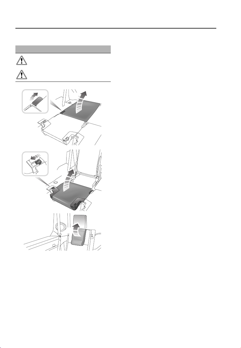
Seats
Raising the seat
WARNINGS
The head restraint must always be
raised when using the third-row seat.
Do not use the seat until it is fully
raised.
1
3
4
5. Raise the head restraint until it latches into
position.
Note: When not in use, the head restraints
should be folded to improve rear vision.
2
5
E80418
1. Pull lever to release backrest.
2. Raise the backrest into its upright position,
ensuring that it is fully latched into place.
3. Release catch and raise cushion.
4. Push the cushion into place, ensuring that
the cushion is latched to the backrest.
60
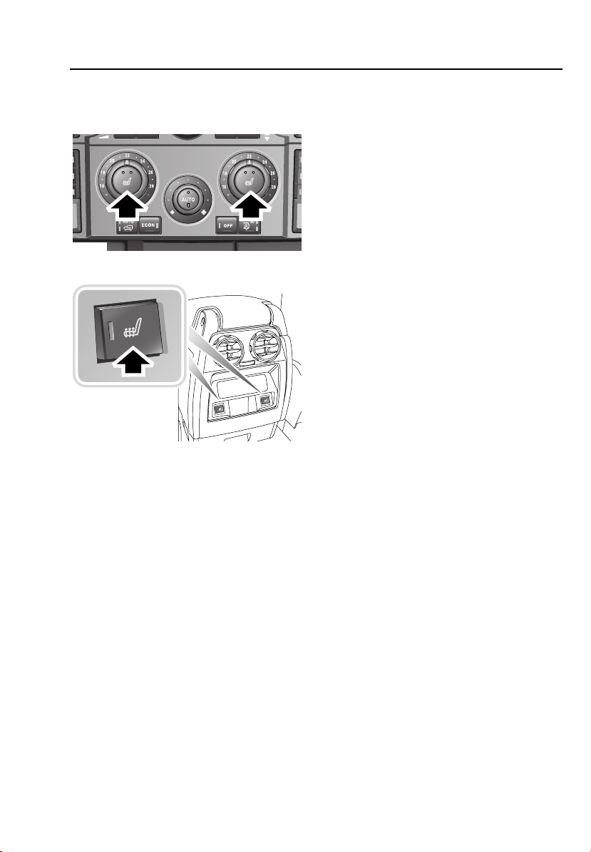
Seats
HEATED SEATS
Front seat heaters
E80400
Rear seat heaters
E80401
With the starter switch turned on, the seat
cushion and backrest can be heated at two
different settings.
• Press once to operate at the high setting
(both indicators illuminate). As cabin
temperature rises, the heaters will switch
to the low setting and one light will
extinguish.
• Press twice to operate at the low setting
(one indicator illuminates).
• Press a third time to turn off the heaters
(both indicators will extinguish).
The seat heaters are thermostatically
controlled and will maintain a factory-set
temperature.
Note: The seat heaters consume considerable
power from the battery. It is recommended that
they are only operated while the engine is
running.
61

Seat belts
Seat belts
GENERAL INFORMATION
WARNINGS
Seat belts are life saving equipment. In
a collision, occupants not wearing a
seat belt can be thrown around inside or
possibly thrown out of the vehicle. This is
likely to result in more serious injuries than
would have been the case had a seat belt been
properly worn. It may even result in loss of life.
Make sure all occupants are securely
strapped in at all times - even for the
shortest journeys.
The air bag supplemental restraint
system is designed to add to the overall
effectiveness of the seat belts. It does not
replace them. Seat belts must always be worn.
Seat belts are designed to bear upon
the bony structure of the body and
should be worn low across the pelvis, or pelvis
chest and shoulders, as applicable; wearing
the lap section of the belt across the
abdominal area must be avoided.
Do not wear seat belts over hard, sharp
or fragile items in clothing, such as
pens, keys, spectacles, etc.
Seat belts should be adjusted as firmly
as possible, consistent with comfort, to
provide the protection for which they have
been designed. A slack belt will greatly reduce
the protection afforded to the wearer.
Do not allow front seat occupants to
travel with the seat backs reclined
steeply rearwards. Optimum benefit is
obtained from the seat belt with the seat back
angle set to no more than 30 degrees from the
upright.
Belts should not be worn with the
straps twisted.
WARNINGS
Ensure that all seat belts are worn
correctly - an improperly worn seat belt
increases the risk of death or serious injury in
the event of a collision.
Each belt assembly must only be used
by one occupant; it is dangerous to put
a belt around a child being carried on the
occupant’s lap.
It is essential to replace the entire
assembly after it has been worn in a
severe impact, even if damage to the assembly
is not obvious.
No modifications or additions should
be made by the user, which will either
prevent the seat belt adjusting devices from
operating to remove slack, or prevent the seat
belt assembly from being adjusted to remove
slack.
Should the seat belt not retract and
remain at its static length, consult your
Land Rover Dealer.
Care should be taken to avoid
contamination of the webbing with
polishes, oils and chemicals and particularly
battery acid. Cleaning may safely be carried
out using mild soap and water. The belt should
be replaced if webbing becomes frayed,
contaminated or damaged.
Where possible, use the seat belts to
secure large items of luggage that are
to be carried on the seats. In the event of an
accident, unsecured items become flying
missiles, capable of causing serious injury.
Never wear just the lap strap of a
lap/shoulder diagonal seat belt and
never sit on the lap strap using just the
shoulder strap. These actions are extremely
dangerous and increase your risk of serious
injury.
62

Seat belts
Seat belts
Lap/shoulder inertia reel seat belts are
provided for both front seat occupants and all
rear seat positions.
The inertia reel operating mechanism of the
seat belts, allows the wearers to move their
upper bodies to reach various controls.
The seat belts include a buckle sensor, to
detect when the buckle is latched.
Caring for seat belts
Regularly inspect the belt webbing for signs of
fraying, cuts and wear; also pay particular
attention to the condition of the fixing points
and adjusters.
Do not bleach or dye the webbing and avoid
contaminating the webbing with polish, oil or
chemicals. See FASTENING THE SEAT BELTS
(page 64).
Testing inertia reel belts
• With the seat belt fastened, give the
webbing near the buckle a quick upward
pull. The buckle must remain securely
locked.
• With the seat belt unfastened, reel out the
webbing to the limit of its travel. Check that
unreeling is free from snatches and snags
and then allow the belt to fully retract.
• Partially unreel the webbing, then hold the
tongue plate and give it a quick forward
pull. The mechanism must lock
automatically and prevent any further
unreeling.
If a seat belt should fail any of these tests, seek
qualified assistance.
Note: If the vehicle is parked on ground that is
not level, the seat belt mechanism may lock.
This is not a fault; gently ease the belt from the
upper anchorage to release.
Seat belt pre-tensioners
WARNINGS
The seat belt pre-tensioners will only be
activated once and then must be
replaced by a Land Rover Dealer. Failure to
replace the pre-tensioners will reduce the
efficiency of the vehicle's front restraint
systems.
After any impact, always have the seat
belts and pre-tensioners checked and,
if necessary, replaced by a Land Rover Dealer.
In the interests of safety, it is
recommended that removal or
replacement of the front seats and seat belts
should only be carried out by a Land Rover
Dealer.
The seat belt pre-tensioners activate in
conjunction with the air bags and provide
additional protection in the event of a severe
frontal impact on the vehicle. The
pre-tensioners automatically retract the seat
belts fitted to the front seats. This reduces any
slack in both the lap and diagonal portions of
the belts, thereby reducing forward movement
of the belt wearer in the event of a severe
frontal collision.
The air bag warning indicator on the
instrument pack, will alert you to any
malfunction of the seat belt pre-tensioners.
If the pre-tensioners have been activated, the
seat belts will still function as restraints and
must be worn in the event that the vehicle
remains in a driveable condition.
Note: The seat belt pre-tensioners will be
activated in major side and frontal impacts and
in roll-overs.
63

Seat belts
SEAT BELT REMINDER
Beltminder commences when the
starter switch is turned to position II
and the driver's belt is unbuckled.
The warning indicator in the instrument pack
illuminates, the message FASTEN SEAT BELTS
appears in the message centre and a warning
chime sounds for six seconds or until the seat
belt is fastened (whichever occurs first).
If the seat belt remains unfastened, the chime
will sound at intervals of 15 seconds.
The Beltminder feature also applies to the front
passenger seat and will be activated if the seat
is occupied and the occupant's seat belt is
unbuckled.
Note: Objects placed on the passenger seat
may activate the seat belt warning system.
Although not advisable, it is
possible to disable the Beltminder
function. Please see a Land Rover
Dealer to disable or reinstate the function.
FASTENING THE SEAT BELTS
E80379
Insert the metal tongue plate into the buckle
nearest the wearer. A click indicates that the
belt is securely locked.
The buckles on third-row seats are
spring-loaded allowing them to be stowed
within the seat. This is to prevent damage when
the seats are folded flat. To fasten the belt, pull
the buckle up from the seat before inserting the
tongue plate.
Adjust the seat belt to eliminate any slack in the
webbing.
Releasing the belt
Press the red button on the seat belt buckle.
64

Seat belts
SEAT BELT HEIGHT ADJUSTMENT
WARNING
Maladjustment of the seat belt could
reduce its effectiveness in a crash.
Always ensure that the anchorage is correctly
located and properly locked in one of the
height positions before driving and do not
adjust the height once the vehicle is in motion.
E80375
Press down (solid arrow) to release the catch,
then lift or push down to adjust the height of
the anchorage.
Ensure the anchorage has clicked into one of
the locked positions before driving.
Where possible passengers should adjust their
position on the seat to enable the seat belt
webbing to cross the shoulder without
pressing on the neck.
USING SEAT BELTS DURING
PREGNANCY
WARNINGS
Pregnant women must wear a correctly
positioned seat belt; it is safer for
mother and unborn child.
Never place anything between you and
the seat belt in an attempt to cushion
the impact in the event of an accident. It can be
dangerous and reduce the effectiveness of the
seat belt in preventing injury.
E80374
During pregnancy, Women should wear the
belt across the hips below the baby, with the
diagonal belt passing across the shoulder,
between the breasts and to one side of the baby
- if in doubt, consult a doctor.
65

Supplementary restraint systems
Supplementary restraint systems
PRINCIPLE OF OPERATION
5 4 3 2 1
E82231
WARNINGS
Always remember; the air bags are a
supplemental restraint system
providing additional protection in certain types
of collision only - they do not replace the need
to wear a seat belt. To reduce the risk of severe
injury or death in the event of a crash, all
occupants in all seating positions, including
the driver, should always wear their seat belt,
whether or not an air bag is present at that
seating position.
An inflating air bag can cause facial
abrasions and other injuries. Minimise
the risk of injury by ensuring that the front seat
occupants are seated correctly, with the seat
as far back as is practical.
Ensure that a gap is maintained
between the side of the vehicle and the
head and torso, to enable unobstructed
inflation of the curtain and seat mounted side
air bags. Do not lean out of the window.
3
The air bag supplementary restraint system
incorporates front air bags 1 and 2, seat
mounted side air bags 3 and curtain air bags 4
for the front seat occupants driver and curtain
air bags 5 for occupants in the rear seat
outboard positions (see illustration for air bag
locations). These are indicated by the word
AIR BAG on the trim.
Provided the occupants are correctly seated,
with the seat belts properly worn; in the event
of a severe frontal impact, the air bags will
provide additional protection to the chest and
face of the front seat occupants.
In the event of a severe side collision, air bags
provide additional protection to the side of the
head and body facing the impact for front seat
occupants and to the side of the head facing
the impact for outer rear seat occupants.
Note: Inflation and deflation of the front and
seat mounted side air bags takes place very
quickly and will not protect against the effects
of secondary impacts that may occur. Head
air bags deflate at a slower rate and therefore
do offer some additional protection in the event
of a secondary impact.
66

Supplementary restraint systems
How the air bag system works
Operation of the air bag system is dependent
on the rate at which the vehicle's passenger
compartment changes speed as a result of a
collision. The circumstances affecting different
collisions (vehicle speed, angle of impact, type
and size of object hit, for example), vary
considerably and will affect the rate of
deceleration accordingly.
In the event of a collision, the air bag control
unit monitors the rate of deceleration induced
by the collision, to determine whether the
air bags should be deployed.
When deployed, inflation of the air bags is
virtually instantaneous and occurs with
considerable force, accompanied by a loud
noise. The inflated bag, together with the seat
belt restraint system, limit the movement of an
occupant, thereby reducing the risk of injury to
the head and upper torso.
The air bag system is not designed to operate
as a result of:
• Rear collisions.
• Minor front impacts.
• Minor side impacts.
• Heavy braking.
• Driving over bumps or potholes.
However, if as a result of an impact, you believe
the air bags should have deployed and they
have failed to do so, please call
1(800)637-6837 for advise, or arrange for a
Land Rover representative to inspect the
vehicle to determine whether the system
operated correctly.
It follows, therefore, that significant superficial
damage can occur without the air bags
deploying or, conversely, that a relatively small
amount of structural damage may cause the
air bags to be deployed.
Obstruction of air bags
WARNINGS
Do not allow passengers to obstruct the
operation of the air bags by placing
feet, knees or any other part of the body, or
any other objects in contact with, or in close
proximity to, an air bag module.
Do not attach or position items on, or
close to the roof lining, A, B and C pillar
finishers, front seat bequests or to an air bag
cover, which could interfere with the inflation
of the air bag or be propelled inside the vehicle
causing injury to the occupants.
ABC
E80487
Do not use non-approved seat
covers/accessory seat covers over a front seat;
in particular, seat covers that have not been
designed for use with side air bags. If in doubt,
consult your Land Rover Dealer.
Note: Unauthorised modification of the vehicle
or parts may invalidate the vehicle’s warranty.
67

Supplementary restraint systems
Deployment effects
WARNINGS
Following inflation, some air bag
system components are hot - do not
touch until they have cooled.
Even with an air bag system fitted, seat
belts must always be worn.
An air bag will only provide additional
protection in certain types of frontal
collisions. No protection is afforded against
the effects of rear impacts, or minor frontal
impacts.
Inflation and deflation take place
instantaneously and will not provide
protection against the effects of secondary
impacts that can occur during multiple vehicle
collisions.
The air bag module inflates with
considerable speed and force. An
inflating air bag can cause facial abrasions and
other injuries. The injurious effects of air bag
inflation can be reduced by ensuring driver
and passenger are seated correctly with the
seat moved back as far as is practical, and the
seat belts worn correctly.
National Highway Traffic Safety
(NHTSA) recommends a minimum
distance of 25 cm (10 inches) between an
occupant’s chest and the driver’s air bag
module.
Never attach accessory items to an
air bag module cover.
WARNINGS
When an air bag inflates, a fine powder
is released. This is not an indication of
a malfunction. However, the powder may
cause irritation to the skin and should be
thoroughly flushed from the eyes and any cuts
or abrasions of the skin. The powder may also
cause possible breathing difficulties for
asthma sufferers or other people with
respiratory problems. If an air bag is activated,
any occupant who suffers from breathing
difficulties should either leave the vehicle as
quickly as possible, or obtain fresh air by fully
opening the windows and doors.
Both front seating positions are
equipped with knee bolsters to provide
knee protection in the event of an impact. Do
not modify the bolsters or mount after market
equipment on or behind them.
After inflation, the front and seat mounted side
air bags deflate immediately (curtain air bags
deflate slowly). This provides a gradual
cushioning effect for the occupants and also
ensures that the driver's forward vision is not
obscured.
Disability modifications
Occupants with disabilities that may require the
vehicle to be modified must contact a Land
Rover Dealer before any modifications are
made.
68

Supplementary restraint systems
SIDE AIR BAGS
WARNING
Ensure that a gap is maintained
between the side of the vehicle and the
torso, to enable unobstructed inflation of the
seat-mounted side air bags.
Side air bags are designed to protect the thorax
region of the torso and will only deploy in the
event of a severe side impact. They will not
inflate as a result of frontal or rear impacts
only.
In the event of a severe side collision, the
air bags on the impacted side of the vehicle
deploy from the side of the seat-back, rapidly
inflating to form a cushion between the front
seat occupants and the side of the vehicle. The
air bags on the non-impacted side of the
vehicle will not be deployed.
CURTAIN AIR BAGS
WARNING
For the curtain air bags to deploy
correctly, the roof lining and A pillar
trim must be undamaged and fitted correctly.
Any damage or suspect fitting should be
referred to a Land Rover Dealer for
examination.
Curtain air bags are designed to protect the
head in the event of a severe side impact or
roll-over event. They will not inflate as a result
of frontal or rear impacts alone.
In the event of a severe side collision, the
air bag pushes out from behind the roof lining
and A pillar trim as it inflates.
OCCUPANT DETECTION
The front passenger seat is fitted with an
occupancy sensor system that determines if
the seat is unoccupied, occupied by a person of
low weight, a child seat or object, or is
occupied by a heavier person or object.
The system consists of:
• A weight sensing pressure pad installed
under the front passenger seat cushion.
The sensor measures downward
pressure/weight on the seat cushion.
• A seat belt tension sensor integrated into
the anchor point of the front passenger
seat belt.
• A control unit installed under the front
passenger seat.
• An air bag status indicator lamp, mounted
on the instrument panel.
69

Supplementary restraint systems
The system will adjust the passenger air bag
status and operate the status indicator as
follows:
Seat
occupancy
status
Completely
Passenger
air bag
status
Status
indicator
active
Deactivated No
†
empty
Child seat or
Deactivated Yes
low weight
occupant/
object
Heavy
Activated No
occupant/
object
The operational status indicator is located on
the passenger’s side of the instrument panel.
†
It is possible to receive an intermittent
indicator with an empty seat condition. This is
part of the system’s adaptive behaviour, and
does not affect the status of the passenger
air bag. However, if the indicator becomes
permanently illuminated when the seat is
definitely empty, then contact your Land Rover
Dealer immediately.
Do not use a child restraint on a seat protected
by an operational air bag in front of it.
There is a risk of death or serious injury when
the air bag deploys.
The safest place for children is properly
restrained in the rear seats.
PASSENGER AIR BAG STATUS
INDICATOR
WARNINGS
Always check the status indicator with
the starter key in position ll.
E82986
The passenger air bag operational status
indicator is an oblong lamp which illuminates
yellow when the starter switch is turned to
position II and the passenger air bag is
deactivated.
6CD-465
70

Supplementary restraint systems
AIR BAG WARNING LAMP
A red warning indicator in the
instrument pack will alert you to any
malfunction of the air bag system.
On vehicles with a message centre, this will be
accompanied by the message AIR BAG FAULT.
Seek qualified assistance urgently if any of the
following symptoms occurs:
• The warning indicator fails to illuminate
when the starter switch is turned to
position ll.
• The warning indicator fails to extinguish
within approximately four seconds after
the starter switch is turned to position Il.
• The warning indicator illuminates after the
engine is started, or while the vehicle is
being driven.
When the starter switch is turned to position II,
the diagnostic control unit monitors the
readiness of the system’s electrical circuits.
The elements of the system being monitored
include:
• SRS warning indicator.
• Rotary coupler.
• Air bag modules.
• Seat belt pre-tensioners.
• Air bag diagnostic control unit.
• Crash sensors.
• Air bag wiring harness.
• Seat occupancy sensor.
AIR BAG WARNING LABELS
front
ta
E82642
Air bag warning information is printed on the
driver’s and front passenger’s sun visor.
71

Supplementary restraint systems
AIR BAG SERVICE INFORMATION
WARNING
For your safety a Land Rover Dealer
must carry out any of the following
tasks.
Removal, replacement, repair, or modification,
of any wiring or component in the vicinity of
the SRS components, including the steering
wheel, steering column, door trim, roof lining,
instrument pack and instrument panel.
Installation of electronic equipment such as a
mobile phone, two-way radio or in-car
entertainment system.
Modification to the front or side of the vehicle,
including the bumper and chassis.
Attachment of accessories to the front or side
of the vehicle.
In addition, always contact your Land Rover
Dealer if:
• An air bag inflates.
• A pre-tensioner activates.
• The front or side of the vehicle is damaged,
even if the air bag has not inflated.
• Any part of an air bag module cover shows
signs of cracking or damage.
• Any trim containing air bags - front seat
back, headlining or pillar trims - becomes
damaged.
72

Facia overview
Warning indicators (information)
The following will illuminate during normal driving to indicate that a particular system or
8 9 10 11764321 5
feature is operating. If any other warning indicator illuminates, refer to Owner’s Handbook.
Side lamps on
Headlamp high beam on
Rear fog lamps on
Front fog lamps on
Electric parking brake on
22
123
ABC DEF
456
JKL MNOGHI
789
TUV WXYZPQRS
0
CD 3 14 : 54
2Tr 15:43
123456
Seat belt reminder
Door open
LOW gear range selected
6CD-465
Hill Descent Control (HDC) on
Cruise control active
Direction indicator
21
20
19
18
12
13
14
Wipers and washers
5
3
2
17
1
Direction indicators/headlamps/trip
computer switch
2
Cruise control switches
3
Instrument pack/warning indicators and
message centre
4
Audio/telephone switches
5
Wiper/washer switch
6
Audio system
7
Dynamic stability control (DSC) switch
8
Touch screen
9
Hazard warning switch
10
Master locking switches
11
Passenger air bag status indicator
10
12
Heater/air conditioning controls
13
Gear selector
14
Terrain response control switch
15
Transfer gearbox switch
16
Hill Descent Control switch
17
Air suspension control
18
Electric parking brake
19
Starter switch
20
Steering column adjustment
21
Hood release
22
Exterior lamps master switch
15
16
B
Windshield wiper
1. Intermittent wipe or rain sensor operation.
2. Normal speed operation.
3. High speed operation.
4. Single wipe - press down and release to
operate.
5. Rotate collar to adjust speed of intermittent
wipe or sensitivity of the rain sensor.
Intermittent wipe Rain sensor
Short delay. Most sensitive
to rain.
Long delay. Least sensitive
to rain.
1
0
A
Windshield washer
Press and hold the button to operate the
windshield washer and wipers.
Rear wiper and washer
Pull the lever to position A for intermittent
operation of the rear wiper. Pull and hold the
lever in position B to operate the rear washer
and wiper.
4
Press and release the button on the end of
the lever to operate the windshield washer.
11
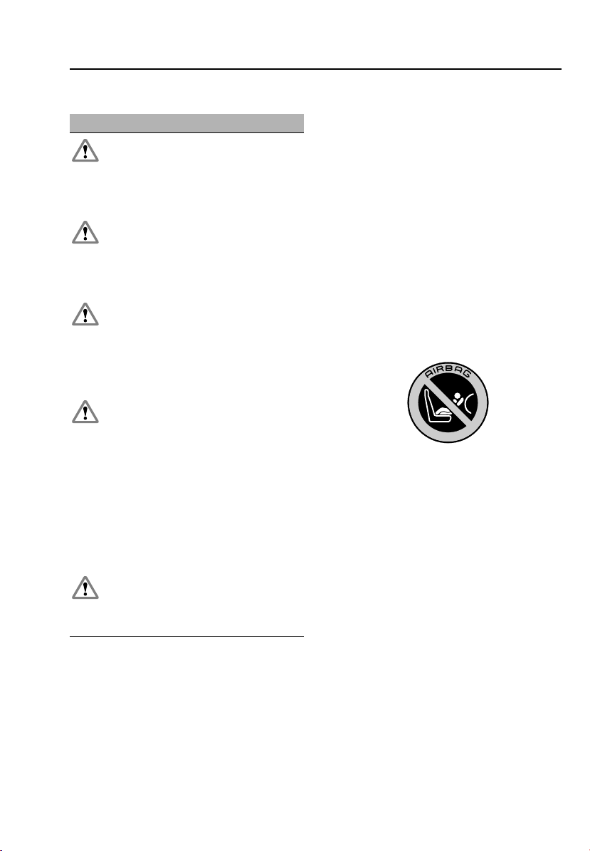
Child safety
Child safety
CHILD SEATS
WARNINGS
Do not use a child restraint on a seat
with an operational air bag in front of it.
There is a risk of death or serious injury when
the air bag deploys. The best place for a child,
is properly restrained in the rear seats.
Extreme Hazard! Do not use a rearward
facing child restraint on a seat
protected by an air bag in front of it. There is a
risk of serious injury or death when the air bag
deploys.
Do not use a forward facing child seat,
until a child is above the minimum
weight of 9 kg (20 lb.) and able to sit up
unaided. Up to the age of two, a child's spine
and neck are not sufficiently developed to
avoid injury in a frontal impact.
Do not allow a baby or infant to be held
or carried on the lap. The force of a
crash can increase effective body weight by as
much as 30 times, making it impossible to
hold on to the child. Children typically require
the use of a booster seat appropriate to their
age and size, thereby enabling the seat belts to
be properly fitted, reducing the risk of injury in
a crash. Children could be endangered in a
crash, if their child restraints are not properly
secured in the vehicle.
Do not use a child seat that hooks over
the seat back. This type of seat cannot
be satisfactorily secured and is unlikely to be
safe for your child.
The seat belts fitted to your vehicle are
designed for adults and larger children. For
their safety, it is very important that all infants
and children under 12 are restrained in a
suitable child safety seat appropriate to their
age and size.
Only fit a child seat that has been approved for
use in your vehicle, and ensure that the
manufacturer's fitting instructions are followed
exactly.
Note: Crash statistics show that children are
safer when properly restrained in the rear
seating positions than they are in the front.
If a child must travel in the front passenger
seat, Land Rover recommends the following:
1. Position the seat fully rearward.
2. Adjust the lumbar to its minimum.
3. Adjust the cushion to its highest position.
4. Set cushion rake to its lowest position.
5. Set seat belt upper anchorage to its lowest
position.
E82664
This symbol, affixed to the passenger side B
pillar of your vehicle, warns against the use of
a rear-facing child seat in the front passenger
seat when a passenger air bag is operational.
73

Child safety
Automatic locking reels (ALR)
All passenger seat belts have ALR which aids
the retention of child seats.
The procedure to install a child seat is as
follows:
1. Place the child seat in the vehicle, attach
the seat belt and secure the buckle in
accordance with the manufacturer’s fitting
instructions.
2. Pull on the shoulder section of the belt to
reel out all of the remaining webbing to the
limit of its travel. This will engage the
automatic locking feature, which then acts
as a ratchet, allowing the webbing only to
retract.
3. Allow the seat belt to retract onto the child
seat (a clicking sound will confirm that the
ratchet has engaged), while firmly pushing
the child seat into the vehicle seat.
4. Ensure that there is no slack in the seat belt
by pulling upwards on the shoulder belt
immediately above the child restraint. The
seat belt should now be locked and the
child seat held firmly in position.
When the child seat is removed and all of the
seat belt webbing is allowed to retract, the ALR
reverts to normal operation.
Note: Where possible, use the seat belt ALR to
secure large items of luggage that are to be
carried on the seats. In the event of an accident,
unsecured items become missiles capable of
causing serious injury.
Child restraints for small children and
babies
Child seats and restraint systems designed for
your vehicle will be one of two types:
• Those secured in vehicle seats by the seat
belts.
• LATCH type child restraints, employing
anchor bars built into the rear seat frame.
All new and most older type child restraint
systems incorporate a tether strap which can
be attached to an anchorage point on the
vehicle.
Child restraints for larger children
In a situation where a child is too large to fit
into a child safety seat, but is still too small to
safely fit the 3 point seat belt properly, a
booster seat is recommended for maximum
safety. Follow the manufacturer’s fitting
instructions exactly, then adjust the seat belt to
suit.
Children typically require the use of a booster
seat appropriate to their age and size, thereby
enabling the seat belts to be properly fitted,
reducing the risk of injury in a crash.
Children could be endangered in a crash if their
child restraints are not properly secured in the
vehicle.
Do not use a child seat that hooks over the seat
back. This type of seat cannot be satisfactorily
secured, and is unlikely to be safe for your
child.
74
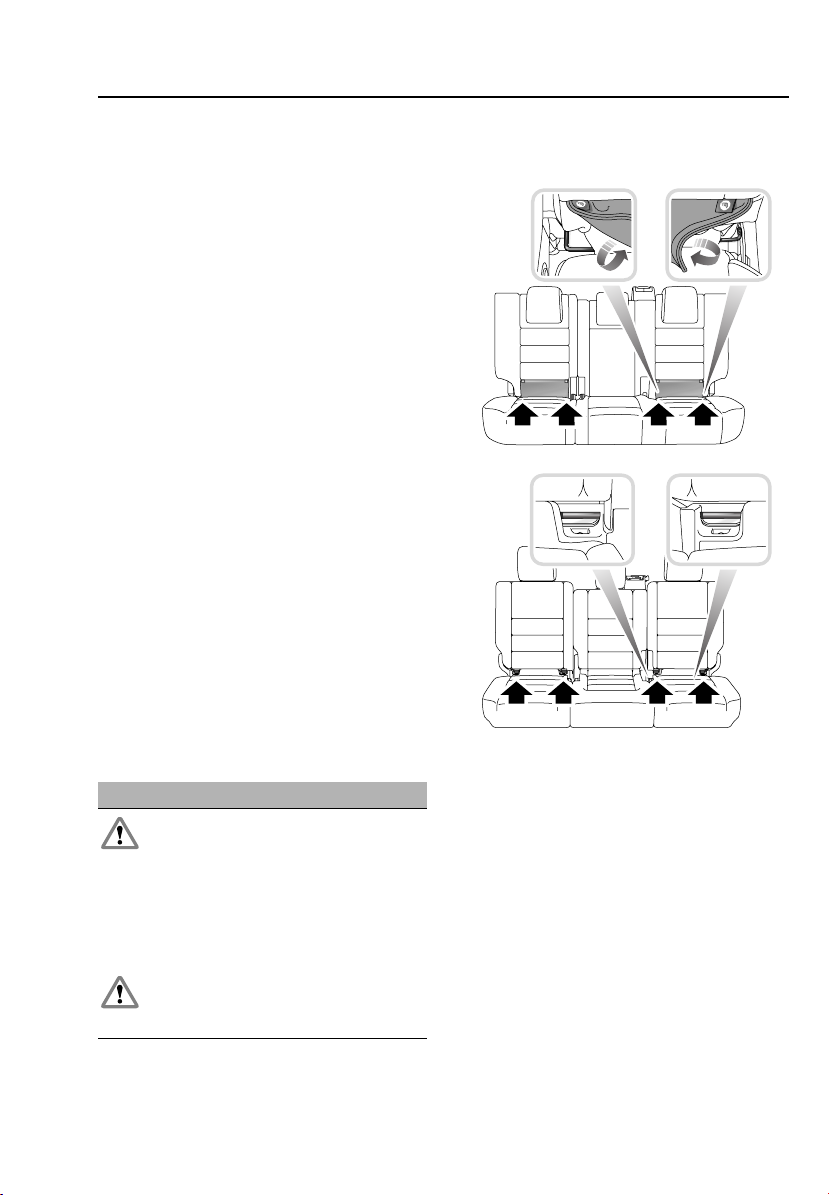
Child safety
Child restraint checklist
Complete the check list every time a child
travels in the vehicle:
• Carefully follow the instructions provided
by the manufacturer of the restraint
system.
• Always use the appropriate child restraints
and adjust harnesses for every child, every
trip.
• Always attach the top tether when
installing the LATCH seat.
• Always give the LATCH seat a final pull to
ensure that the lower anchors are secure.
• Avoid dressing a child in bulky clothing
and do not place any objects between the
child and the restraint system.
• Regularly check the fit of a child seat and
replace seats or harnesses that show signs
of wear.
• Ensure that you have removed all slack
from the adult seat belt.
• Set children a good example - always wear
your seat belt.
• Never leave a child unattended in your
vehicle.
Note: LATCH child restraints are only fitted to
the second-row seats.
A
B
LATCH ANCHOR POINTS
WARNINGS
Do not attempt to fit a LATCH child seat
to the centre seating position - the
anchor bars are not designed to hold a LATCH
child seat in this position. If the child seat is
not correctly anchored, there is a significant
risk of injury to the child in the event of a
collision or emergency braking.
Always follow the child seat or restraint
system manufacturer's instructions
when fitting tether straps.
E80614
A. 5-seat vehicles
B. 7-seat vehicles
Both second-row outer seating positions, are
equipped to accept LATCH restraints.
75
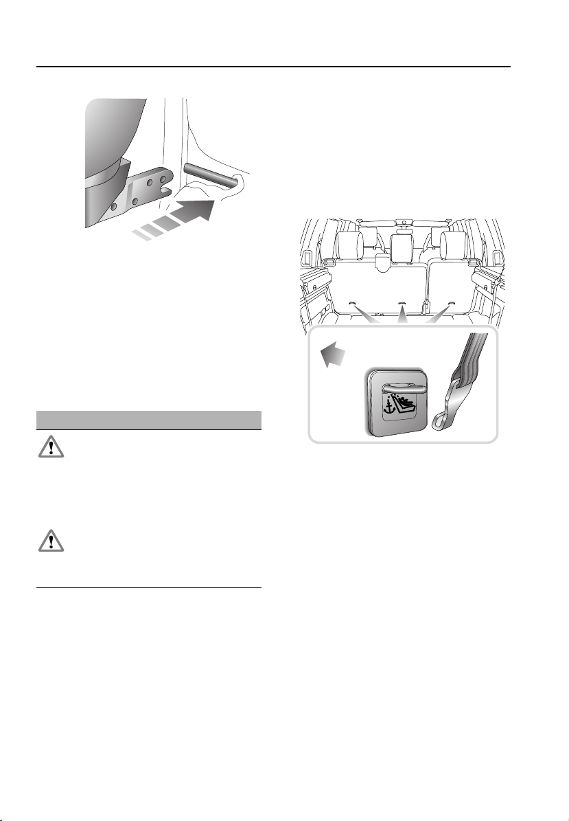
Child safety
E80615
To install your child seat with an LATCH
restraint system:
1. Raise or remove the head restraint.
2. Lift the velcro strap, exposing the LATCH
locking mechanism.
3. Slide the child seat into the locking
mechanism.
Tether strap anchorages
WARNING
Child restraint anchorages are designed
to withstand only those loads imposed
by correctly fitted child restraints. Under no
circumstances are they to be used for adult
seat belts, harnesses or for attaching other
items or equipment to the vehicle.
When fitting a child seat or restraint
system, always pass the tether strap
over the top of the seat back and beneath the
underside of the head restraint.
Upper tether anchorages are provided at each
seating position equipped to accept LATCH
child restraints (shown in the illustrations).
Note: Always ensure that if an upper tether is
provided, it is secured and tightened properly,
as this provides maximum protection for a
child.
Once the LATCH child seat is installed, test the
security of the installation, before seating a
child. Attempt to twist the child seat from side
to side and to pull it away from the vehicle seat,
then check that the anchors are still securely in
place.
Child seat upper tether anchorage
(5-seat vehicles)
FRONT OF
VEHICLE
E81521
76
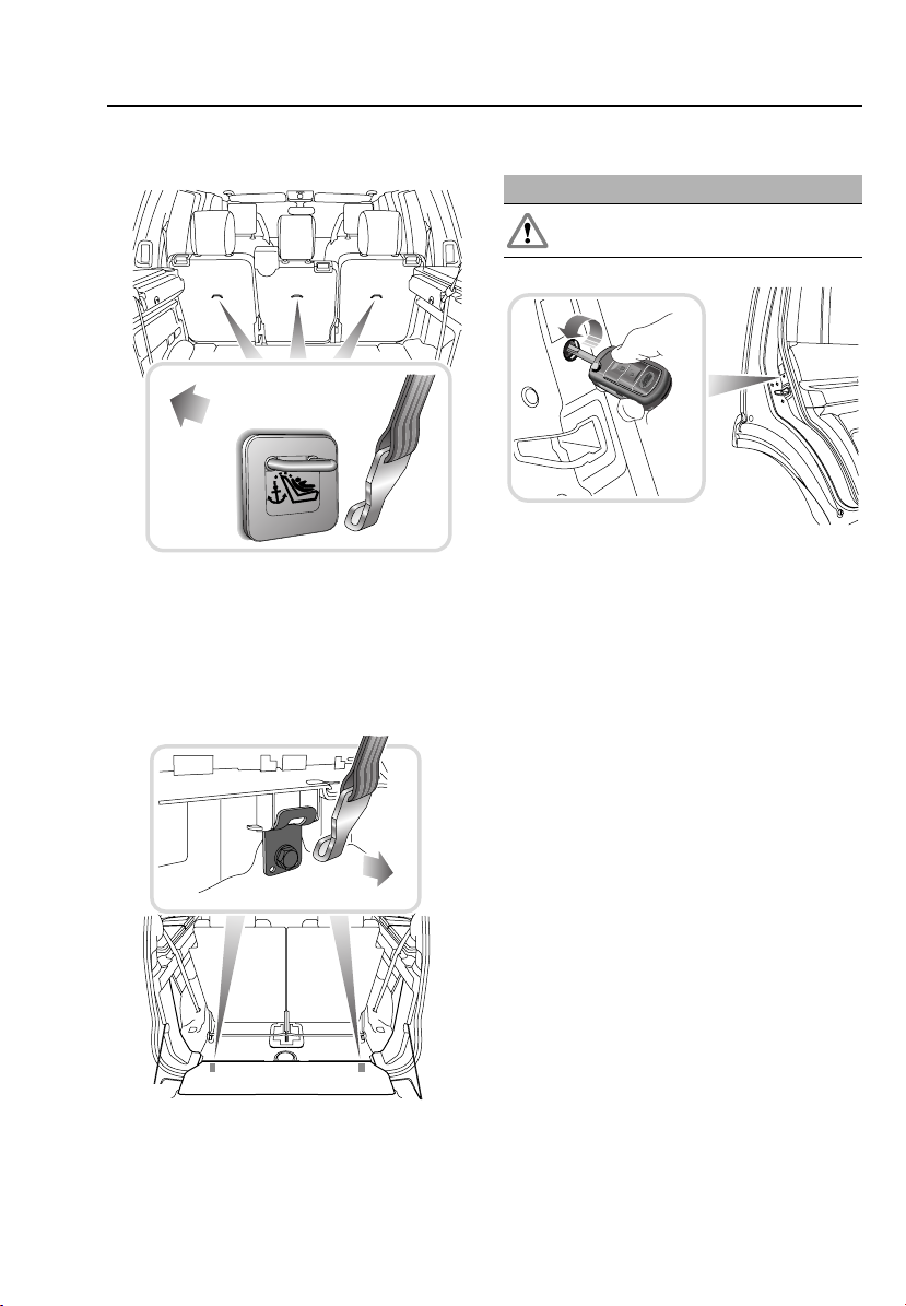
Child safety
Child seat upper tether anchorage
(7-seat vehicles)
FRONT OF
VEHICLE
E81522
Your vehicle is equipped with anchorage points
on the back of the second-row seat frames.
These should be used to attach straps from
child seats or restraint systems.
Child seat upper tether anchorage
(third-row seats)
CHILD SAFETY LOCKS
WARNING
To avoid injury or death, never leave
children unsupervised in the vehicle.
E80631
Child safety locks are fitted to the rear doors.
Insert the starter key into the keyhole and turn
outwards to activate the child safety lock.
With the child safety locks engaged, the rear
doors cannot be opened from inside the
vehicle.
Turn the key inwards to disengage the child
safety lock.
FRONT OF
VEHICLE
E82666
A tether anchorage is provided at each seating
position.
77
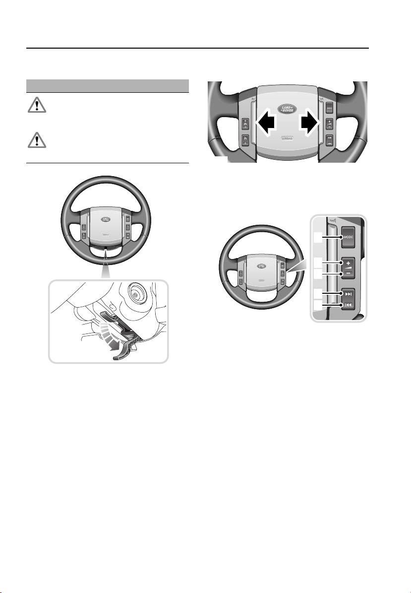
Steering wheel
Steering wheel
ADJUSTING THE STEERING WHEEL
WARNINGS
Do not adjust the steering wheel
position while the vehicle is moving.
This is extremely dangerous!
Ensure that the lever is fully up.
Inadvertent movement of the wheel
may occur if the lever is not locked.
HORN
E80445
To operate, press either of the horn switches.
AUDIO CONTROL
1
2
3
4
5
E80450
E80511
The steering wheel position can be adjusted in
two directions.
Move the lever, located under the steering
wheel, fully downwards (see inset).
Adjust the steering wheel up or down, in or out.
Move the lever fully up to lock.
1. Mode select.
2. Volume up.
3. Volume down.
4. Channel up.
5. Channel down.
78
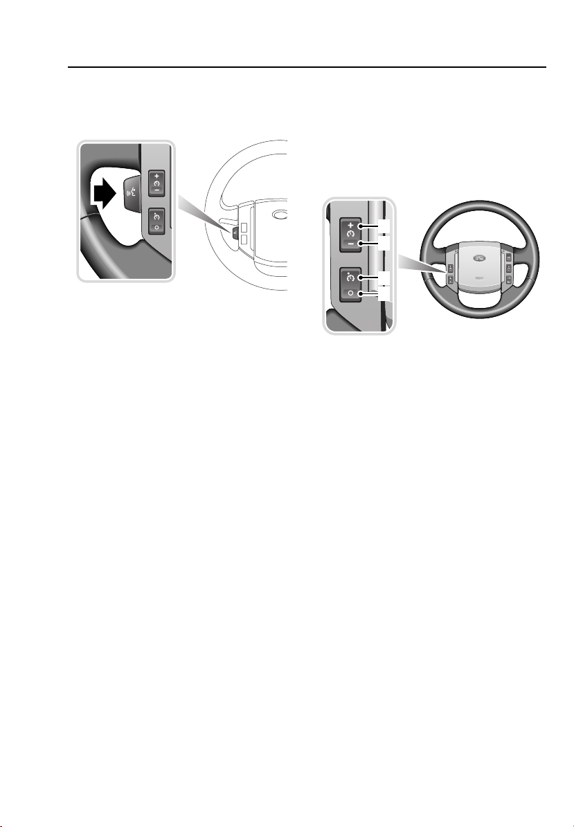
Steering wheel
VOICE RECOGNITION
Activating the voice recognition system
E80446
To activate voice recognition:
• Briefly pull the control (your audio unit will
mute at this point). An audible alert will be
heard, and LISTENING will be displayed on
the main message centre to indicate that
the system is now waiting for a voice
command.
Note: It is only necessary to use the voice
recognition control at the beginning of each
voice session.
CRUISE CONTROL
Cruise control is operated via the switches on
the steering wheel and enables the driver to
maintain a constant road speed without using
the accelerator pedal. See USING CRUISE
CONTROL (page 157).
1
2
3
4
E80444
1. Set + : Set or increase the speed.
2. Set - : Set or decrease the speed.
3. Resume: Resume set speed.
4. Cancel: Cancels without erasing
memorised speed.
79

Lighting
Lighting
GENERAL INFORMATION
There are three types of headlamp systems:
• Halogen high/low beam main lamp with a
fill-in high beam halogen lamp alongside.
• Bi-xenon high/low beam main lamps with
fill-in high beam halogen lamp alongside.
• An Adaptive Front Lighting System (AFS).
See ADAPTIVE FRONT LIGHTING SYSTEM
(AFS) (page 83).
Halogen headlamps
Halogen bulbs are very similar to the standard
light bulbs fitted to side or tail lights. Added
traces of halogen inside the bulb make it 10 to
20% more efficient than a standard light bulb
of similar voltage and wattage. Halogen bulbs
have an operating life of two to three times
longer than a standard bulb.
Bi-Xenon headlamps
Some vehicles are fitted with Xenon low/high
beam headlamp units. Xenon lamps provide
significantly improved visibility, especially
during adverse weather and driving conditions.
Bi-Xenon units use a Xenon bulb for both high
beam and low beam, whilst a halogen bulb is
used for high beam fill-in. A shutter, operated
by a solenoid, changes the direction of the
Xenon light beam, to give either low or high
beam.
The operational life of a Bi-Xenon light is
significantly longer than that of a conventional
or halogen bulb.
Daytime running lamps (Canada only)
The sidelamps, license plate lamps and
headlamp low beams will illuminate with the
engine running and the lamps master switch
turned off. The instrument pack illumination
remains off.
Unless they are required or
prohibited by law, daytime running
lamps can be disabled or enabled by
a Land Rover Dealer.
Stop lamps
The stop lamps will illuminate while the brake
pedal is pressed.
The stop lamps also illuminate when Hill
Descent Control is braking the vehicle or
during Electric parking brake dynamic
operation. See ELECTRIC PARKING BRAKE
(EPB) (page 148).
Reversing lamps
Selection of reverse gear will operate the
reversing lamps.
80

Lighting
LIGHTING CONTROL
Lamps master switch
2
1
E82950
1. Off
2. sidelamps
3. Low beam headlamps
4. Automatic control lamps
sidelamps
The sidelamps and license plate lamps,
illuminate when the lamps master switch is
turned to positions 2 or 3, regardless of the
position of the starter switch.
A green warning indicator in the
instrument pack will illuminate
when sidelamps are on.
Low beam headlamps
The low beam headlamps, illuminate when the
lamps master switch is turned to position 3,
and the starter switch is in position II.
3
4
AUTO
High beam headlamps
E81026
With the lamps master switch in position 3 and
starter switch in position II, push the column
stalk away from the steering wheel to select
high beam.
The blue warning indicator in the
instrument pack will illuminate
when high beam is selected.
To cancel high beam, pull the stalk towards the
steering wheel.
To flash the headlamps on high beam, pull the
stalk towards the steering wheel and release it.
Headlamp courtesy delay
The headlamps can be kept on for a short time
after the vehicle is parked. Turn the starter
switch off with the lamps master switch in
positions 2, or 3.
Remove the key from the starter switch and
turn the lamps master switch to position 1. The
headlamps will remain illuminated for up to
240 seconds. This time delay is configurable.
See TRIP COMPUTER (page 108).
The courtesy delay may be cancelled at any
time by turning the starter switch to position I
or II or the lamps master switch to positions 1
or 2.
Note: If Automatic Control Lamps are switched
on, the headlamp courtesy delay will operate
automatically.
81

Lighting
Automatic control lamps
With the lamps master switch in position 4 and
starter switch in position II, the sidelamps, low
beam headlamps and license plate lamps will
illuminate automatically when the ambient light
falls below a pre-defined level.
All of the lamps will go out when the ambient
light rises above that level.
FRONT FOG LAMPS
AUTO
E81028
With the sidelamps or low beam headlamps
switched on, pull the switch to position 2 to
switch on the front fog lamps.
A green warning indicator will
illuminate in the instrument pack
when the front fog lamps are
switched on.
To switch off the fog lamps, return the switch
to position 1.
Note: Fog lamps should only be used when
visibility is severely restricted.
1 2
REAR FOG LAMPS
AUTO
E81029
With the sidelamps or low beam headlamps
switched on, pull the switch to position 3 to
switch on the rear fog lamps.
If front fog lamps are not fitted, the rear fog
lamps illuminate with the switch in position 2.
An amber warning indicator will
illuminate in the instrument pack
when the rear fog lamps are
switched on.
To switch off the fog lamps, return the switch
to position 1.
Note: Fog lamps should only be used when
visibility is severely restricted.
1 2 3
82

Lighting
HAZARD WARNING FLASHERS
23
E80817
Press the switch to operate the hazard warning
lamps. All of the direction/turn indicator lamps
will flash together.
Use only in an emergency to warn other road
users when the stationary vehicle is causing an
obstruction, or is in a hazardous situation.
Remember to switch off before moving away.
ADAPTIVE FRONT LIGHTING SYSTEM
(AFS)
Adaptive front lighting system (AFS) is
designed to give the driver improved visibility.
It has two main components: A swivelling
headlamp unit and a cornering lamp, with a
beam set to 45 degrees from the centre line of
the vehicle.
The headlamp units can swivel left or right to
improve light spread on bends in the road and
they operate throughout the vehicle speed
range. They also react to braking or
acceleration in the vertical plane, to maximise
headlamp performance. Additional lighting is
supplied by the cornering lamps at speeds
between 30 km/h (18 mph) and 70 km/h (44
mph). If the higher speed is exceeded, the
cornering lamps will only reactivate when
speed reduces to 60 km/h (37 mph). These
headlamps broaden the beam of the headlamps
when cornering.
The system takes inputs from the vehicle's
road speed and steering angle, to determine
the amount of horizontal swivel. The amount of
swivel is highest at low manoeuvring speeds
and movement reduces as speed increases.
Cornering lights operate when the system
detects a steering wheel rotation of 70 degrees
or more.
If reverse gear is selected, the lamps return to
the central position and the unit's swivelling
capability is disabled.
An amber warning indicator will
illuminate in the instrument pack if a
fault is detected with the AFS. Seek
qualified assistance.
83
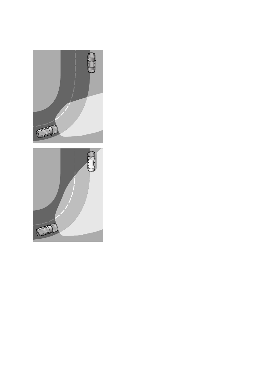
Lighting
The AFS advantage
1
2
Cornering lamps
These lamps broaden the beam of the
headlamps when cornering.
The cornering lamps have a beam set to 45
degrees outward from the centre line of the
vehicle.
The system switches on the lamp, if it has
received an input from the vehicle's
direction/turn indicator. As the system is
ignition-based, the lamps will not stay on if the
vehicle is parked with the direction/turn
indicator lever in the operating position.
Only the lamp on the same side as the
operating direction/turn indicator comes on.
Operating the direction/turn indicators will also
activate the relevant lamp.
If reverse gear is selected, the lamps return to
the central position and the unit's swivelling
capability is disabled unless the direction/turn
indicators are operating.
E80820
1. Light spread of a vehicle not fitted with
AFS.
2. Light spread of a vehicle fitted with AFS.
84

Lighting
1
2
E80821
1. Shows the light spread of a vehicle not
fitted with cornering lamps.
2. Shows the light spread of a vehicle fitted
with cornering lamps.
DIRECTION/TURN INDICATORS
E80816
With the starter switch in position II, move the
lever up or down to operate the direction/turn
indicators.
A green left or right warning
indicator in the instrument pack will
flash when the direction/turn
indicator lamps are operating.
When the lever is held momentarily up or down
against spring pressure and then released, the
indicators will flash three times to indicate a
lane change.
Note: The indicators will continue to flash if the
lever is held against spring pressure.
This feature can be enabled or
disabled by a Land Rover Dealer.
If the warning indicator fails to flash or flashes
rapidly, this may indicate a bulb failure in one
of the direction/turn indicator lamps.
85
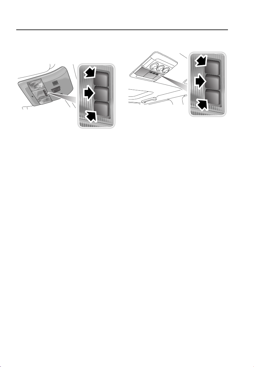
Lighting
INTERIOR LAMPS
Front interior lamps
E81079
The interior lamps can be switched on
individually by pressing the switch adjacent to
the lamp required.
It is possible to de-activate the courtesy lamps
automatic mode by pressing the centre switch.
The message INTERIOR LIGHTS OFF will flash
in the message centre.
To switch the lamps off without disabling
automatic mode briefly press the centre
switch.
To enable automatic mode press the front
centre switch for more than three seconds. The
message INTERIOR LIGHTS AUTOMATIC will
flash in the message centre.
Map lamp operation
Press the required map lamp switch (outer
lamps) to turn on and off.
Glovebox lamp
Illuminates automatically (with headlamps on)
whenever the glovebox is opened and
extinguishes when the glovebox is closed.
Rear interior lamps
E81080
The rear interior lamps are grouped together in
the roof above the second row of seats. This
fitment may include the rear air conditioning
controls.
Vanity mirror lamps
The vanity mirror lamps are turned on when the
corresponding vanity mirror cover is opened
and turned off when it is closed.
Note: Map lamps, glovebox lamps and vanity
mirror lamps will extinguish automatically after
15 minutes to prevent battery drain provided
that the starter switch is in position 0.
Low-level night-time illumination
With the main lighting switch turned to
sidelamps or headlamps, LEDs in the front
interior lamps provides very low level
illumination. The level of illumination can be
adjusted using the instrument pack
illumination dimmer switch.
Low level lighting provides very limited
illumination for the interior of the vehicle,
whilst the vehicle is being driven, without
affecting the driver’s night vision.
86

Lighting
REMOVING A HEADLAMP
Removing the grille
E80618
1. Remove the grille by pressing down on the
four upper clips, and up on the bottom
two, securing the grille to the vehicle body.
2. Lift the grille clear of the vehicle and place
it where it will not sustain any damage.
Removal of headlamp unit
11
2
E80619
1. Carefully lever up the two locking bars.
2. Disconnect the wiring plug from the back
of the unit and remove the unit from the
vehicle.
3. Place face down on a flat surface covered
in a soft material to prevent damage to the
unit's lenses.
87

Lighting
Refitting the headlamp unit
1
3
3
2
E80628
1. Reconnect the wiring plug.
2. Offer up the unit into position.
3. Push down on the two locking slides.
Refitting the grille
1. Refit the grille, aligning the upper and
lower clips with their respective slots, and
press into place.
2. Ensure the clips have sprung into place
securing the grille
REMOVING A REAR LAMP
Note: If accessory lamp guards are fitted, refer
to the separate accessory user instructions for
removal.
The rear lamp unit contains five lamps and it is
necessary to completely remove the unit from
the vehicle in order to change any of the bulbs.
Removal of rear lamp unit
1
2
1
E80591
1. With the tailgate open, remove two screws
from the edge of the unit nearer the rear
door aperture.
2. Pull the unit away from the vehicle.
3. Disconnect the wiring multi-plug and
remove the unit from the vehicle. Place
face down on a flat surface covered in a
soft material to prevent damage.
88

Lighting
1
2
3
4
5
6
E83002
Each bulb is now accessible by twisting off its
electrical connection cap. See BULB
SPECIFICATION CHART (page 98).
1. Stop/tail lamp
2. Direction/turn indicator lamp
3. Side marker lamp
4. Tail lamp
5. Reversing lamp
6. Rear fog lamp
Note: Tail lamp 3 uses the same twin-filament
bulb as stop/tail lamp 1.
Refitting the rear lamp unit
1. Reconnect the electrical multi-plug.
2. Locate the unit’s two studs in the sockets
at the outer side of the mounting face.
3. Insert and tighten the two screws on the
side of the unit nearer the door aperture.
4. Check that all of the bulbs work.
CHANGING A BULB
CAUTION
Before replacing a bulb, always turn off
the starter switch and appropriate
lighting switch to prevent any possibility of a
short circuit. Only replace bulbs with the same
type and specification. See BULB
SPECIFICATION CHART (page 98).
Check the operation of all exterior lamps before
you drive the vehicle.
Halogen bulbs
Halogen bulbs are used for high beam, low
beam and front fog lamps. Take care not to
touch this type of bulb with your fingers;
always use a cloth to handle them. If
necessary, clean the bulb with methylated
spirits to remove fingerprints.
Xenon lamp units
WARNINGS
Bi-Xenon lamp units operate at very
high temperature. If they have recently
been in use allow sufficient time for them to
cool down before touching them.
Xenon lamp units contain Mercury
which is hazardous.
The Xenon system generates up to
28,000 volts. Contact with this voltage
could lead to a fatality. Ensure that the
headlamps and starter switch are turned off
before working on the system.
Replacement or maintenance of Xenon
lamps should only be carried out by
qualified personnel.
Seek advice about the proper
disposal of Xenon lamp units from a
Land Rover Dealer or your local
authority.
89

Lighting
Headlamp unit
WARNING
Do not attempt to change any bulb with
the lighting switched on. If the lighting
has just been switched off, give the bulbs time
to cool down. Handling them in a hot condition
may cause personal injury.
The headlamp unit contains five lamps and it is
necessary to completely remove the unit from
the vehicle in order to change any of the bulbs.
See REMOVING A HEADLAMP (page 87).
Bulb access
1 2
To change a high or low beam bulb
(Halogen only)
High beam
3
2
4
E80622
Low beam
3
34
E80620
The bulbs within the headlamp unit, accessible
under domed caps are:
1. Direction/turn indicator.
2. Low beam.
3. High beam.
4. Sidelamp, front marker lamp and
cornering lamp.
4
E80623
1. Twist and lift off the domed cap.
2. Pull off the electrical connector.
3. Release the spring clip holding the bulb in
place.
4. Remove bulb.
90
2
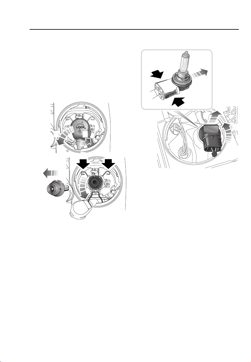
Lighting
5. Insert the new bulb and repeat the above
procedure in reverse order. When
replacing the cap, align the arrowheads on
the cap and the body of the unit.
Note: After the replacement of any high or low
beam bulb, the alignment of the headlamps
should be checked, seek qualified assistance.
To change a Xenon bulb
2
1
3
3
4
E80624
1. Twist and lift off the domed cap.
2. Twist the connector cap counterclockwise
to unlock it. Pull clear of the bulb.
3. Release the spring clip holding the bulb in
place.
4. Remove bulb.
5. Insert the new bulb and repeat the above
procedure in reverse order. When
replacing the cap, ensure that the lugs are
in contact with the bulb base.
Note: After the replacement of any high or low
beam bulb, the alignment of the headlamps
should be checked, seek qualified assistance.
To change a cornering lamp bulb
4
3
2
E80625
1. Twist and lift off the domed cap.
2. Twist the bulb holder to unlock.
3. Remove bulb complete with electrical
connector.
4. To release the bulb, squeeze the two
catches, then pull to remove the electrical
connector.
5. Insert the new bulb and repeat the above
procedure in reverse order. When
replacing the cap, align the arrowheads on
the cap and the body of the unit.
91
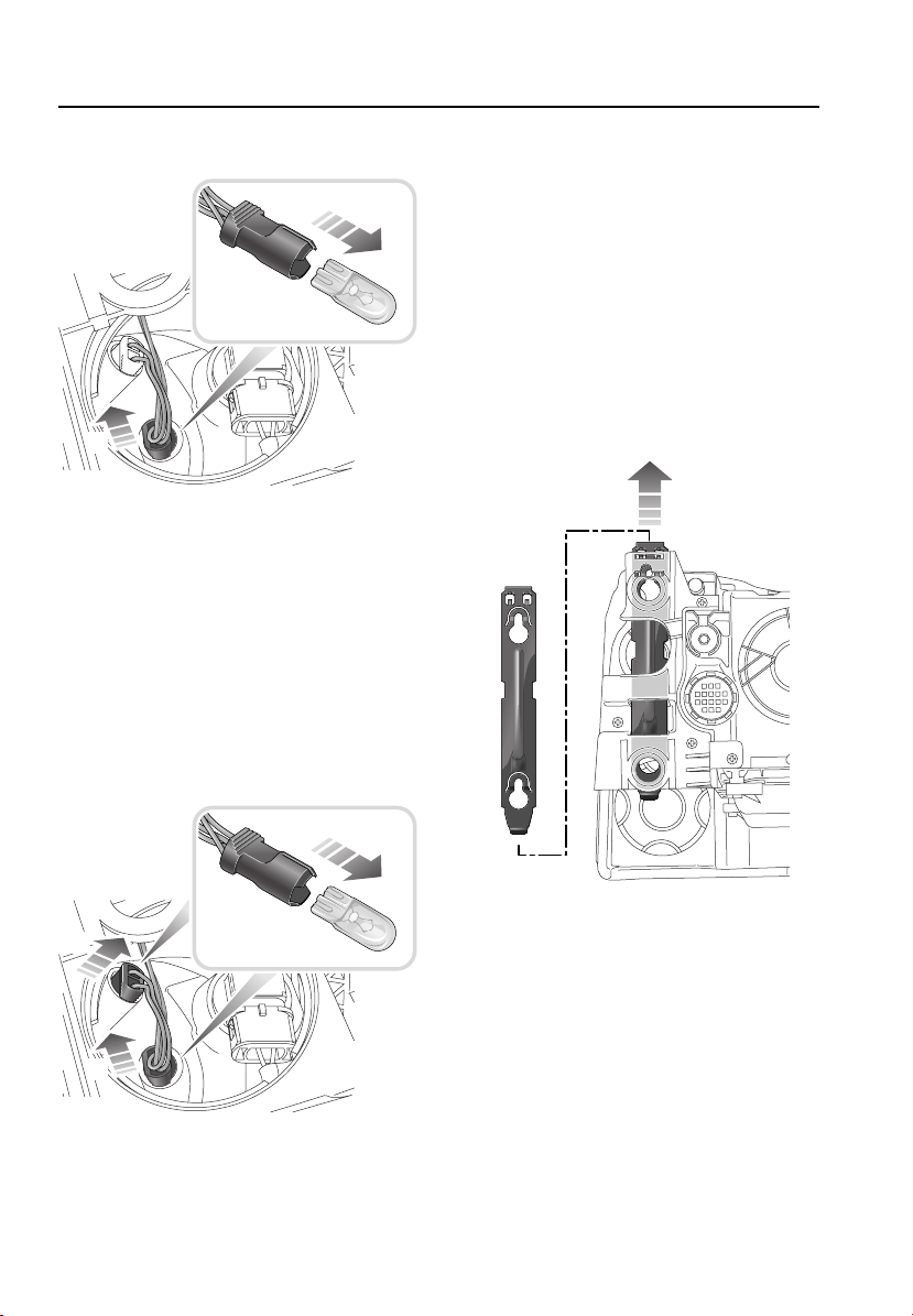
Lighting
To change a front sidelamp bulb
3
2
E80626
1. Twist and lift off the domed cap.
2. Pull out the bulb complete with electrical
connector.
3. Pull the bulb out of the electrical
connector.
4. Insert the new bulb and repeat the above
procedure in reverse order. When
replacing the cap, align the arrowheads on
the cap and the body of the unit.
To change a front marker lamp bulb
2. Pull out the bulb complete with electrical
connector.
3. Pull the bulb out of the electrical
connector.
4. Insert the new bulb and repeat the above
procedure in reverse order.
When replacing the cap, align the
arrowheads on the cap and the body of the
unit.
To change a front indicator/turn lamp
bulb
2
2
E83003
1. Twist and lift off the domed cap.
3
E80621
To access the direction/turn indicator, the
headlamp unit locking slide must be
completely removed from the unit.
92

Lighting
To change a front fog lamp bulb
3
Removing the fog lamp
1
2
2
E80627
1. Twist and lift off the domed cap.
2. Pull out the bulb complete with electrical
connector.
3. Pull the bulb out of the electrical
connector.
4. Insert the new bulb and repeat the above
procedure in reverse order. When
replacing the cap, align the arrowheads on
the cap and the body of the unit.
2
E80594
1. Using the finger slot at the top of the fog
lamp surround, pull to remove.
2. Remove the three securing screws to
release the lamp unit. Ease the unit out of
the front bumper.
2
93

Lighting
Replacing the bulb
1
2
E80595
1. Twist the bulb holder counterclockwise to
unlock, then pull out the bulb, complete
with electrical connector.
2. To release the bulb, depress the two
catches (solid arrows in inset), then pull to
remove the bulb from the holder.
3. Replace bulb. See BULB SPECIFICATION
CHART (page 98).
• Before fitting the replacement bulb, note
the flat and the tab on the otherwise
circular shape of the bulb mounting
flange. The tab acts as a key to enable
correct positioning of the bulb in the
bulb holder.
• Do not touch the bulb glass with your
fingers. If necessary, clean the bulb with
methylated spirits.
4. Insert the new bulb and repeat the above
procedure in reverse order to reassemble.
Note: After the replacement of a fog lamp bulb,
the alignment of the lamp should be checked,
seek qualified assistance.
Refitting the fog lamp
2
E80596
1. Align fog lamp to front bumper and secure
with screws.
2. Align the spring clip above the finger slot
with the upper receiver shape in the
bumper and push into place.
3. Push the lower part of fog lamp surround
into place, applying some upward
pressure.
Note: The fog lamp surround is uniquely
shaped and will only fit in one position.
94

Lighting
To change a license plate lamp bulb
2
3
1
E81086
1. With the upper tailgate open, use a suitable
tool to lever the lens from the tailgate (see
inset).
2. Twist the bulb holder counterclockwise to
unlock, then pull out the bulb, complete
with electrical connector.
3. Pull the bulb to remove it from the
connector.
4. Insert a new bulb and refit the
components. See BULB SPECIFICATION
CHART (page 98).
To change a side repeater lamp bulb
1
2
3
E81087
1. Push the lens firmly towards the front of
the vehicle and withdraw the lamp unit
from the wing.
2. Twist to release the bulb holder from the
lens unit.
3. Pull the bulb to remove it from the
connector.
4. Insert a new bulb and refit the
components. See BULB SPECIFICATION
CHART (page 98).
95

Lighting
To change a stepwell lamp bulb
1
2
E80597
1. With the relevant door open, insert a small
flat-bladed screwdriver under the forward
edge of the lens, to carefully lever the lamp
unit out.
2. Pull the bulb out of the electrical
connector.
3. Insert a new bulb and refit the
components. See BULB SPECIFICATION
CHART (page 98).
To change a courtesy lamp bulb
1
2
E81088
1. Insert a small flat-bladed screwdriver into
the indent on the side of the lens and
carefully prise the lens from the lamp unit.
2. Pull the bulb out of the electrical
connector.
3. Insert a new bulb and refit the
components. See BULB SPECIFICATION
CHART (page 98).
96

Lighting
To change a tailgate lamp bulb
1
2
E80597
1. Insert a small flat-bladed screwdriver
under the lens and carefully prise the lens
from the lamp unit.
2. Pull the bulb out of the electrical
connector.
3. Insert a new bulb and refit the
components. See BULB SPECIFICATION
CHART (page 98).
To change a map lamp bulb
1
2
E81089
1. Insert a small flat-bladed screwdriver into
the indent on the side of the lens and
carefully prise the lens from the lamp unit.
2. Pull the bulb out of the electrical
connector.
3. Insert a new bulb and refit the
components. See BULB SPECIFICATION
CHART (page 98).
97
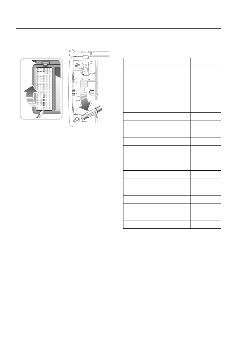
Lighting
To change a vanity mirror lamp bulb
2
1
E81090
1. With the vanity mirror cover open, use a
small flat-bladed screwdriver to carefully
lever the relevant lens from the
mirror/lamp unit.
2. Pull the bulb out of the electrical
connector.
3. Insert a new bulb and refit the
components. See BULB SPECIFICATION
CHART (page 98).
BULB SPECIFICATION CHART
Note: All bulbs must be rated at 12 volts.
Bulb Watts
Headlamps, low and high beam
(Halogen)
Headlamps, low and high beam
(Xenon)
Cornering lamps (Halogen) 35 (H8)
Front side and marker lamps W5W
Front direction/turn indicators S8
Rear direction/turn indicators P21
Front fog lamps (Halogen) 55 (H11)
Side marker lamps W5W
Reverse lamps P21
Rear fog guard lamps P21
Stop/tail lamps P21/5
License plate lamps W5W
Door/puddle lamps W5W
Interior lamps W5W
Luggage/footwell lamps W5W
Luggage/tailgate lamps W5W
Glovebox lamp W5W
Vanity mirror lamp 1.2
55 (H7)
55 (D2S)
Note: In certain territories it is a legal
requirement to carry spare bulbs, in case of
bulb failure. A replacement bulb kit is available
as an approved accessory from your Land
Rover Dealer.
98

Wipers and washers
Wipers and washers
WINDSHIELD WIPERS
The wipers and washers will only operate when
the starter switch is turned to position I or II.
CAUTIONS
Do not operate the windshield wipers on
a dry screen. The drag on the wiper
mechanism may cause damage.
In freezing or very hot conditions ensure
that the wipers have not stuck to the
windshield before operating. The drag on the
wiper mechanism may cause damage.
Remove any snow, ice or frost, from the
windshield, around the wiper arms and
blades, and the screen scuttle before operating
the wipers. Snow and ice can cause damage to
the wiper mechanism if left uncleared.
Note: If the wiper blades do become stuck, or
jammed, an electronic cut out may temporarily
halt the operation of the wipers. If this
happens, switch off the wipers and the starter
switch. Clear any obstructions, and free the
wiper blades before attempting to turn the
starter switch on.
3
2
1
0
4
E80468
1. Rain sensor or intermittent variable delay
2. Normal speed wipe
3. Fast speed wipe
Single wipe
Pull the lever down to position 4 and release
immediately.
Note: With the lever held down, the wipers will
operate at fast speed until the lever is released.
Intermittent variable delay
E80469
With the lever in position 1, rotate the collar
clockwise to decrease the interval between
wipes. Rotate the collar counterclockwise to
increase the interval between wipes.
Speed dependent mode
When speed dependent mode is configured,
the operation of all wiper modes will be
affected by vehicle speed.
If the vehicle’s speed drops below 8 km/h
(5 mph) with the wipers operating, the wiper
frequency automatically reduces. The wipers
will switch to the next lowest speed. When the
vehicle’s speed increases to over 8 km/h
(5 mph), the original wiper speed setting is
restored automatically.
This feature can be enabled or
disabled by a Land Rover Dealer.
99
 Loading...