


Rover DEFENDER 2006 Owner Manual

OWNER’S HANDBOOK
Publication Part No. LRL 21 02 51 601
© Land Rover 2005

Introduction
This handbook covers current versions of the Land Rover Defender models and, together with other
books in your literature pack, provides all of information that you need to derive maximum pleasure
from owning and driving your new vehicle.
For your convenience, the handbook is divided into sections, each dealing with a different aspect of
the vehicle. These are listed on the Contents page and you will find it worthwhile to take a little time
to read each one, and get to know your Defender as soon as you possibly can. The more you
understand before you drive, the greater the satisfaction once you are seated behind the steering
wheel.
The specification of each vehicle will vary according to territorial requirements and also from model
to model within the vehicle range. Some of the information published in this handbook, therefore,
may not apply to your particular vehicle.
To include changes made after the handbook is printed, it is sometimes necessary to issue one or
more handbook supplements.
Any further updates will be posted on the Land Rover internet site and can be accessed at
www.ownerinfo.landrover.com
* An asterisk appearing within the handbook text identifies features or items of equipment that
are either optional, or are only fitted to some vehicles in the model range.
Land Rover operates a policy of constant product improvement and therefore reserves the right to
change specifications without notice at any time. Whilst every effort is made to ensure complete
accuracy of the information in this handbook, no liabilities for inaccuracies or the consequences
thereof can be accepted by the manufacturer or the dealer, except in respect of personal injury
caused by the negligence of the manufacturer or the dealer.
All rights reserved. No part of this publication may be reproduced, stored in a retrieval system or
transmitted, in any form, electronic, mechanical, photocopying, recording or other means without
prior written permission from the Service Division of Land Rover.
As part of Land Rover environmental policy, this publication is printed on paper made from chlorine free pulp.
2

Contents
Quick Overview
Controls . . . . . . . . . . . . . . . . . . . . . . . . . . .5
Fascia Switches . . . . . . . . . . . . . . . . . . . . .6
Instrument Panel . . . . . . . . . . . . . . . . . . . .7
Warning Indicators . . . . . . . . . . . . . . . . . . .8
Lamps and Indicators . . . . . . . . . . . . . . . . .9
Wipers and Washers . . . . . . . . . . . . . . . . .10
Heating and Ventilation . . . . . . . . . . . . . . .11
Audio System . . . . . . . . . . . . . . . . . . . . . . 14
Filling Station Information
Fuel Filler . . . . . . . . . . . . . . . . . . . . . . . . . 15
Fuel Type . . . . . . . . . . . . . . . . . . . . . . . . . 15
Bonnet Opening . . . . . . . . . . . . . . . . . . . . 15
Engine Oil . . . . . . . . . . . . . . . . . . . . . . . . . 15
Engine Coolant . . . . . . . . . . . . . . . . . . . . . 15
Tyre Pressures . . . . . . . . . . . . . . . . . . . . . 16
General Information
Warnings . . . . . . . . . . . . . . . . . . . . . . . . .17
Warning Labels . . . . . . . . . . . . . . . . . . . . .18
Controls and Instruments
Keys and Remote Controls . . . . . . . . . . . . 19
Fascia Controls . . . . . . . . . . . . . . . . . . . . .20
Locks and Alarms . . . . . . . . . . . . . . . . . . .22
Seats . . . . . . . . . . . . . . . . . . . . . . . . . . . . .31
Seat Belts . . . . . . . . . . . . . . . . . . . . . . . . .38
Child Restraints . . . . . . . . . . . . . . . . . . . .41
Door Mirrors . . . . . . . . . . . . . . . . . . . . . . .43
Instruments . . . . . . . . . . . . . . . . . . . . . . .44
Warning Indicators . . . . . . . . . . . . . . . . . .45
Lamps and Indicators . . . . . . . . . . . . . . . .48
Wipers and Washers . . . . . . . . . . . . . . . . .51
Manual Windows . . . . . . . . . . . . . . . . . . .53
Electric Windows . . . . . . . . . . . . . . . . . . .54
Sunroof . . . . . . . . . . . . . . . . . . . . . . . . . . .55
Heating and Ventilation . . . . . . . . . . . . . . .56
Air Conditioning . . . . . . . . . . . . . . . . . . . .60
Interior Equipment . . . . . . . . . . . . . . . . . .62
Exterior Equipment . . . . . . . . . . . . . . . . . .66
Driving and Operating
Starting and Driving . . . . . . . . . . . . . . . . .67
Catalytic Converter . . . . . . . . . . . . . . . . . .72
Fuel and Refuelling . . . . . . . . . . . . . . . . . .73
Manual Gearbox . . . . . . . . . . . . . . . . . . . .77
Transfer Gearbox . . . . . . . . . . . . . . . . . . .78
Brakes . . . . . . . . . . . . . . . . . . . . . . . . . . . . 81
Traction Control . . . . . . . . . . . . . . . . . . . .84
Towing . . . . . . . . . . . . . . . . . . . . . . . . . . .85
Cab Pick-up . . . . . . . . . . . . . . . . . . . . . . .89
Load Carrying . . . . . . . . . . . . . . . . . . . . . .94
Ancillary Equipment . . . . . . . . . . . . . . . . .95
Off-road Driving
Off-road Driving . . . . . . . . . . . . . . . . . . . .97
Driving Techniques . . . . . . . . . . . . . . . . .101
3

Contents
Owner Maintenance
Maintenance . . . . . . . . . . . . . . . . . . . . . .109
Bonnet Opening . . . . . . . . . . . . . . . . . . .112
Engine Compartment . . . . . . . . . . . . . . .113
Engine Oil . . . . . . . . . . . . . . . . . . . . . . . .115
Cooling System . . . . . . . . . . . . . . . . . . . .116
Fuel System . . . . . . . . . . . . . . . . . . . . . .118
Brakes . . . . . . . . . . . . . . . . . . . . . . . . . . .119
Clutch . . . . . . . . . . . . . . . . . . . . . . . . . . .120
Power Steering . . . . . . . . . . . . . . . . . . . .121
Washers . . . . . . . . . . . . . . . . . . . . . . . . .122
Wiper Blades . . . . . . . . . . . . . . . . . . . . . .124
Battery . . . . . . . . . . . . . . . . . . . . . . . . . . .125
Tyres . . . . . . . . . . . . . . . . . . . . . . . . . . . .128
Cleaning and Vehicle Care . . . . . . . . . . . .131
Identification Numbers . . . . . . . . . . . . . .133
Parts and Accessories . . . . . . . . . . . . . . .134
Emergency Information
Wheel Changing . . . . . . . . . . . . . . . . . . .135
Emergency Starting . . . . . . . . . . . . . . . . .143
Towing the Vehicle . . . . . . . . . . . . . . . . .145
Fuses . . . . . . . . . . . . . . . . . . . . . . . . . . . .147
Bulb Replacement . . . . . . . . . . . . . . . . . .151
Technical Data
Lubricants and Fluids . . . . . . . . . . . . . . .155
Capacities . . . . . . . . . . . . . . . . . . . . . . . .157
Engines . . . . . . . . . . . . . . . . . . . . . . . . . .158
Electrical and Steering . . . . . . . . . . . . . . .159
Wheels and Tyres . . . . . . . . . . . . . . . . . .160
Dimensions . . . . . . . . . . . . . . . . . . . . . . .163
Weights . . . . . . . . . . . . . . . . . . . . . . . . . .168
Towing Weights . . . . . . . . . . . . . . . . . . .170
Fuel Consumption . . . . . . . . . . . . . . . . . .171
Appendices . . . . . . . . . . . . . . . . . . . . . . .172
Audio System
Radio Reception . . . . . . . . . . . . . . . . . . 175
Care of Cassette Player and Tapes . . . . 176
Care of Compact Discs . . . . . . . . . . . . . 177
Security Code . . . . . . . . . . . . . . . . . . . . 178
C42 Radio . . . . . . . . . . . . . . . . . . . . . . . 181
C42 - Radio Tuning . . . . . . . . . . . . . . . . 184
C42 - Traffic & News Information . . . . . 187
C42 - Cassette Player . . . . . . . . . . . . . . 189
C42 - Compact Disc Player . . . . . . . . . . 190
Visteon Radio . . . . . . . . . . . . . . . . . . . . 191
Visteon - Radio Tuning . . . . . . . . . . . . . 195
Visteon - Radio Data System . . . . . . . . . 198
Visteon - Traffic & News Information . . 203
Visteon - Compact Disc Player . . . . . . . 206
CD Changer Unit . . . . . . . . . . . . . . . . . . 209
Conformance . . . . . . . . . . . . . . . . . . . . . 211
#
Quick Overview
Quick Overview
CONTROLS
Quick Overview
5
6
H4959
4
12
39
6
LAND -
- ROVER
100
80
120
km/h
60
140
160
40
20
180
0
200
7
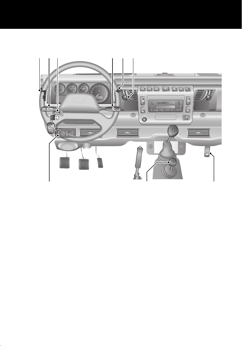
1. Fresh air vent control
2. Air blower control
3. Windscreen wiper/washer control
4. Lamps master switch
5. Direction indicators and horn control
2
3
1
8
9
6. Air temperature & distribution controls
7. Air conditioning controls
*
8. Transfer gear lever
9. Bonnet release lever
NOTE: The precise specification and location of the controls may vary according to territorial
requirements and from model to model within the vehicle range.
NOTE: For further information on the controls, see ‘FASCIA CONTROLS’, page 20.
5
FASCIA SWITCHES
Quick Overview
1 2 3 4 5 6
7
8
H4963
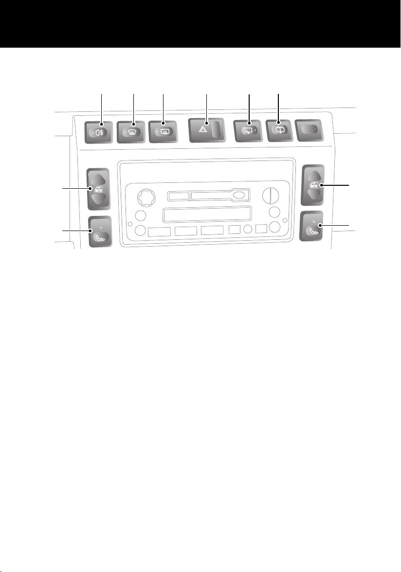
1. Rear fog lamps*
Press to operate (see ‘FOG LAMPS*’,
page 50)
2. Heated front screen
Press to operate (see ‘HEATED FRONT
SCREEN AND REAR WINDOW*’, page 59)
3. Heated rear window
Press to operate (see ‘HEATED FRONT
SCREEN AND REAR WINDOW*’, page 59)
4. Hazard warning lamps
Press to operate (‘HAZARD WARNING
LAMPS’, page 50)
5. Rear window wiper
Press to operate (see ‘REAR WINDOW
WIPER AND WASHER*’, page 52)
*
*
*
6. Rear window washer
Press to operate (see ‘REAR WINDOW
WIPER AND WASHER*’, page 52)
7. Electric windows
Press the appropriate switch to operate
the front left or right window (see
‘ELECTRIC WINDOWS *’, page 54)
8. Seat heaters
Press the appropriate switch to operate
the front left or right seat heater (see
‘HEATED FRONT SEATS*’, page 33)
*
*
*
7
8
6
INSTRUMENT PANEL
Quick Overview
12
39
6
120
km/h
H4965
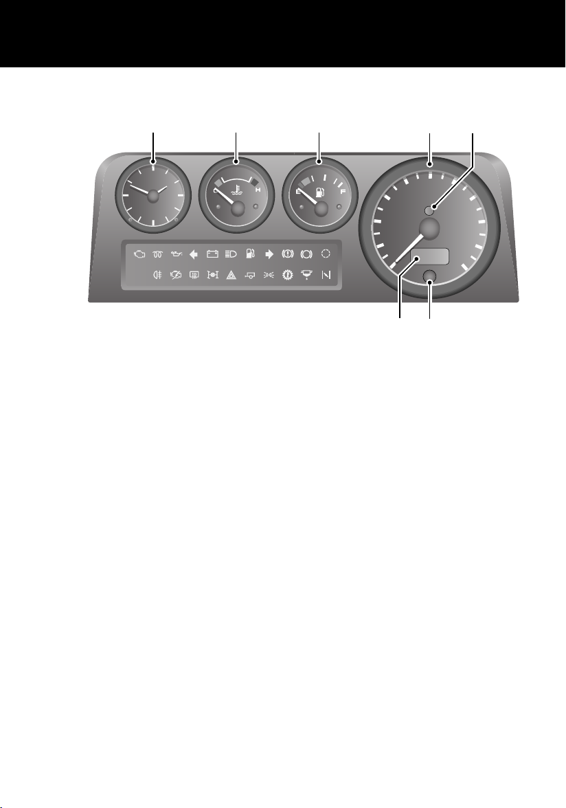
1. Speedometer
2. Engine immobilisation warning indicator
3. Total distance (odometer) and trip
recorder
4. Trip recorder reset button
567
40
ABS
TC
5. Fuel gauge
NOTE: When the fuel remaining drops to a
minimum of 9 litres, the low fuel warning
indicator will illuminate (see ‘INDICATOR
GROUPING’, page 45).
1
100
80
km/h
60
20
0
3
4
2
120
140
160
180
200
6. Temperature gauge
7. Clock
NOTE: For further information on the instrument panel, see ‘INSTRUMENT PANEL’, page 44.
7

WARNING INDICATORS
Quick Overview
4
ABS
TC
120
km/h
1 2 3
5
H5333
1. Low oil pressure (Red)
2. Battery charging (Red)
3. Handbrake (Red)
NOTE: If a warning indicator remains on or illuminates while driving, stop the vehicle and refer to the
relevant section of this handbook for advice.
NOTE: For further information on the warning indicators, see ‘INDICATOR GROUPING’, page 45.
4. Anti-lock braking system (Amber)*
5. Transmission oil temperature (Red)*
8
Quick Overview
LAMPS AND INDICATORS
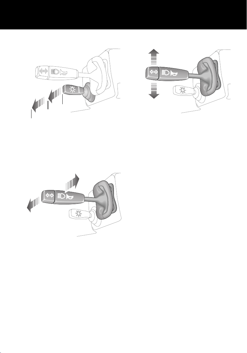
0
1
2
H3632
1. Side, tail and instrument panel lamps
2. Headlamps
Headlamp main and dipped beams
Direction indicators
H3629
Move the lever DOWN to indicate a LEFT turn,
and UP to indicate a RIGHT turn.
NOTE: For further information concerning
operation of the lamps and indicators, please
refer to ‘LAMPS’, page 48 and ‘DIRECTION
INDICATORS’, page 48.
H3630
Push the lever away from the steering wheel to
change headlamp beams.
To flash the headlamps, pull the lever part way
towards the steering wheel and release.
9
Quick Overview
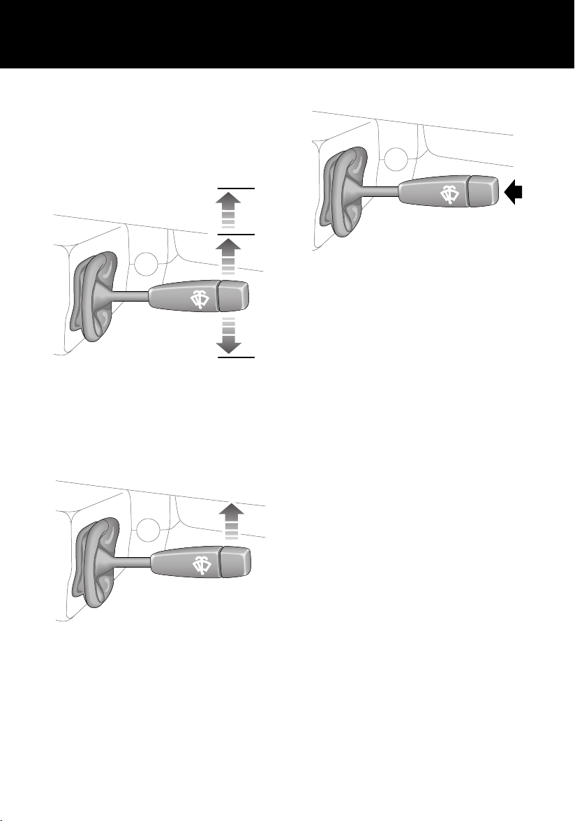
WIPERS AND WASHERS
The wipers and washers will only operate when
the starter switch is turned to position ‘I’ or ‘II’.
Windscreen wipers
3
2
H4969
1. Intermittent wipe
2. Normal speed wipe
3. Fast speed wipe
Single wipe
1
Windscreen washer
H3628
Press to operate.
NOTE: For further information concerning
operation of the wipers and washers, see
‘WINDSCREEN WIPERS’, page 51
and‘WINDSCREEN WASHER’, page 52.
H3626
Push the lever up against spring pressure and
release immediately.
10
Quick Overview
USING YOUR HEATER
3
2
H4970
Maximum heating
• Air blower control (1) - fully down.
• Air distribution control (2) - midway.
• Temperature control (3) - fully down.
Demisting and defrosting
• Air blower control (1) - fully down.
• Air distribution control (2) - fully up.
• Temperature control (3) - fully down.
Maximum ventilation
• Air blower control (1) - fully down.
• Air distribution control (2) - fully down.
• Temperature control (3) - fully up.
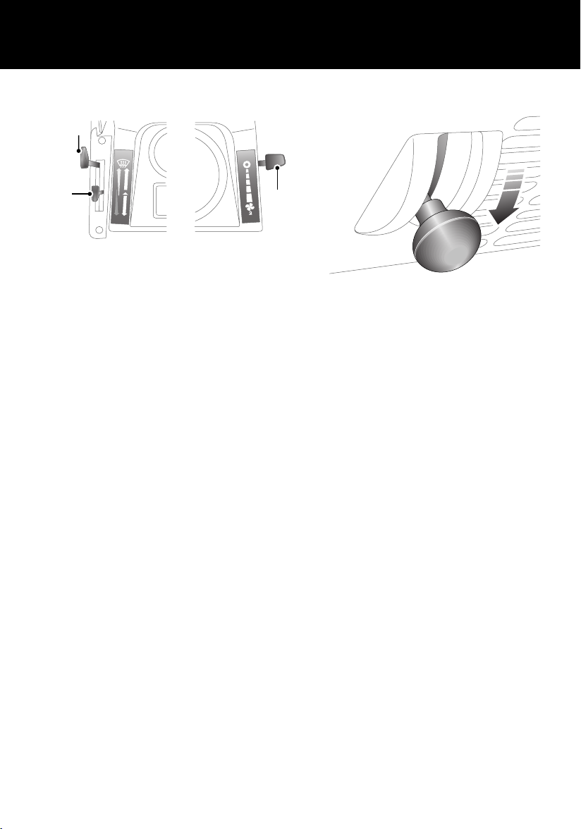
Fresh air vents
1
H3719
To open a vent, pull the knob out and push the
levers downwards.
NOTE: For further information concerning
heater controls, see ‘HEATER CONTROLS’,
page 57.
11
Quick Overview
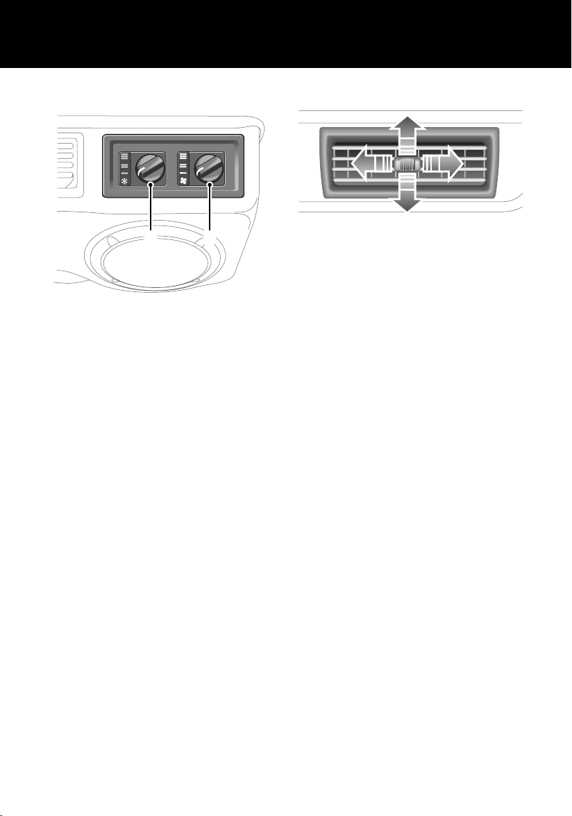
AIR CONDITIONING CONTROLS*
2
H3684
1. On/off blower control
2. Temperature control
1
Air conditioning vents
H3756
The adjuster in the centre of each vent can be
used to adjust volume and direction of air. To
cut off the supply of air from any particular
vent, slide the adjuster fully to the left.
NOTE: For further information concerning
heater controls, see ‘HEATER CONTROLS’,
page 57.
12
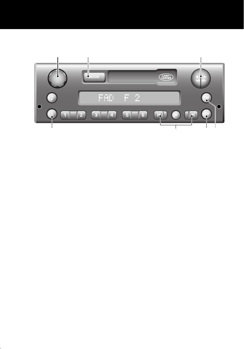
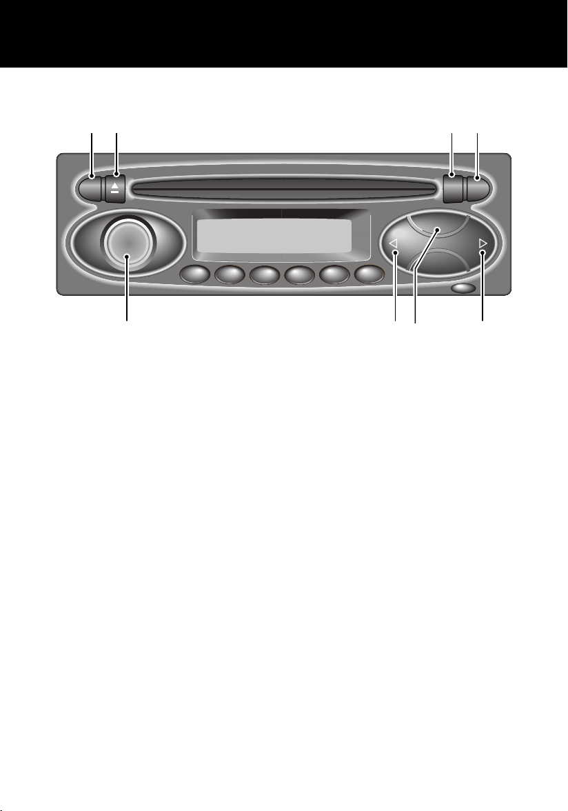
AUDIO SYSTEM CONTROLS*
1 2 3
Quick Overview
7
H4986
1. On/off volume control
2. Mode selector (MODE)
3. Tape controls
4. FM selector
NOTE: For more information concerning the operation of your audio system, see ‘AUDIO SYSTEM’,
page 175.
5. AM selector
6. Scan buttons
7. Traffic and news information
6
5 4
13
Quick Overview
AUDIO SYSTEM WITH CD PLAYER CONTROLS*
162 3 4
RDS
FADE
BAL
BASS
TREB
1
2
34
i
CD
BAND
6
5
MENU
ICE1398
1. Radio Data System (RDS) selector
2. CD eject control
3. CD mode/repeat selector
4. Traffic and news information
5. Search controls
6. Waveband selector
7. Search controls
8. On/off and volume control
7 58
For more information concerning the operation of your audio system, see ‘AUDIO SYSTEM’,
page 175.
NOTE: Some music CD manufacturers are using data encryption to 'copy-protect' their recordings
and prevent the production of pirate copies. These CDs differ from the internationally agreed CD
audio standard, RedBook, a standard that serves as the operating basis for all CD players and
changers.
Copy-protected CDs may not play in your Audio unit or CD changer or may be played subject to
various limitations, e.g. sound quality may be impaired.
If you do experience a problem, try the CD in other players before contacting the CD vendor.
14
Filling Station Information
Filling Station Information
Filling Station Information
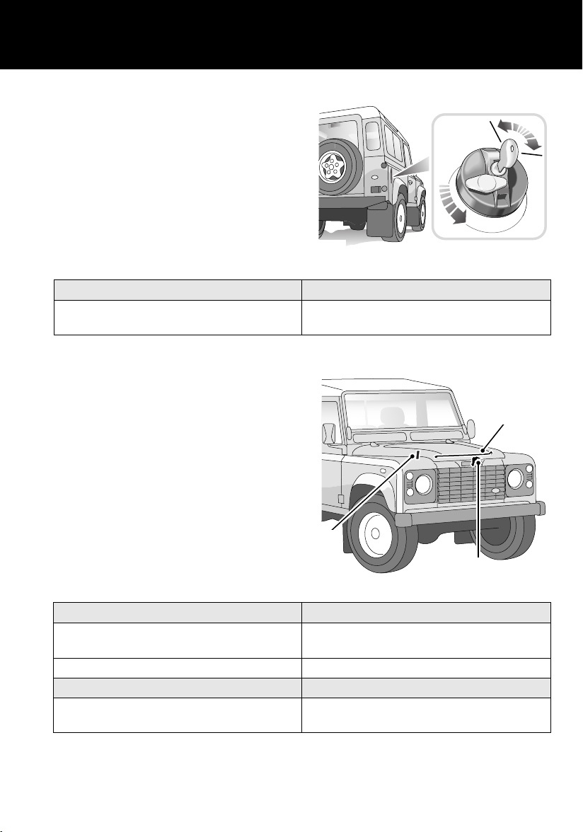
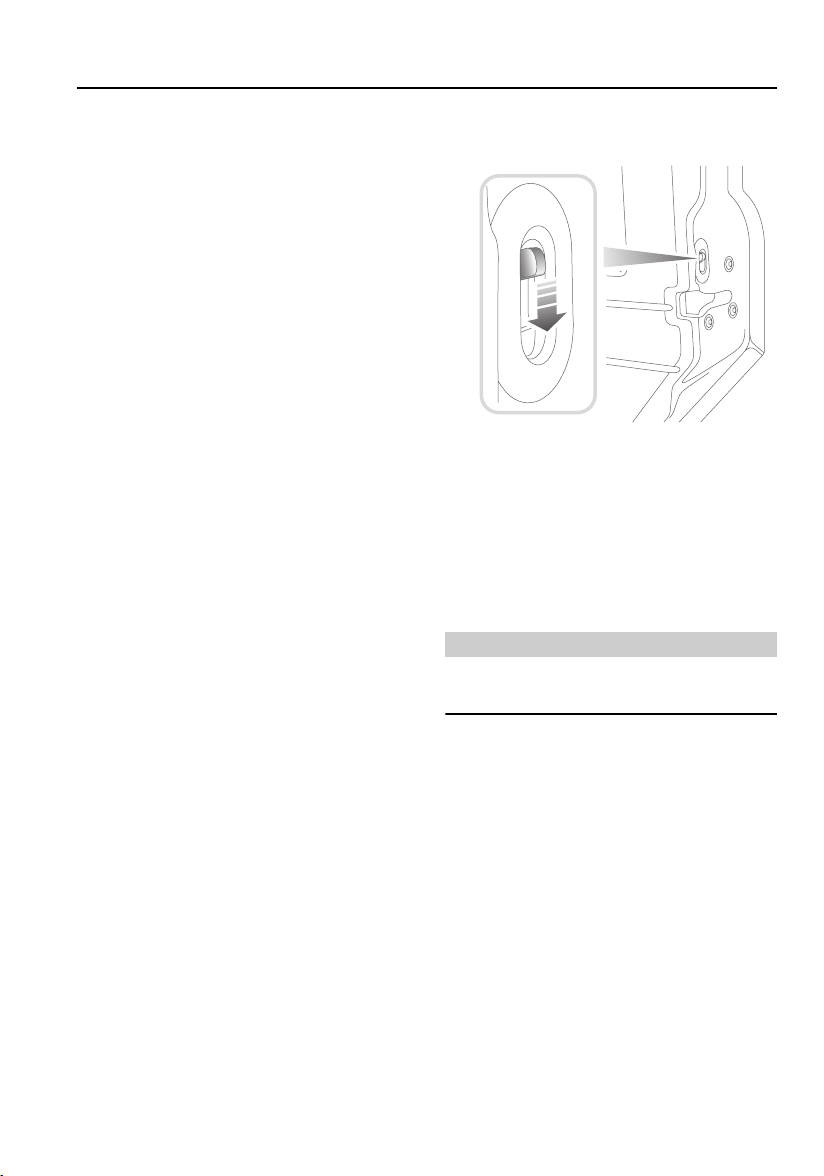
Fuel Filler
The fuel filler is located in the rear right-hand
body side.
Insert the key in the lock, turn it 90o clockwise
and allow any pressure inside the tank to
escape, before removing the cap.
NOTE: To replace the cap, the key should be
removed from the filler cap. The cap should be
turned clockwise until the ratchet is heard to
click at least three times. The cap is then locked.
Fuel type
All vehicles Diesel to EN 590 specification.
Opening the bonnet
Ensure that wipers are switched off and parked.
1. From inside the vehicle, pull the bonnet
release handle located on the right hand
side of the fascia at knee height.
2. Lift the bonnet safety catch lever.
3. Raise the bonnet and support it on the
stay.
H5253
NOT compatible with Bio-Diesel fuels
3
1
H5252
Engine oil top up
Td5 engines Castrol 5W/30 oil to ACEA: A1 and B1
specification.
Tdi engines Castrol 10W/40 oil to ACEA: B2 specification.
Cooling system top up
All vehicles 50% mix of fresh water and Castrol Anti-freeze
SF or Texaco XLC.
15
2

Filling Station Information
Tyre pressures
Air pressure naturally increases in warm tyres (after the vehicle has been driven for a while). if you
have to check warm tyres, you should expect the pressures to have increased between 30 and 40 kPa
(4 and 6 lbf/in2). In this circumstance, NEVER let air out of the tyres in order to match the
recommended pressures.
All loading conditions
90 Models Front 197 (28)
Rear 262 (38)
110 Models Front 197 (28)
Rear 338 (48)
130 Models Front 309 (44)
Rear 457 (65)
Goodyear G90 750 R16C
10 ply rating radial
Front 220 (32)
Rear 410 (60)
Pressure - kPa (lbf/in2)
16

General Information
General In formati on
WARNINGS IN THIS HANDBOOK
WARNING
Safety warnings are included in this
handbook. These indicate either a procedure
which must be followed precisely, or
information that should be considered with
great care, in order to avoid the possibility of
personal injury or serious damage to the
vehicle.
HANDLING CHARACTERISTICS
WARNING
Your vehicle has a higher ground clearance
and, hence, a higher centre of gravity than
ordinary passenger cars. This will result in
different handling characteristics.
Inexperienced drivers should take additional
care, particularly in off-road driving
situations and when performing abrupt
manoeuvres on unstable surfaces.
SYMBOLS USED
The following symbols used within the
handbook call your attention to specific types of
information.
This recycling symbol identifies those
items that must be disposed of safely in
order to prevent unnecessary damage to the
environment.
*An asterisk appearing within the text,
identifies features or items of equipment that
are either optional, or are only fitted to some
vehicles in the model range.
17
General Information
WARNING LABELS ATTACHED TO THE
VEHICLE
Warning labels attached to your vehicle
bearing this symbol mean: DO NOT
touch or adjust components until you
have read the relevant instructions in
the handbook.
Warning labels showing this symbol
indicate that the ignition system utilises
very high voltages. DO NOT touch any
ignition components while the starter
switch is turned on.
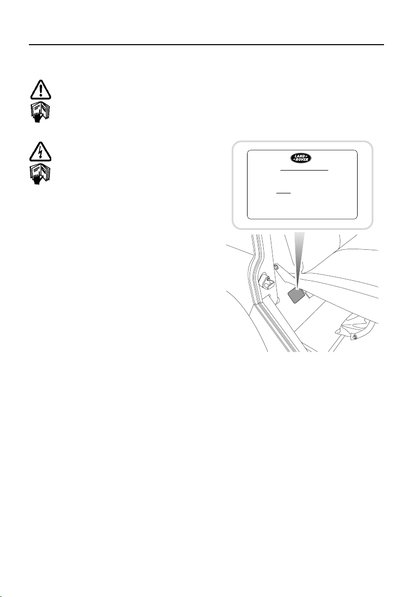
WARNING LABELS
Labels are attached to your vehicle at several
positions. These are applied to draw your
attention to important subjects such as tyre
pressures, tow bar usage, airbags, roll over
risk, engine compartment hazards, etc,
IMPORTANT
BEFORE JACKING VEHICLE
1. ENGAGE DIFF. LOCK. (i.e. WARNING
LIGHT MUST BE ILLUMINATED
PRIOR TO SWITCHING OFF IGNITION.)
2. APPLY HANDBRAKE.
3. CHOCK WHEELS
H4730
It is important that you are familiar with these
subjects to ensure that your vehicle and its
features are used safely. Using the index at the
back of this handbook, refer to the relevant
topic for more information.
18

Keys and Remote Controls
Controls and Instruments
Keys and Remote C ontrols
KEYS AND REMOTE CONTROLS
You have been supplied with two remote
controls and two sets of keys, comprising:
• A black key for operating the starter switch
and door locks.
• A smaller metal key to operate the fuel filler
cap lock.
The starter key number is stamped on a tag
attached to the key ring. Check that the key
number has been entered in the space provided
on your Security card.
If the remote control is lost, contact a Land
Rover Dealer/Authorised Repairer, who can
supply a replacement unit.
WARNING
Keep the Security card and spare remote
control and keys in a safe place - NOT IN THE
VEHICLE.
19
Fascia Controls
H5004
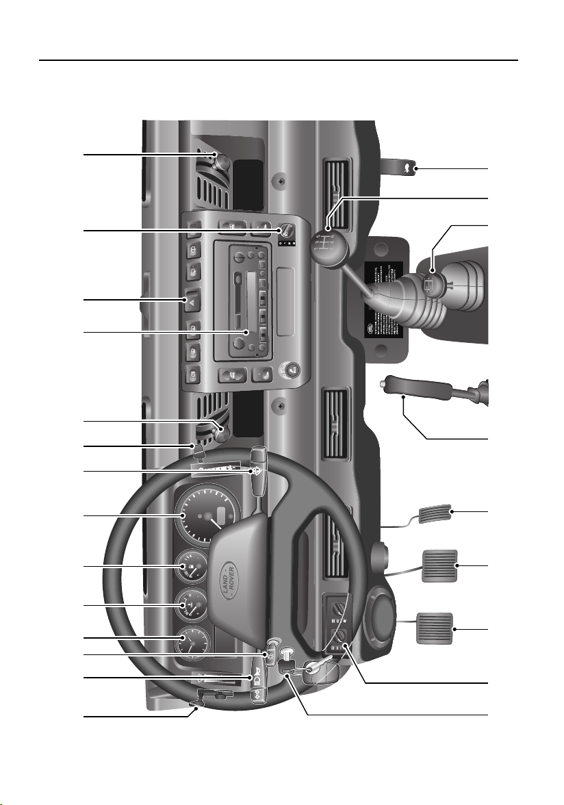
FASCIA CONTROLS
11 12 13 14
10
Fascia Controls
160
180
140
200
120
100
km/h
80
0
60
20
40
39
6
12
2 3 4 5 6 7 8 9
1
22 21 20 19 18 17 16 15
23
20

Fascia Controls
FASCIA CONTROLS KEY
1. Air temperature and distribution controls
2. Direction indicators and horn control
3. Master lamp switch
4. Clock
5. Temperature gauge
6. Fuel gauge
7. Speedometer
8. Windscreen wiper/washer control
9. Air blower control
10. Fresh air vent control
11. Audio system
12. Fascia switches
13. Headlamp levelling switch
14. Fresh air vent control
15. Bonnet release lever
16. Main gear lever
17. Transfer gear lever
18. Handbrake
19. Accelerator pedal
20. Brake pedal
21. Clutch pedal
22. Air conditioning controls
23. Starter switch
*
NOTE: The precise specification and location of the controls may vary according to territorial
requirements and from model to model within the vehicle range.
21
Locks and Alarms
Locks and Alarms
ALARM SYSTEM*
Your vehicle is fitted with a sophisticated
electronic anti-theft alarm and engine
immobilisation system. In order to ensure
maximum security and operating convenience,
you are strongly advised to gain a full
understanding of the alarm system, by
thoroughly reading this section of the
handbook.
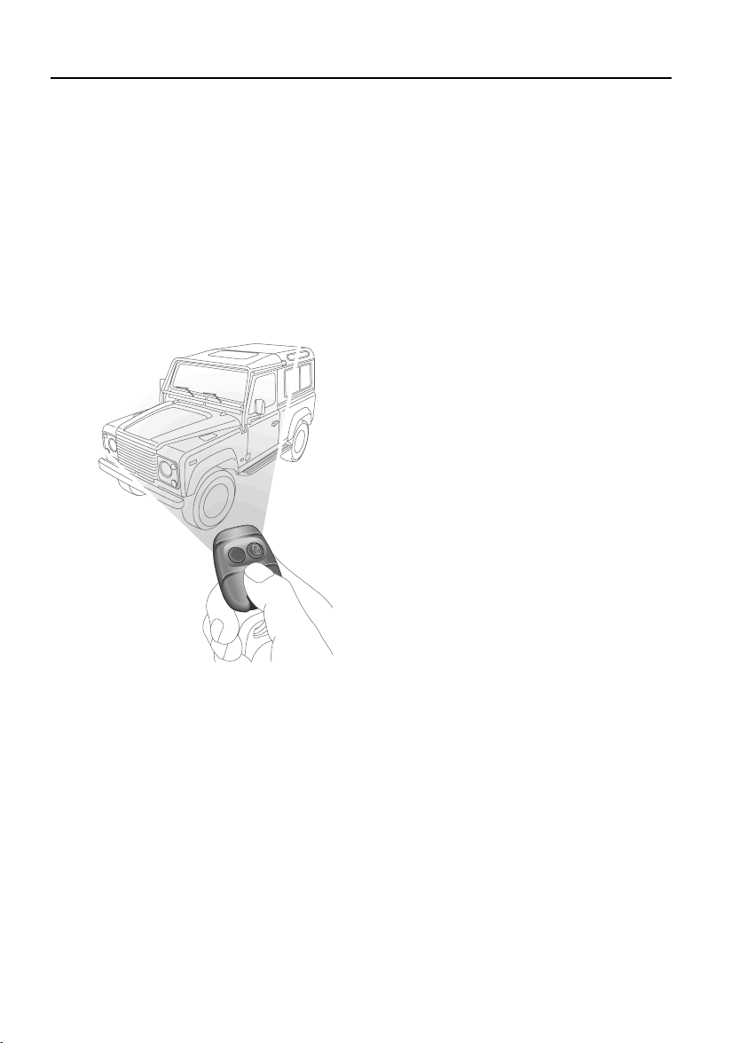
Using the remote control
H3619
While it is not necessary to point the remote
control at the vehicle, the remote control must
be within range of the vehicle when a button is
pressed. Note that the operating range may
vary depending upon remote control battery
condition and may sometimes be limited by
physical and geographical factors beyond your
control. From a security point of view, it may
not be wise to unlock unless you are within a
few feet of the vehicle.
Vehicles with central door locking
Locking with the remote control:
Press the lock (padlock symbol) button once:
• all doors are locked (including the tail door)
• engine immobilised
• perimetric alarm activated (protects the
doors and bonnet)
• interior space protection activated
The direction indicator lamps flash three times
to confirm that the vehicle is secure and the
anti-theft alarm indicator (in the instrument
panel) starts to flash.
Locking with the key:
Insert the key and turn the driver’s door lock
towards the rear of the vehicle:
• all doors locked (including the tail door)
• engine immobilised
• NO PERIMETRIC ALARM OR INTERIOR
SPACE PROTECTION
The anti-theft alarm indicator (in the instrument
panel) starts to flash after 30 seconds to show
that the engine is immobilised.
Unlocking with the remote control:
Press the unlock (PLAIN) button once to
disarm the alarm and unlock the doors.
The direction indicator lamps flash once and
the interior lamps illuminate.
Unlocking with the key:
While all the doors can be unlocked using the
key in the driver’s door lock, this method is NOT
RECOMMENDED - depending on the
specification of the vehicle the alarm may not
be disarmed.
*
22
Locks and Alarms
Vehicles without central door locking
Locking and unlocking:
Each door lock must be operated individually,
using the key. The remote control will NOT
operate the door locks. Turn the key towards
the rear of the vehicle to lock and towards the
front to unlock.
Arming & disarming the alarm:
Press the lock button on the remote control to
arm the alarm.
• Perimetric protection protects the doors
and bonnet.
• Interior space protection is activated.
• Engine is immobilised.
Provided the doors and bonnet are securely
closed, the direction indicators will flash three
times and the anti-theft alarm indicator in the
instrument panel will start to flash.
To disarm the alarm, press the unlock (PLAIN)
button on the remote control; the direction
indicators will flash once and the interior lamps
illuminate.
Door sill locking buttons
From inside the vehicle, each door can be
individually locked by depressing the
appropriate sill locking button.
H3664
WARNING
DO NOT depress the sill buttons as a means of
locking the doors from outside the vehicle
(this practice - known as ‘slam locking’ - is
NOT recommended, because keys can be
locked inside accidentally).
On vehicles with central door locking, operation
of the driver’s door sill locking button locks all
the other doors too. However, engine
immobilisation and interior space protection
are suspended unless the remote control lock
button is pressed as well.
NOTE: Slam locking, as described above, is
prohibited on vehicles with central door
locking.
23

Locks and Alarms
2
Anti-theft alarm indicator
100
120
80
60
40
20
0
H3662
140
160
180
200
The indicator lamp in the speedometer
(arrowed in illustration) provides information
about the status of the alarm system, as
follows:
When the alarm is armed:
The lamp flashes rapidly while the alarm is
arming itself. After 10 seconds, the lamp
adjusts to a slower frequency and continues to
flash as an anti-theft deterrent until the alarm is
disarmed.
If the engine is immobilised (even though the
alarm has been disarmed):
The lamp flashes slowly until the engine is
remobilised.
Mislock
If a door is not fully closed when the remote
control lock button is pressed, the hazard
warning lamps will fail to flash, indicating a
mislock. In this case, the alarm system will not
be fully armed and on vehicles with central door
locking, none of the doors will lock.
As soon as the open aperture is closed, the
hazard warning lamps will flash and the
anti-theft alarm indicator lamp will resume
flashing to confirm that the system has
returned to a fully armed state.
NOTE: If a mislock occurs as a result of an open
door, interior space protection will not be
activated.
NOTE: If a mislock occurs as a result of an open
bonnet, the door apertures will still be protected
by the alarm system and interior space
protection will be active.
If the alarm sounds
If the alarm is triggered, the alarm sounder or
vehicle horn will sound for 30 seconds before
switching off and resetting itself to the same
protection status that existed prior to the alarm
being triggered. The alarm can be triggered up
to three times before needing to be reset.
If the alarm has been triggered:
The lamp will flash rapidly when the alarm is
disarmed until the starter switch is turned to
position II.
If the remote control battery power is low:
The lamp will flash rapidly during the initial
10 seconds after the remote control has been
used, while the alarm system is arming.
If the driver’s door is open:
The lamp illuminates for 10 seconds, before
adjusting to slow frequency flashing.
To silence the alarm, press either button on the
remote control.
NOTE: While the alarm is sounding, the hazard
warning lamps will flash to provide a visual
alarm.
24

Locks and Alarms
INTERIOR SPACE PROTECTION*
H3597
Interior space protection is designed to protect
the interior of the vehicle from intrusion (entry
by a thief through a smashed window, for
example). Twin sensors monitor the interior
space and activate the alarm if air movement is
detected in the passenger compartment.
Using the remote control:
Interior space protection is activated
automatically whenever the remote control is
used to set the alarm and can ONLY be
deactivated with the remote control.
Key operation:
On vehicles fitted with central door locking,
using the key to arm the alarm will NOT activate
(or deactivate) interior space protection.
NOTE: Interior space protection cannot be
activated if a door is open, or if the starter
switch is turned on.
Interior protection will not operate for the first
15 seconds after the alarm is set.
Vehicles without central door locking
To disable interior space protection when
setting the alarm, use the following procedure:
1. Open the driver’s door.
2. With the driver’s door open, use the
remote control to arm the alarm in the
normal way.
3. Close the driver’s door (the hazard
warning lamps flash three times and the
anti-theft indicator lamp commences
flashing rapidly).
The alarm system is now armed with interior
protection disabled.
NOTE: Never activate interior space protection
if windows or sunroof are to be left open, or if
passengers or animals are to be left inside the
vehicle - any movement will activate the alarm.
25
Locks and Alarms
ENGINE IMMOBILISATION
Engine immobilisation is an important aspect of
the security system, and includes a feature
known as ‘passive immobilisation’. This is
designed to safeguard the vehicle from theft,
should the driver forget to lock the doors or arm
the alarm. Engine immobilisation is automatic
whenever any of the following conditions
occurs:
• The vehicle is locked using remote control
or key.
• Thirty seconds after the starter switch has
been turned off AND the driver's door
opened.
• Five minutes after the starter switch is
turned off, or the alarm system is disarmed.
The engine is re-mobilised when the vehicle is
unlocked using the remote control. However, if
no further action - such as ignition being turned
on - takes place within the next five minutes,
passive immobilisation will occur.
The engine immobilisation system relies on the
remote control to re-mobilise the engine. Look
after the remote control at all times, protecting
them from loss, damage and battery discharge.
If the engine has immobilised passively,
re-mobilisation will occur when the starter
switch is turned to position ‘II’, provided the
remote control is on the same ring as the key
and in close proximity to the switch.
• ALWAYS keep the remote control on the
same ring as the key.
• NEVER attach both remote controls to the
SAME key ring.
Any attempt to start the engine while it is
immobilised, will cause the engine
immobilisation warning indicator (in the
speedometer) to flash.
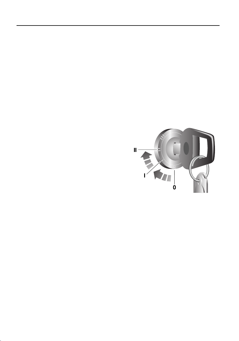
Emergency key access
If the remote control is damaged, or fails to
operate, the engine can be re-mobilised by
using the starter key to enter a unique four
number emergency key access code. The code
is recorded on the Security card and is entered
as follows:
If your remote control is lost or inoperative, it is
impossible to disarm the alarm. As soon as the
door is opened, the alarm will sound
(continuously for up to three 30-second
periods), and continue while the code is being
entered.
H6631
1. Remove the remote control from the key
ring and keep the remote control well
away from the starter switch when
entering the code.
2. From inside the vehicle, with the driver’s
door closed, immediately insert the key
into the starter switch and turn to position
‘II’. Hold this position until the alarm
sounds, then switch off and open and
close the driver’s door.
3. Turn the starter switch to position ‘II’ the
required number of times to enter the first
digit of the code (if the first digit is 4, turn
the key to position ‘II’ and then back to ‘0’
four times).
4. Open and close the driver’s door (this will
enter the first digit of the code).
26

Locks and Alarms
5. Turn the starter switch to position ‘II’ and
back to ‘0’ the required number of times to
enter the SECOND digit of the code.
6. Open and close the driver’s door again.
7. Turn the starter switch to position ‘II’ and
back to ‘0’ the required number of times to
enter the THIRD digit of the code.
8. Open and close the driver’s door again.
9. Turn the starter switch to position ‘II’ and
back to ‘0’ the required number of times to
enter the FOURTH digit of the code.
10. Finally, open and close the driver’s door
one more time.
If the code has been entered correctly, the
anti-theft indicator will extinguish, the alarm
will stop sounding and the engine can be
started.
If an incorrect code has been entered:
If the code is entered incorrectly, the alarm
sounder will sound twice, the anti-theft
indicator lamp will continue to illuminate, and
the engine will fail to start. Before entering the
code again, turn the starter switch to position
‘II’ and hold in this position for 5 seconds.
After three failed entry attempts, the security
system invokes a delay period of 30 minutes
during which the system will not accept any
further attempts to enter a code.
Memorise the emergency key access code or
keep the Security card on your person in case
of emergencies. NEVER leave the card in the
vehicle.
REMOTE CONTROL BATTERY
The battery should last for approximately
three years dependent upon use. When the
battery needs replacing it will be apparent from
the following symptoms:
• The remote control will only work every
other operation while disarming.
• The hazard warning lamps will not flash
when the alarm is disarmed.
• DO NOT remove a battery until you are ready
to install the replacement.
• The engine will immobilise five minutes
after the key is removed from the starter
switch (or 30 seconds after the starter has
been switched off and the driver’s door
opened). If remote control battery
replacement is NOT completed within this
period, the emergency key access code will
have to be entered before the remote control
can be synchronised.
Always fit a Land Rover STC 4080 or a
Panasonic CR2032 replacement battery
(available from a Land Rover Dealer/Authorised
Repairer).
WARNING
The remote control contains delicate
electronic circuits and must be protected from
impact and water damage, high temperatures
and humidity, direct sunlight and the effects
of solvents, waxes and abrasive cleaners.
27
Locks and Alarms
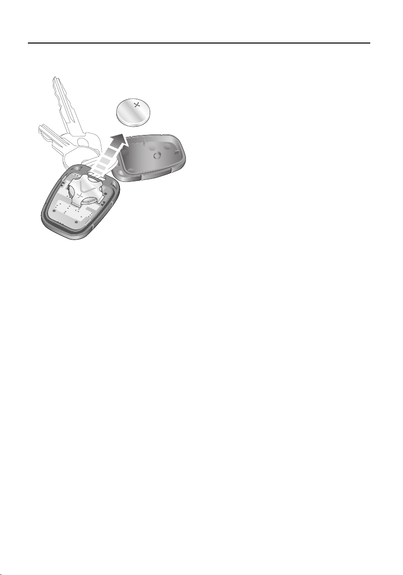
Battery replacement
H3663
1. Unlock the vehicle and disarm the alarm
system.
2. Turn the starter switch to position ‘II’, then
turn to position ‘0’ and remove the key.
3. Carefully prise the remote control apart;
start from the key ring end using a coin or
small screwdriver. Avoid damaging the
seal between the two halves of the case
and DO NOT allow dirt or moisture to get
inside the remote control.
4. Slide the battery out of its clip, taking care
to avoid touching the circuit board or the
contact surfaces of the clip.
5. Press and hold one of the buttons for at
least five seconds (this will drain any
residual power from the remote control).
6. Fit the new battery, ensuring that correct
polarity is maintained (‘+’ side facing up).
Finger marks will adversely affect battery
life; if possible, avoid touching the flat
surfaces of the battery and wipe them
clean before fitting.
7. Press the two halves of the remote control
firmly together and ensure that both
halves are fully joined, to prevent dirt or
moisture from entering the remote
control.
8. Operate the PADLOCK symbol button at
least four times within range of the vehicle
to synchronise the remote control.
9. Press the unlock button once to unlock the
vehicle.
The remote control is now ready for use.
28
Locks and Alarms
ALARM OR REMOTE CONTROL
DIFFICULTIES
If the alarm goes off unexpectedly:
Ensure all the windows and sunroof are closed,
or if they need to be left open, disable interior
space protection.
If the alarm goes off when a door is opened:
Disarm the alarm with the remote control
before unlocking. If the remote control has
failed, enter the emergency key access code
(refer to ‘Emergency key access’, page 26).
If the starter will not operate:
Ensure the remote control is on the same key
ring as the starter key. If it still will not operate,
consult a Land Rover Dealer/Authorised
Repairer.
If the hazard warning lamps fail to flash when
the alarm is armed:
A door or bonnet is partially opened - close the
open aperture and try again.
Battery disconnection
Your vehicle is equipped with a battery
backed-up sounder
anti-theft siren if the vehicle battery is
disconnected.
*, which operates as an
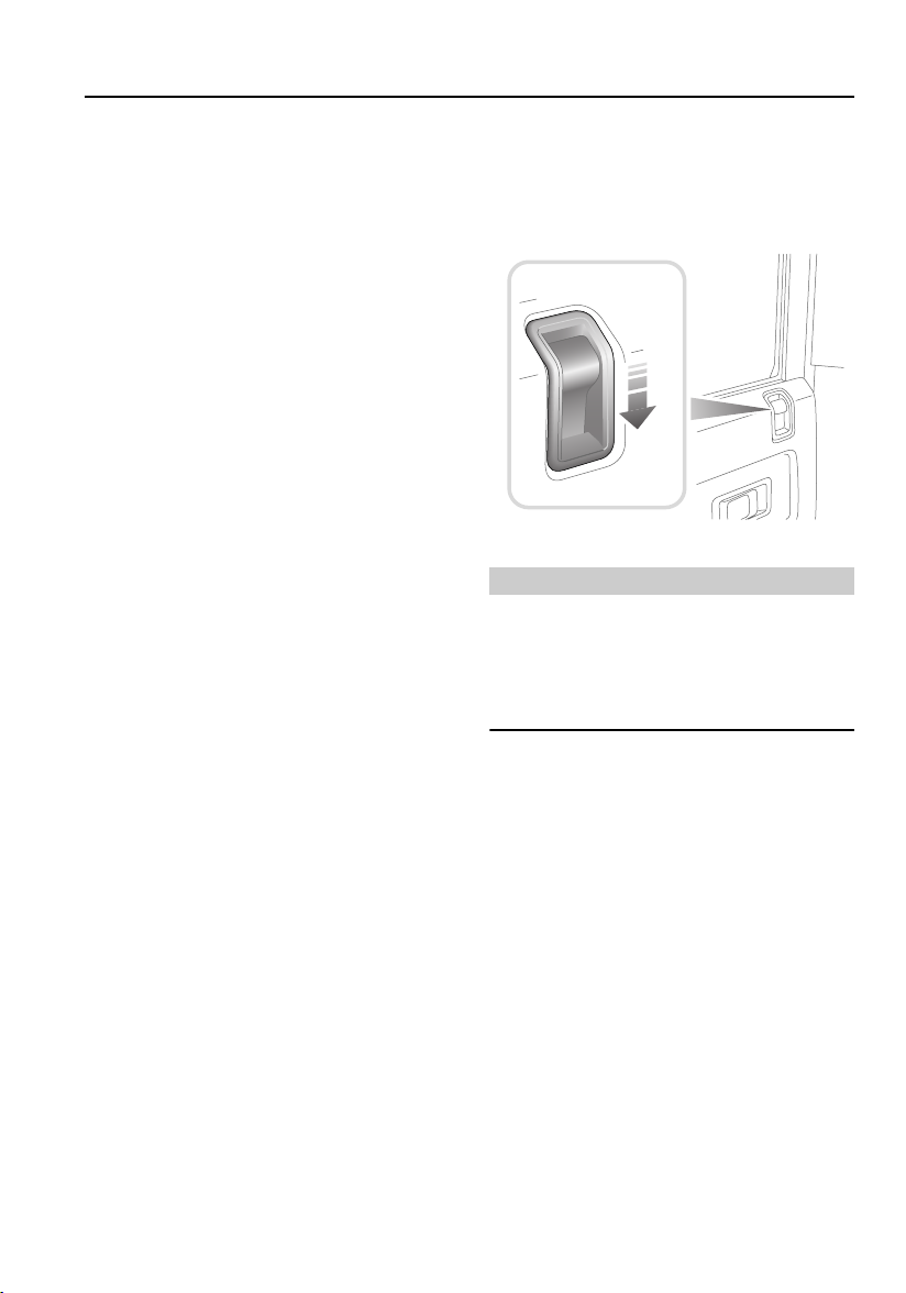
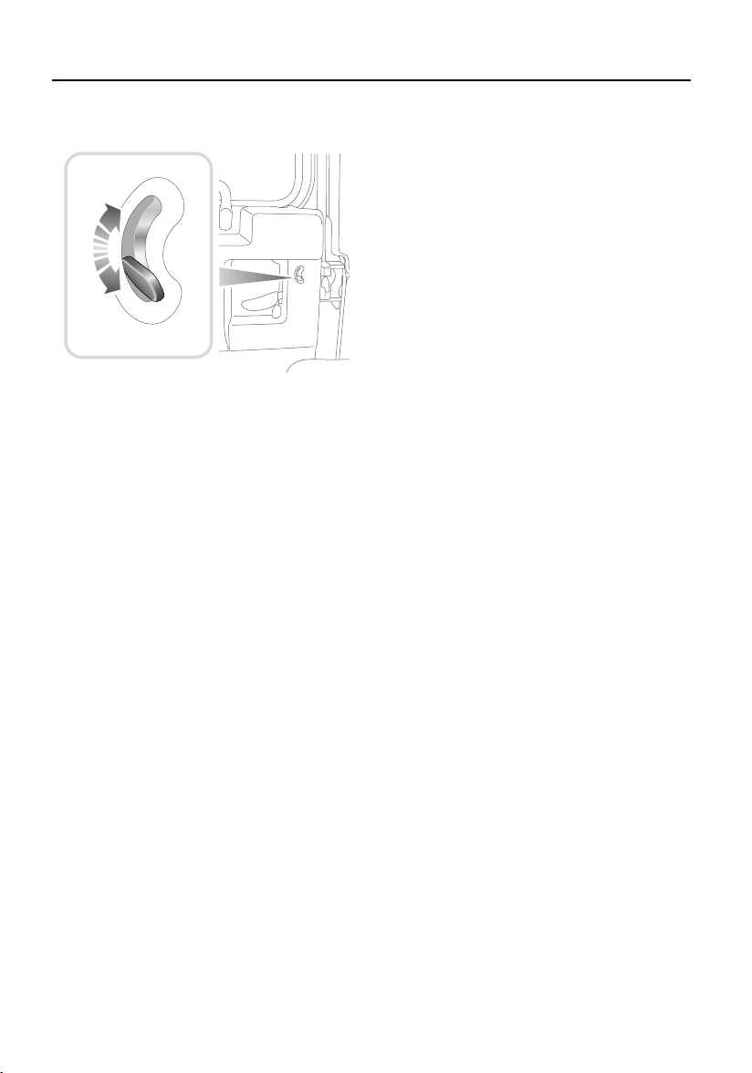
CHILD-PROOF LOCKS*
H3661
Move the locking levers on the rear doors down
to engage the child locks.
With the child-proof locks engaged, the rear
doors cannot be opened from inside the
vehicle, thereby avoiding the risk of a door
being opened accidentally while the vehicle is
moving.
WARNING
NEVER leave children unsupervised in the
vehicle.
Before disconnecting the vehicle battery, it is
ESSENTIAL to refer to, in order to prevent the
alarm from sounding.
If the vehicle battery is disconnected for any
reason, the status of the security system prior
to disconnection will be memorised and
automatically reset when the battery is
reconnected.
29
Locks and Alarms
TAIL DOORS*
H3618
From outside, use the key to lock and unlock
the taildoor. From inside and with the door
closed, push the locking button up to lock and
down to unlock (see illustration).
30
 Loading...