


Powered Lawnmowers —
Walk Behind
Model Nos. 51, 61 - 20” (508mm)
Model No. 80 - 22” (560mm)
TM

LABELS
• Symbols are used on the machine to communicate important information.
• A list of symbols and their meanings are shown below.
• Please familiarise yourself with them before operating the machine.
Rover Mowers Ltd
ABN 11 000 257 303
TM
• Caution
• Keep hands and feet away
• Rotating blades in cutterhead
• Caution rotating blades while doing maintenance
• Wear foot protection
• Refer to the Owners Manual for
maintenance details
• Fast speed
• Slow speed
• Push handle to handle bar to drive mower forward
• Wear eye protection
• Wear hearing protection
• Engine choke
• On or start - switch, lever or position
• Off - switch, lever or position
• Disengage - switch, lever or position
• Wear hand protection
Powered Walk Behind Mower Part No. 04016067 Rev E © Copyright 6/2005
ii
• Engage - switch, lever or position

Powered Walk Behind Mower Part No. 04016067 Rev E © Copyright 6/2005
Rover Mowers Ltd
ABN 11 000 257 303
TM
PREFACE
Congratulations on your purchase of a qualit y Australian made and designed product from an Australian owned company.
This manual covers the operation and maintenance of the Rover Walk Behind Powered Lawn Mowers, as listed on the front cover of this manual.
Please read and understand this and any associated manual before using this machine. If any point is unclear, please contact any
authorised Rover service dealer.
WARNING
Symbols
The following symbols have been used in this manual to highlight important information:
This symbol warns against injury to the operator or bystanders.
WARNING
This symbol warns against mower damage or possible loss of warranty.
CAUTION
This symbol highlights good ideas or tips.
TABLE OF CONTENTS
LABELS................................................................................. ii
PREFACE ..............................................................................iii
SAFETY INSTRUCTIONS ....................................................1
COMPONENTS ...................................................................1
SPECIFICATIONS ................................................................. 2
SETTING UP ........................................................................2
Assembly of the Grass Catcher
Folding the Handle
Adjusting the Handle Height
Engine Lubrication and Fuel
Powerstart Option
Self Propelled Option
OPERATION ........................................................................3
Grass Catcher
- Installing the Grass Catcher
- Removing the Grass Catcher
Mulch Plug
Grass Deflector
Adjusting the Cut Height
Engine
- Starting the Engine
- Stopping the Engine
Grass Cutting and Catching
Self Propelled Option
MAINTENANCE..................................................................5
General Cleaning
- Cleaning the Underside of the Mower
- Cleaning the Upperside of the Mower
Changing the Cutting Blades
Remote Air Cleaner Option
Self Propelled Option
- Adjusting the Drive Cable
- Removing the Drive Frame Cover
- Replacing the Drive Frame Cover
- Drive Chain Lubrication
- Drive Chain Adjustment
- Drive Belt Adjustment
- Drive Belt Replacement
- Adjusting the Drive Clutches
- Lubricating the Drive Pawls
Powerstart Option
TROUBLE SHOOTING ....................................................... 11
General
Powerstart Option
Self Propelled Option
WARRANTY.......................................................................13
General
Exclusions
iii

SAFETY INSTRUCTIONS
• Never mow while barefoot or wearing open sandals, or thongs. Wear long trousers and heavy shoes.
• Know your controls. Read the owner’s manual carefully. Learn how to stop the engine quickly in any emergency.
• Make sure the lawn is clear of sticks, stones, bones, wire and debris. They could be thrown by the blade.
• Stop the engine and disconnect spark plug wire (on internal combustion engines) or disconnect the mower from the
mains (on electric mowers) before clearing blockages, checking or working on the mower.
• Before using, always visually inspect to see that blades, blade bolts and cutter assembly are not worn or damaged.
Replace worn or damaged blades and bolts in sets to preserve balance.
DAMAGED BLADES AND WORN BOLTS ARE MAJOR HAZARDS
• Check all nuts, bolts and screws of ten; always be sure the mower is in safe operating condition. Use only
replacement parts made and guaranteed by the original manufacturer of your mower.
• Refuel outdoors only. Do not smoke while fuelling engine. Add fuel before starting the engine. Never remove
the cap off the fuel tank or add petrol while the engine is running or the engine is hot. If petrol is spilled, do not
attempt to start the engine but move machine away from the area of the spill and avoid creating any source of
ignition until petrol vapours have dissipated.
• Do not mow whist people, especially children, or pets are in the mowing area.
• Replace worn or faulty silencers.
• Mow only in good daylight.
• Never use the mower unless the grass catcher, or guards provided by the manufacturer, are in position.
• Start the engine carefully with feet well away from the blades.
• Do not operate the engine in a confined space where exhaust fumes (carbon monoxide) can collect.
WARNING
• Stop the engine whenever you leave the mower, even for a moment.
• Do not allow children or people unfamiliar with these instructions to use the mower.
• Store the mower in a well ventilated room away from naked flames such as may be found in hot water heaters.
• Never use an electrically powered mower in the rain or when the grass is wet.
• Never leave wind up starters in a wound condition.
• Do not over-speed the engine or alter governor settings. Excessive speed is dangerous and shortens mower life.
• It is advisable to wear suitable eye protection when operating a mower.
• Turn the fuel off at the conclusion of mowing and reduce the throttle setting during the engine run-out.
• Store fuel in a cool place in a container specifically designed for the purpose. In general, plastic containers are
unsuitable.
• Stop the engine, disconnect the spark plug wire or mains power cord, as applicable, and inspect the mower if-
(a) the mower begins to vibrate abnormally; or
(b) after striking a foreign object.
• Never cut grass while walking backwards.
• Stop the engine before pushing the mower across gravel drives, walks or roads.
• Walk, never run.
• Mow across the face of slopes, never up and down. Exercise extreme caution when changing direction on slopes.
Do not mow excessively steep slope.
• Never pick up or carry a mower when it is operating.
Rover Mowers Ltd
ABN 11 000 257 303
TM
COMPONENTS
• Ensure that all the following component parts are included in the package (refer f igure 1):
- Mower (1 off)
- Kit including: Owners Manual (1 of)
Engine Manual (1 of)
Spark Plug Spanner (1 of)
Screw - 3/16” x 1/2” UNC (2 of)
Nyloc Nut - 3/16” UNC (2 of)
Washer - 3/16” x 1/2” flat (2 of)
- Grass catcher bottom (1 of)
- Grass catcher top (1 of)
- Grass catcher handle (1 of - may be loose or fitted to Grass catcher top)
NB. Other accessories may be included in the carton which vary with each model. These items will be covered by a
separate owners manual e.g. Mulch Mowing Kit, Grass Deflector Kit, etc.
• Notify the place of purchase of missing items as soon as possible.
Powered Walk Behind Mower Part No. 04016067 Rev E © Copyright 6/2005
1
1

Powered Walk Behind Mower Part No. 04016067 Rev E © Copyright 6/2005
2
Rover Mowers Ltd
ABN 11 000 257 303
TM
SPECIFICATIONS
• This manual covers several mowers with the following specif ications:
- Models 51, 61 - 20” (508mm Cut Width)
- 12 Cut Height Settings
- Model 80 - 22” (560mm Cut Width)
- 15 Cut Height Settings
NB. - Models come with one of a range of engines (refer to the engine manual included in the kit)
- Options are available (and may be included) on the above models e.g.
- Mulch Mowing
- Deflector Mowing
- Remote Air Cleaner
- Powerstart Function
- Self Propelled Function
- etc.
- Details may be included in this manual or on a separate manual included in the Mower Kit.
SETTING UP
• Before using the Mower the following set-ups are required:
ASSEMBLY OF THE GRASS CATCHER
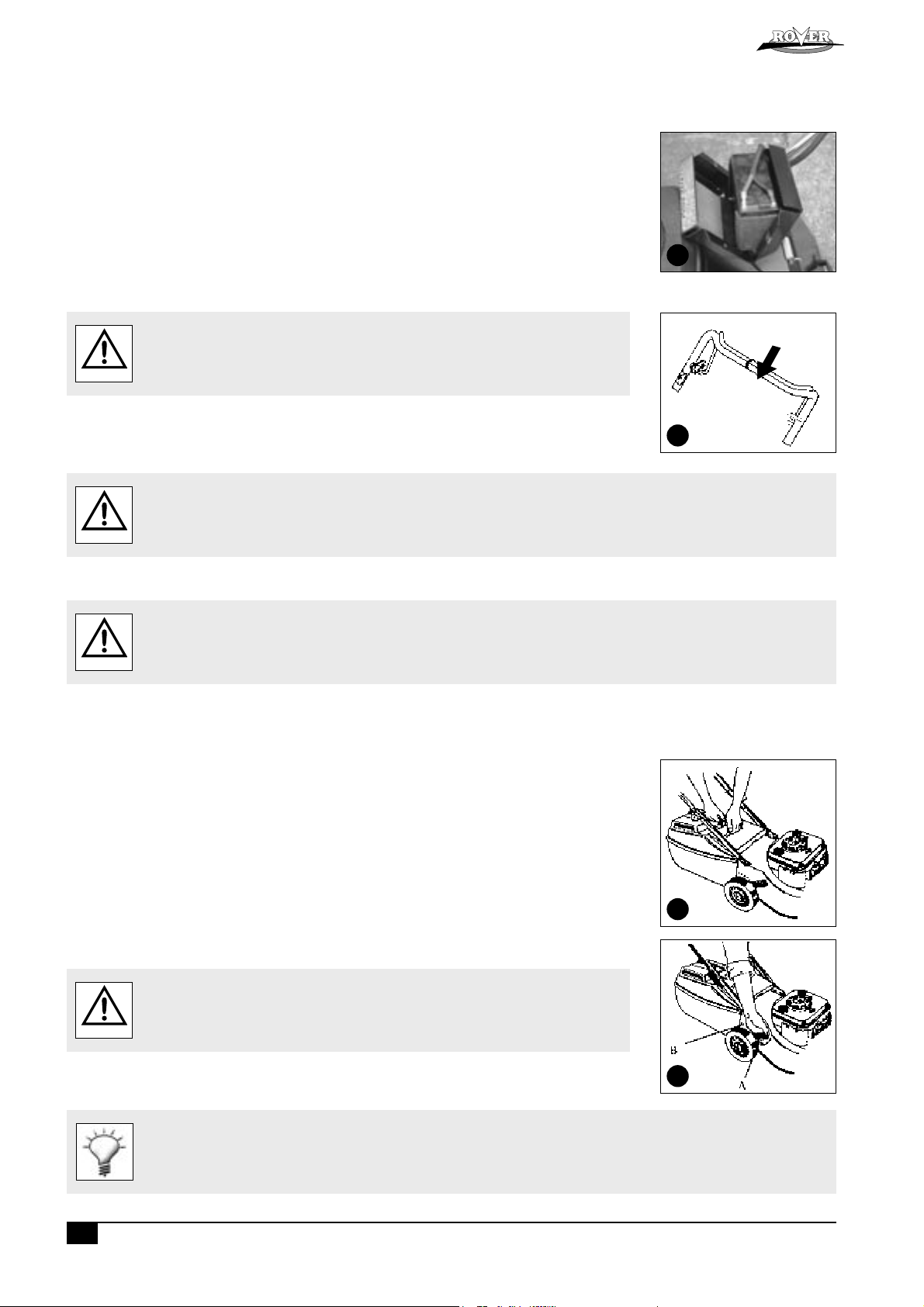
• Locate the catcher handle and align its front lugs with the slots in the top of the catcher and press firmly into position
(refer figure 2).
• Position the catcher top over the catcher bottom, aligning the barbs on the top with the slots in the bottom (refer
figure 2).
• Press firmly down on the catcher top to lock the barbs into slots (refer figure 2).
• Secure the top and bottom halves of the grass catcher together at the front using the two 3/16” screws, washers and
nyloc nuts supplied. Insert the screws from the outside with the washers and nyloc nuts on the inside of the catcher.
FOLDING THE HANDLE
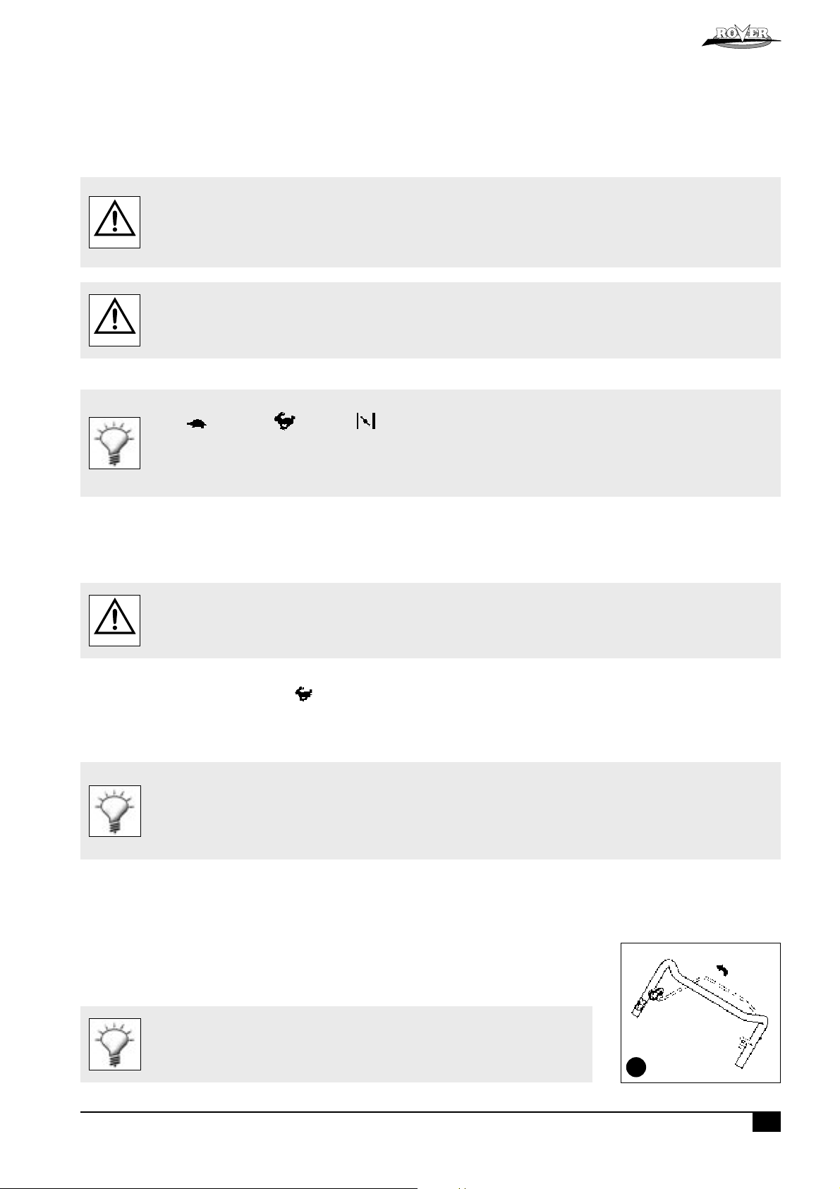
• Locking knobs: by turning these knobs the handle bars can be either locked in the operating position or folded for storage.
• Locking lever: lift the lever to release the handle bars for folding or push the lever closed to lock handle bars in the
operating position. Adjust the tension by turning the lock nut with a 1/2" AF spanner (refer figure 3 A).
ADJUSTING THE HANDLE HEIGHT
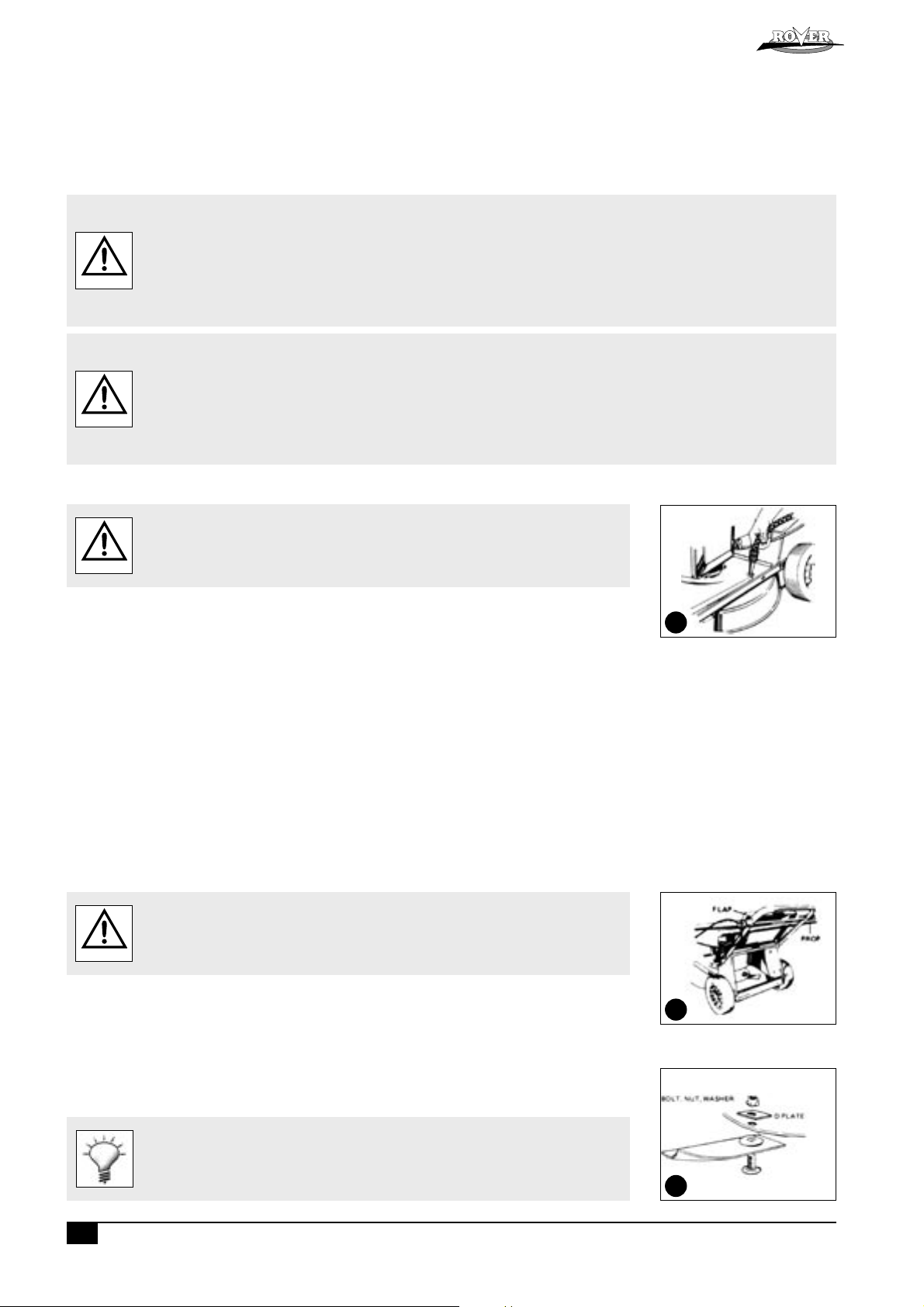
• Loosen the two nuts (B) at the base of the handle bars on both sides of the mower using a 1/2" AF spanner (refer
figure 3).
• Move the handle bars to the required position and tighten the handle bars nuts.
ENGINE LUBRICATION AND FUEL
The engine safety precautions, oil and fuel recommendations, operation instructions, adjustments and maintenance is covered in the
engine manufacturer’s manual which is included in the mower kit. Please refer to and adhere to these recommendations.
If you do not have the engine manufacturer’s manual please refer to the nearest engine
manufacturer’s representative for a replacement copy.
CAUTION
The engine is packed without oil or fuel. Please add these as per the engine manufacturer’s recommendations before attempting
to start the engine.
Do not allow any dirt or contaminants to enter the fuel tank or oil filler tube.
2
A
B
3
POWERSTART OPTION
The battery must be removed from the mower while recharging.
Only use the battery charger indoors where it cannot be af fected by weather.
The battery contains a strong acid electrolyte which may cause personal and material damage.
- Do not disassemble, drop or damage the bat tery.
WARNING
- Do not incinerate or expose the bat tery to high heat or a f lame or it may explode.
- Dispose of bat teries thoughtfully. Refer to your local regulations for battery disposal.
- Replace any leaking battery immediately.
- Clean the bat tery only with a dr y cloth - never use petrol, thinners or other petrochemical.
- Neutralize any electrolyte spills with an alkaline solution.
SETTING UP (Continued)
POWERSTART OPTION
• Remove the two screws from the battery support box, rotate the battery and lid forward and expose the battery
terminals.
• Slide the red and black wire from the battery terminals and remove the battery.
• Place the battery in a dry, cool area and connect the battery charger cables to the battery terminals (red [+] to red
[+] and black [-] to black [-]).
• Connect the battery charger to a 240 volt power outlet and switch it on.
• Allow to charge for 10-16 hours, switch the 240 volt power outlet off and remove the battery charger cables from
the battery.
• Refit the rubber battery blocks to each end of the battery and refit into the battery support box.
• Slide the wiring loom connections onto the battery terminals red [+] to red [+] and black [-] to black [-].
• Locate the battery support box lid, refit and tighten the two screws (refer figure 4).
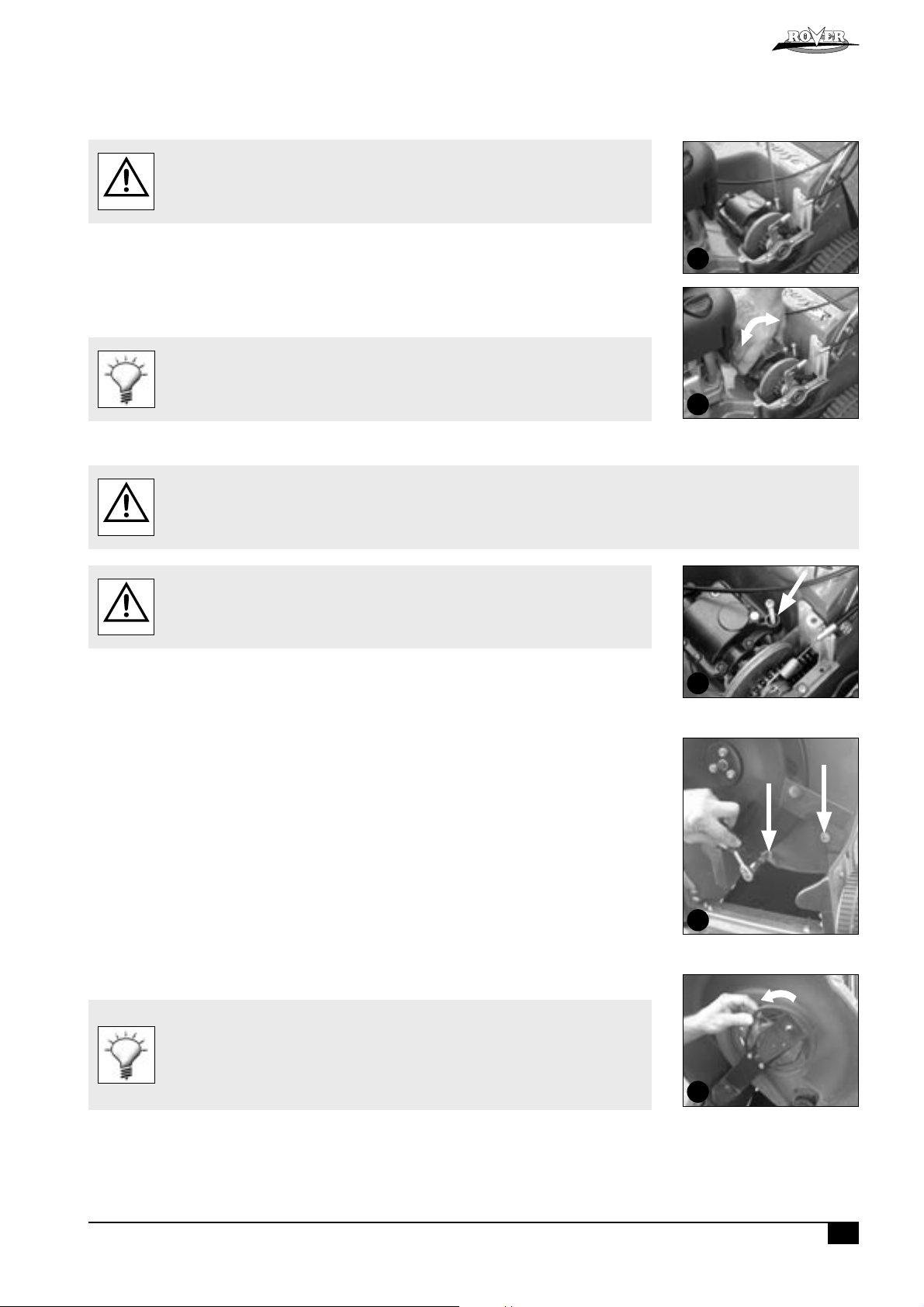
SELF PROPELLED OPTION
Remove and discard the packaging tie clamping the self propelled drive control bale to the
handle bar before attempting to start the mower (refer figure 5).
WARNING
OPERATION
TM
Rover Mowers Ltd
ABN 11 000 257 303
4
5
• Refer to and follow the “Safety Instructions” in this and any other associated manuals supplied with this product before attempting
to operate this machine.
• Refer to and understand the safety symbols fitted to the machine and shown in the “Labels” section of this manual.
WARNING
• Ensure that all the items in the “Setting Up” section have been completed.
GRASS CATCHER
• Never install or remove the Grass catcher with the engine running.
WARNING
Installing the Grass catcher
•Raise the rear flap of the mower.
• Grasp the grass catcher by the top handle and position the grass catcher against the rear of the mower (refer figure 6).
• Lower the rear f lap so that the back edge of the flap hooks over the matching lip on the grass catcher.
Removing the Grass catcher
•Grasp the grass catcher top handle and lift up.
• Raise the rear flap of the mower to release grass catcher.
• Lift the grass catcher clear of the mower and lower the rear flap.
MULCH PLUG
• Refer to the separate Mulch ‘n’ Catch Owners Manual.
GRASS DEFLECTOR
• Refer to the separate Grass Deflector Owners Manual.
6
ADJUSTING THE CUT HEIGHT
• When setting the cut height stand to the rear of the machine with your feet well clear of
WARNING
the cutting blades.
• Grasp the height of cut lever (A) and apply an outward pressure to release the lever from the rack (B) (refer figure 7).
• Move the lever (while holding out) to the required height of cut position and engage the lever in the rack.
7
• Pushing the lever forward and down raises the cut height and vice versa.
It is advisable to start the mower in the high cut position and gradually drop the height notch by notch until the desired height is
achieved. Starting too low will leave a low spot in the lawn.
Powered Walk Behind Mower Part No. 04016067 Rev E © Copyright 6/2005
3
Powered Walk Behind Mower Part No. 04016067 Rev E © Copyright 6/2005
4
Rover Mowers Ltd
ABN 11 000 257 303
TM
OPERATION (Continued)
ENGINE
NOTE: The mowers covered in this manual have various engine types from various manufacturers. Included in the Mower
Kit is an engine manual specific to each mower which provides the details for the engine’s operation. Please refer to the
engine manufacturer’s manual for precise instructions.
Starting the Engine
• The engine safety precautions, oil and fuel recommendations, operation instructions, adjustments and maintenance is covered in the
engine manufacturer’s manual which is included in the mower kit. Please refer to and adhere to these recommendations.
• If you do not have the engine manufacturer’s manual please refer to the nearest engine manufacturer’s representative for a
replacement copy.
CAUTION
WARNING
• The engine is packed without oil or fuel. Please add these as per the engine manufacturer’s recommendations before attempting
to start the engine.
• Refer to the “Warning” notes at the beginning of the “Operation” section.
• Start the mower on a clear level surface.
• Keep your fingers, toes and bystanders clear when starting or operating the engine.
• If fitted with the Powerstar t option, always remove the key from the ignition switch and keep in a safe place to prevent unauthorised
cranking of the engine.
• Refer to the engine manufacturer’s manual for the starting procedure.
• If fitted with the Powerstart option, insert the key into the ignition switch then follow the instructions in the engine manufacturer’s manual.
The Rover throttle control uses symbols to indicate the throttle function at various throttle positions:
O (off), (slow speed), (fast speed), (engine choke)
These positions align with settings required in the engine manufacturer’s manual.
The Rover Powerstart option can be started with an ignition key which is fitted to the handle bar. The switch plate uses symbols to
indicate the key function at various positions and refers to the state of the star ter motor:
O (off), I (on/star t). These positions align with the settings required in the engine manufacturer’s manual.
Stopping the Engine
• Refer to the engine manufacturer’s manual for stopping procedure.
• If fitted with the Powerstart option remove the ignition key and store in a safe place after use.
GRASS CUTTING AND CATCHING
Refer to and abide to the instructions noted in the safety instructions of this and associated manuals.
WARNING
• Fit the Grass catcher to the mower (refer to the “Setting Up” section).
• Start the engine and set the engine speed to fast ( ) on the throttle control.
• Set the desired cut height (refer to “Setting the Cut Height” above).
• Drive the mower forward through the grass until the catcher fills.
• Stop the engine, remove and empty the catcher.
• Repeat the process.
• To maximise the cut ting and catching performance it is impor tant to maintain high engine speed, so adjust the mower ground
speed to suit.
• If the grass length or density is excessive (to maintain high engine speed initially) cut the grass at a higher setting, then at the
desired height.
• Replace blades regularly to maintain a sharp cutting edge.
• Keep the mesh in the grass catcher clean to allow the grass catcher to fill properly.
• Keep the underside of the mower deck clean and free of clipping build-up.
SELF PROPELLED OPTION
Using the Self Propelled Transmission
• Start the engine and set the engine speed to fast.
• Push forward on the clutch engagement lever to engage the self-propelled drive to the rear wheels noting that the drive
speed increases as you move the bale closer to the handle bar (refer figure 8).
• Hold the bale at the required drive speed and slow down or speed up as the conditions dictate.
• To disengage the self-propelled drive release the engagement lever and allow it to return to the disengaged position.
Release the self-propelled drive bale and push the machine when changing direction or mowing
in a confined area for safety.
8
MAINTENANCE
NOTE: The majority of mower problems involve the following problems:
- Dirt or contaminants in the fuel
- Incorrect oil level in the engine
- Blocked, damaged or incorrectly fitted air cleaner
- Incorrectly maintained blades
(Refer to the maintenance section of this and the engine manufacturer’s manual for details.)
• Always ensure equipment is in good working order.
• Do not use any equipment with worn or damaged components.
• Always use genuine Rover replacement parts.
• Never attempt maintenance that is not outlined in this manual. Refer to your nearest authorised Rover Service Dealer.
• Always ensure the engine is stopped and remove the spark plug wire before attempting any maintenance on the mower.
WARNING
CAUTION
• On Powerstar t models remove the key from the ignition before attempting any maintenance on the mower.
• All safety guards, blades, grass catchers and safety labelling must be replaced with genuine Rover parts if worn or damaged.
• Always replace blades and blade fixings in complete sets to maintain balance.
• Remove clipping build-up around the muf fler area to prevent a fire hazard.
• Refer to and abide to engine manufacturer’s manual.
• Do not allow any dirt or contaminants to enter the fuel tank, oil filler tube, air cleaner housing, carburettor or spark plug hole
when maintaining the engine.
• Ensure there is no clipping build-up in the vents adjacent to the recoil starter. The engine may overheat and be damaged if these
vents are not clear.
• Do not use high pressure cleaners to wash the machine and keep water away from the engine and electrical components.
• If tilting the mower, the engine spark plug must remain uppermost to prevent oil seepage into the air cleaner and/or exhaust.
• To prevent fuel leaking from the tank when tilting the mower ensure the fuel level is low or empty.
• Ensure the mower is dry and clean and stored in a well ventilated area.
Rover Mowers Ltd
ABN 11 000 257 303
TM
GENERAL CLEANING
• Refer to the general “Warning” and “Caution” notes at the beginning of this section.
• Never open the discharge flap, or lift the mower to wash the underside of the deck with
WARNING
the engine running.
• To ensure safe operation and long life it is recommended to clean the mower after every use. This will prevent corrosion,
overheating and fire risk while ensuring ultimate performance.
Cleaning the Underside of the Mower
• Place the mower outdoors on a flat surface.
• Remove the grass catcher and close the discharge flap.
• Set the cut height to maximum.
• Start the engine and run at a moderate speed.
• Use a garden hose to direct water through the wash port hole (refer figure 9) for 1-2 minutes.
• Remove the hose and stop the engine.
• Open the rear discharge flap and with the garden hose wash the residual clippings out of the rear section of the mower.
• Inspect the underside and repeat the cycle if still not clean.
Cleaning the Upperside of the Mower
• Use a dry rag or soft brush to remove all loose clippings.
• Use a damp rag with mild detergent to clean away oil or other grime.
• Wash the grass catcher separately from the mower with a hose washing all clippings out of the inside, outside and
from the grass catcher mesh.
• Let the mower dry before storing.
CHANGING THE CUTTING BLADES
Refer to the “Warning” and “Caution” notes at the beginning of this section.
WARNING
9
• With the engine stopped, spark plug wire and grass catcher removed, open the discharge flap and prop in the open
position (refer figure 10).
• Set the mower to high cut and fold the upper handle bar down.
10
• Rotate the cutting assembly carefully to access the blade retaining bolts.
• Using gloves and a suitable spanner, remove the blade assembly.
• Retain the ‘D’ plates (where fitted) and discard the blades and fasteners.
• Fit the new blades and fasten in the correct order (refer figure 11).
• Tighten the blade retaining nuts firmly (16Nm).
• Remove the flap prop, close the discharge flap and refit the spare plug wire.
• Remove all clipping build up from around the blade retaining nuts before f itting the spanner.
• Use a ring or socket spanner to prevent slipping off or damaging the blade retaining nut.
• The blade should be free to rotate if the bolts are fitted correctly.
Powered Walk Behind Mower Part No. 04016067 Rev E © Copyright 6/2005
5
11

Powered Walk Behind Mower Part No. 04016067 Rev E © Copyright 6/2005
6
Rover Mowers Ltd
ABN 11 000 257 303
TM
MAINTENANCE (Continued)
REMOTE AIR CLEANER OPTION
Removing the Remote Mounted Air Cleaner Element (If fitted)
• Keep the air entry vent in the outer housing clear.
• Keep the air cleaner clean and replace if damaged.
• Don’t allow dirt or contaminants to enter the air tube.
CAUTION
Note: only some models are fitted with this option. All other models have the air cleaner located on the engine (refer
to the engine manufacturer’s manual).
• Unscrew the cap (refer figure 12).
• Remove the air cleaner cartridge.
• Tap the air cleaner cartridge gently on a flat surface to dislodge dirt.
• Replace the clean cartridge with the hole down.
• Replace the cap.
SELF PROPELLED OPTION
WARNING
• Replace the air cleaner cartridge if damaged or unser viceable.
Refer to the “Warning” and “Caution” notes at the beginning of the maintenance section.
12
Adjusting the Drive Cable
If cable adjustment is necessary ensure that the drive disengages before starting the mower or it may drive off unattended. This can be
WARNING
CAUTION
checked by pulling the mower backwards (with the drive bale released) - the rear wheels should free wheel.
• Do not overtighten the cable assembly.
• Should the transmission continue to slip after adjustment, have the mower serviced by an
authorised Rover dealer.
• Start the mower in the disengaged position.
• Push the drive bale forward until the gap between the bale and the handle bar is 55mm (refer figure 13).
• The drive should just begin to engage at this point.
• If the drive is not beginning to engage, rotate the thumb wheel on the cable support block (one click at a time) in an anti
clockwise direction until it does (refer figure 14).
• If the drive engages and drives off at a gap greater than 55mm rotate the thumb wheel on the cable support block one
click at a time in the clockwise direction until it does (refer figure 14).
• Test the mower at all speeds ensuring that it self disengages when the drive bale is released and that the transmission does
not slip at full speed with the drive bale fully engaged.
• If you still experience problems, see your nearest authorised Rover dealer.
• Ensure the cable is not damaged or kinked which may affect the drive.
• Apply a drop of lubricant to the pivot points of the drive bale to ensure smooth and safe
operation.
13
14
Anti-clockwise
Removing the Drive Frame Cover
• Unscrew the front and rear phillips head screw in that order (refer figure 15).
• Lift the cover and rotate out of the mower to expose the upper transmission components.
Blow grass and dirt out of the recessed holes to expose the head of the fixings.
15

MAINTENANCE (Continued)
Replacing The Drive Frame Cover
• Make sure the raised ring on the brass section of the drive cable nests into the groove of the lower drive support frame and f it the
lid accurately on top before screwing down the cover.
CAUTION
• Fit the drive cable into its retaining slot in the lower drive support frame and hold it down horizontally with one hand
(refer figure 16).
• Rotate the cover into position over the cable until it seats properly and maintain pressure on the lid above the cable.
• Screw the rear fixing above the cable down firmly.
• Screw the forward fixing down firmly.
• Do not operate the transmission bale with the cover loose or removed as you will damage the lower drive suppor t frame.
Rover Mowers Ltd
ABN 11 000 257 303
TM
Leave the fixings in the lid when removing or replacing.
Drive Chain Lubrication
• Refer to the “Warning” and “Caution” notes at the beginning of the maintenance section.
• Do not apply excessive lubricant to the chain as it may flick off and onto the drive clutches during operation.
WARNING
• Keep lubricant clear of the drive clutches.
• Remove the drive frame cover (refer to the “Removing the Drive Frame Cover” section) to expose the drive chain.
• While rotating the outer clutch plate (clockwise) apply an even spread of suitable (non aerosol) chain lubricant along
the length of the chain (refer figure 17).
• Replace the drive frame cover (refer to the “Replacing the Drive Frame Cover” section).
Put the chain lubricant in a container with a long pointed spout to make application easier.
Apply a little of the lubricant on the cams between the clutch engagement lever and the
outboard output shaft bearing retainer while lubricating the chain.
Drive Chain Adjustment
• Refer to the “Warning” and “Caution” notes at the beginning of the maintenance section.
• Keep the chain correctly tensioned to prevent damage or abnormal wear.
CAUTION
• Do not over tension the chain.
16
17
• Ensure the engine and muffler are cold before attempting to adjust the chain to prevent
WARNING
• Remove the drive frame cover (refer to the “Removing the Drive Frame Cover” section) and expose the drive chain.
• Using a long slender shaft press firmly on the chain as far from the top sprocket as possible (refer figure 18).
burns.
18
• Using a suitable Phillips head screw driver rotate the adjusting screw until the chain deflection (above) is 5mm (refer
figure 19).
• Rotate the outer clutch plate (chain), recheck chain deflection and re-adjust if necessary.
• Replace the drive frame cover (refer to the “Replacing the Drive Frame Cover” section).
• Rotate the chain adjustment screw clockwise (when looking directly at the head of the
screw) to tighten the chain tension and vice versa.
• Use a very long, or right angle single drive phillips head screw driver to better access the
chain adjusting screw.
• Check the condition of the chain joiner and sprocket and replace if necessary.
Powered Walk Behind Mower Part No. 04016067 Rev E © Copyright 6/2005
7
19
Powered Walk Behind Mower Part No. 04016067 Rev E © Copyright 6/2005
8
Rover Mowers Ltd
ABN 11 000 257 303
TM
MAINTENANCE (Continued)
Drive Belt Adjustment
• Refer to the “Warning” and “Caution” notes at the beginning of the maintenance section.
• Do not over or under tension the belt to prevent damage or abnormal wear.
CAUTION
• Remove the drive frame cover (refer to the “Removing the Drive Frame Cover” section) and expose the belt adjustment
screw (refer figure 20).
• Using a suitable phillips head screw driver, screw the adjuster screw down carefully until the spring is fully compressed.
• Unscrew the adjuster two (2) full turns.
• Rock the gear box about the output shaft and it should move approximately 2mm under the spring load (refer figure 21).
• Replace the drive frame cover (refer to the “Replacing the Drive Frame Cover” section).
• Clean any clippings away from the underside of the gearbox near the adjusting spring before
adjusting the belt tension.
• Put a mark on one side of the screw head of the adjuster to easily identify the 2 full turns
when adjusting the belt tension.
Drive Belt Replacement
• Refer to the “Warning” and “Caution” notes at the beginning of the maintenance section.
CAUTION
WARNING
• Refer to the “Caution” notes in the “Belt Adjustment” section.
• Always wear gloves when handling the cut ting mechanism.
• Wear gloves and be aware of pinch points when handling the drive belt mechanism.
• Secure the mower safely when tilted upwards to access the underside.
• Remove the drive frame cover (refer to the “Removing the Drive Frame Cover” section).
• Unscrew the drive belt adjustment screw until the spring touches the underside of the gearbox housing (refer figure 22).
• Fold the handle bars down and remove the grass catcher. Lift the front of the mower about the rear wheels until the
lower handle bar contacts the ground and secure safely in this position.
• Rotate the cutting assembly to expose the two bolts which f ix the belt cover (refer f igure 23).
• Using a suitable spanner, remove both bolts and washers and remove the belt cover.
• Rotate the gearbox so its pulley is as close to the engine pulley as possible. Rotate the belt off the gearbox pulley
and discard the belt.
• Only if the mower is fitted with a full disc and blades will it be necessary to remove the cutting assembly by undoing the
centre bolt and three surrounding bolts with suitable spanners.
• If the mower is fitted with the “Inline Swing Back Blade” option, rotate both blades backward until the flute on the blade
touches the blade support bar (see figure 24).
• Fit the new belt on the engine pulley, rotate the gearbox so its pulley is as close to the engine pulley as possible. Rotate
the belt into the gearbox pulley groove.
• Adjust the drive belt adjustment screw (refer to the “Drive Belt Adjustment” section.)
• Replace the belt cover, flat washers and bolts and tighten firmly.
• Replace the cutting assembly (where required) and fit the centre bolt and washer and the three surrounding bolts and
washers loosely before tightening in the following sequence and tensions - centre bolt (65-70 Nm) and three surrounding
bolts (16-19Nm)
• If the mower is fitted with the “Inline Swing Back Blade” option, rotate the blades back so they are in line with the blade
support bar.
• Lower the mower so all wheels rest on the ground.
• Replace the drive frame cover (refer to the “Replacing the Drive Frame Cover” section).
20
21
22
23
• Clean the clipping buildup off the heads of the bolts of the belt cover fixings to ensure the
spanner fits correctly.
• Clean out the belt cover and transmission area thoroughly before reassembly.
• Inspect the drive pulleys for wear, damage and make sure they are not loose while the belt
is removed. Replace as required.
• Special belts and pulleys are used for long life and accurate fitment, so replace with genuine
Rover products.
24

MAINTENANCE (Continued)
Adjusting the Drive Clutches
Note: This procedure is only necessary should the drive cable adjustment not
be able to provide sufficient drive. This adjustment is to allow for wear on
the drive plates in the long term.
• Refer to the “Warning” and “Caution” notes at the beginning of the maintenance section.
CAUTION
• Remove the drive frame cover (refer to the “Removing the Drive Frame Cover” section) to expose the drive clutch
plates and other adjustments.
• Loosen the drive chain fully by unscrewing the chain adjuster (refer figure 25).
• Loosen the drive belt fully by unscrewing the drive belt adjuster (refer figure 26).
• Using a suitable Allen key, remove the centre fixing and thrust washer from the end of the output shaft (refer figure 27).
• Remove the two fixings retaining the outboard output shaft bearing housing (refer figure 28).
• Lift the outer end of the output shaft slightly and slide off the outboard output shaft bearing retainer (refer f igure 29).
• Take note of which marking (on the boss of the inner drive plate) aligns with the end of the locking roll pin (through
the output shaft) (refer figure 30).
• Move the drive plates and actuating cam in an outboard direction until the inner drive plate is free of the roll pin
(refer figure 30).
• Rotate the inner driver plate until the roll pin aligns with the marking with ONE extra groove than that originally noted
above. Slide back to lock the drive plate to the roll pin into its new position.
• Replace the outer output shaft bearing retainer and screw down firmly in position. Apply thread locking solution to
the centre fixing.
• Replace the centre fixing and thrust washer on the end of the output shaft, apply thread locking solution to the centre
fixing and tighten firmly.
• Readjust the drive chain (refer to the “Drive Chain Adjustment” section).
• Readjust the drive belt (refer to the “Drive Belt Adjustment” section).
• Replace the drive frame cover (refer to the “Replacing Drive Frame Cover” section).
• Re-adjust the clutch cable (refer to the “Adjusting the Drive Cable” section).
TM
Rover Mowers Ltd
ABN 11 000 257 303
25
26
27
• The marks on the inner drive plate boss represents positions ‘1’, ‘II’, & ‘III’. Setting ‘1’ is
generally used with a new drive plate whereas position ‘III’ is for a worn unit.
• If the drive cable adjustment is insuff icient with the inner drive plate in position ‘III’ the
drive plates must be replaced.
• Clean off and apply new grease to the cams of the outboard output shaf t bearing retainer
and cam lever before reassembly.
Lubricating the Drive Pawls
• Support the rear wheels off the ground.
• Remove the rear hubcaps and wheel plugs (refer figure 31).
• Inspect the inside of the wheel hub through the wheel plug hole. If dirt is found, the wheel should be removed and
cleaned.
• To remove the wheel, remove the ratchet plate securing the wheel to the axle.
• Withdraw the wheel from the axle and clean out thoroughly.
• Using clean engine oil, apply a few drops of oil to the end of the drive gear above the retaining washer and rotate the
gear to allow the oil to penetrate (refer f igure 32). The gear should rotate freely, if not, repeat the above procedure.
• Replace the wheel, washer and secure with a new ratchet plate.
• If the wheel hub is clean, rotate the wheel until the drive gear is visible through the wheel plug hole.
• Using clean engine oil, apply a few drops of oil to the end of the drive gear (as above) and rotate the wheel one or two
times to allow the oil to penetrate. The wheel should rotate freely, if not repeat the procedure (refer figure 32).
• Replace the wheel plugs and the hubcaps.
• Insert a thin bladed screwdriver or similar into the slot provided between the wheel and the
hubcap to prise off the hubcap, being careful not to over bend it.
• Purchase new ratchet plates before removing the wheels as they are not reusable. Contact
your local authorized Rover service dealer.
28
29
30
31
32
Powered Walk Behind Mower Part No. 04016067 Rev E © Copyright 6/2005
9

Powered Walk Behind Mower Part No. 04016067 Rev E © Copyright 6/2005
10
Rover Mowers Ltd
ABN 11 000 257 303
TM
MAINTENANCE (Continued)
POWERSTART OPTION
N.B. The battery maintenance details are covered in the setting up section and the following matrix.
• Refer to the “Warning” and “Caution” notes at the beginning of this section.
CAUTION
Keep battery fully charged to ensure maximum ser vice life.
Before After While Every Every
Components Action Mowing Mowing Mowing 5 hours 25 hours Special Considerations
Overall mower Clean the upper and underside
Engine air cleaner Visually inspect and clean
elements instructions.
Engine oil Check level
instructions.
Engine oil Replace
instructions.
Engine spark plug Inspect and clean
instructions.
Engine general Inspect and clean
instructions.
Throttle cable Inspect and lubricate
damaged.
Cutting blades Inspect
is out of balance.
Remote air cleaner Inspect and clean
(where fitted) Replace When damaged or clogged.
Drive cable Inspect for damage or kinks
(where fitted)
Adjustment
Drive assembly Inspect and clean
under drive frame
cover (where f itted)
Drive chain Lubrication
(where fitted)
Adjustment Every 100 hours.
Drive belt Inspect and clean
(where fitted) Adjustment
restore full drive
Drive Belt Cover Remove, clean and inspect Every 50 hours.
•
•
•
•
•
•
•
•
Refer to the engine manufacturer’s manual for
Refer to the engine manufacturer’s manual for
Refer to the engine manufacturer’s manual for
Refer to the engine manufacturer’s manual for
Refer to the engine manufacturer’s manual for
Replace if necessary.
Every 50 hours.
•
•
Oil inner cable if tight. Replace if kinked or
•
Replace if worn, bent, damaged or if the assembly
•
Replace belt if adjustment procedure does not
•
Drive Pawls Inspect, clean, lubricate
(where fitted) clean and lubricate as required.
Guards and safety Inspect and clean
labels
Battery Inspect and clean
(where fitted) support box.
Recharging
Key switch Inspect
(where fitted)
Wiring loom Inspect
(where fitted)
•
•
•
•
Make sure the battery is firmly supported in the
Replace if damaged.
Replace if damaged.
•
Replace before next mowing.
In boggy conditions inspect more regularly and
As required but mainly after long periods of non use.

Rover Mowers Ltd
ABN 11 000 257 303
TROUBLESHOOTING
GENERAL
• Never attempt any corrective action that is not outlined in this or associated manuals. Refer to your nearest authorised Rover dealer.
WARNING
CAUTION
• Refer to the relevant sections in this manual for corrective action instruction.
• Other manuals maybe included with your mower, which may relate to specific options of the mower. Use these manuals for specific trouble shooting related
to the options.
Problem Possible Causes Corrective Action
Engine won’t start • Fuel supply
• Always replace components with genuine Rover replacement parts.
• Use the associated engine manufacturers manual for engine related trouble shooting and corrective action instructions.
• Fill the fuel tank*
• Prime the fuel system*
• Turn the fuel tap on (where fitted)*
• Drain and replace, stale or contaminated fuel*
• Move throttle or choke or fast position
• Re-adjust throttle control cable*
• Have the engine serviced by an authorised service agent
TM
• Air cleaner
• Spark Plug
• Clean or replace air filter*
• Clean/adjust/replace spark plug*
• Refit the spark plug wire
• Have the engine serviced by an authorised service agent
Uneven Grass Cutting • Blades are blunt/worn/bent
• Engine speed is too slow
• Cut height is too low
• Ground speed is too fast
Clippings drop while
grass catching
• Refer to “Uneven Grass Cutting” section
items
• Grass catcher is full
• Grass catcher mesh/vents are dirty/
• Replace blades
• Use full engine speed
• Raise cut height
• Slow down the ground speed
• Refer to “Uneven Grass Cutting” section items
• Empty the grass catcher
• Clean the mesh/vents to allow maximum air flow
blocked
• Grass catcher is damaged
• Replace the grass catcher
*Denotes: Refer to the engine manufacturer’s manual for details and instructions.
POWERSTART OPTION
Problem Possible Causes Corrective Action
Engine cranks slowly • Bad electrical connections
• Reconnect connections securely
• Replace faulty electrical cables
• Faulty/flat battery
Engine won’t crank • Refer to “Engine Cranks Slowly” section
• Replace/recharge the battery
• Refer to “Engine Cranks Slowly” section items
items
• Faulty key switch
• Faulty starter motor on the engine
Powered Walk Behind Mower Part No. 04016067 Rev E © Copyright 6/2005
11
• Replace the key switch
• Have the engine serviced at an authorised service dealer

Powered Walk Behind Mower Part No. 04016067 Rev E © Copyright 6/2005
12
Rover Mowers Ltd
ABN 11 000 257 303
TM
SELF PROPELLED OPTION
Problem Possible Causes Corrective Action
Transmission slips
under load
• Drive cable damaged/disconnected/ not
adjusted correctly
• Replace/reconnect/adjust drive cables
Transmission doesn’t
drive
Mower doesn’t free
wheel easily when
drive is in neutral
• No adjustment left in the drive cable
• Drive clutches damaged or worn
• Slipping drive belt
• Refer to “Transmission Slips Under Load”
section items
• Gearbox is damaged or seized
• Clutch Plate drive pin is broken
• Final drive sprocket roll pin is broken
• Broken/dislodged drive chain
• Broken/dislodged drive belt
• Engine drive pulley key broken
• Gear box pulley roll pin broken
• Pinion gears/pawls in the drive wheels
broken/worn
• Rear wheels jammed with foreign material
• Pawls in the rear wheels are damaged or
seized
• Adjust drive clutches
• Replace drive cable
• Replace drive plates
• Readjust or replace the drive belts
• Replace worn drive pulley
• Replace broken belt tensioning spring
• Refer to “Transmission Slips Under Load” section items
• Replace gearbox
• Replace roll pin
• Replace roll pin
• Replace/refit drive chain
• Replace/refit drive belt
• Replace key in drive pulley
• Replace roll pin
• Replace broken/worn components
• Clean out and re-lubricate rear wheels
• Replace or re-lubricate the pawls
• Bearings in wheels are seized.
• Replace wheels bearings
WARRANTY
General
• Rover Mowers Limited warrant this machine or accessory is free of defects in material and
workmanship.
• Claims are limited to making good or replacing any part found defective by the manufacturer
or his agent.
• The warranty period shall apply from the date of purchase for a period of:
- 12 months for domestic use
- 90 days for commercial use
• Warranty applies to Australia and New Zealand only.
Online warranty registration - ww w.rovermowers.com.au
Exclusions
A list of conditions excluded from warranty follows:
- Engines other than Suzuki products.
- Par ts considered suffering from wear and tear.
- Par ts damaged due to abuse or misuse.
- Par ts that can be subjected to use beyond their normal intended working capacity
CAUTION
e.g. blades, blade bolts, v-belts and spark plugs.
- If repairs or alterations have been made without the manufacturer’s written authority.
- Any transpor t costs involved in the repair or replacement of any defective part.
- If it is found that par ts other than genuine have been used on the machine.
Rover Mowers Ltd
ABN 11 000 257 303
TM
NB This warranty does not exclude any conditions or warranty implied by the Trade Practices Act 1974 or any other relevant legislation.
Engines other than Suzuki are warranted by the engine manufacturer and could differ from the warranty of the rest of the machine.
Refer to the engine manual (if included) or consult the nearest engine service dealer.
Proof of date of purchase should be retained as it needs to be presented if warranty is to be claimed.
Fill out the details in the following table as a record for warranty purposes.
Dealer Product
• Name: • Model number:
• Address: • Serial number:
• Phone No: • Date of purchase:
These machines are covered by one or more of the following Registered Designs and or Patents;
Registered Designs: Australian. 131504, 134850, New Zealand. 330293, US. 6085508, UK. GR2325139
Australian. & PCT Patent application: PRO998
Registered Design applications: Australia. 1923/2001
Rover Mowers Limited reserves the right to make changes and add improvements to its products at any time without notice or
obligation.
CAUTION
13
The company reserves the right to discontinue manufacture of any product at any time to its discretion
TM
Rover Mowers Limited
PO Box 1235
Eagle Farm
Queensland 4009
AUSTRALIA
Printed in Australia on RECYCLED PAPER as a sign of Rover Mower’s commitment to greening Australia and New Zealand.
Powered Walk Behind Mower Part No. 04016067 Rev E © Copyright 6/2005
Rover Mowers Limited
East Tamaki
Auckland
NEW ZEALAND
 Loading...