How it Works
Log In / Sign Up
Buy Points
How it Works
FAQ
Contact Us
Questions and Suggestions
Users
Rover
Loading...
#
25
3
30
2
45
6
50
51
3
60
2
61
4
200 coupe
25 Owners Manual
35m
35M92
35
2
70
2
75
5
302T3
400 Owners Manual
460 series
519M98
550 Series
600 Manual
61M98
75m92
2
75M93
75 Saloon
75 Tourer
80
4
80M44
108
3
109
4
200
2
214
400
2
460
3
600
620
800
1742
1766
1998
1999
2000
2001
2002
2003
2004
2005
2006
2007
2042
3291
2
7091
2
9848
2
9858
2
10024
10124
11024
2
24750x50A
24755x50A
2
24758x50A
28155
28168
28169
28268
29255
2
29257
2
29274
45048
45148
2
98117
108 - 109
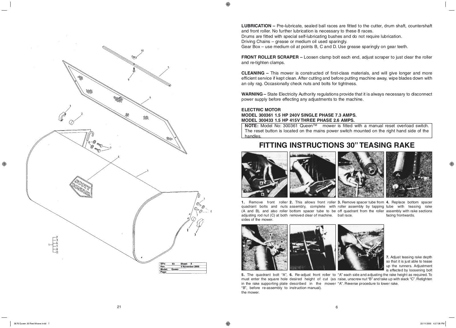
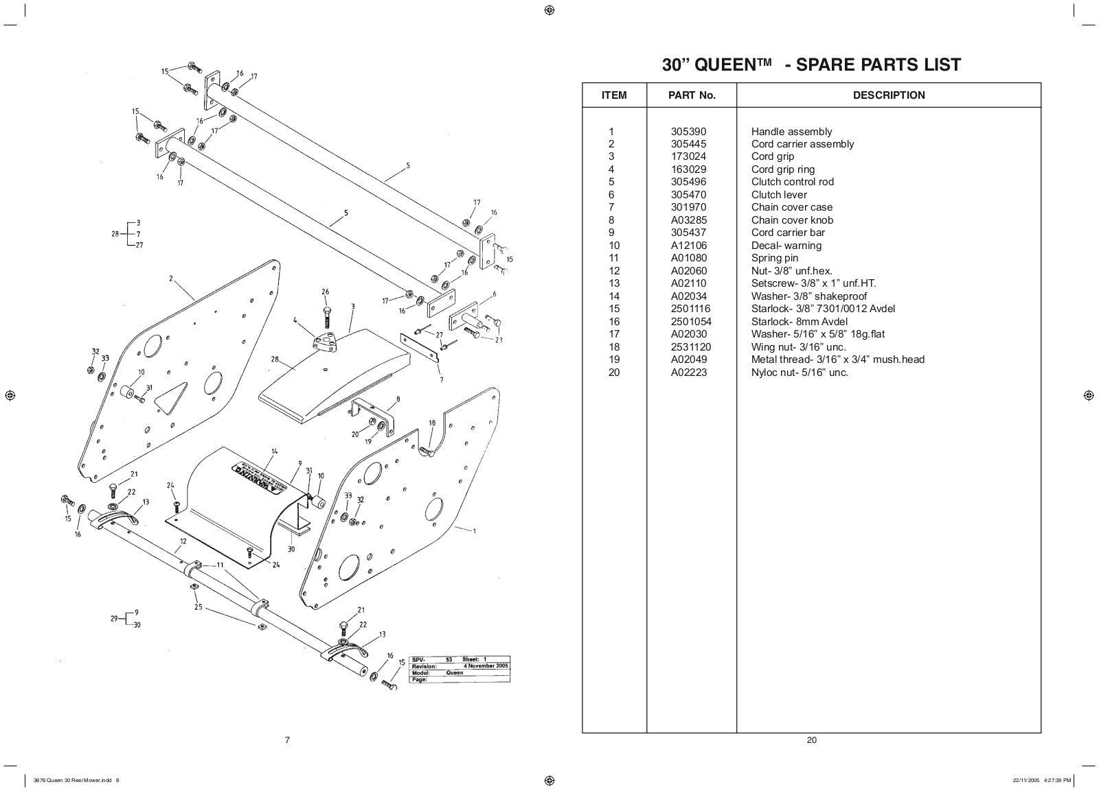
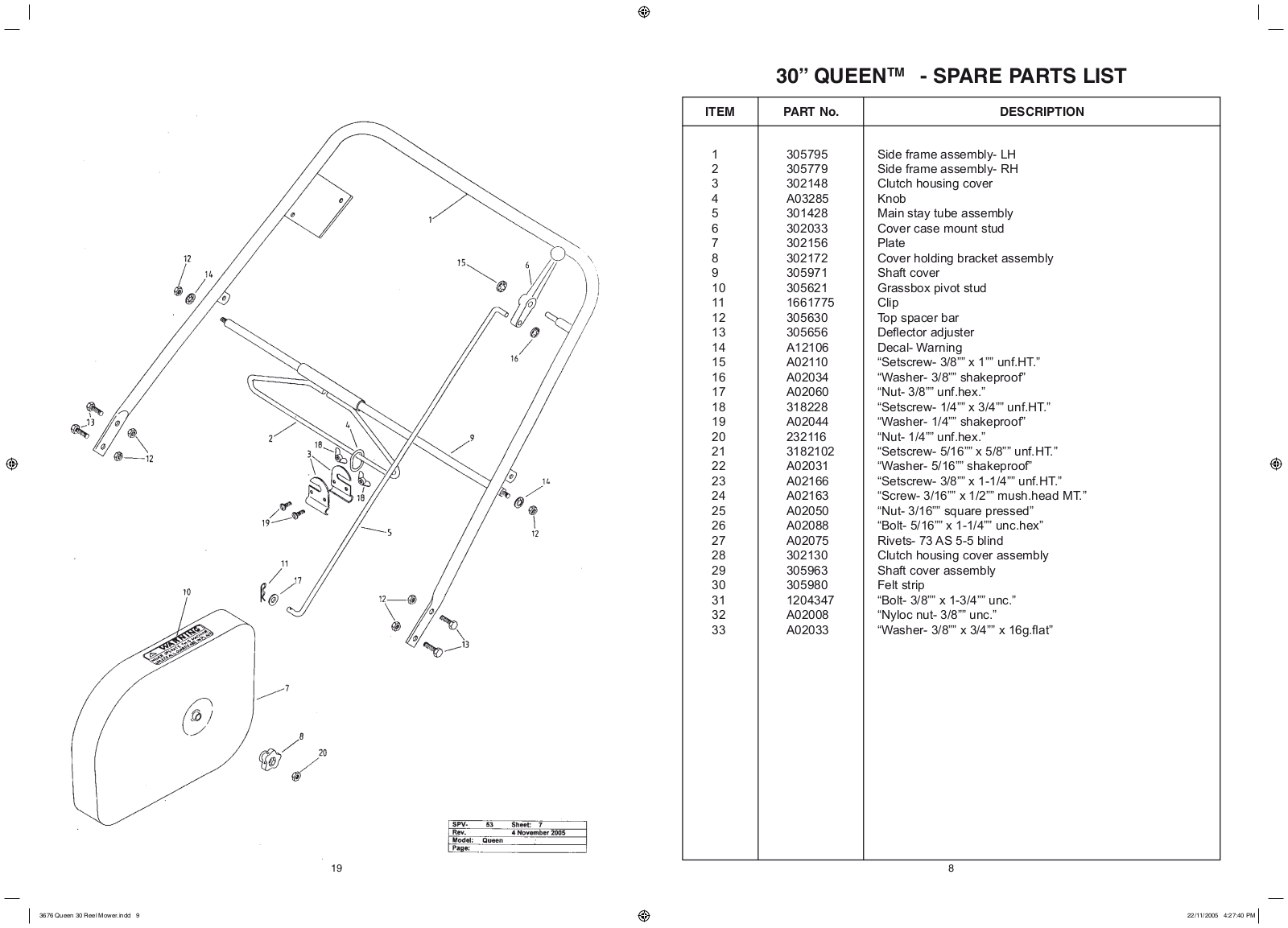
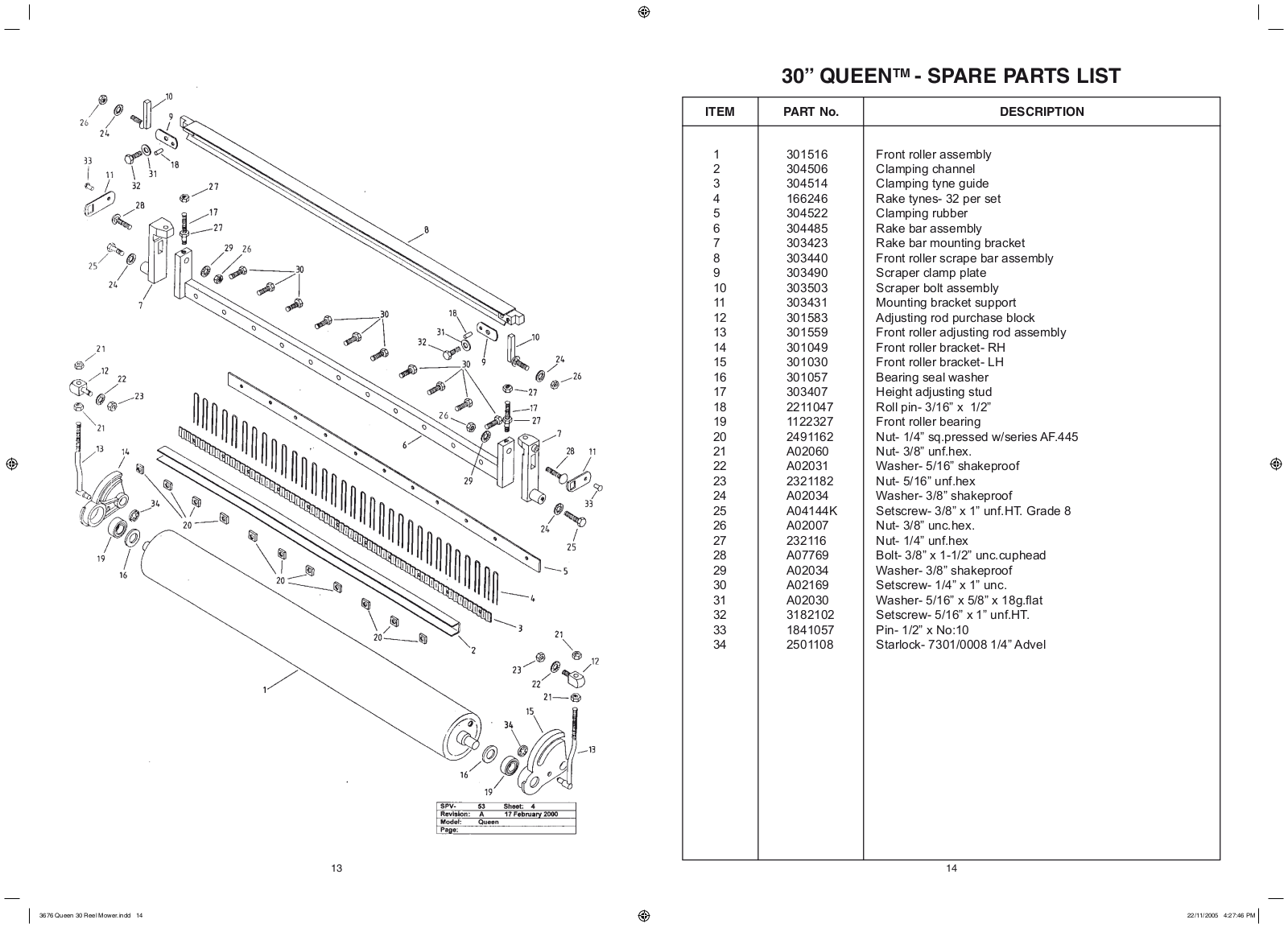
300361
300433
2
200 1998 Electric Diagrams
385002X108A
405012x108A
405606x108A
425621x108A
5377 - 12HP
75 (1998)
75 1999
75 (2000)
75 (2001)
75 (2002)
75 (2003)
75 (2004)
75 (2005)
80 - 22” (560mm)
214 1989 1995
Loading...
Loading...
Nothing found
300433
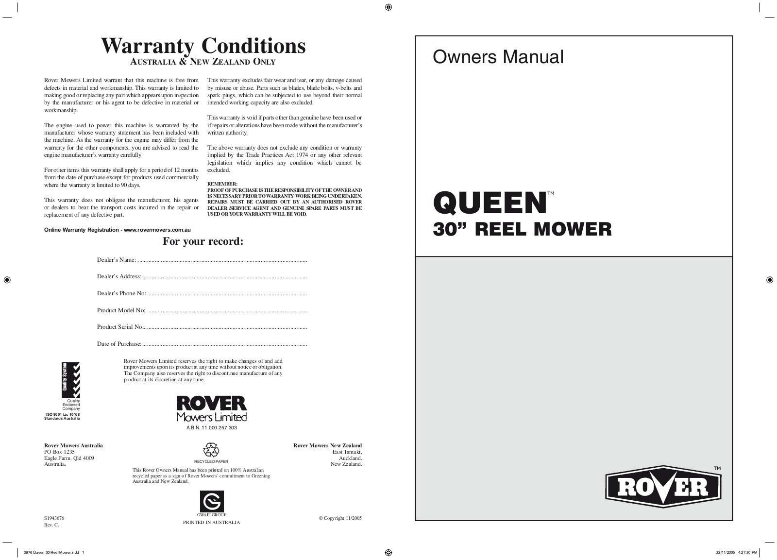
Owner's Manual
28 pgs
994.23 Kb
0
User Manual
28 pgs
948.32 Kb
0
Table of contents
Loading...
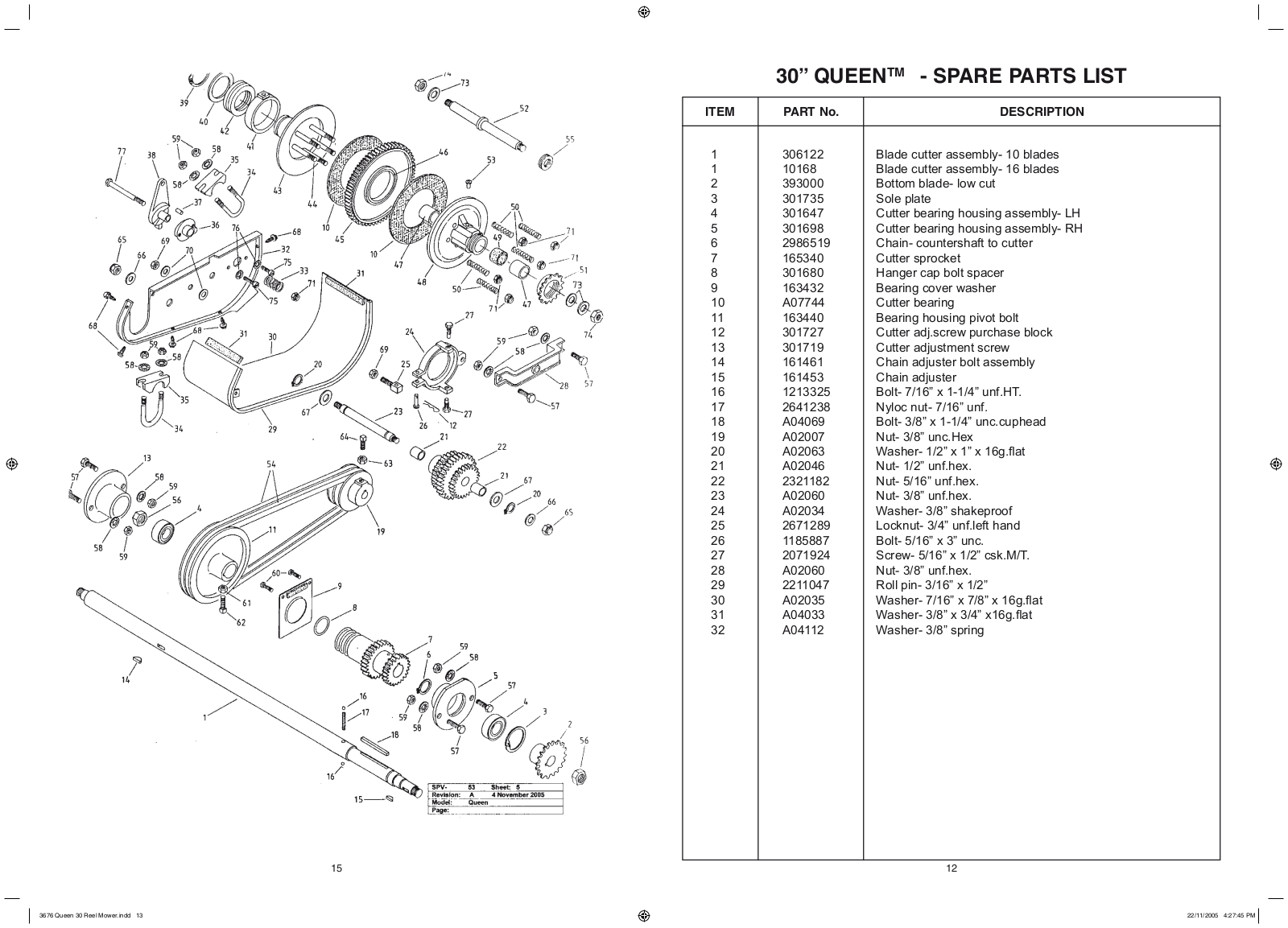
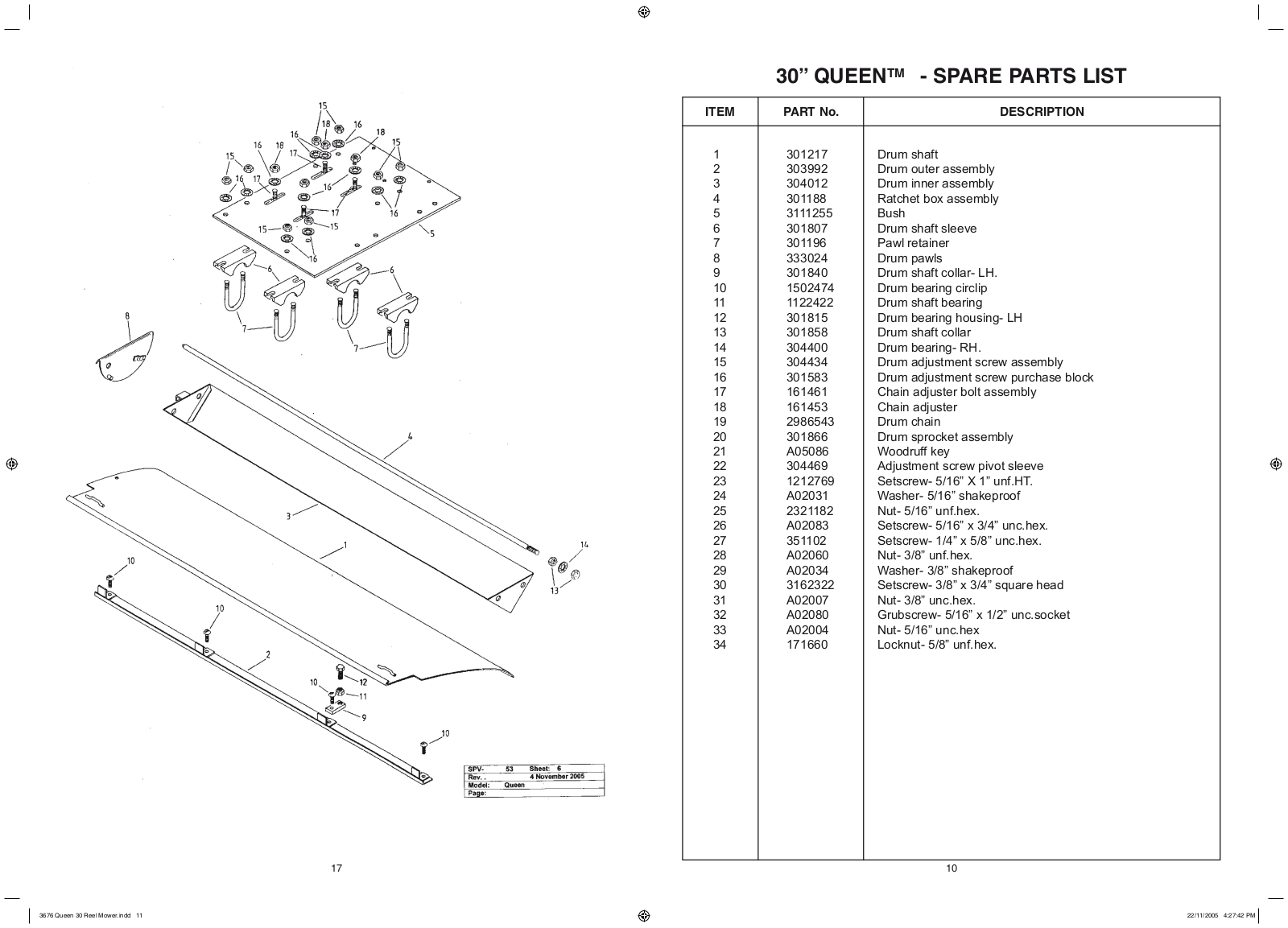
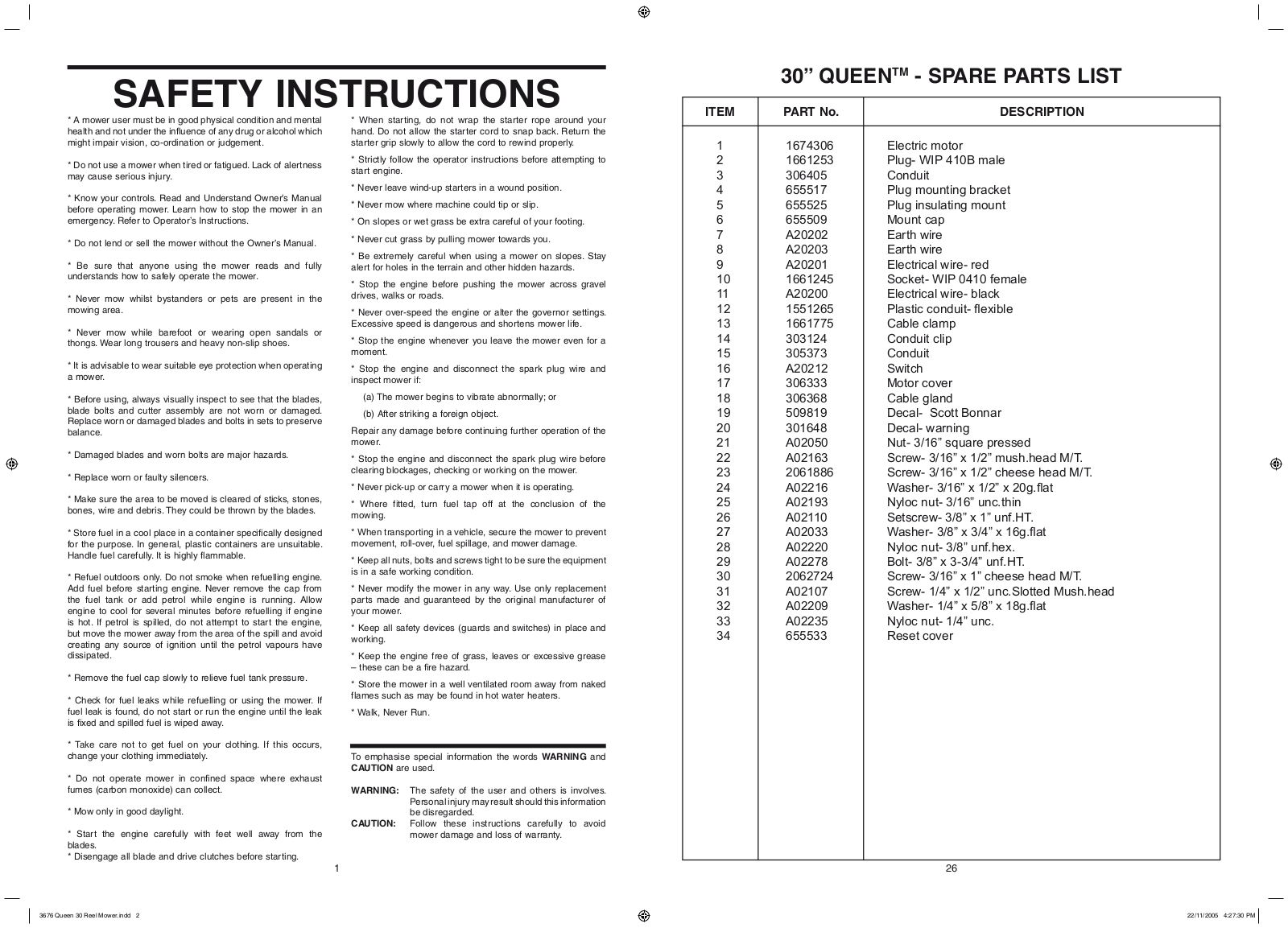
Rover 300433, 300361 User Manual
...
Rover User Manual
Download
Specifications and Main Features
Frequently Asked Questions
User Manual
Download
Loading...
+
hidden pages
Unhide
You need points to download manuals.
1 point = 1 manual.
You can buy points or you can get point for every manual you upload.
Buy points
Upload your manuals
 Loading...