

Page 1
Allen-Bradley
Dataliner DL40 Plus
Slave Displays
User
Cat. No. 2706-LV2S, -LV4S
Manual
Page 2
Important User Information
Because of the variety of uses for the products described in this
publication, those responsible for the application and use of this
control eq uipment must satisfy themselves that all necessary steps
have been taken to assure that each application and use meets all
performance and safety requirements, including any applicable laws,
regulations, codes and standards.
The illustrations, charts, sample programs and layout examples
shown in this guide are intended solely for purposes of example.
Since there are many variables and requirements associated with any
particular installation, Allen-Bradley does not assume responsibility
or liability (to include int ellectual property liability ) for actual use
based upon the examples shown in this publication.
Allen-Bradley publication SGI-1.1, Safety Guidelines for the
Application, Installation and Maintenance of Solid-State Control
(available from your local Allen-Bradley office), describes some
important differences between solid-state equipment and
electromechanical devices that should be taken into consideration
when applying products such as those described in this publication.
Reproduction of the contents of this copyrighted publication, in
whole or part, without written permission of Allen-Bradley
Company, Inc., is prohibited.
Throughout this manual we use notes to make you aware of safety
considerations:
ATTENTION: Identifies info rmation about practices
or circumstances that can lead to personal injury or
!
Attention statements help you to:
• identify a hazard
• avoid a hazard
• recognize the consequences
Important: Identifies information that is critical for successful
SLC, SLC 500, SLC 5/01, SLC 5/02, SLC 5/03, SLC 5/04, PLC and PLC-5 are registered trademarks of
Allen-Bradley, Inc.
death, property damage or economic loss.
application and understanding of the product.
Page 3

x-2
Page 4

Table of Contents
Preface
Overview of this Manual . . . . . . . . . . . . . . . . . . . . . . . . . . .P-1
Chapter Objectives . . . . . . . . . . . . . . . . . . . . . . . . . . . . . . .P-1
Intended Audience . . . . . . . . . . . . . . . . . . . . . . . . . . . . . . .P-2
Conventions Used . . . . . . . . . . . . . . . . . . . . . . . . . . . . . . . .P-2
Related Publications . . . . . . . . . . . . . . . . . . . . . . . . . . . . . .P-2
Introduction to the DL40 Plus
Slave
Setting the DIP Switches
Chapter 1
Chapter Objectives . . . . . . . . . . . . . . . . . . . . . . . . . . . . . . .1-1
Description . . . . . . . . . . . . . . . . . . . . . . . . . . . . . . . . . . . .1-1
Operating Modes . . . . . . . . . . . . . . . . . . . . . . . . . . . . . . . .1-2
DL (Dataliner) Slave Mode . . . . . . . . . . . . . . . . . . . . . . .1-2
PV (PanelView) Slave. . . . . . . . . . . . . . . . . . . . . . . . . . . .1-2
Terminal Mode . . . . . . . . . . . . . . . . . . . . . . . . . . . . . . . .1-2
Diagnostic Mode . . . . . . . . . . . . . . . . . . . . . . . . . . . . . .1-2
Features . . . . . . . . . . . . . . . . . . . . . . . . . . . . . . . . . . . . . .1-3
Typical Configurations . . . . . . . . . . . . . . . . . . . . . . . . . . . .1-4
DL40 Plus to DL40 Plus Slave . . . . . . . . . . . . . . . . . . . .1-4
PanelView to DL40 Plus Slave . . . . . . . . . . . . . . . . . . . .1-4
PLC, PC, or Other Device to DL40 Plus Slave. . . . . . . . . .1-4
Chapter 2
Chapter Objectives . . . . . . . . . . . . . . . . . . . . . . . . . . . . . . .2-1
DIP Switch Location . . . . . . . . . . . . . . . . . . . . . . . . . . . . . . 2-1
Selecting the Operating Mode . . . . . . . . . . . . . . . . . . . . . .2-2
Display Language . . . . . . . . . . . . . . . . . . . . . . . . . . . . . . .2-2
Baud Rate . . . . . . . . . . . . . . . . . . . . . . . . . . . . . . . . . . . . .2-2
Options . . . . . . . . . . . . . . . . . . . . . . . . . . . . . . . . . . . . . . .2-3
Serial Address . . . . . . . . . . . . . . . . . . . . . . . . . . . . . . . . . .2-3
Publication 2706-6.3
Page 5
tocii
Table of Contents
Installation and Startup
Chapter 3
Chapter Objectives . . . . . . . . . . . . . . . . . . . . . . . . . . . . . . . . . .3-1
Mounting the DL40 Slave . . . . . . . . . . . . . . . . . . . . . . . . . . . . .3-1
Panel Cutout Dimensions . . . . . . . . . . . . . . . . . . . . . . . . . . . . .3-2
Dimensions, 2-Line Display. . . . . . . . . . . . . . . . . . . . . . . . . . . .3-3
Dimensions, 4-Line Display . . . . . . . . . . . . . . . . . . . . . . . . . . .3-3
Electrical Precautions . . . . . . . . . . . . . . . . . . . . . . . . . . . . . . . .3-4
Input Voltage Requirements . . . . . . . . . . . . . . . . . . . . . . . . . . .3-4
Hazardous Location Installations . . . . . . . . . . . . . . . . . . . . . . .3-4
RS-232 Connections . . . . . . . . . . . . . . . . . . . . . . . . . . . . . . . .3-5
DL40 Slave to DL40 Plus Master RS-232 Port . . . . . . . . . . . .3-5
DL40 Slave to PanelView RS-232 Printer Port . . . . . . . . . . . .3-6
DL40 Slave to 1771-DB BASIC Module . . . . . . . . . . . . . . . . .3-6
DL40 Slave to PLC-5 Channel 0. . . . . . . . . . . . . . . . . . . . . . .3-7
DL40 Slave to SLC Channel 0 . . . . . . . . . . . . . . . . . . . . . . . .3-7
RS-485 Connections . . . . . . . . . . . . . . . . . . . . . . . . . . . . . . . .3-8
Connecting to a DL40 Master . . . . . . . . . . . . . . . . . . . . . . . .3-9
DL40 Slave to a Computer using an RS-485 Converter Box .3-10
Relay Connections . . . . . . . . . . . . . . . . . . . . . . . . . . . . . . . . .3-11
Power Connections . . . . . . . . . . . . . . . . . . . . . . . . . . . . . . . .3-12
Startup Sequence . . . . . . . . . . . . . . . . . . . . . . . . . . . . . . . . . .3-13
Dataliner (DL) Slave Mode
Chapter 4
Chapter Objectives . . . . . . . . . . . . . . . . . . . . . . . . . . . . . . . . . .4-1
Slave Mode Operation . . . . . . . . . . . . . . . . . . . . . . . . . . . . . . .4-1
Slave Mode Protocol . . . . . . . . . . . . . . . . . . . . . . . . . . . . . . . . .4-2
20 Characters for Display . . . . . . . . . . . . . . . . . . . . . . . . . . .4-2
Slave Address . . . . . . . . . . . . . . . . . . . . . . . . . . . . . . . . . . .4-2
Line Number . . . . . . . . . . . . . . . . . . . . . . . . . . . . . . . . . . . .4-2
Carriage Return . . . . . . . . . . . . . . . . . . . . . . . . . . . . . . . . . .4-2
Example Messages . . . . . . . . . . . . . . . . . . . . . . . . . . . . . . . . .4-3
Display Options . . . . . . . . . . . . . . . . . . . . . . . . . . . . . . . . . . . .4-3
[Ctrl][F] . . . . . . . . . . . . . . . . . . . . . . . . . . . . . . . . . . . . . . . . .4-3
[Ctrl][R] . . . . . . . . . . . . . . . . . . . . . . . . . . . . . . . . . . . . . . . .4-3
Clearing One or More Lines . . . . . . . . . . . . . . . . . . . . . . . . . . .4-4
Energizing Relay . . . . . . . . . . . . . . . . . . . . . . . . . . . . . . . . . . .4-4
Publication 2706-6.3
Page 6
Table of Contents
tociii
PanelView (PV) Slave Mode
Terminal Mode
Chapter 5
Chapter Objectives . . . . . . . . . . . . . . . . . . . . . . . . . . . . . . . . . .5-1
PV Slave Mode . . . . . . . . . . . . . . . . . . . . . . . . . . . . . . . . . . . . .5-1
PV Mode Protocol . . . . . . . . . . . . . . . . . . . . . . . . . . . . . . . . . . .5-1
Display Options . . . . . . . . . . . . . . . . . . . . . . . . . . . . . . . . . . . .5-2
[Ctrl][F](06 hex) . . . . . . . . . . . . . . . . . . . . . . . . . . . . . . . . . .5-2
[Ctrl][G](07 hex) . . . . . . . . . . . . . . . . . . . . . . . . . . . . . . . . . . 5-2
[Ctrl][L](0C hex) . . . . . . . . . . . . . . . . . . . . . . . . . . . . . . . . . .5-2
[Ctrl][M](0D hex) . . . . . . . . . . . . . . . . . . . . . . . . . . . . . . . . . .5-2
[Ctrl][R](12 hex) . . . . . . . . . . . . . . . . . . . . . . . . . . . . . . . . . .5-2
[Ctrl][J](0A hex) . . . . . . . . . . . . . . . . . . . . . . . . . . . . . . . . . .5-2
Line Display Characteristics . . . . . . . . . . . . . . . . . . . . . . . . . . .5-3
Line to line Delay. . . . . . . . . . . . . . . . . . . . . . . . . . . . . . . . . .5-3
Cursor Movement Delay . . . . . . . . . . . . . . . . . . . . . . . . . . . .5-3
Chapter 6
Chapter Objectives . . . . . . . . . . . . . . . . . . . . . . . . . . . . . . . . . .6-3
Terminal Mode Operation . . . . . . . . . . . . . . . . . . . . . . . . . . . . .6-3
Terminal Mode Protocol . . . . . . . . . . . . . . . . . . . . . . . . . . . . . .6-4
Cursor Up (Ctrl-K) . . . . . . . . . . . . . . . . . . . . . . . . . . . . . . . . .6-4
Cursor Down (Ctrl-V) . . . . . . . . . . . . . . . . . . . . . . . . . . . . . . .6-4
Cursor Left (Ctrl-H) . . . . . . . . . . . . . . . . . . . . . . . . . . . . . . . .6-4
Cursor Right (Ctrl-L) . . . . . . . . . . . . . . . . . . . . . . . . . . . . . . .6-4
Cursor Return (Ctrl-M) . . . . . . . . . . . . . . . . . . . . . . . . . . . . . .6-4
Line Feed (Ctrl-J). . . . . . . . . . . . . . . . . . . . . . . . . . . . . . . . . .6-4
Clear Screen (ESC and then *) . . . . . . . . . . . . . . . . . . . . . . .6-4
New Line (Ctrl-_). . . . . . . . . . . . . . . . . . . . . . . . . . . . . . . . . .6-5
Set Cursor Position (ESC,=,<row>,<column>) . . . . . . . . . . .6-5
Set Cursor Invisible (ESC . 0) . . . . . . . . . . . . . . . . . . . . . . . . .6-5
Set Cursor Visible (ESC . 1) . . . . . . . . . . . . . . . . . . . . . . . . . .6-5
De-energize Relay (ESC . 2). . . . . . . . . . . . . . . . . . . . . . . . . .6-5
Energize Relay (ESC . 3) . . . . . . . . . . . . . . . . . . . . . . . . . . . .6-5
Set Flashing Mode (ESC G 2) . . . . . . . . . . . . . . . . . . . . . . . . .6-5
Clear Flashing Mode (ESC G 0) . . . . . . . . . . . . . . . . . . . . . . .6-5
Monitor Mode (ESC U) . . . . . . . . . . . . . . . . . . . . . . . . . . . . . .6-6
Exit Monitor Mode (ESC u) or (ESC X). . . . . . . . . . . . . . . . . . .6-6
Display Status (ESC h) . . . . . . . . . . . . . . . . . . . . . . . . . . . . . .6-6
Diagnostic Mode
Chapter 7
Chapter Objectives . . . . . . . . . . . . . . . . . . . . . . . . . . . . . . . . . .7-1
Using the Diagnostic Mode . . . . . . . . . . . . . . . . . . . . . . . . . . . .7-1
Serial Port Settings . . . . . . . . . . . . . . . . . . . . . . . . . . . . . . . .7-1
Data Received Display . . . . . . . . . . . . . . . . . . . . . . . . . . . . .7-1
Data Errors . . . . . . . . . . . . . . . . . . . . . . . . . . . . . . . . . . . . . .7-2
Publication 2706-6.3
Page 7
tociv
Table of Contents
Specifications
Character Sets
Slave Address Settings
SLC/PLC Program Examples
Appendix A
Display Characters . . . . . . . . . . . . . . . . . . . . . . . . . . . . . . . . A-1
Electrical . . . . . . . . . . . . . . . . . . . . . . . . . . . . . . . . . . . . . . . A-1
Serial Communications . . . . . . . . . . . . . . . . . . . . . . . . . . . . A-1
Environmental . . . . . . . . . . . . . . . . . . . . . . . . . . . . . . . . . . . A-2
Mechanical . . . . . . . . . . . . . . . . . . . . . . . . . . . . . . . . . . . . . A-2
Certifications. . . . . . . . . . . . . . . . . . . . . . . . . . . . . . . . . . . . . A-2
Appendix B
ASCII (English) Character Set . . . . . . . . . . . . . . . . . . . . . . . . B-1
Extended ASCII Character Set . . . . . . . . . . . . . . . . . . . . . . . . B-2
Cyrillic Character Set . . . . . . . . . . . . . . . . . . . . . . . . . . . . . . B-3
International Character Set . . . . . . . . . . . . . . . . . . . . . . . . . . B-4
Appendix C
Appendix D
PLC-5 Channel 0 to DL40 Plus Slave . . . . . . . . . . . . . . . . . . D-1
SLC Channel 0 to DL40 Plus Slave . . . . . . . . . . . . . . . . . . . . D-2
Publication 2706-6.3
Page 8
Using this Manual
Preface
Chapter Objectives
Overview of this Manual
Read this chapter to fami liar iz e yoursel f with th e rest of the Datal iner
DL40 Plus Slave Message Display manual. You will learn about:
• contents of this manual
• intended audience
• conventions used
• related publications
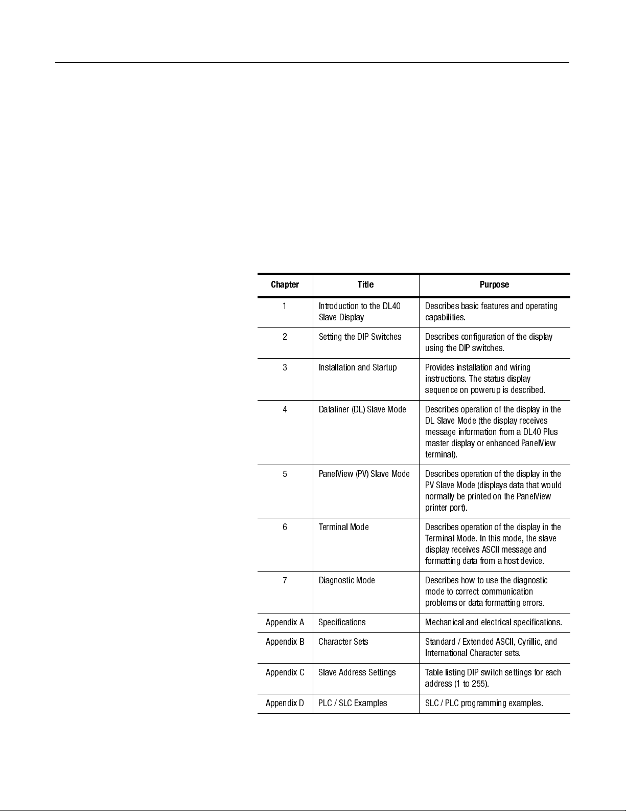
This manual describes how to install and use your DL40 Plus Slave
display. This manual contains the following:
Chapter Title Purpose
1 Introduction to the DL40
Slave Display
2 Setting the DIP Switches Describes configuration of the display
3 Installation and Startup Provides installation and wiring
4 Dataliner (DL) Slave Mode Describes operation of the display in the
Describes basic features and operating
capabilities.
using the DIP switches.
instructions. The status display
sequence on powerup is described.
DL Slave Mode (the display receives
message information from a DL40 Plus
master display or enhanced PanelView
terminal).
5 PanelView (PV) Slave Mode Describes operation of the display in the
PV Slave Mode (displays data that would
normally be printed on the PanelView
printer port).
6 Terminal Mode Describes operation of the display in the
Terminal Mode. In this mode, the slave
display receives ASCII message and
formatting data from a host device.
7 Diagnostic Mode Describes how to use the diagnostic
mode to correct communication
problems or data formatting errors.
Appendix A Specifications Mechanical and electrical specifications.
Appendix B Character Sets Standard / Extended ASCII, Cyrillic, and
International Character sets.
Appendix C Slave Address Settings Table listing DIP switch settings for each
address (1 to 255).
Appendix D PLC / SLC Examples SLC / PLC programming examples.
Publication 2706-6.3
Page 9
P-2
Preface
Intended Audience
Conventions Used
Related Publications
No specialized knowledge is required to configure and install the
DL40 slave display. However, we assume the following:
• The person responsible for equipment connections is familiar
with standard wiring practices and electrical codes in your area.
• Communication cabling is done by a person having an
understanding of basic communications terminology and cabling.
• Panel cutouts are made using the same methods and safety
practices followed for other panel mounted equipment.
The following conventions are used in this manual.
• The up caret, ^, may be used in place of [Ctrl] (Control key)
where space is limited.
• Values in a hexadecimal format have the suffix “hex”. For
example “B7 hex”.
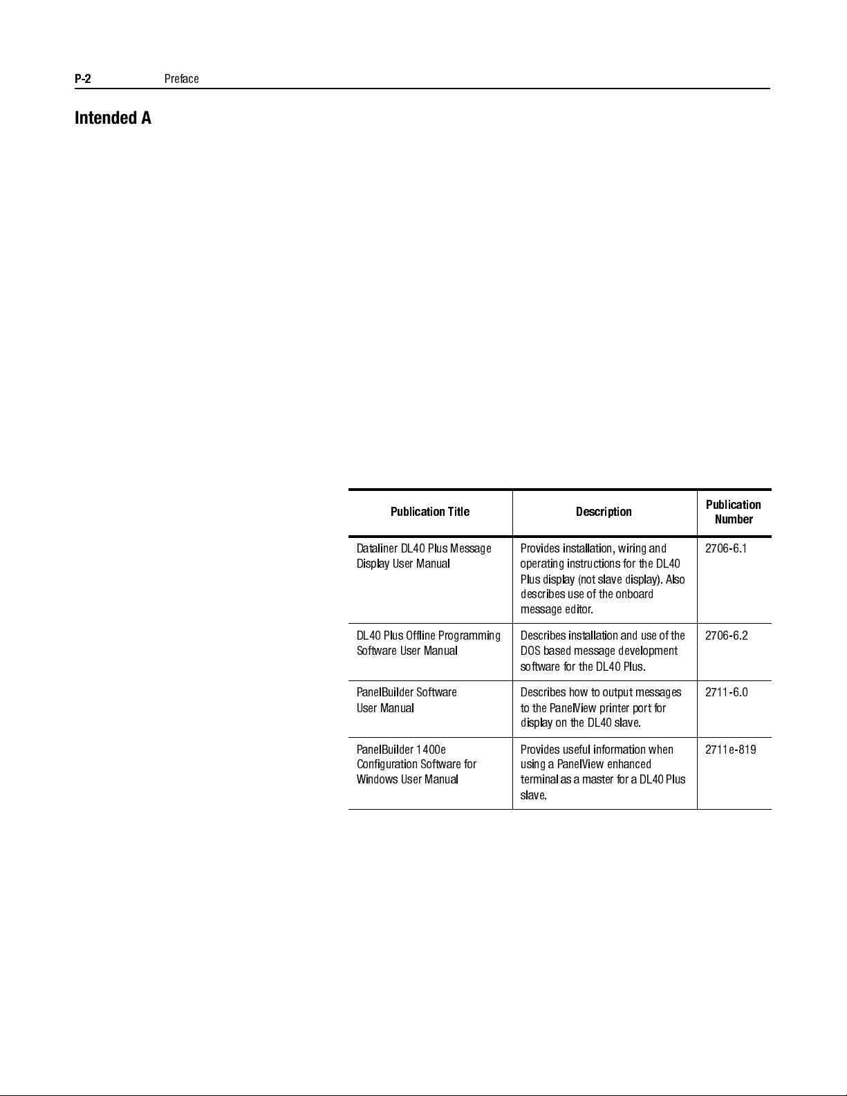
You may need to refer to the following related publications:
Publication Title Description
Publication
Number
Dataliner DL40 Plus Message
Display User Manual
DL40 Plus Offline Programming
Software User Manual
PanelBuilder Software
User Manual
PanelBuilder 1400e
Configuration Software for
Windows User Manual
Provides installation, wiring and
operating instructions for the DL40
Plus display (not slave display). Also
describes use of the onboard
message editor.
Describes installation and use of the
DOS based message development
software for the DL40 Plus.
Describes how to output messages
to the PanelView printer port for
display on the DL40 slave.
Provides useful information when
using a P anelView enhanced
terminal as a master for aDL40 Plus
slave.
2706-6.1
2706-6.2
2711-6.0
2711e-819
Publication 2706-6.3
Page 10
Chapter
Introduction to the DL40 Plus Slave
1
Chapter Objectives
Description
This chapter describes the DL40 Plus Slave display and summarizes
its capabilities. The follow ing topics are included in this chapter:
• DL40 Plus Slave description
• Operating modes
• Features
• Typical configurations
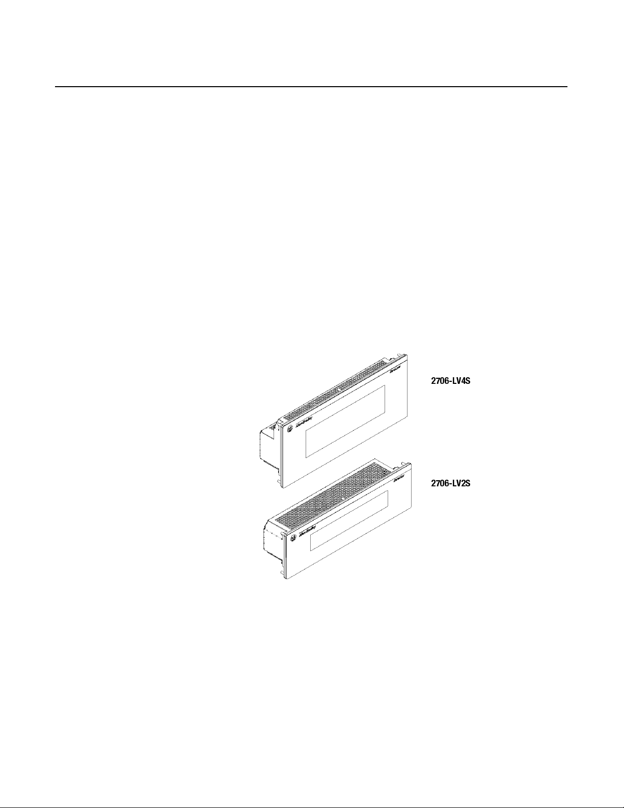
The DL40 Plus Slave displays are available in two-line and four-line
versions. These displays are designed for panel mounting in industrial
environments and require a 110-240V AC power source.
2706-LV4S
2706-LV2S
DL40 Plus Slave displays receive message text from a host device.
The host device may be a DL40 Plus master display, PanelView
terminal, programmable controller, or a personal computer. All
messages are created and stored in the host device.
The DL40 Plus Slave displays appear similar to the standard DL40
Plus two and four-line displays except they do not have front panel
buttons, indicator LEDs, keyboard port, or an RIO / parallel port.
Publication 2706.6.3
Page 11
1-2
Introduction to the DL40 Plus Slave
Operating Modes
The DL40 Plus Slave has four operating modes:
• DL Slave
•PV Slave
•Terminal
• Diagnostic
DL (Dataliner) Slave Mode
Use this mode when connecting the DL40 Plus Slave to a DL40 Plus
master display or an enhanced PanelView terminal such as the
PV1400e. One or more DL40 Plus Slaves may be connected to a
single DL40 Plus using an RS-485 link (mul tidrop) or an RS-232 link
(single drop only).
Each DL40 Plus Slave may be individual ly addressed to display only
the messages sent to a specific address. Displays with the same
address display the same messages. Addresses 13 and 18 are not
valid, see page 2-3.
PV (PanelView) Slave
Use this mode when connecting a single DL40 Plus Slave to the
printer port of a standard PanelView operator terminal (PV550, 600,
900, 1000 or 1400). The DL40 Plus Slave displays any text that
would normally be sent to a printer. The DL40 Plus Slave may be
connected to the PanelView using the RS-232 port. Only one display
may be connected on t he communi cati on link, t he DL40 P lus Slave is
not individually addressable in this mode.
Pu
blica
Terminal Mode
In this mode, the DL40 Plus Slave can receive data from any device
capable of sending serial ASCII characters. The ASCII characters
sent by the host device control the message text, line scrolling and
formatting of the messages. Only one display may be connected on
the communication link, the DL40 Plus Slave is not individually
addressable in this mode.
Diagnostic Mode
Use the diagnostic mode for basic setup and troubleshooting. In this
mode, the DL40 Plus Slave displays the hex value of all the data it
receives. An indication is provided if there is a communication error.
tion 2706-6.3
Page 12
Introduction to the DL40 Plus Slave
1-3
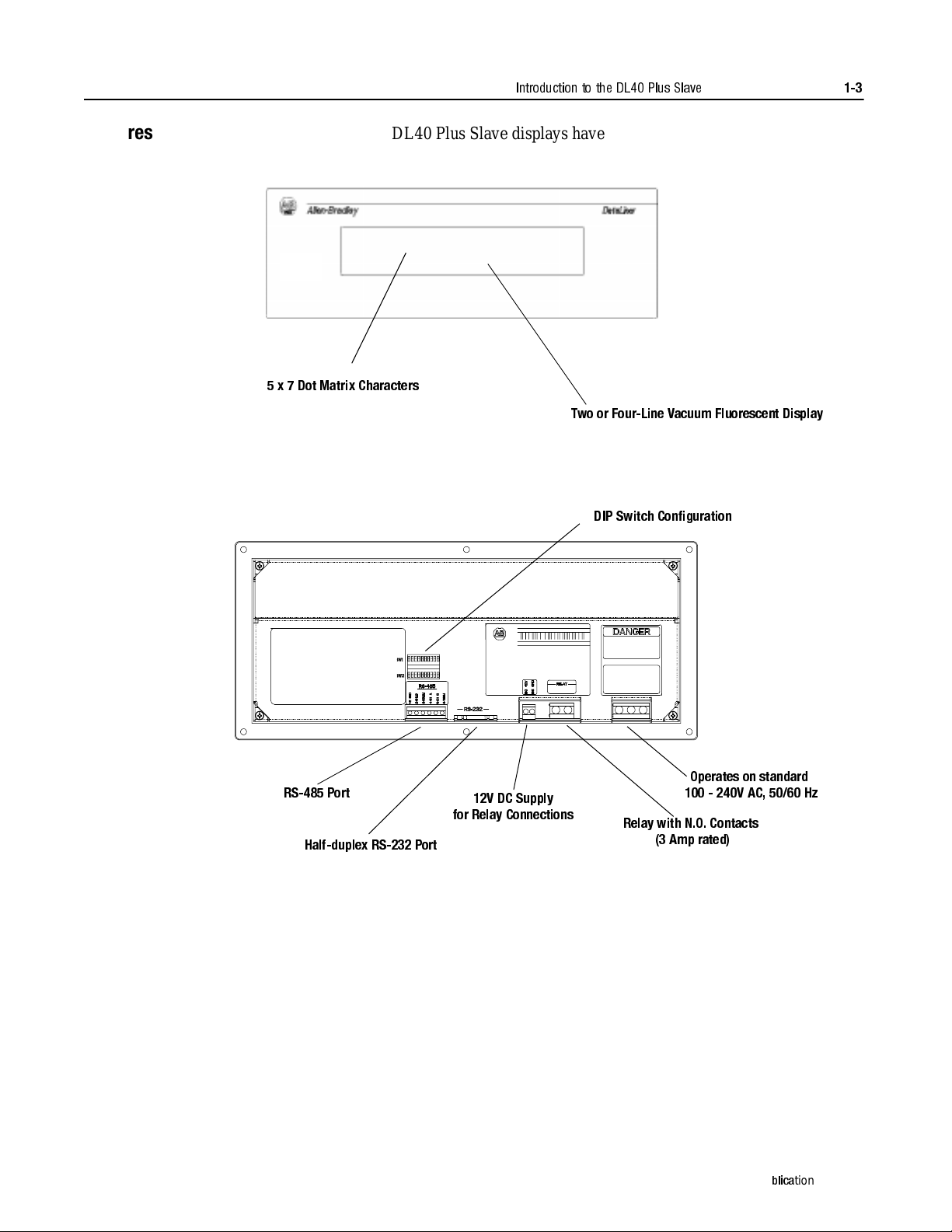
Features
DL40 Plus Slave displays have these features:
DL40 Plus
5 x 7 Dot Matrix Characters
Two or Four-Line Vacuum Fluorescent Display
DIP Switch Config uration
RS-485 Port
Half-duplex RS-232 Port
12V DC Supply
for Relay Connections
Operates on standard
100 - 240V AC, 50/60 Hz
Relay with N.O. Contacts
(3 Amp rated)
Pu
blica
tion 2706-6.3
Page 13
1-4
DL40 Plus (Master)
DL40 Plus S lave
DL40 Plus Slave
CHECK PRESS #1
PRESS #1 STOPPED
SYSTEM CHECK
NORMAL
RS-485(multidrop)
RS-232 (point-to-point)
Host Controller or Personal Computer
Triggering Messages
RS-485(multidrop)
Other Slaves
Other Slaves
DL40 Plus S lave
INLET VALVE CLOSED
RS-232
Printer Port
One Slave Only
(Not Individually Addressable)
12:48 09/16/98
DL40 Plus Slave
DL40 Plus S lave
RS-232 (point-to-point)
RS-485(multidrop )
PLC, Personal Computer,
or other device providing
ASCII message packets
Alarm Reset
6:40 AM 11/17/98
Tank Temperature:
150 F
Other Slaves
Other Slaves
Introduction to the DL40 Plus Slave
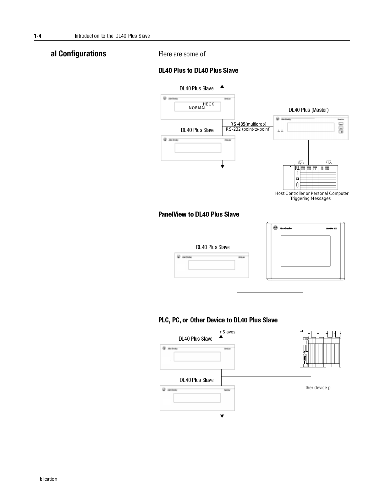
Typical Configurations
Here are some of the most typical applications:
DL40 Plus to DL40 Plus Slave
PanelView to DL40 Plus Slave
Pu
blica
tion 2706-6.3
PLC, PC, or Other Device to DL40 Plus Slave
Page 14
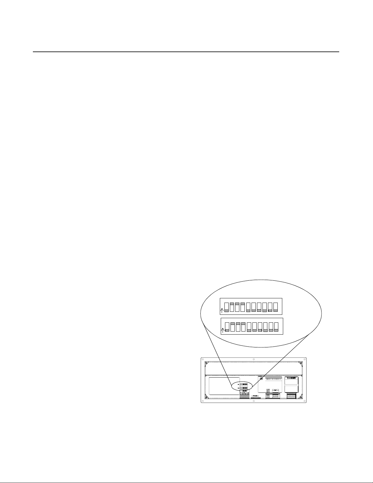
Setting the DIP Switches
10-Position DIP Switch
↑
Up = ON
↓
Down = OFF
N
O
12 34 567 8 910
N
O
1234 5678910
Chapter
2
Chapter Objectives
DIP Switch Location
This chapter describes ho w to conf igu re the DL40 Pl us Sla ve display
using the configuration DIP switches. The following topics are
provided:
• DIP switch location
• Selecting the operating mode
• Selecting display language
• Setting the baud rate
• Selecting display/communication options
• Setting display address
Access the 10-positi on DIP s witches from t he back of th e disp lay. Set
DIP switches using a thin nonconductive object. Do not use a pencil
(broken graphite pieces may short out the internal circuitry).
Changes to DIP switches take affect on powerup. If you make
changes with the power applied, you will have to cycle power before
the changes take effect.
Publication 2706-6.3
Page 15
2-2
Setting the DIP Switches
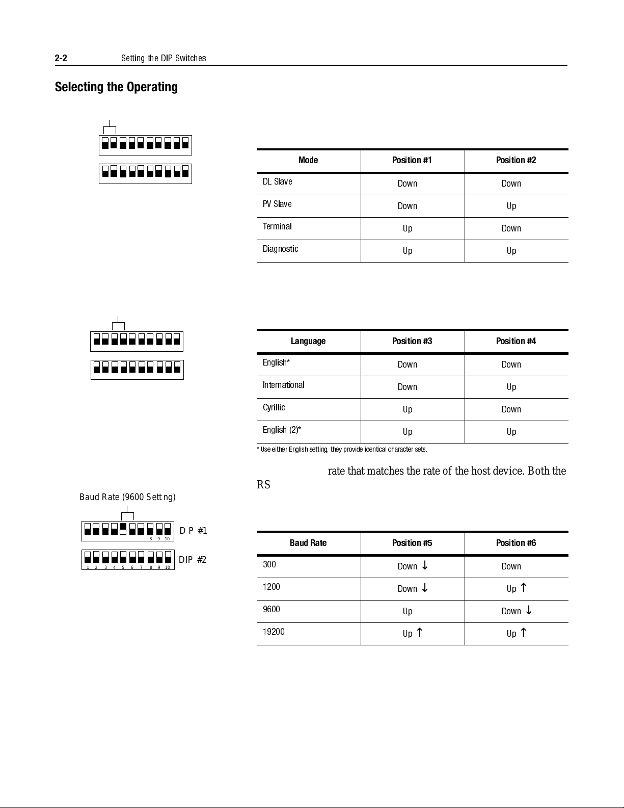
Selecting the Operating Mode
Mode (DL Slaves Setting)
12 3 45 67 8910
1234567 8910
DIP #1
DIP #2
Display Language
Language (English Setting)
1234567 8910
1234567 8910
DIP #1
DIP #2
The DL40 Plus Slave display operates in one of four modes. Chapter
1 briefly describes these modes. For detailed descriptions refer to the
individual chapters describing each mode. Select the mode using
position #1 and #2 of DIP Switch #1.
Mode Position #1 Position #2
DL Slave
PV Slave
Terminal
Diagnostic
Down
Down
Up
Up
↓
↓
↑
↑
Down
Up
Down
Up
↓
↑
↓
↑
The DL40 Plus Slave displays characters in one of three language
sets. Appendix B lists the characters in each of the language sets. Set
the display language using positions #3 and #4 of DIP Switch #1.
Language Position #3 Position #4
English*
International
Down
Down
↓
↓
Down
Up
↓
↑
Baud Rate
Baud Rate (9600 Setting)
1234567 8910
1234567 8910
DIP #1
DIP #2
Cyrillic
English (2)*
* Use either English setting, they provide identical character sets.
Up
Up
↑
↑
Down
Up
↓
↑
Select the baud rate that matches the rate of the host device. Both the
RS-232 and RS-485 ports are set at this rate. Set the rate using
positions #5 and #6 of DIP Switch #1. The DL40 Plus Slave displ ays
the currently set baud rate during its powerup sequence.
Baud Rate Position #5 Position #6
300
1200
9600
19200
Down
Down
Up
Up
↓
↓
↑
↑
Down
Up
Down
Up
↓
↑
↓
↑
Publication 2706-6.3
Page 16
Setting the DIP Switches
12 345 67 8910
32
44
Not Used
2-3
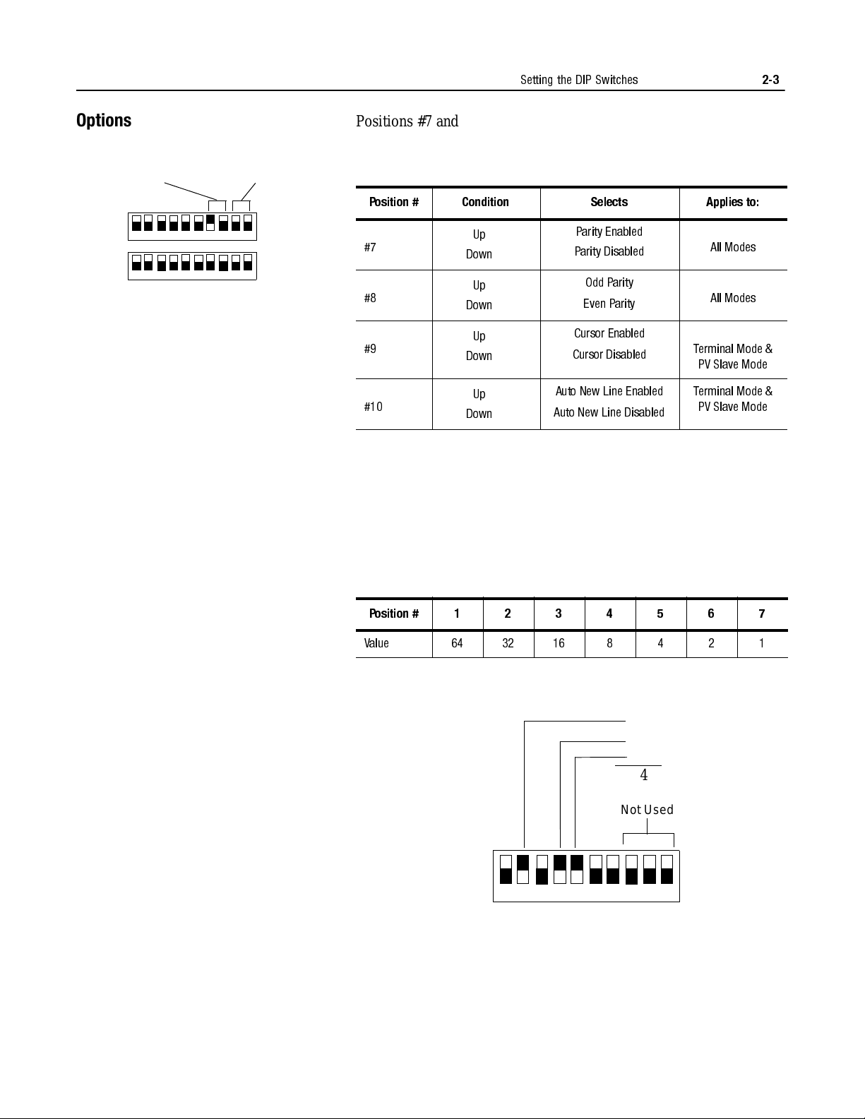
Options
Even P a rity Enab led
12345678910
12345678910
Serial Address
Cursor &
Auto New Line
Disabled
DIP #1
DIP #2
Positions #7 and #8 determine the parity, set the parity to match the
host device. Positio ns # 9 and #10 apply to Terminal mode operat io n,
Refer to Chapter 6.
Position # Condition Selects Applies to:
Parity Enabled
Parity Disabled
Odd Parity
Even Parity
Cursor Enabled
Cursor Disabled
Auto New Line Enabled
Auto New Line Disabled
All Modes
All Modes
Terminal Mode &
PV Slave Mode
Terminal Mode &
PV Slave Mode
#7
#8
#9
#10
Up
Down
Up
Down
Up
Down
Up
Down
↑
↓
↑
↓
↑
↓
↑
↓
Position #1 through #7 of DIP Switch #2 select the serial address of
the slave display. The address is the binary sum of the value of all of
the switches in the Up condition. Position #7 is the least significant
position (ones posi tion) a nd posit ion #1 has the most significa nt value
(64 position) as shown below. Positions #8 to #10 are not used.
Refer to Appendix C for a list of all possible addresses and the
corresponding switch positions.
Position # 1234567
Value 6432168421
For example, with Positions #2, #4, and #5 in the up condition, the
serial address is 44.
8
4
Important: Address 13 and 18 are invalid slave addresses. If you
assign either of these addresses to a slave, the slave overrides the
setting and internally switches the address to 127.
Publication 2706-6.3
Page 17

2-4
Setting the DIP Switches
Publication 2706-6.3
Page 18

Installation and Startup
Chapter
3
Chapter Objectives
Mounting the DL40 Plus Slave
This chapter describes how t o mount and make el ectr ical connect ions
to the DL40 Plus Slave display. The following topics are described:
• Mounting Instructions
• Panel Cutout Dimensions
• RS-232 Connections
• RS-485 Connections
• Relay Connections
• Power Connections
• Powerup Sequence
The following pages provide panel cutout dimensions and overall
dimensions for the DL40 Plus Slave displays.
You can also mount the DL40 Plus Slaves in a custom panel or
enclosure. When a DL40 plus is properly installed, the faceplate of
the DL40 Plus Slave provides a NEMA Type 12, 13, and 4X(indoor)
rating. To install the DL40 Plus Slave:
1. Cut and drill the appropriate mounting holes in the enclosure or
panel.
2. Remove the six mounting nuts from the hardware bag provided
with the di splay.
3. Position the DL40 Plus Slave in the panel or enclosure mounting
hole.
4. Install and alternately tighten the nuts to a torque of 10in
(1.13N
•
m).
•
lbs
Publication 2706-6.3
Page 19

3-2
Installation and Startup
Panel Cutout Dimensions
All dimensions are in inches (millimeters)
0.19 (4.8)
Cutout
3.50
(88.9)
0.19 (4.8)
6.81 (173.0)
6.94 (176.1)
Cutout
13.62 (345.9)
2-Line Slave Display
13.87 (352.3)
Cutout
13.62 (345.9)
3.88
(98.4)
0.25 (6.4)
Diameter Hole
6 places
0.19 (4.8)
Cutout
5.30
(134.6)
0.19 (4.8)
6.81 (173.0)
6.94 (176.1)
4-Line Slave Display
13.87 (352.3)
5.68
(144.3)
0.25 (6.4)
Diameter Hole
6 places
Publication 2706-6.3
Page 20

Dimensions
2-Line Display
4.38
(111.3)
Installation and Startup
13.16
(334.2)
3-3
14.357 (365.0)
Dimensions are in inches (millimeters)
Dimensions
4-Line Display
3.16
(80.3)
3.19
(81.0)
6.16
(156.4)
14.357 (365.0)
13.16
(334.2)
3.16
(80.3)
Dimensions are in inches (millimeters)
3.19
(81.0)
Publication 2706-6.3
Page 21

3-4
Installation and Startup
Electrical Precautions
Input Voltage Requirements
Install the DL40 Plus Slave display conforming to NFPA 70E,
Electrical Safety Requirements for Employee Workplaces. In addition
to the NFPA general guidelines, refer to the following:
Careful cable routing helps minimize electrical noise. Route
incoming power to the module by a separate path from the
communication cables.
Do not run communications wiring and power wiring in the
same conduit!
Where communication and wire paths must cross, make their
intersection perpendicular.
Grounding helps limit the effects of noise due to electromagnetic
interference (EMI). To avoid problems caused by EMI, properly
ground all equipment and use shielded cables.
Before connecting th e DL40 Plus S lave to t he incomin g power, verify
that the power source provides:
100-240 Volts AC, 50/60 Hz, 0.60 - 0.25 amperes
Hazardous Location Installations
Important: Power, input and output (I/O) wiring must be in
accordance with Class I, Division 2 wiring methods
[Article 501-4(b) of the National Electrical Code,
NFPA70] and in accordance with the local authority
having jur i sdiction.
ATTENTION: THIS EQUIPMENT IS SUITABLE
FOR USE IN CLASS I, DIVISION 2, GROUPS A, B,
!
!
!
C AND D, OR NON-HAZARDOUS LOCATIONS
ONLY.
ATTENTION: EXPLOSION HAZARD SUBSTITUTION OF COMPONENTS MA Y IMP AIR
SUITABILITY FOR CLASS 1, DIVISION 2.
ATTENTION: EXPLOSION HAZARD - DO NOT
CONNECT OR DISCONNECT EQUIPMENT
UNLESS POWER HAS BEEN SWITCHED OFF OR
THE AREA IS KNOWN TO BE NON-HAZARDOUS.
Publication 2706-6.3
Page 22

Installation and Startup
Pin # Function
1
2
3
4
5
6
7
8
9
TXD
RXD
Signal Common
No Connection
12
3
4
5
6789
No Connection
DSR
RTS
CTS
No Connection
DL40 Plus Slave
DL40 Plus Slave
DL40 Plus Master
2
3
5
2
3
5
TXD
RXD
Signal Ground
TXD
RXD
Signal Ground
3-5
RS-232 Connections
Use the RS-232 port to connect the DL40 Plus Slave to:
• DL40 Plus Master
• PanelView Printer Port
• 1771 or 1746-DB BASIC Module
• PLC-5 Chan nel 0
• SLC Channel 0
The following figure shows the location and terminal definitions for
the RS-232 port.
DL40 Plus Slave to DL40 Plus Master RS-232 Port
Connect a single DL40 Plus slave to a DL40 Plus master as shown
below. You can also use the DTAM Plus programming cable
(Catalog No. 2707-NC2) with a male-female pin adapter.
Publication 2706-6.3
Page 23

3-6
DL40 Plus Slave
2
3
5
2
3
5
TXD
RXD
Signal Ground
TXD
RXD
Signal Ground
PanelView 900 Shown
DL40 Plus Slave
5
6
20
2
3
5
TXD (RS-232 Out)
RXD (RS-232 In)
Signal Ground
3
7
4
1
2
BASIC Module
RS-232 Peripheral Port
Shield
TXD
RXD
Signal Ground
RTS
CTS
DSR
DTR
RS-232 Port
DL40 Plus Slave
6
7
8
2
3
5
TXD (RS-232 Out)
RXD (RS-232 In)
Signal Ground
3
4
5
1
2
BASIC Module
RS-232 PRT1 Port
Shield
RXD
TXD
COM
DTR
CTS
DSR
DTR
RS-232 Port
No Connection
Installation and Startup
DL40 Plus Slave to PanelView RS-232 Printer Port
Connect the DL40 Plus Slave to a PanelView RS-232 printer port as
shown below. The PanelView sends messages to the DL40 using its
print messages function. You can also use the DTAM Plus
programming cable (Catalog No. 2707-NC2) with a male-female pin
adapter.
DL40 Plus Slave to 1771-DB BASIC Module
Publication 2706-6.3
DL40 Plus Slave to 1746-BAS BASIC Module
Page 24

Installation and Startup
DL40 Plus Slave
6
4
5
2
20
7
8
3
PLC-5 Channel 0
25 Pin D Shell Connector
DCD
RXD
TXD
DTR
Common
DSR
RTS
CTS
RS-232 Port
1
Chassis Ground
6
7
8
3
4
5
1
2
9
Shield
No Connection
TXD
RXD
No Connection
Signal Common
DSR
RTS
CTS
No Connection
DL40 Plus Slave
6
7
8
3
4
5
1
2
SLC Channel 0
9-Pin Connector
DCD
RXD
TXD
DTR
Common
DSR
RTS
CTS
RS-232 Port
6
7
8
3
4
5
1
2
9
Shield
No Connection
TXD
RXD
No Connection
Signal Common
DSR
RTS
CTS
No Connection
3-7
DL40 Plus Slave to PLC-5 Channel 0
Connect the DL40 Plus Slave to a PLC-5 Channel 0 port as shown
below. You can also use programming cable (Catalog No. 2706NC12).
DL40 Plus Slave to SLC Channel 0
Connect the DL40 Plus Slave to an SLC Channel 0 port as shown
below. You can also use programming cable (Catalog No. 2706NC12).
.
Publication 2706-6.3
Page 25

3-8
Pin # Function
1
2
3
4
5
6
E GND
Shield
Common
Channel A
Channel B
Termination
RS-485
1-EGND
2-SHLD
3-COMM
4 - CHA
5 - CHB
6 - TERM
DL40 Plus Slave
Installation and Startup
RS-485 Connections
Use the RS-485 port to connect the DL40 Plus Slave to:
• DL40 Plus Master
• Personal Computer using an RS-485 Converter
The following figure shows the location and terminal definitions for
the RS-485 port.
Publication 2706-6.3
Page 26

Installation and Startup
3-9
Connecting to a DL40 Master
One or multiple DL40 Plus Slave displays may be connected to a
single DL40 Plus master display using the RS-485 port. The RS-485
network supports multi-drop communications with up to 126 slave
displays. Use Belden 9842 cable at a maximum length of 4,000 ft
(1219 meters). Refer to the following illustration.
DL40 Plus Master
User installed jumper at any node
(one node only) on the RS-485 link.
DL40 Plus Slave
GND
E
-
1
GND
E
-
1
RS-485
M
D
COM
SHL
-
-
3
2
RS-485
M
COM
SHLD
-
-
3
2
A
CH
-
4
A
CH
-
4
B
CH
-
5
B
CH
-
5
TERM
-
User installed jumper at first and
6
last Dataliner on the RS-485 link.
CH B
CH A
COM
Shield
Belden 984 2 Cable
Recommended
TERM
-
6
COM
CH A
CH B
CH B
CH A
COM
Shield
To N ext Node
Publication 2706-6.3
Page 27

3-10
(
)
y
Installation and Startup
DL40 Plus Slave to a Computer using an RS-485 Converter Box
If you are using a personal computer to send messages to the DL40
Plus Slave using the RS485 port, refer to the following diagram:
DL40-Plus Slave
Displa
- RS-485 Port
Term
CH-B
CH-A
Comm
Shield
E-Ground
6
5
4
3
2
1
Shield
Sheild
RS-485 Converter Box
Model LD-485A-MP
RXB
RXA
TXB
TXA
RS-485 OUT
2
3
7
RS-232 Ground
P.C. RS-232
RS-232 IN
Monitor
Computer
5- Ground
3- TXD
2- RXD
Serial Port
Note: When using the Black Box RS-485 Conver ter ( LD-485A-MP) :
• Set the RTS/CTS delay time to 5 millisec onds u si ng jumper
W9.
• Set Switch S2 to the unterminated position.
• If the RS-485 Driver Enable is set to “Enable When Data is
Received on the RS-232 Port” (Jumper W15 in the B-C
position), set the “Disable Timeout Delay” to 100 msec or
greater (Jumper W17) when communicating at lower Baud
rates (300 or 1200 Baud).
• You can use a programming cable (Catalog No. 2706NC15) to connect the computer serial port to the RS-485
converter box.
Publication 2706-6.3
Page 28

Installation and Startup
AC Power
May be required if Annunciator control
circuit requires a voltage source.
Fuse 3A Max
Recommended
Annunciator
DL40 Plus Slave
3-11
Relay Connections
Use the DL40 p lus slave relay to trigger a re mote alarm or warning
light. The relay has contacts rated at 3A at 250V AC. Connect the
remote alarm or light to the relay connectors on the back of the DL40
Plus Slave. Shown below is a typical wiring application.
ATTENTION:
Use the Alarm Relay for annunciator
purposes only. Do not use it for control circuits.
!
Publication 2706-6.3
Page 29

3-12
Green
(Green/Yellow)
White
(Blue)
L2NL1
Black
(Brown)
Installation and Startup
Power Connections
Before making power connection s, make sure that the po wer is turned
off. The DL40 Plus Sla ve requir es 100-240Volts AC, 50/60 Hz, 0.60 -
0.25 Amperes.
ATTENTION: Improper wiring of the power
connections may result in damage to the DL40.
!
Important: Make sure all DIP switch es are prop erly s et as descr ibed
in Chapter 2 before applying power.
Publication 2706-6.3
Page 30

Installation and Startup
DL40 PLUS SLAVE 2L
VER 1.00 (10/16/98)
DL SLAVE MODE
ENGLISH TEXT
DL SLAVE MODE
PV SLAVE MODE
TERMINAL MODE
DIAGNOSTIC MODE
ENGLISH
INTERNATIONAL TEXT
CYRILLIC TEXT
ENGLISH TEXT (2)
SERIAL ADDRESS: XXX
0to127
19200 BAUD (N-8-1)
19200
9600
1200
300
Parity / Data Bits / Stop Bits
N-8-1
E-7-1
O-7-1
CURSOR ENABLED
AUTO LINE ENABLED
CURSOR ENABLED
CURSOR DISABLED
AUTO LINE ENABLED
AUTO LINE DISABLED
3-13
Startup Sequence
When power is applied to the DL40 Plus Slave a powerup sequence
of displays are shown. The first display on powerup is the sign-on
banner identifying the hardware and firmware:
Following the sign-on banner, all of the display pixels are turned on
for 2 seconds followed by a series of informational messages
indicating the current DIP switch settings. Each display lasts for
about four seconds.
After the status messages are displayed, the DL40 Plus Slave clears
the display and enters the selected run mode.
Publication 2706-6.3
Page 31

3-14
Installation and Startup
Publication 2706-6.3
Page 32

Dataliner (DL) Slave Mode
Chapter
4
Chapter Objectives
Slave Mode Operation
This chapter describes the operation of the DL40 Plus Slave in DL
Slave Mode. This chapter contains the following topics:
• Slave mode description
• Slave mode protocol
• Example messages
• Display options
• Clearing one or more lines
• Energizing relay
Dataliner (DL) Slave mode allows multiple slave displays to display
different messages while connected to a single master device. Each
slave display is assigned an address and only displays messages sent
to that address. DL40 Plus Slaves assigned the same address display
the same messages. Me ssages sent to address 12 7 (global addres s) are
displayed on all slave displays reg ardless of the i r assigned address.
Note: If a DL40 Plus is used as a master display, make sure it is
configured for DL Slave protocol on it’s communication port (RS232 or RS-485).
DL Slave Mode is selected by DIP switch settings as described in
Chapter 2.
Publication 2706-6.3
Page 33

4-2
20 Characters
to Display
Slave
Address
Line
Number
Carriage
Return
Dataliner (DL) Slave Mode
Slave Mode Protocol
Messages sent to the DL40 Plus Slave in DL Slave mode must have
the followin g format:
If you are using a DL40 Plus as the master, configure its
communication port for DL Slaves (refer to the DL40 Plus user
manual, Publication 2706-6.1). This configures the DL40 master to
send message data in the DL Slave format.
20 Characters to Display
Send the message text characters to be displayed. ASCII characters
32 to 255 (20hex to FFhex) are supported. All control characters
within the mes sage text field, except [Ctrl][F] and [Ctrl][R], are
ignored. Any vali d AS CII ch ar act er, upper or l ower case can be sent.
If fewer than 20 c haract ers a re se nt, the re maining chara ct er posi tions
are filled with spaces. Refer to Appendix A for the character sets
available for t he selected language char act er set (DIP switch set ta ble,
see Chapter 2).
Slave Address
A one byte character from 1 to 127 (1 to 7F hex) that specifies the
address of the slave display that is to receive the message.
The following addresses are invalid:
• 13 (0Dhex) is invalid because it corresponds to Carriage Return
• 18 (12hex) is invalid because it corresponds to Ctrl-R
• If you select an invalid address, the DL40 overrides the setting
with an address of 127.
Address 127 is a global address that accepts all messages regardless
of the message’s address. In addition, any message sent with the
address 127 is received by all slave displays. Use address 127 for
messages you want displayed on all slaves instead of repeating the
same message to multiple displays.
Line Number
A one byte character specifying the line number the message is to be
displayed on. Valid line numbers are 1 to 4 decimal (not ASCII 1 to
4). Ctrl-A = 1, Ctrl-B = 2, Ctrl-C =3 and Ctrl-D = 4.
Carriage Return
Message is terminated by a carriage return, Ctrl-M (decimal 13,
0Dhex).
Publication 2706-6.3
Page 34

Dataliner (DL) Slave Mode
100 PRINT #”VALVE NUMBER 1 OPEN”, CHR(1), CHR(1), CHR(13)
Slave 1 Line 1
Carriage
Return
Carriage
Return
Valve Number 1 OPEN^A^A^M
Message Text
Slave #1
(01hex)
Line #1
(01hex)
4-3
Example Messages
For example, a print statement for a Catalog No. 1771-DB Basic
module with a DL40 Plus Slave display would be:
The message VALVE NUMBER 1 OPEN would be displa yed on line
one of slave number one. Note that to send the message fields, the
print CHR (decimal character equivalent) function is used.
To send the same message from any PC terminal program, use:
Display Options
Where ^A is the [Ctrl] and [A] keys pressed at the same time.
Use the following control codes in the message text for flash and reset
functions. Any other control codes are ignored.
[Ctrl][F]
This is the flash code. Send this code when you want the display
characters to flash. All characters following the first flash code in a
message flash. If two [Ctrl][F] codes appear in a message, only the
characters between the codes flash.
You can turn flash on and off multiple times in a message. At the start
of each new line of message text, the flash option is turned off. The
[Ctrl][F] character is not included in the 20 character limit of the
display protocol.
[Ctrl][R]
This is the reset co mmand. When a [Ctrl][R] is re ceived by the DL40
Plus Slave, all data for the current line is discarded. For example, if
10 characters are received by the DL40 Plus Slave and then a
[Ctrl][R] is sent, the 10 characters are discarded. After using the reset
command, you can start a new message. [Ctrl][R] resets the flash
status to non-flashing.
Publication 2706-6.3
Page 35

4-4
Slave
Address
Line
Number
Carriage
Return
Slave
Address
Line
Number
Carriage
Return
Dataliner (DL) Slave Mode
Clearing One or More Lines
Energizing Relay
To clear one or more lines on a DL40 Plus Slave, use:
The following table lists the line number byte required for clearing
any or all lines of the display.
Use this Byte for Line Number:
To Clear:
ASCII Equivalent Value
Line 1 [Ctrl][A] 1 decimal (1 hex)
Line 2 [Ctrl][B] 2 decimal (2 hex)
Line 3 [Ctrl][C] 3 decimal (3 hex)
Line 4 [Ctrl][D] 4 decimal (4 hex)
All Lines 2 50 decimal (32 hex)
To control the relay, use:
The following table indicates the line numbers to use for relay
control
:
Use this Byte for Line Number:
To:
ASCII Equivalent Value
Energize Relay 0 48 decimal (30 hex)
De-energize Relay 1 49 decimal (31 hex)
Publication 2706-6.3
Page 36

PanelView (PV) Slave Mode
Message Text (Up to 128 Characters)
Carriage
Return
Chapter
5
Chapter Objectives
PV Slave Mode
This chapter descri bes the o peration of the DL4 0 Plus Sla ve in the PV
Mode. The following topics are described:
• PV Slave Mode description
• PV Mode protocol
• Display options
Use the PanelView (PV) Slave Mode to send the DL40 Plus Slave
messages from a PanelView operator ter minal. The DL40 acts like a
printer attached t o the Pane lView communicati on port. Any messages
printed by the PanelView are displayed on the DL40 Plus Slave.
Note: In PV Mode, only one DL40 Plus Slave display can be
connected to the PanelView communication port (RS-232). In this
mode, DL40 Plus Slave displays cannot be addressed individually.
PV Slave Mode is selected by DIP switch settings as described in
Chapter 3. For information o n setting up a PanelView to print
messages, refer to the PanelBuilder Software user manual
(Publication 2711-6.0).
PV Slave Mode Protocol
Messages to the DL40 in PV mode consist of the following:
Only ASCII characters 32 to 255 (20hex to FFhex) are displayed.
ASCII characters 0 through 31 (1F hex) are non-printable control
characters.
T ext is displa yed from lef t to righ t. When the end of the cu rrent li ne is
reached, the cursor shifts and starts on the next line. If the display is
on the last line, the first line is cleare d and the lines are shifted u p.
Some control characters can be used to control the display of
messages (refer to display options, next section).
Publication 2706-6.3
Page 37

5-2
PanelView (PV) Slave Mode
Display Options
Use the following control codes to control the appearance of
messages displayed in PV Mode.
[Ctrl][F]
(06 hex)
Flash code. Send the [Ctrl][F] command when you want the display
characters to flash. All characters following the first flash code in a
message flash. If two [Ctrl][F] codes appear in a message, only the
characters between the codes flash.
You can turn flash on and off multiple times in a message. At the start
of each new line of message text, the flash option is turned off.
[Ctrl][G]
(07 hex)
This command energizes the DL40 Plus Slave relay. Display text is
not affected.
[Ctrl][L]
(0C hex)
Form feed code. Sending a [Ctrl][L] command clears the display and
moves the cursor to t he uppe r lef t cor ner of the d ispla y. Flash mode is
set to non-flashing. The relay is not affected.
[Ctrl][M]
(0D hex)
Carriage return command. Sending the [Ctr l][M] command
terminates the current message line, sets the flash mode to nonflashing, and moves the cursor to the beginning of the current line.
The relay is not affected.
If the Auto New Line DIP switch is enabled (see Chapter 2), the
cursor is also moved down to t he start of the next line. I f the cursor is
at the last line, the first line is cleared and the lines are shifted up.
Note: The cursor is not moved until the next displayable character is
received. This allows the current text to be displayed for the longest
period of time before being shifted or cleared.
[Ctrl][R]
(12 hex)
Relay reset comman d. Sending a [ Ctrl] [R] comman d de-ener gizes the
relay. Displayed text is unchanged.
[Ctrl][J]
(0A hex)
Line Feed command. Send a [Ctrl][J] command to move the cursor
down to the next line. If the cursor is on the last line, it remains on the
last line and all of the lines are shifted up (first line is removed).
Note: The cursor is not moved until the next displayable character is
received. This allows the current text to be displayed for the longest
period of time before being shifted or cleared.
Publication 2706-6.3
Page 38

PanelView (PV) Slave Mode
5-3
Line Display Characteristics
The PanelView Slave mode has two special display characteristics
that make messages easier to read:
Line to Line Delay
After each individual line is displayed, there is a one second pause
before the next line is displayed. This delay provides time for each
line to be read.
Cursor Movement Command Delay
Line wrap, carriage retur n, l ine fee d and f orm feed operations are not
executed immediately. These commands are stored and executed
only when the next displayable character (or identical cursor
movement) is received. This allows the current text to be displayed
for the longest period of time before being shifted or cleared.
Publication 2706-6.3
Page 39

5-4
PanelView (PV) Slave Mode
Publication 2706-6.3
Page 40

Terminal Mode
Chapter
6
Chapter Objectives
Terminal Mode Operation
This chapter describes the operation of the DL40 Plus Slave in
Terminal Mode. This chapter contains the following topics:
• Terminal mode operation
• Protocol
Terminal mode allows more control over messages than the basic
Slave Mode setting. In terminal mode, you can control:
• Cursor position
• Line scrolling
• Character-by-character display options
However, th is mode also requir es that you control the position ing and
formatting of each message. In Terminal Mode, only one DL40 Plus
Slave may be connected to the RS-485 or RS-232 link.
Terminal Mode is selected by DIP switch settings as described in
Chapter 2.
Publication 2701-6.3
Page 41

6-2
Terminal Mode
Terminal Mode Protocol
Message text and control codes are sent serially to the DL40 Plus
Slave in terminal mode. The following control codes are used:
Cursor Up (Ctrl-K )
(0B hex)
Positions the cursor directly above the current cursor position. If the
cursor is on the first line, the cursor is move d to the last line on the
display.
Cursor Down (Ctrl-V)
(16 hex)
Positions th e cursor directly below the current cursor position. If the
cursor is on the last line, the cursor is moved to the first line on the
display.
Cursor Left (Ctrl-H)
(08 hex)
Moves the cursor one position to the left of the current cursor
position. If the cursor is at th e leftmost position on a line, the cursor
is moved to the rightmost position on the line above. If the cursor is
at the leftmost position of the first line, the cursor is moved to the
rightmost position of the last line.
Cursor Right (Ctrl-L)
(0C hex)
Moves the cursor one position to the right of the current cursor
position. If th e curs or is at the ri ghtmost posi tion on a l ine, t he cur sor
is moved to the leftmo st posi t ion on t he ne xt lower line. If the cursor
is at the rightmost position of the last line, the cursor is moved to the
leftmost position of the first line.
Cursor Return (Ctrl-M)
(0D hex)
Moves the cursor to the leftmost position on the current line.
Line Feed (Ctrl-J)
(0A hex)
Moves the cursor directly below the current position. If the cursor is
on the last line, t he cursor stays in its posit ion an d every li ne is moved
up one line (first line is removed).
Reverse Line Feed (Esc
and then
J)
(1B, 4A hex)
Moves the cursor directly above the current position. If the cursor is
on the first line, the cursor stays in its position and every line is
moved down one line (last line is removed).
Cursor Home (Ctrl-T)
(14 hex)
Moves the cursor to the leftmost position on the first line of the
display.
Clear Screen (Esc
and then
*)
(1B, 2A hex)
Clears the display and moves the cursor to the leftmost position on
the first line of the display.
Publication 2706-6.3
Page 42

T erminal Mode
6-3
New Line (Ctrl-_)
(1F hex)
Moves the cursor to the beginning of the line below. If the cursor is
on the last line, every line is moved up one li ne and the bot tom line is
cleared.
Delete Line (Esc
and t he n
R)
(1B,52hex)
Clears the current line. The cursor remains at its current position.
Insert Line (Esc
and then
E)
(1B,45hex)
Moves the current line and all lines below it down one line (text on
bottom line is removed). Then clears the current line. The cursor
remains at its c urrent position.
Set Cursor Position (Esc,=,<row>,<column>)
(1B, 3D <r><c> hex)
Moves the cursor to the specified row and column. Refer to th e
following table. If you exceed the parameters listed in the table, the
cursor position defaults to the greatest row or column number.
Column 1234567891011121314151617181920
Row 1234
ASCII SP ! # $ % & ( ) * + , _ . / 0123
Decimal 32 33 34 35 36 37 38 39 40 41 42 43 44 45 46 47 48 49 50 51
Hex 20 21 22 23 24 25 26 27 28 29 2A 2B 2C 2D 2E 2F 30 31 32 33
For example, the following ASCII character sequence places the
cursor in Row 3, Column 9 of a four line display: ESC= “(
Set Cursor Invisible (ESC . 0)
(1B, 2E, 30 hex)
Makes the cursor invisible.
Set Cursor Visible (ESC . 1)
(1B, 2E, 31 hex)
Makes the cursor visible.
De-energize Relay (ESC . 2)
(1B, 2E, 32 hex)
De-energizes the annunciator relay.
Energize Relay (ESC . 3)
(1B, 2E, 33 hex)
Energizes the annunciator relay.
Publication 2706-6.3
Page 43

6-4
Terminal Mode
Set Flashing Mode (ESC G 2)
(1B, 47, 32 hex)
Enables flashing text mode. All characters received after this
command are displayed flashing until disabled with a Clear Flashing
Mode command.
Clear Flashing Mode (ESC G 0)
(1B, 47, 30 hex)
Disables flashing text mode.
Monitor Mode (ESC U)
(1B,55hex)
Displays all control codes as custom characters. These characters
represent the hexadecimal value of the control code. Any command
associated with the control code is ignored.
Exit Monitor Mode (ESC u) or (ESC X)
(1B,75hex)or(1B,58hex)
Exits Monitor Mode.
Display Status (ESC h)
(1B,68hex)
Displays the status of the display as defined by the DIP switches.
This is the same configuration te xt displ ayed on power up (see page 3-
13) without product version text and pixel test. After displaying the
status information, the screen is cleared with the cursor in the leftmost
position on the first line.
Publication 2706-6.3
Page 44

Diagnostic Mode
DIAG: 19200 N-8-1
19200
9600
1200
300
Baud Rate
Parity / Data Bits / Stop Bits
N - 8 - 1
E - 7 - 1
O - 7 - 1
DIAG: 19200 N-8-1
Slave 5, Line 1, Car riage Return
05 01 0D
Chapter
7
Chapter Objectives
Using the Diagnostic Mode
This chapter describes the operation of the DL40 Plus Slave in the
Diagnostic Mode. Use the diagnostic mode to ver ify communications
with a host device. Diagnostic mode displays the exact data being
sent by a host device. Use the diagnostic mode as a temporary
installation and troubleshooting aid.
Set the DL40 Plus Slave for diagnostic mode using the DIP switch
settings described in Chapter 2.
Serial Port Settings
In diagnostic mode, th e first line of the displa y indicates t he mode and
serial port configuration:
Data Received Display
Every byte received on ei ther th e RS-23 2 or RS-485 por t is dis pla yed
in a hexadecimal f orma t on l ine 2 of th e di splay. The bytes shift from
right to left as each new byte is received. The byte on the right is
always the last byte rece i ved. For example:
The value of every byte is displayed including control characters.
Characters are di splay ed as f ast as t hey are recei ved (n o buf f er). This
usually means that only the last 7 bytes of a long message are
viewable.
Publication 2706-6.3
Page 45
7-2
DIAG: 19200 N-8-1 !
05 01 0D
Serial Port Error
Diagnostic Mode
Data Errors
If the DL40 Plus Slave and host are not set to the same serial port
settings, a recept ion error occurs. The error symbol is a ! displaye d as
the last chara cte r on line 1. This sy mb ol is displayed for 1/5 sec (200
msec) after each serial error.
Note: Data cannot be displayed when a serial port error occurs.
Publication 2706-6.3
Page 46

Display Characters
Specifications
Character Height
Two line display
Four line display
Character Set
English
Cyrillic
International
Appendix
11.3 mm (0.44 inch)
11.3 mm (0.44 inch)
Standard & Extended ASCII Characters
Standard & Cyrillic (Russian) Characters
Standard & International ISO 8859-1
Characters
A
Electrical
Serial Communications
Characters per Display Line
Viewing Distance - Approximate
Character Type
Input Voltage
Input Power
Fuse Type
Annunciation Relay
AC Resistive Load
DC Resistive Load
Electrical Interface
Baud Rate
Data Format
20
7.6 meters (25 feet)
Vacuum fluorescent, 5 x 7 dot matrix
characters. Filtered to blue/green color.
100 - 240V AC, 50-60 Hz, 0.60 - 0.25A
60VA
Internal sealed (not user replaceable)
Single N.O. contact
3 Amperes at 240V AC
3 Amperes at 30V DC
RS-232 (EIA-/TIA-232-E)
RS-485 (EIA-485)
300, 1200, 9600, 19200
7 or 8 data bits; odd, even, or no parity
Publication 2706-6.3
Page 47

A-2
Specifications
Environmental
Mechanical
Certifications
Temperature Range - Operating
Temperature Range - Storage
Humidity
Shock
Vibration
Enclosure Type
Weight - Approximate
Catalog No. 2706-LV2S
Catalog No. 2706-LV4S
UL Listings
0°to 60°C (+32°to 140°F)
-40°to 85°C(-40°to 185°F)
5% to 95% (non-condensing)
Operating 15G, Non-operating 30G pulses
Operating 1.0G, Non-operating 2.5G
sinusoidal
UL listed for NEMAType 12, 13, 4, 4X(indoor
use only) when mounted in a suitable
enclosure of Type 12, 13, 4, 4X, IP65, or IP54
3.6 lbs. (1.6 kg)
4.8 lbs. (2.2 kg)
UL listed for UL-508 Industrial Control
Equipment Class I, Groups A, B, C, and D
Division 2, Hazardous Locations
European Union Directive
UL Listed for Canadian Safety Standards
CSA 22.2 No. 213
Electromagnetic Compatibility Directive
(89/336/EEC)
EN 50082-2
Generic Emission Standard -
Industrial Environment
EN 50081-2
Generic Immunity Standard -
Industrial Environment
IEC 1131-2 Programmable Controllers -
Euipment Class I
Publication 2706-6.3
Page 48
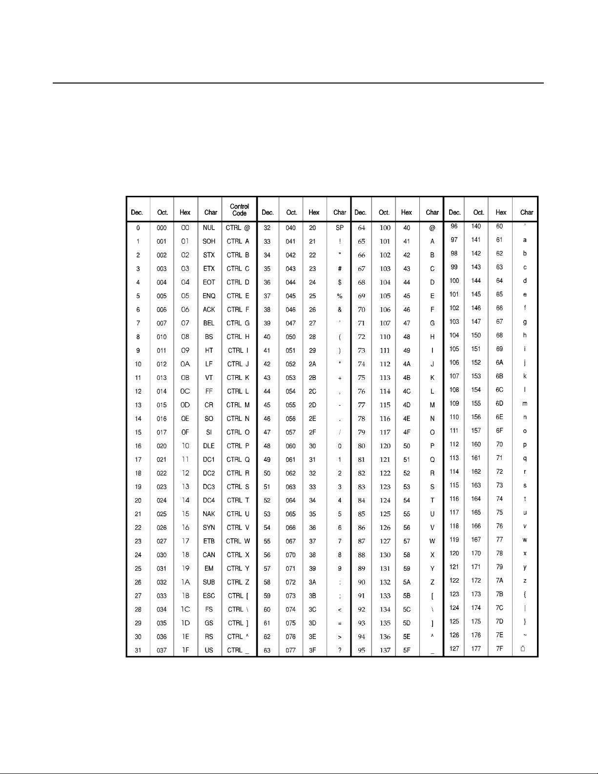
ASCII (English) Character Set
Character Sets
Appendix
B
Publication 2706-6.3
Page 49

B-2
Character Sets
Extended ASCII Character Set
The following extended ASCII characters are available with all character sets (English, International, and Cyrillic).
Publication 2706-6.3
Page 50

CharacterSets
B-3
Cyrillic Character Set
The Cyrillic character set is enabled when position #3 is On and
position # 4 is Off on DIP Switch 1.
Publication 2706-6.3
Page 51

B-4
Character Sets
International Character Set
The International chara cter s et is e nabl ed when pos itio n #3 is Off and
position # 4 is On (DIP Switch 1).
Publication 2706-6.3
Page 52

Slave Address Settings
Appendix
C
Address Address
00 OFF OFF OFF OFF OFF OFF OFF 38 OFF ON OFF OFF ON ON OFF
01 OFF OFF OFF OFF OFF OFF ON 39 OFF ON OFF OFF ON ON ON
02 OFF OFF OFF OFF OFF ON OFF 40 OFF ON OFF ON OFF OFF OFF
03 OFF OFF OFF OFF OFF ON ON 41 OFF ON OFF ON OFF OFF ON
04 OFF OFF OFF OFF ON OFF OFF 42 OFF ON OFF ON OFF ON OFF
05 OFF OFF OFF OFF ON OFF ON 43 OFF ON OFF ON OFF ON ON
06 OFF OFF OFF OFF ON ON OFF 44 OFF ON OFF ON ON OFF OFF
07 OFF OFF OFF OFF ON ON ON 45 OFF ON OFF ON ON OFF ON
08 OFF OFF OFF ON OFF OFF OFF 46 OFF ON OFF ON ON ON OFF
09 OFF OFF OFF ON OFF OFF ON 47 OFF ON OFF ON ON ON ON
10 OFF OFF OFF ON OFF ON OFF 48 OFF ON ON OFF OFF OFF OFF
11 OFF OFF OFF ON OFF ON ON 49 OFF ON ON OFF OFF OFF ON
12 OFF OFF OFF ON ON OFF OFF 50 OFF ON ON OFF OFF ON OFF
13 OFF OFF OFF ON ON OFF ON 51 OFF ON ON OFF OFF ON ON
14 OFF OFF OFF ON ON ON OFF 52 OFF ON ON OFF ON OFF OFF
15 OFF OFF OFF ON ON ON ON 53 OFF ON ON OFF ON OFF ON
16 OFF OFF ON OFF OFF OFF OFF 54 OFF ON ON OFF ON ON OFF
17 OFF OFF ON OFF OFF OFF ON 55 OFF ON ON OFF ON ON ON
18 OFF OFF ON OFF OFF ON OFF 56 OFF ON ON ON OFF OFF OFF
19 OFF OFF ON OFF OFF ON ON 57 OFF ON ON ON OFF OFF ON
20 OFF OFF ON OFF ON OFF OFF 58 OFF ON ON ON OFF ON OFF
21 OFF OFF ON OFF ON OFF ON 59 OFF ON ON ON OFF ON ON
22 OFF OFF ON OFF ON ON OFF 60 OFF ON ON ON ON OFF OFF
23 OFF OFF ON OFF ON ON ON 61 OFF ON ON ON ON OFF ON
24 OFF OFF ON ON OFF OFF OFF 62 OFF ON ON ON ON ON OFF
25 OFF OFF ON ON OFF OFF ON 63 OFF ON ON ON ON ON ON
26 OFF OFF ON ON OFF ON OFF 64 ON OFF OFF OFF OFF OFF OFF
27 OFF OFF ON ON OFF ON ON 65 ON OFF OFF OFF OFF OFF ON
28 OFF OFF ON ON ON OFF OFF 66 ON OFF OFF OFF OFF ON OFF
29 OFF OFF ON ON ON OFF ON 67 ON OFF OFF OFF OFF ON ON
30 OFF OFF ON ON ON ON OFF 68 ON OFF OFF OFF ON OFF OFF
31 OFF OFF ON ON ON ON ON 69 ON OFF OFF OFF ON OFF ON
32 OFF ON OFF OFF OFF OFF OFF 70 ON OFF OFF OFF ON ON OFF
33 OFF ON OFF OFF OFF OFF ON 71 ON OFF OFF OFF ON ON ON
34 OFF ON OFF OFF OFF ON OFF 72 ON OFF OFF ON OFF OFF OFF
35 OFF ON OFF OFF OFF ON ON 73 ON OFF OFF ON OFF OFF ON
36 OFF ON OFF OFF ON OFF OFF 74 ON OFF OFF ON OFF ON OFF
37 OFF ON OFF OFF ON OFF ON 75 ON OFF OFF ON OFF ON ON
1234567 1234567
Publication 2706-6.3
Page 53

C-2
Slave Address Settings
Address Address
1234567 1234567
76 ON OFF OFF ON ON OFF OFF 121 ON ON ON ON OFF OFF ON
77 ON OFF OFF ON ON OFF ON 122 ON ON ON ON OFF ON OFF
78 ON OFF OFF ON ON ON OFF 123 ON ON ON ON OFF ON ON
79 ON OFF OFF ON ON ON ON 124 ON ON ON ON ON OFF OFF
80 ON OFF ON OFF OFF OFF OFF 125 ON ON ON ON ON OFF ON
81 ON OFF ON OFF OFF OFF ON 126 ON ON ON ON ON ON OFF
82 ON OFF ON OFF OFF ON OFF 127 ON ON ON ON ON ON ON
83 ON OFF ON OFF OFF ON ON
84 ON OFF ON OFF ON OFF OFF
85 ON OFF ON OFF ON OFF ON
86 ON OFF ON OFF ON ON OFF
87 ON OFF ON OFF ON ON ON
88 ON OFF ON ON OFF OFF OFF
89 ON OFF ON ON OFF OFF ON
90 ON OFF ON ON OFF ON OFF
91 ON OFF ON ON OFF ON ON
92 ON OFF ON ON ON OFF OFF
93 ONOFFONONONOFFON
94 ONOFFONONONONOFF
95 ONOFFONONONONON
96 ON ON OFF OFF OFF OFF OFF
97 ON ON OFF OFF OFF OFF ON
98 ON ON OFF OFF OFF ON OFF
99 ON ON OFF OFF OFF ON ON
100 ON ON OFF OFF ON OFF OFF
101 ON ON OFF OFF ON OFF ON
102 ON ON OFF OFF ON ON OFF
103 ON ON OFF OFF ON ON ON
104 ON ON OFF ON OFF OFF OFF
105 ON ON OFF ON OFF OFF ON
106 ON ON OFF ON OFF ON OFF
107 ON ON OFF ON OFF ON ON
108 ON ON OFF ON ON OFF OFF
109 ON ON OFF ON ON OFF ON
110 ON ON OFF ON ON ON OFF
111 ON ON OFF ON ON ON ON
112 ON ON ON OFF OFF OFF OFF
113 ON ON ON OFF OFF OFF ON
114 ON ON ON OFF OFF ON OFF
115 ON ON ON OFF OFF ON ON
116 ON ON ON OFF ON OFF OFF
117 ON ON ON OFF ON OFF ON
118 ON ON ON OFF ON ON OFF
119 ON ON ON OFF ON ON ON
120 ON ON ON ON OFF OFF OFF
Publication 2706-6.3
Page 54

SLC/PLC Program Examples
Appendix
D
PLC-5 Channel 0 to DL40 Plus
Slave
PLC-5 Channel 0 to Dataliner DL40 Slave
in DL Slave Mode, PLC-5 in User-Mode
0000
String sent to DL40 Slave at serial address 01, line 01.
0001
This program assumes that the message text is entered in the string
file ST30:10. This file contains the message text and defines the
slave number and line number the mesage is to be displayed on.
Refer to page 4-3 for an example message.
TON
Timer On D elay
Timer T4:1
Time Base 0.01
Preset 50<
Accum 50<
AWT
ASCII Write
Channel 0
Source ST30:10
Control R6:25
String Length 22<
Characters Sent 22<
EN
DN
EN
DN
ER
String sent to DL40 Slave at serial address 01, Line 2.
T4:1
0002
DN
0003
AWT
ASCII Write
Channel 0
Source ST30:15
Control R6:20
String Length 23<
Characters Sent 23<
EN
DN
ER
END
Publication 2706-6.3
Page 55

D-2
SLC/PLC Program Examples
SLC Channel 0 to DL40 Plus Slave
Channel 0 of SLC connected to DL40 Slave operating in DL Slave mode.
This timer is used to continuously send ASCII data to the
DL40 slave display.
0000
This concatenate instruction allows the message text to be
entered separately from the control instructions. The string
text is entered in ST9:0 and the control instructions such as:
slave address, line number and carriage return is placed in ST9:1.
The two strings are then combined (in ST9:2) and sent out
channel 0 to the slave display.
0001
TON
Timer On Delay
Timer T4:0
Time Base 1.0
Preset 4<
Accum 0<
ACN
String Concatenate
Source A ST9:0
Source B ST9:1
Dest ST9:2
EN
DN
T4:0
0002
DN
Same as above, this instruction will send out two separate
messages one on each line if needed.
0003
T4:0
0002
DN
AWT
ASCII Write
Channel 0
Source ST9:2
Control R6:0
String Length 0<
Characters Sent 0<
ACN
String Concatenate
Source A ST9:3
Source B ST9:4
Dest ST9:5
AWT
ASCII Write
Channel 0
Source ST9:5
Control R6:1
String Length 0<
Characters Sent 0<
EN
DN
ER
EN
DN
ER
0003
Publication 2706-6.3
END
Page 56

Index
A
address
Dataliner slave mode 4-2
invalid adresses 2-3
settings C-1
alarm relay
connections 3-11
control of 4-4, 5-2, 6-3
specifications A-1
applications
DL40 master to Dl40 slave 1-4
PanelView to DL40 slave 1-4
PLC, PC, other device to DL40 slave 1-4
ASCII
character set B-1
extended characters B-2
audience P-2
B
baud rate 2-2
BASIC module
example 4-3
C
carriage return
Dataliner slave mode 4-2
PanelView slave mode 5-2
character sets B-1
clear lines 4-4
communications
data errors 7-2
displaying port settings 7-1
DL40 slave to DL40 master 3-9
DL40 slave to personal computer 3-10
setting baud rate 2-2
setting parity options 2-3
specifications A-1
connections
DL40 master to DL40 slave 1-4, 3-5
DL40 slave to 1746 BASIC module 3-6
DL40 slave to 1771 BASIC module 3-6
DL40 slave to PanelView printer port 3-6
DL40 slave to PLC-5 3-7
DL40 slave to SLC 3-7
electrical precautions 3-4
input power 3-4
PanelView to DL40 slave 1-4
PLC, PC, other device to DL40 slave 1-4
relay 3-11
RS-232 3-5
RS-485 3-8
conventions P-2
cutout
dimensions 3-2
Cyrillic characters B-3
D
data errors 7-2
Dataliner slave mode
carriage return 4-2
clearing one or more lines 4-4
display characters 4-2
display options 4-3
example messages 4-3
flash code 4-3
line number 4-2
operation 4-1
PLC-5 example D-1
protocol 4-2
relay control 4-4
reset command 4-3
slave address 4-2
SLC example D-2
description
DL40 slaves 1-1
diagnostic mode 1-2
data errors 7-2
displaying received data 7-1
serial port settings 7-1
dimensions
2-line display 3-3
4-line display 3-3
Publication 2706-6.3
Page 57

I2
Index
DIP switches
address settings 2-3, C-1
baud rate 2-2
selecting language 2-2
selecting operating mode 2-2
selecting options 2-3
display options
Dataliner slave mode 4-3
DL Slave Mode 1-2
E
electrical
DL40 slave to 1746 BASIC module 3-6
DL40 slave to 1771 BASIC module 3-6
DL40 slave to DL40 master 3-5, 3-9
DL40 slave to PanelView printer port 3-6
DL40 slave to personal computer 3-10
DL40 slave to PLC-5 3-7
power connections 3-4, 3-12
relay conections 3-11
electrical precautions 3-4
enclosure
rating A-2
EU
directives A-2
F
features
DL40 slave 1-2
I
installation
cutouts 3-2
electrical precautions 3-4
hazardous locations 3-4
instructions 3-1
international characters B-4
L
language
display characters 2-2
selecting 2-2
line feed 5-2
line number
Dataliner slave mode 4-2
M
mesages
Dataliner slave mode example 4-3
modes
dataliner slave 4-14-4
diagnostic 1-2, 7-17-2
DL slave 1-2
operating 1-2
PanelView slave mode 5-15-3
PV slave 1-2
selecting 2-2
terminal 1-2
terminal mode 6-16-4
flash code 4-3, 5-2
form feed
PanelView slave mode 5-2
H
hazardous locations
installing 3-4
humidity A-2
Publication 2706-6.3
mounting
dimensions 3-3
hazardous locations 3-4
instructions 3-1
N
NEMA
rating A-2
Page 58

Index
I3
O
operating modes 1-2
selecting 2-2
options
selecting 2-3
P
panel
cutout dimensions 3-2
PanelView slave mode
carriage return 5-2
cursor movement delay 5-3
display options 5-2
energize relay 5-2
flash code 5-2
form feed 5-2
line feed 5-2
line to line delay 5-3
relay reset 5-2
parity
setting 2-3
PLC
D-1
program example D-1
power
connections 3-12
requirements A-1
protocol
slave mode 4-2, 5-1
terminal mode 6-2
publications
related P-2
PV slave mode 1-2
R
relay
connections 3-11
control of 4-4, 5-2
specifications A-1
reset command 4-3
RS-232
connector 3-5
to 1746 BASIC module 3-6
to 1771 BASIC module 3-6
to PanelView printer port 3-6
to PLC-5 3-7
to SLC 3-7
RS-485
connecting to DL40 master 3-9
converter box 3-10
to DL40 master 3-9
to personal computer 3-10
S
serial address
setting 2-3
switch settings C-1
serial communications
specifications A-1
shock A-2
slave address
Dataliner slave mode 4-2
settings C-1
SLC
program example D-2
specifications A-1
switches
see DIP switches 2-1
T
temperature
operating ranges A-2
terminal mode 1-2
clear screen 6-2
cursor down 6-2
cursor home 6-2
cursor left 6-2
cursor return 6-2
cursor right 6-2
cursor up 6-2
de-energize relay 6-3
Publication 2706-6.3
Page 59

I4
Index
delete line 6-3
display status 6-4
energize relay 6-3
flashing mode 6-4
insert line 6-3
line feed 6-2
monitor 6-4
new line 6-3
reverse line feed 6-2
set cursor invisible 6-3
set cursor position 6-3
set cursor visible 6-3
U
UL
listing A-2
V
vibration A-2
viewing distance A-1
voltage
input requirements 3-4, A-1
Publication 2706-6.3
Page 60

Publication 2706-6.3 - December 1998 41061-096-01(A)
© (1998) Rockwell International Corporation. Printed in the U.S.A.
 Loading...