

Page 1

2705-DN42
DeviceNet Interface Communication Board
Installation Instructions
This document describes how to install a DeviceNet communications
board.
Overview
LED Indicator
•
• DIP Switches
• DeviceNet Connections
• DeviceNet Components
Installation and Mounting
Setting the DIP Switches
•
• DeviceNet Termination
Operations
Modes of Operation
•
• DeviceNet Operations
Troubleshooting
Using the LED Indicator
•
User-Defined Configuration
For more information on the RediSTATION Operator Terminal and
its DeviceNet Configuration refer to Publication 2705-804 on–line at
htpp://www.ab.com.
For more information on the DeviceNet specifications, refer to the
Open DeviceNet Vendor Association at http://www.odva.ors.
Page 2
2
Overview
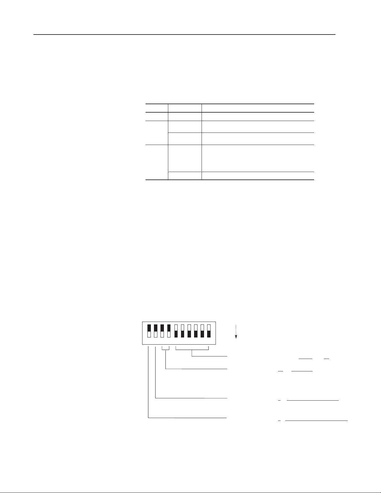
LED Indicator
DIP Switches
The RediSTATION has one bicolor LED (red/green) to show its
operating status. The LED shows the following indications.
Color State Indication
None Off No power.
Solid Unrecoverable fault.
Red
Green
Flashing
Solid Normal runtime operation.
Flashing Device is idle or not allocated to a master.
Output error or configuration error.
The RediSTATION device is operating as a slave to
the master controller.
The LED is visible when the cover of the enclosure is removed.
The RediSTATION has one 10-position DIP switch for setting:
• DeviceNet Node Address
• DeviceNet Data Rate
• Output Fault State (Off or Last State)
• Output Flash Rate
The DIP switch is located on the circuit board inside the enclosure.
The switch settings and functions are shown below. The default
setting for each switch or group of switches is underlined.
Default Configuration
OFF = 0
10 123456789
ON = 1
DeviceNet Address 000000 – 111111
DeviceNet Data Rate 00
Output Fault State 0 = Outputs Turn Off on Fault
Output Flash Rate 0 = 1 Hz (0.5 sec On, 0.5 sec Off)
= 125K BPS
01 = 250K BPS
10 = 500K BPS
11 = Invalid
1 = Outputs Hold Last State on Fault
1 = 2 Hz (0.25 sec On, 0.25 sec Off)
(0 to 63)
Page 3
3
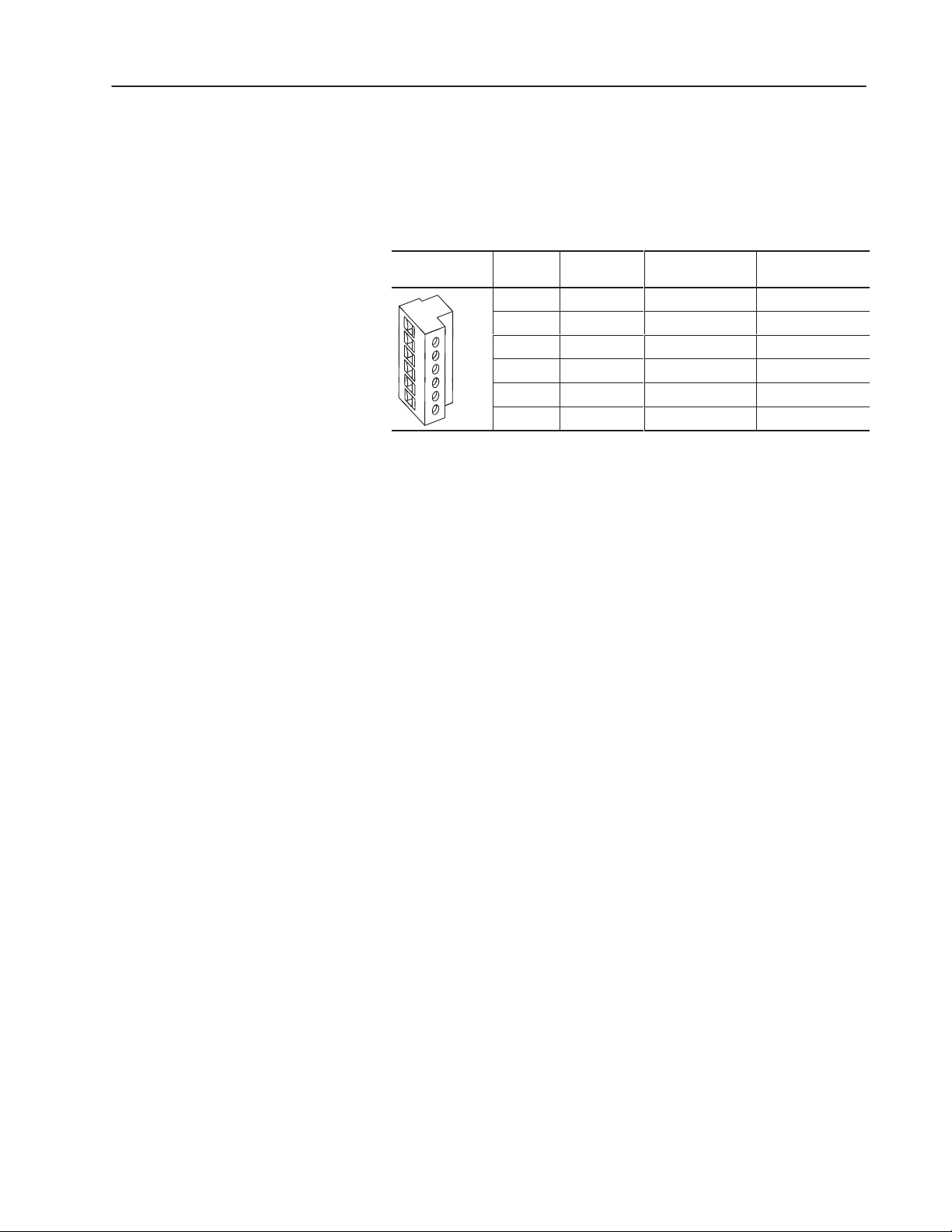
DeviceNet Connection
DeviceNet Components
The RediSTATION receives all power and communications through
the DeviceNet cable. A separate power supply is not required. This
is the only external connection to the RediSTATION.
The RediSTATION connects to the DeviceNet using the DeviceNet
terminal block on the communication board.
DeviceNet
Terminal Block
Terminal Signal Function Color
1 COM Common Black
2 CAN_L Signal Low Blue
1
6
3 SHIELD Shield Uninsulated
4 CAN_H Signal High White
5 VDC+ Power Supply Red
6 E. GND Chassis Ground Green
DeviceNet cables and components are available from Allen-Bradley
as separate catalog numbers.
It is your responsibility to install and implement the DeviceNet
network and supported devices according to the DeviceNet
guidelines.
Page 4
4
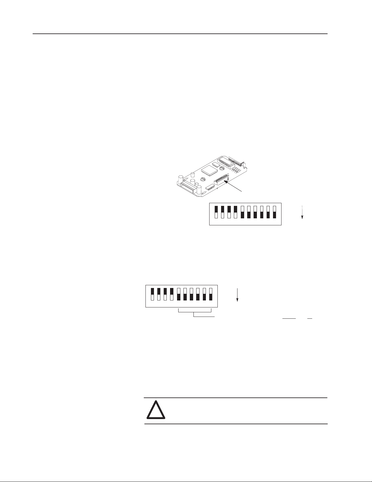
Installation and Mounting
Setting the DIP Switches
The setting of the DIP switch on the circuit board determines:
• DeviceNet node address
• DeviceNet data rate
• Output flash rate
• Output fault state
The location of the DIP switch and the factory defaults are shown
below.
DIP Switches
OFF = 0
10 123456789
ON = 1
Setting the DeviceNet Node Address
DIP switches 1 to 6 set the node address (0 to 63) of the
RediSTATION on the DeviceNet network. The address is set using
binary addressing.
OFF = 0
10 123456789
ON = 1
DeviceNet Address 000000 – 111111 (0 to 63)
The table below shows the switch settings for each address (0 to 63).
To set the DeviceNet node address:
1. Refer to the table below for switch settings of a specific address.
2. Using your finger or a pointed object, slide switches 1 through 6
to the appropriate ON/OFF positions.
ATTENTION: Do not use a pencil. Graphite from the pencil
is conductive and may damage the DIP switch.
!
Page 5
5
DeviceNet
Address
0 000000 16 010000 32 100000 48 110000
1 000001 17 010001 33 100001 49 110001
2 000010 18 010010 34 100010 50 110010
3 000011 19 010011 35 100011 51 110011
4 000100 20 010100 36 100100 52 110100
5 000101 21 010101 37 100101 53 110101
6 000110 22 010110 38 100110 54 110110
7 000111 23 010111 39 100111 55 110111
8 001000 24 011000 40 101000 56 111000
9 001001 25 011001 41 101001 57 111001
10 001010 26 011010 42 101010 58 111010
11 001011 27 011011 43 101011 59 111011
12 001100 28 011100 44 101100 60 111100
13 001101 29 011101 45 101101 61 111101
14 001110 30 011110 46 101110 62 111110
15 001111 31 011111 47 101111 63 111111
Switch Settings
6 1
DeviceNet
Address
Switch Settings
6 1
DeviceNet
Address
Switch Settings
6 1
DeviceNet
Address
Switch Settings
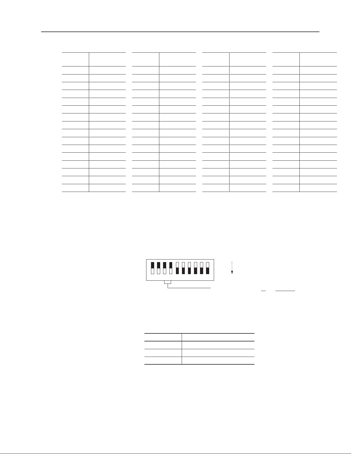
Setting the Data Rate
6 1
DIP switches 7 and 8 set the data rate at which the RediSTATION
communicates on the DeviceNet network. The factory default
setting is 125K BPS.
Default Configuration
OFF = 0
10 123456789
ON = 1
DeviceNet Data Rate 00 = 125K BPS
01 = 250K BPS
10 = 500K BPS
11 = Unused
The data rate determines the maximum length of the DeviceNet
cable.
Data Rate Cable Length (Maximum)
125K BPS 500 meters (1600 feet)
250K BPS 200 meters (600 feet)
500K BPS 100 meters (300 feet)
To set the DeviceNet data rate:
1. Refer to the table above to select the correct data rate.
2. Slide switches 7 and 8 to the appropriate ON/OFF positions.
Page 6

6
Setting the Output Fault State
DIP switch 9 sets the state of the outputs (pilot lights) when the
device detects an error. The factory default setting is to turn the
outputs off when an error is detected.
Default Configuration
OFF = 0
10 123456789
Output Fault State 0 = Outputs Turn Off on Fault
Output Fault States Description
Outputs Retain Last State
Outputs Turn Off on Error
ON = 1
1 = Outputs Hold Last State on Fault
When communications is lost, the station stops sending signals. The station ignores push button presses in the error
state. The outputs remain in their last state.
When communications is lost, the station turns off outputs. The
station ignores push button presses in the error state. When
communications is regained, the station updates itself and
resumes operations.
DeviceNet Termination
To change the fault state, slide switch 9 to the appropriate ON/OFF
setting.
Setting the Output Flash Rate
DIP switch 10 sets the flash rate of the outputs (pilot lights). The
factory default setting is 1 Hz.
Default Configuration
OFF = 0
10 123456789
Output Flash Rate 0 = 1 Hz (0.5 sec On, 0.5 sec Off)
To change the flash rate, slide switch 10 to the appropriate ON/OFF
position.
Devices on end nodes of the DeviceNet network require termination.
If the RediSTATION is an end node, you must provide network
termination.
To terminate the RediSTATION, install a 121 ohm 1% metal film
resistor between the CAN_High and CAN_Low terminals on the
DeviceNet terminal block.
ON = 1
1 = 2 Hz (0.25 sec On, 0.25 sec Off)
CAN_Low
DeviceNet Removable
Terminal Block
CAN_High
Page 7

Operations
7
Modes of Operation
The RediStation has 3 modes of operations:
• Powerup / Reset mode
• Run mode
• Error mode
Powerup/Reset Mode
During a powerup or reset, the RediSTATION:
1. Clears outputs (turns outputs off) and sets the LED indicator to
solid red.
2. Performs powerup diagnostic tests including:
– EPROM checksum test
– RAM read/write test
– Watchdog timer test
– Serial number verification
If any test fails, the outputs remain off and the LED remains solid
red. You must cycle power to recover from a power-up
diagnostic test failure. Repeated failures indicate a faulty unit.
3. Reads and stores the DIP switch settings.
Important: DIP switches are only read in powerup or reset
mode. Changes to DIP switch settings under power cause an
error.
4. Performs a duplicate node address check to verify that another
node is not assigned the same DeviceNet address as the
RediSTATION device.
If a duplicate node error occurs, the outputs turn off and the status
led is set to blinking red. You must cycle power to clear the error.
During a powerup or reset, the LED is red. If the powerup or reset is
successful, the RediSTATION enters run mode and the LED flashes
green.
Run Mode
After a successful powerup or reset, the RediSTATION enters run
mode and operates as a slave device to a master device. In run
mode, the:
• controller scans switch inputs and writes lamp outputs.
• station accepts output messages and poll messages from other
nodes on the DeviceNet network.
• station monitors outputs for underloads/overloads.
Page 8

8
Critical
le)
Solid Red
Non-Critical
le)
Flashing Red
If an output error is detected, the RediSTATION sets the appropriate
message bits and remains in run mode.
In run mode, you can configure the outputs to:
• turn on
• turn off
• flash
DIP switch 10 controls the rate of flashing for outputs.
The RediSTATION also supports DeviceNet configuration messages
that are received over the network.
Error Mode
In error mode (LED turns red), the RediSTATION monitors the error
state for correct operation. Errors are critical or noncritical.
Error Type Description LED State
Failure of diagnostic tests during powerup/reset mode
Over-temperature condition of outputs during runtime
(Not recoverab
(Recoverab
Changes to DIP switches during runtime
Duplicate node address detected
Incorrect data rate
Pilot lamp burned out – open circuit on output
Pilot lamp wired incorrectly – short circuit/overload
I/O connection timeout
Solid Red
Flashing Red
See the troubleshooting chart for details on how to recover from an
error.
Page 9

9
DeviceNet Operations
The Allen-Bradley 1747-SDN and 1771-SDN DeviceNet Scanner
Modules are master devices on the DeviceNet network. The
RediSTATION supports the Master/Slave Connection Set for
master/slave communications on the DeviceNet network.
To communicate with a RediSTATION, the DeviceNet Scanner
Module must be configured with the RediSTATION:
• node address
• input bytes (1)
• output bytes (1)
The DeviceNet Scanner Module:
• connects to the RediSTATION slave device
• performs the appropriate connection configuration
• polls the RediSTATION for inputs and outputs
Response Times
The RediSTATION responds to a DeviceNet Scanner poll within 1
millisecond.
The switch inputs are debounced for 50 milliseconds. When a
change of state is detected, the inputs are not read for another 50
milliseconds.
Page 10

10
Wh
Wh
Troubleshooting
Using the LED Indicator
The LED provides status information on RediSTATION operations.
The LED is visible when the enclosure cover is removed.
The troubleshooting chart shows LED indications. It also shows
how to use the LED to detect and correct common operating
problems.
LED
Color State
None 1. RediST ATION is not receiving input power. 1. Check DeviceNet power and cable
Red Solid 1. Diagnostics failed on powerup/reset.
at it Means:
2. DIP switch settings changed after powerup.
DIP Switch settings are only read during a
powerup/reset.
3. Over–temperature error detected during
runtime. Outputs turn off.
4. Invalid data rate.
1. Duplicate DeviceNet node address. Two
nodes cannot have the same address.
at to do:
connections and the power connection on the
DeviceNet terminal block. Page 3 references
this connection.
1. Internal fault. Reset device. If fault still
exists, return RediSTATION for repair.
2. Power down RediSTATION. Set DIP switch
settings. Reconnect power.
3. Check ambient temperature rating. Reset
device.
4. Reset DIP switches 7 and 8 to a valid
DeviceNet data rate. See page 5 for valid
data rates and cable lengths. Reset device.
1. Reset DIP switches 1 through 6 using a valid
address. Page 4 provides a table of
possible address settings. Reset device.
2. Pilot light lamp is burnt out – open circuit on
Red Flashing
Green Solid 1. Normal operating state and device is
Green Flashing 1. Device is online but not allocated to master.
output.
3. Pilot light is not wired correctly to the I/O
connector or the screw terminals of the
device – short circuit/overload.
4. I/O connection timeout.
allocated to a master device.
2. Device is in idle state.
The LED does not indicate the following malfunctions.
Problem What it Means: What to do:
Switch or button operators
do not function
1. Loose wiring
2. Incorrect address
3. Faulty contacts, switch or button
2. Replace pilot lamp bulb.
3. Check I/O cable connections for the pilot light
device.
4. Reset device.
1. No action required.
1. Check DeviceNet master for correct
RediST ATION configuration information (node
address, input bytes, output bytes).
2. Check DeviceNet master for proper
operation.
1. Check wiring and cable connections.
2. Check address setting of the DIP switch.
3. Use an ohmmeter to verify opening/closing of
contacts.
Page 11

User-Defined Configuration
An unpopulated configuration is available for customer
configuration and installation of operator devices. This section
provides information on:
• Kit Contents
• DeviceNet Interface Board Specifications
• Mounting Dimensions of Board
• Connecting Devices to Board
11
Kit Contents
The unpopulated configuration consists of:
• DeviceNet Interface Board
• Six I/O Connector Cables (supporting 4 inputs and 2 outputs)
• DeviceNet PCB Terminal Block
• Mounting Hardware
2 Circuit Board
Mounting Screws
Interface Board
I/O Connector
DeviceNet
Terminal Block
4 Circuit Board Spacers
(2 sizes provided)
Six I/O Connector Cables
Page 12

12
Specifications of DeviceNet Interface Board
Electrical
Supply Voltage 11 to 25 VDC
Power Consumption 7 Watts Maximum
Inputs
Maximum Number 4
Type Hard Contact Sourcing
Voltage/Current 24 VDC/24mA Maximum
Isolation None
Outputs
Maximum Number 2
Voltage/Current 24 VDC/100mA Maximum
Isolation None
Communications
DeviceNet
Baud Rates 125K, 250K, 500K
Distance Max. 500 meters (1600 feet) @125K
200 meters (600 feet) @250K
100 meters (300 feet) @500K
Environment
Ambient Temperature
Operating 0 to 55° C (32 to 131° F)
Storage -40 to 85° C (-40 to 185° F)
Relative Humidity (non-condensing) 5 to 95%
50% max at 40° C (104° F)
Page 13

13
Connecting Devices
This section shows how to connect devices to the DeviceNet
Interface Board and connect the DeviceNet cable to the DeviceNet
terminal block connector.
To install devices:
1. Connect the device terminals to the I/O connector using the I/O
cables. An I/O cable consists of a twisted (red/black) wire pair.
Each set of contacts or pilot light connects to an I/O cable.
I/O Connector
I/O Cable
to Device Terminals
Every 2 consecutive pins on the I/O connector connects to an I/O
cable connector. The I/O connector supports 2 outputs and 4
inputs.
I/O Connector
I/O Cable (Up to 6)
Circuit Board
ATTENTION: Do not connect I/O pins to standard control
voltages. See Page 12 for maximum voltages. I/O pins are
!
not electrically isolated from the DeviceNet circuitry.
To Output
To Output
To Input
To Input
To Input
To Input
Page 14

14
Connects O
e
Connects O
e
Connects In
e
Connects In
e
Connects In
e
Connects In
e
To simplify wiring, input devices and output devices attach to
opposite ends of the I/O connector. The following table defines
pin functions on the I/O connector. Output devices connect to
pins 1–2 and 3–4. Input devices connect to pins 5–6, 7–8, 9–10
and 11–12. Unused pins are left open.
I/O Connector Pin # Pin Label Function
1 OUT1+
2 OUT1–
3 OUT2+
4 OUT2–
5 IN4+
6 IN4–
7 IN3+
8 IN3–
9 IN2+
10 IN2–
11 IN1+
12 IN1–
utput Devic
utput Devic
put Devic
put Devic
put Devic
put Devic
2. Mount the circuit board using the spacers and mounting screws
provided. Tighten circuit board mounting screws to 14 in-lbs.
3. Attach the 6 DeviceNet cable leads to the DeviceNet removable
terminal block connector.
Page 3 provides a description of the DeviceNet connections.
Pin 1
Common
CAN Low
Shield
CAN High
VDC+
E GND
Pin 6
Removable Terminal
Block Connector
Page 15

Copyright 1999 Allen-Bradley Company, Inc. Printed in USA
41061-116-01(A)
 Loading...