

Page 1

Allen-Bradley
Bulletin 2705
RediPANEL
ALLEN–BRADLEY
User
Push Button
Modules
Manual
Page 2

Important User Information
Solid state equipment has operational characteristics differing from those of
electromechanical equipment. “Safety Guidelines for the Application,
Installation and Maintenance of Solid State Controls” (Publication SGI-1.1)
describes some important differences between solid state equipment and
hard–wired electromechanical devices. Because of this difference, and also
because of the wide variety of uses for solid state equipment, all persons
responsible for applying this equipment must satisfy themselves that each
intended application of this equipment is acceptable.
In no event will the Allen-Bradley Company be responsible or liable for
indirect or consequential damages resulting from the use or application of
this equipment.
The examples and diagrams in this manual are included solely for illustrative
purposes. Because of the many variables and requirements associated with
any particular installation, the Allen-Bradley Company cannot assume
responsibility or liability for actual use based on the examples and diagrams.
No patent liability is assumed by Allen-Bradley Company with respect to use
of information, circuits, equipment, or software described in this manual.
Reproduction of the contents of this manual, in whole or in part, without
written permission of the Allen-Bradley Company is prohibited.
Throughout this manual we use notes to make you aware of safety
considerations.
ATTENTION: Identifies information about practices or
circumstances that can lead to personal injury or death, property
!
damage, or economic loss.
Attentions help you:
• identify a hazard
• avoid the hazard
• recognize the consequences
Important: Identifies information that is especially important for successful
application and understanding of the product.
PLC, PLC–2, PLC–3, and PLC–5 are registered trademarks of Allen-Bradley Company, Inc.
SLC, SLC 500, PanelView, RediPANEL, and Dataliner are trademarks of Allen-Bradley Company, Inc.
IBM is a registered trademark of International Business Machines, Incorporated.
Page 3

Table of Contents
Bulletin 2705 RediPANEL Modules
User Manual
Preface
Contents of Manual P–1. . . . . . . . . . . . . . . . . . . . . . . . . . . . . . . . . . . . . . . .
Intended Audience P–2. . . . . . . . . . . . . . . . . . . . . . . . . . . . . . . . . . . . . . . . .
Related Publications P–2. . . . . . . . . . . . . . . . . . . . . . . . . . . . . . . . . . . . . . .
Overview
Configuring the RediPANEL Module
Wiring and Installation
Chapter 1
Chapter Objectives 1–1. . . . . . . . . . . . . . . . . . . . . . . . . . . . . . . . . . . . . . . . .
Description 1–1. . . . . . . . . . . . . . . . . . . . . . . . . . . . . . . . . . . . . . . . . . . . . . .
800A (16mm) Push Button Modules 1–2. . . . . . . . . . . . . . . . . . . . . . . . . . .
800EP/EM (22.5mm) Push Button Modules 1–2. . . . . . . . . . . . . . . . . . . . .
800T/H (30mm) Push Button Modules 1–4. . . . . . . . . . . . . . . . . . . . . . . . .
NEMA Type 4X Membrane Push Button Modules 1–5. . . . . . . . . . . . . . . .
Chapter 2
Chapter Objectives 2–1. . . . . . . . . . . . . . . . . . . . . . . . . . . . . . . . . . . . . . . . .
Calculating Rack Size 2–1. . . . . . . . . . . . . . . . . . . . . . . . . . . . . . . . . . . . . .
DIP Switches 2–3. . . . . . . . . . . . . . . . . . . . . . . . . . . . . . . . . . . . . . . . . . . . .
Setting Switch Bank 1 2–4. . . . . . . . . . . . . . . . . . . . . . . . . . . . . . . . . . . . . .
Setting Switch Bank 2 2–6. . . . . . . . . . . . . . . . . . . . . . . . . . . . . . . . . . . . . .
Input and Output Image Tables 2–8. . . . . . . . . . . . . . . . . . . . . . . . . . . . . . .
Chapter 3
Chapter Objectives 3–1. . . . . . . . . . . . . . . . . . . . . . . . . . . . . . . . . . . . . . . . .
Electrical Precautions 3–1. . . . . . . . . . . . . . . . . . . . . . . . . . . . . . . . . . . . . .
Grounding 3–1. . . . . . . . . . . . . . . . . . . . . . . . . . . . . . . . . . . . . . . . . . . . . . .
Power Requirements 3–2. . . . . . . . . . . . . . . . . . . . . . . . . . . . . . . . . . . . . . .
Connecting Power 3–2. . . . . . . . . . . . . . . . . . . . . . . . . . . . . . . . . . . . . . . . .
Enclosures 3–3. . . . . . . . . . . . . . . . . . . . . . . . . . . . . . . . . . . . . . . . . . . . . . .
Space and Clearance Requirements 3–4. . . . . . . . . . . . . . . . . . . . . . . . . . . .
Spacing of 800A Modules 3–4. . . . . . . . . . . . . . . . . . . . . . . . . . . . . . . .
Spacing of 800EM/EP Modules 3–5. . . . . . . . . . . . . . . . . . . . . . . . . . . .
Spacing of 800T/H Modules 3–7. . . . . . . . . . . . . . . . . . . . . . . . . . . . . .
Installing the 800A and Sealed Membrane Modules 3–8. . . . . . . . . . . . . . .
Installing the 800EM/EP Push Button Modules 3–10. . . . . . . . . . . . . . . . . .
800EM/EP Panel Mounting 3–10. . . . . . . . . . . . . . . . . . . . . . . . . . . . . . .
800EM/EP Fiberglass Enclosure Mounting 3–12. . . . . . . . . . . . . . . . . . .
800EM/EP Steel Enclosure Mounting 3–13. . . . . . . . . . . . . . . . . . . . . . .
Installing the 800T/H Push Button Modules 3–14. . . . . . . . . . . . . . . . . . . . .
Connecting to a Remote I/O Link 3–16. . . . . . . . . . . . . . . . . . . . . . . . . . . . .
Connecting to a Scanner Module 3–16. . . . . . . . . . . . . . . . . . . . . . . . . . . . . .
i
Page 4

Table of Contents
Bulletin 2705 RediPANEL Modules
User Manual
Programming the RediPANEL Module
Maintenance and Troubleshooting
Chapter 4
Chapter Objectives 4–1. . . . . . . . . . . . . . . . . . . . . . . . . . . . . . . . . . . . . . . . .
Module Bit Addresses 4–1. . . . . . . . . . . . . . . . . . . . . . . . . . . . . . . . . . . . . .
Bit Addresses for 8 Button Modules 4–1. . . . . . . . . . . . . . . . . . . . . . . .
Bit Addresses for 16 Button Modules 4–2. . . . . . . . . . . . . . . . . . . . . . .
Bit Addresses for 32 Button Modules 4–5. . . . . . . . . . . . . . . . . . . . . . .
Addressing Examples for 32 Button Modules 4–8. . . . . . . . . . . . . . . . .
Using a PLC-2 with a 1772-SD Scanner 4–9. . . . . . . . . . . . . . . . . . . . . . . .
Using a PLC-2 with a Sub I/O Scanner 4–11. . . . . . . . . . . . . . . . . . . . . . . . .
Using a PLC-5 4–14. . . . . . . . . . . . . . . . . . . . . . . . . . . . . . . . . . . . . . . . . . . .
Using a PLC-5 with a Sub I/O Scanner 4–15. . . . . . . . . . . . . . . . . . . . . . . . .
Operating Cycles 4–19. . . . . . . . . . . . . . . . . . . . . . . . . . . . . . . . . . . . . . . . . .
Response Time 4–20. . . . . . . . . . . . . . . . . . . . . . . . . . . . . . . . . . . . . . . . . . . .
Handshake Mode 4–21. . . . . . . . . . . . . . . . . . . . . . . . . . . . . . . . . . . . . . . . . .
PLC-5 – Flashing Lamp Example 4–23. . . . . . . . . . . . . . . . . . . . . . . . . . . . .
SLC 5/02 Programming Example 4–24. . . . . . . . . . . . . . . . . . . . . . . . . . . . .
Chapter 5
Chapter Objectives 5–1. . . . . . . . . . . . . . . . . . . . . . . . . . . . . . . . . . . . . . . . .
Preventive Maintenance 5–1. . . . . . . . . . . . . . . . . . . . . . . . . . . . . . . . . . . . .
Using the FAULT Indicator 5–2. . . . . . . . . . . . . . . . . . . . . . . . . . . . . . . . . .
Using the COMM Indicator 5–3. . . . . . . . . . . . . . . . . . . . . . . . . . . . . . . . . .
Using the Push-to-Test Button 5–4. . . . . . . . . . . . . . . . . . . . . . . . . . . . . . . .
Removing the Back Panel of RediPANEL 800T/H Modules 5–5. . . . . . . .
Basic Troubleshooting Questions 5–6. . . . . . . . . . . . . . . . . . . . . . . . . . . . .
Appendix A
Appendix B
Appendix C
Appendix D
Appendix E
Appendix F
Appendix G
Appendix H
ii
Specifications
Custom RediPANEL Modules
800A Switch Replacement Kit and LED Upgrade Kit
Adding/Replacing Push Button Legends
Replacing Lamps
Converting from Incandescent to LED Lamps
Installing/Replacing Push Buttons
Installing Color Inserts in Membrane Modules
Page 5

List of Figures
.
.
.
.
.
.
.
.
.6
.7
.9
.
.
.
.
.64.7
.94.
.
.A
.A2.B5.A
.B
Table of Contents
Bulletin 2705 RediPANEL Modules
User Manual
Figure
2
1
2
2
3
2
3
1
2
3
3
3
4
3
5
3
3
3
3.8
3
4.1
4
2
3
4
4
4
5
4
4
4.8
4
10
1
G
Title
!7,5&+ $0- !#9
$&- ''3(44 !(55,0*4 )13 9 7,5+ 9! !6% !&$00(3
DIP Switch Bank 1 (SW-1)
$&- ''3(44 !(55,0*4 )13 9 9 $0' ! 31&(44134
DIP Switch Bank 2 (SW-2) Settings
$0(. 65165 ,/(04,104 1) $0' !($.(' 1'6.(4
(25+ ,/(04,104 1) $0' !($.(' 1'6.(4
1605,0* 3$&-(5 "+6/%4&3(74
$0(. 65165 ,/(04,104 1) 64+ 65510 1'6.(4
(25+ ,/(04,104 1) 64+ 65510 1'6.(4
,%(3*.$44 0&.1463( 1605,0* ,/(04,104 1)
64+ 65510 1'6.(4
!5((. 0&.1463( 1605,0* ,/(04,104 1)
64+ 65510 1'6.(4
1605,0* ,/(04,104 1) 65510 " 1'6.(4
1605,0* ,/(04,104 1) 65510 " 1'6.(4
9 13 9 31*3$//,0* 8$/2.(
.1&- "3$04)(3 %(57((0 !6% !&$00(3 $0' 9
(/15( ''3(44,0* 7,5+ $ !6% !&$00(3
9 13 9 31*3$//,0* 8$/2.(
9 .1&- "3$04)(3
9 $0' !6% !&$00(3 31*3$//,0* 8$/2.(
9 $0' !6% !&$00(3 $''(3 1*,& 8$/2.(
$''(3 1*,& $0'4+$-( 60*
$0'4+$-( ",/,0* ,$*3$/4
.$4+,0* $ 65510 $/2
(2.$&,0* " 64+ 655104
Page
Table
1
2
5
List of Tables
Title
NEMA Ratings for 800EP/EM Devices 1–2. . . . . . . . . . . . . . . . . . . . . .
Rack Size Requirements for 8, 16 or 32 Button Modules 2–2. . . . . . . . .
DIP Switch Bank 2 (SW-2) Functions 2–7. . . . . . . . . . . . . . . . . . . . . . . .
Testing the Contacts of Illuminated Push Buttons 5–4. . . . . . . . . . . . . . .
Testing the Contacts of Illuminated Selector Switches 5–4. . . . . . . . . . .
Page
iii
Page 6

Preface
A–B
Preface
This manual gives an overview of the Bulletin 2705 RediPANEL Push
Button Modules and describes how to configure, install, program and
troubleshoot the device on the Allen-Bradley Remote I/O network.
Contents of Manual
This manual is organized as follows:
Chapter Title Description
Preface
1 Overview
2
3 Wiring and Installation
4
5
A Specifications Provides specifications for the RediPANEL modules.
B Custom RediPANEL Modules Describes how to create a custom unit.
C
D
E Replacing Lamps
F
G
H
Configuring the
RediPANEL Module
Programming the
RediPANEL Module
Troubleshooting
and Maintenance
800A Switch Replacement Kit
and LED Upgrade Kit
Adding/Replacing Push Button
Legends
Converting form Incandescent
Lamps to LED Lamps
Installing/Replacing
Push Buttons
Installing Color Inserts
in Membrane Modules
Describes the purpose and contents of the manual,
and the intended audience.
Provides an overview of the Bulletin 2705 RediPANEL
modules and the configurations available.
Describes how to configure RediPANEL functions
using the module’s DIP Switches. Configuration
includes the rack address, baud rate, handshaking,
flashing lamps, last state and fault mode behavior.
Describes how to install the RediPANEL module and
connect the module to a remote I/O link.
Describes how to program the RediPANEL module
from a PLC or SLC controller. Also covers handshake
mode and response times.
Describes how to troubleshoot and maintain the RediPANEL module.
Describes how to replace push buttons in the appropriate module. Also provides information for upgrading
from incandescent to LED lamps
Describes how to replace push button legends in Bulletin 800A Push Button Modules.
Describes how to replace lamps in Bulletin 800A Push
Button Modules.
Describes how to upgrade a Bulletin 800A Push Button Module from incandescent to LED lamps.
Describes how to replace push buttons in a RediPANEL module.
Describes how to install color legend inserts in Membrane type Modules.
P–1
Page 7

Preface
Intended Audience
Related Publications
This manual is for the individuals responsible for installing, mounting and
operating a RediPANEL Push Button Module in an industrial environment.
You must know how to program a PLC or SLC controller to operate the
RediPANEL module on a Remote I/O network. You must be able to:
• create a ladder logic program in your PLC or SLC controller
• understand basic PLC or SLC ladder logic addressing
• program block transfer instructions (when using Sub I/O Scanners)
Related publications you may want to refer to include:
• User manual and other support documentation for your processor and
scanner.
• Allen-Bradley Publication 1770-4.1 for grounding and wiring guidelines.
• National Electrical Code published by the National Fire Protection
Association of Boston, Massachusetts (refer to sections on wire sizes and
types for grounding electrical equipment).
P–2
Page 8

Chapter
Chapter Objectives
Description
A–B
1
Overview
This chapter describes the features, functions and operation of the Bulletin
2705 RediPANEL Push Button Modules.
Section Page
Description 1–1
800A (16mm) Push Button Modules 1–2
800EM/EP (22.5mm) Push Button Modules 1–2
800T/H (30mm) Push Button Modules 1–4
NEMA Type 4X Membrane Push Button Modules 1–5
The Bulletin 2705 RediPANEL Push Button Modules are prepackaged push
button stations that connect to Allen-Bradley programmable controllers over
a Remote I/O link.
RediPANEL Push Button Modules are available with:
• Bulletin 800A (16mm) devices
• Bulletin 800EP or 800EM (22.5mm) devices
• Bulletin 800T or 800H (30mm) devices
• Sealed membrane buttons for NEMA 4X (indoor) applications
Features of the RediPANEL Push Button Modules include:
• standard and custom configurations with 8, 16, or 32 push buttons
• remote I/O operations
• built-in diagnostics
• simultaneous push button applications
• handshake mode for data input integrity
• Diagnostic Indicators
1–1
Page 9

Chapter 1
Overview
800A (16mm) Push Button Modules
RediPANEL 800A Modules support Bulletin 800A push buttons in 2
configurations:
• standard
• custom
The 800A modules can operate in Class 1, Division 2, Groups A, B, C, and D
hazardous locations.
Standard Configuration
Standard configurations support 8, 16 or 32 momentary illuminated 800A
push buttons.
Custom Configuration
Custom configurations support any 8, 16 or 32 of the following 800A
devices:
• Momentary push buttons, illuminated
• Maintained push buttons, illuminated
• Flush head or extended head operators
• 2 position selector switches
• 2 position key switches
800EP/EM (22.5mm) Push Button Modules
1–2
RediPANEL 800EP/EM Modules support Bulletin 800EP and 800EM
22.5mm devices. Table 1.A lists NEMA ratings for 800EP/EM devices.
Table 1.A
NEMA IEC Ratings for 800EP/EM Devices
Type of Enclosure
Device
800EP 4/12/13, IP66 4/4X/12/13, IP66 12/13, IP65 4/4X/12/13, IP66
800EM 4/12/13, IP66 4/12/13, IP66 12/13, IP65 4/12/13, IP66
Cold Rolled Steel
Faceplate
Stainless Steel
Faceplate
Metal Enclosure
Fiberglass
Enclosure
RediPANEL 800EP/EM modules are available in 3 configurations:
• standard
• custom
• unpopulated
Standard Configuration
Standard configurations support 16 or 32 illuminated 800EP/EM push
buttons.
Page 10

Chapter 1
Overview
Custom Configuration
Custom configurations support any 16 or 32 of the following 800EP or
800EM devices:
• Momentary push buttons, illuminated/non-illuminated
• Maintained push buttons, illuminated/non-illuminated
• Flush head, extended head, or 40mm mushroom head operators
• Pilot lights
• 2 position selector switches, illuminated/non-illuminated
• 3 position selector switches, illuminated/non-illuminated
• Hole closing plugs
3 position devices use two RediPANEL inputs leaving an unused hole on the
front panel (hole plug 800E-N2).
Unpopulated Configuration
You can order an unpopulated 800EM/EP RediPANEL Module. The
unpopulated configuration consists of the enclosure and electronics without
the 800EM or 800EP devices. Each 800EM/EP device is ordered separately.
ATTENTION: Only install Allen-Bradley 800EM or 800EP
devices in the RediPANEL module. Using operators from other
!
manufacturers voids the warranty.
1–3
Page 11

Chapter 1
Overview
800T/H (30mm) Push Button Modules
RediPANEL 800T/800H Modules support Bulletin 800T and 800H 30mm
120 VAC, Class 1, Div. 2 Groups A, B, C, and D devices only. The 800T
devices have a NEMA Type 12/13 rating for applications requiring
protection from oil and dust. The stainless steel faceplate of 800H devices is
designed for NEMA Type 4, 4X applications (hosedown or corrosive
environments).
RediPANEL 800T/H modules are available in 3 configurations:
• standard
• custom
• unpopulated
Standard Configuration
Standard configurations support 16 or 32 illuminated 800T/H push buttons.
Custom Configuration
Custom configurations support any 16 or 32 of the following 800T or 800H
devices:
1–4
• Momentary push buttons, illuminated/non-illuminated
• Push/Pull push buttons, illuminated/non-illuminated
• Flush head, extended head or mushroom head operators
• Pilot lights
• 2 position selector switches, illuminated/non-illuminated
• 3 position selector switches, illuminated/non-illuminated
• 4 position selector switches
• Hole closing plugs
3 or 4 position devices use 2 RediPANEL inputs (and 2 connector cables),
leaving a physical location with an output bit only. You can either:
1. Reduce the total number of push button devices by one for each 3 or 4
position device. Use a hole plug (Catalog No. 800T-N1B) to cover the
unused hole.
For example, a 16 button module that includes a 3 or 4 position device
can have a maximum of 14 additional push buttons.
2. Use a pilot light adapter cable (Catalog 800T-N309) to install a 3 or 4
position pilot light instead of the hole plug.
The above example would then support an additional pilot light for a total
of 16 devices.
Page 12

Chapter 1
Overview
Unpopulated Configuration
You can order an unpopulated 800T/800H RediPANEL module. The
unpopulated configuration consists of the enclosure and electronics without
the 800T or 800H devices. Each 800H/T device is ordered separately.
ATTENTION: Only install Allen-Bradley 800T or 800H
devices in the RediPANEL. Using operators from other
!
manufacturers voids the warranty.
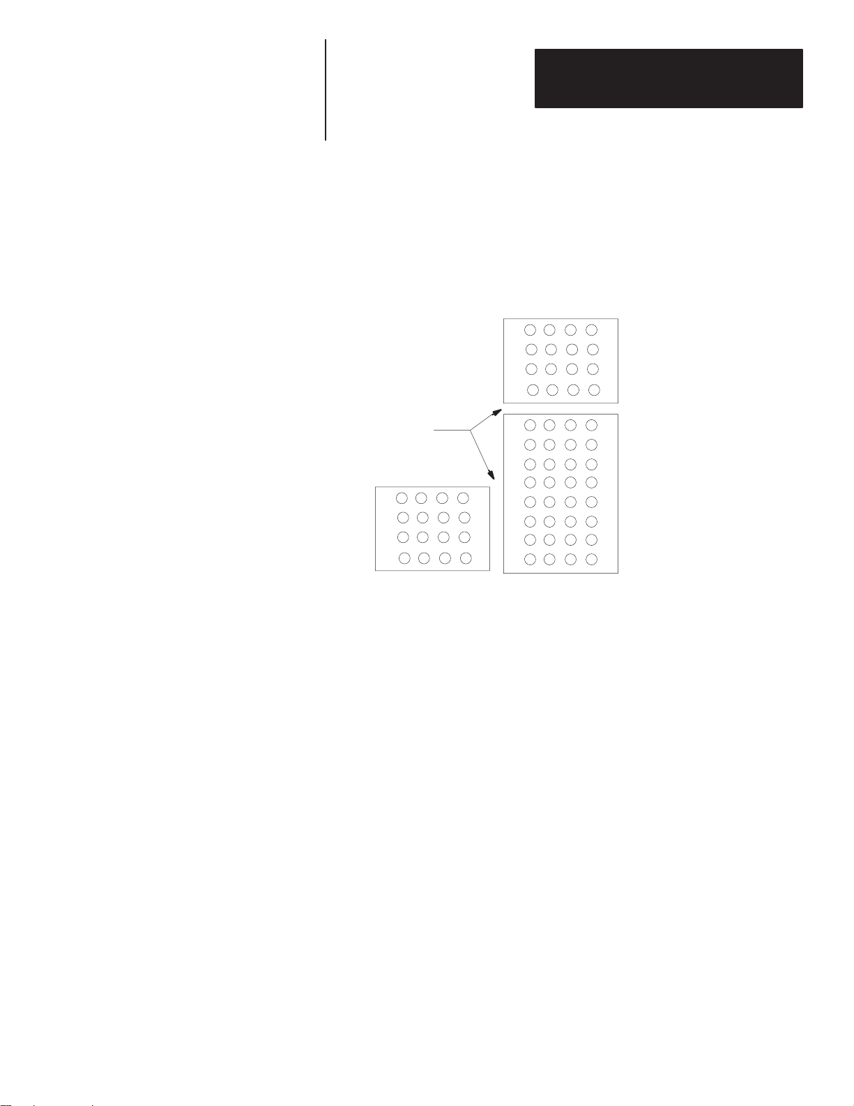
NEMA Type 4X Membrane Push Button Modules
The NEMA Type 4X Membrane Push Button Module has a standard
configuration of 4 rows of 4 buttons. Each button has an LED in the upper
right corner. These LEDs perform the same function as the lamp on the
standard push button modules.
The module comes with five different color inserts to legend each button
location. The inserts are coated mylar stock for writing (ink, pencil, or
marker), typing, or printing a legend.
1–5
Page 13

Chapter
Chapter Objectives
Calculating Rack Size
A–B
2
Configuring the RediPANEL Module
This shows how to configure the RediPANEL Module using DIP Switches.
Section Page
Calculating Rack Size 2–1
DIP Switches 2–3
Setting Switch Bank 1 2–4
Setting Switch Bank 2 2–6
Input and Output Image Tables 2–8
DIP Switches on the RediPANEL are used to set Input/Output (I/O)
requirements. On a Remote I/O network, I/O is measured in terms of racks.
The smallest unit is a 1/4 rack.
Rack size determines the amount of space the module uses in the Input and
Output Image tables. When you select a rack size (using DIP switches),
space is reserved in the Input and Output Image Tables of your processor.
Three factors determine rack size:
• Input/Output size
• Flashing functions
• Handshaking functions
Input/Output Size
Input/Output Size directly relates to the number of push buttons on the
RediPANEL module. A 16 push button module has 16 inputs and 16
outputs. A 32 push button module has 32 inputs and 32 outputs.
Flashing Function
The flashing function causes the RediPANEL outputs to flash without
additional PLC programming. If flashing is enabled, the processor allocates
additional memory in the I/O Image Table. By branching the RediPANEL
output bits with the corresponding flashing bits, the RediPANEL outputs
blink at a 0.5 second rate.
A 16 push button module requires 16 additional outputs. A 32 push button
module requires 32 additional outputs to enable the flashing function.
Handshake
The handshake function latches an input bit until it is acknowledged by the
processor. Handshaking requires an additional output bit in the Output
Image Table.
2–1
Page 14

Chapter 2
Lighted
Num er
Lighted
Lighted
1/4
1
1
3
Configuring the RediPANEL Module
Table 2.A lists the rack size requirements for an 8, 16 or 32 button
RediPANEL module. The rack size varies depending on the number of push
buttons and the functions used.
Table 2.A
Rack Size Requirements for 8, 16, and 32 Button RediPANEL Modules
Number
of Buttons
8
16
32
Handshake
No Yes
and Flashing
1/2 3/4
/2
You can ignore the I/O requirements in the table and specify a full rack by
setting switch 6 in DIP Switch Bank 2 on the RediPANEL. A full rack is
automatically reserved in the Input/Output Image Tables of the processor.
2–2
Page 15
Chapter 2
Configuring the RediPANEL Module
DIP Switches
DIP Switches
The RediPANEL module has two DIP Switch banks.
Switch Bank Function
Switch Bank 1 (SW-1) Sets rack address.
Switch Bank 2 (SW-2) Controls baud rate, flashing lamps, fault mode
behavior, handshaking and last states.
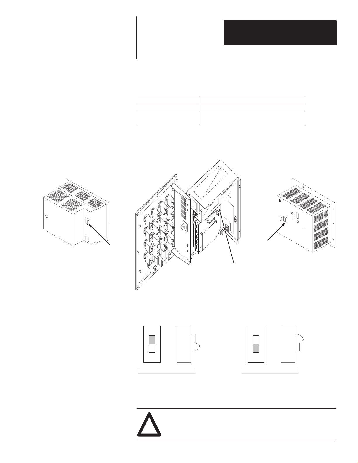
The DIP Switch banks are located on the back of the RediPANEL module.
You can access the DIP switches by opening the back panel, as shown below.
DIP Switches
800A Push Button Module
800T/H Module
DIP Switches
800EM/EP Module
(Steel enclosure mounting shown.
Other styles similar)
The following figure shows ON/OFF positions of the rocker style switches.
ON
OFF
FRONT SIDE
ON
ON and OFF switch settings are indicated by shading.
ON
OFF
FRONT SIDE
OFF
ATTENTION: Remove power from the module before setting
switches. Switch settings are scanned only on power-up.
!
The new settings take effect when you power-up the module.
2–3
Page 16
Chapter 2
Configuring the RediPANEL Module
Setting Switch Bank 1
OFF
ON
SW-1
Example
SW-1
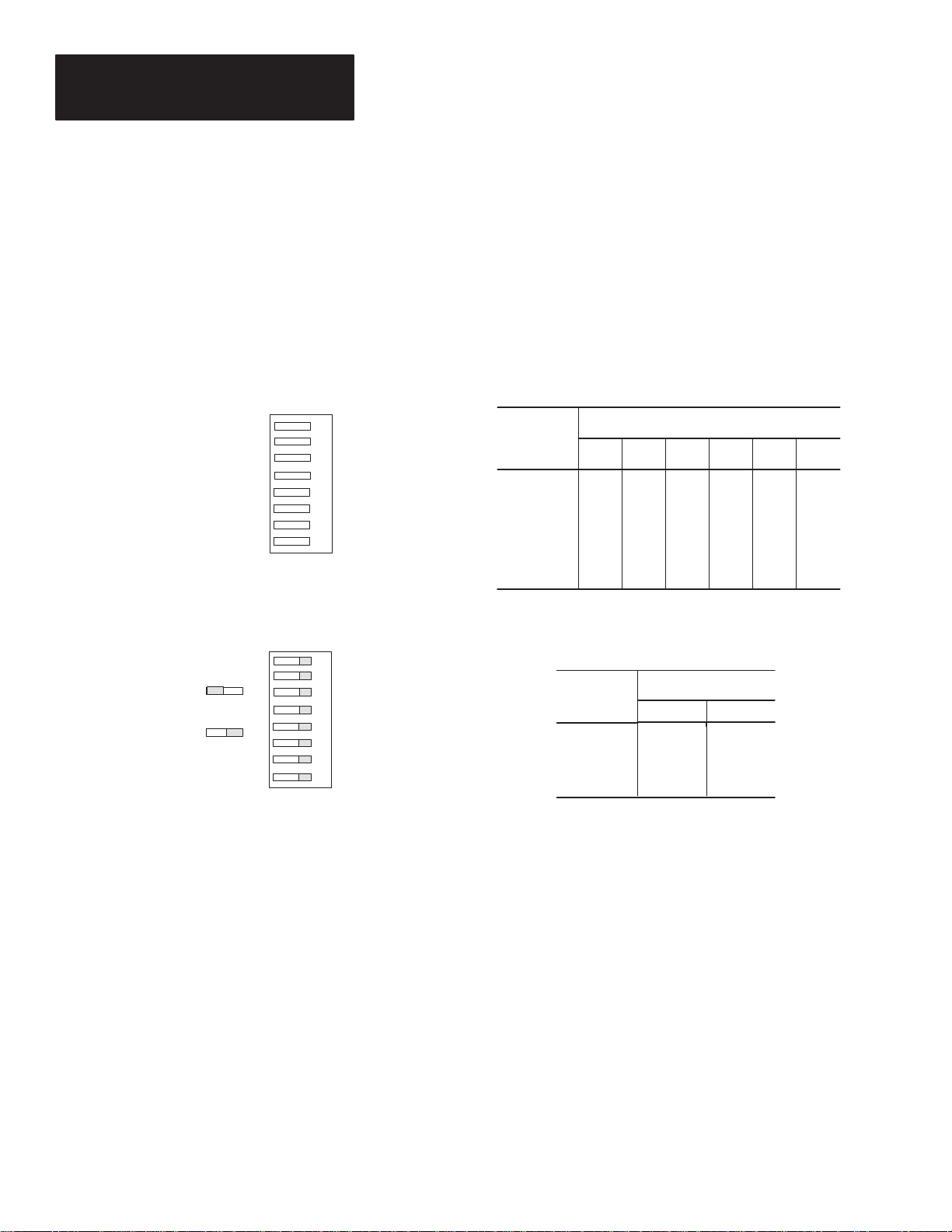
Switch Bank 1 (SW-1) sets the rack address.
Figure 2.1 shows rack address settings for the PLC-2 or any PLC using a
1771-SN Sub Scanner.
Figure 2.1
DIP Switch Bank 1
Rack Address Settings for PLC-2 or PLC with 1771-SN Sub Scanner
ONOFF
Rack address, MSB
1
Rack address
2
Rack address
3
Rack address
4
Rack address
5
Rack address, LSB
6
First I/O group, MSB
7
First I/O group, LSB
8
ONOFF
1
PLC-2
2
I/O rack
3
number 1
4
5
6
7
First I/0
8
group 0
Rack Address Settings for PLC-2 and 1771-SN Scanner
I/O Rack
Address
1
2
3
4
5
6
7
First I/O
Group
Switch Settings – Series B
on
on
on
on
on
on
on
on
on
Specifying First I/O Group
on
on
on
on
on
on
on
on
on
on
on
on
Switch Settings
78
0
2
4
6
on
on
off
off
on
on
on
on
off
off
off
on
on
off
off
on
on
off
on
off
on
off
653421
on
off
on
off
on
off
on
2–4
Figure 2.2 lists rack address settings for the PLC-3 and PLC-5 family.
Page 17
Chapter 2
I/O Rack
I/O Rack
I/O Rack
I/O Rack
rst I/O
rst I/O
Configuring the RediPANEL Module
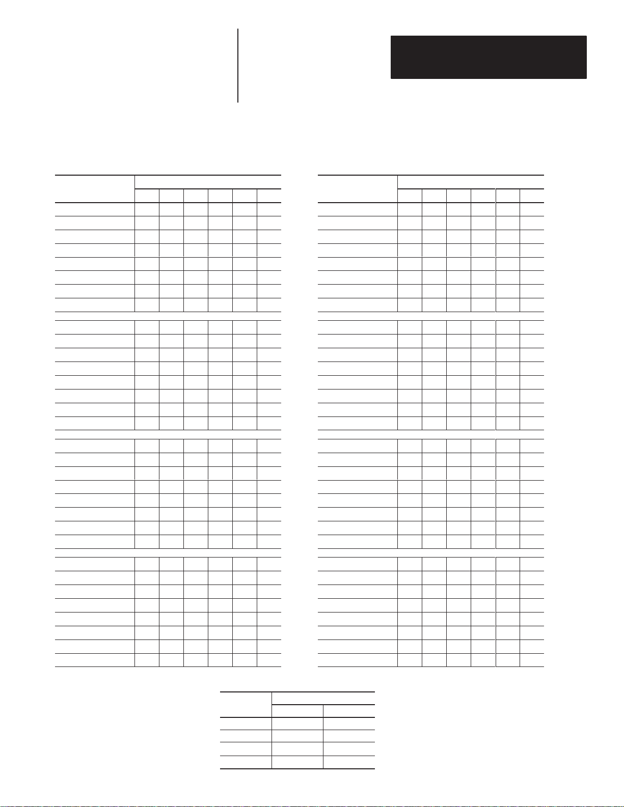
Figure 2.2
DIP Switch Bank 1
Rack Address Settings for PLC-3, PLC-5 and SLC Processors
Address
00 ➀
01 on on on on on off 41 off on on on on off
02 on on on on off on 42 off on on on off on
03 on on on on off off 43 off on on on off off
04 on on on off on on 44 off on on off on on
05 on on on off on off 45 off on on off on off
06 on on on off off on 46 off on on off off on
07 on on on off off off 47 off on on off off off
10 on on off on on on 50 off on off on on on
11 on on off on on off 51 off on off on on off
12 on on off on off on 52 off on off on off on
13 on on off on off off 53 off on off on off off
14 on on off off on on 54 off on off off on on
15 on on off off on off 55 off on off off on off
16 on on off off off on 56 off on off off off on
17 on on off off off off 57 off on off off off off
20 on off on on on on 60 off off on on on on
21 on off on on on off 61 off off on on on off
22 on off on on off on 62 off off on on off on
23 on off on on off off 63 off off on on off off
24 on off on off on on 64 off off on off on on
25 on off on off on off 65 off off on off on off
26 on off on off off on 66 off off on off off on
27 on off on off off off 67 off off on off off off
1
on on on on on on 40 off on on on on on
Switch Settings
2 3 4 5 6
Address
1
Switch Settings
2 3 4 5 6
30 on off off on on on 70 off off off on on on
31 on off off on on off 71 off off off on on off
32 on off off on off on 72 off off off on off on
33 on off off on off off 73 off off off on off off
34 on off off off on on 74 off off off off on on
35 on off off off on off 75 off off off off on off
36 on off off off off on 76 off off off off off on
37 on off off off off off
➀ Rack 00 not valid with PLC-5s.
Specifying First I/O Group
Fi
Fi
Group
0 on on
2 on off
4 off on
6 off off
Switch Settings
7
8
2–5
Page 18
Chapter 2
Configuring the RediPANEL Module
Setting Switch Bank 2
ONOFF
Baud Rate
1
2
Baud Rate
3
Flashing Lamps ENABLED
4
Switch Fault Mode
Last Rack
5
Rack Size
6
7
Handshake ENABLED
8
Last State ENABLED
SW-2
ONOFF
1
OFF
ON
SW-2
Baud Rate
2
Baud Rate
3
Flashing Lamps (DISABLED)
4
Switch Fault (HALT)
5
Last Chassis (NOT LAST)
6
Rack Size (TABLE)
7
Handshake (DISABLED)
8
Last State (DISABLED)
Example
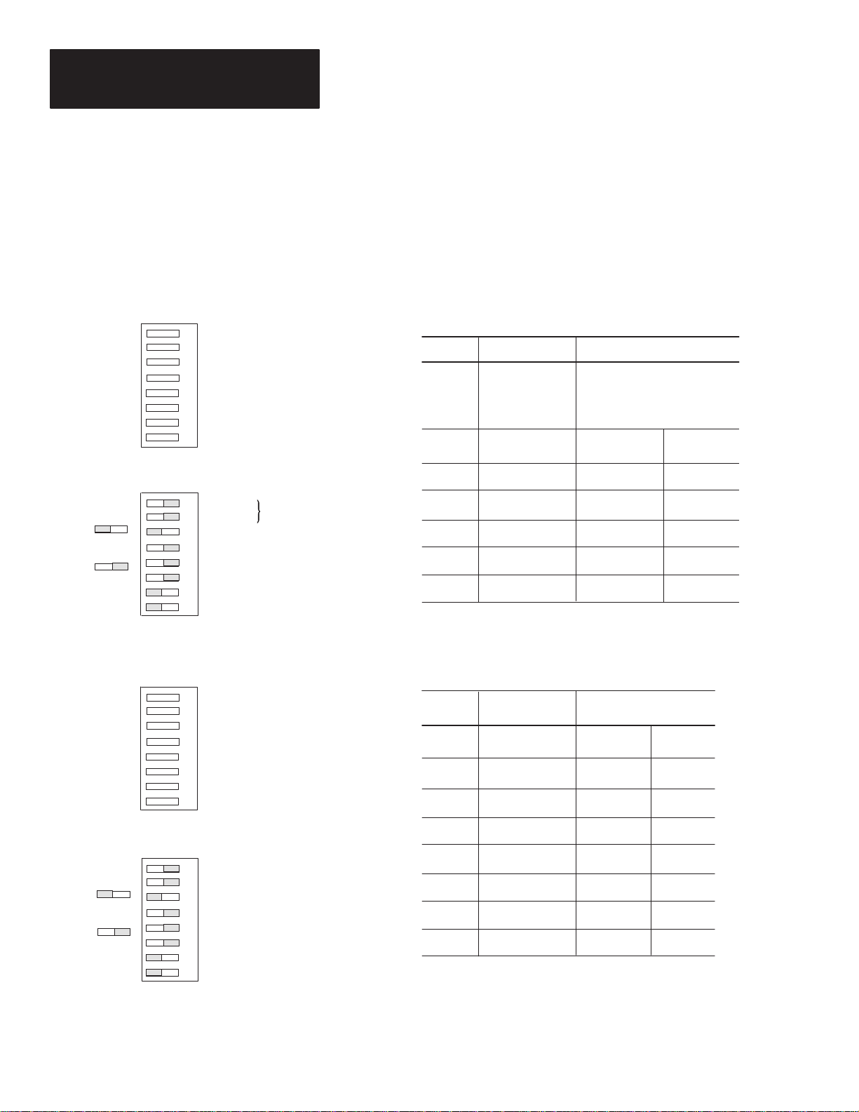
Figure 2.3 shows the functions and settings for Switch Bank 2 (SW-2).
Table 2.B defines the DIP Switch functions.
Figure 2.3
DIP Switch Bank 2 (SW-2) Settings
RediPANEL 800A and 800EP/EM Membrane Modules
Switch Description Switch Setting
(57.6K)
1 & 2 Baud Rate 57.K 1=ON 2=ON
3 Flashing Lamps OFF=Disabled ON=Enabled
4 Switch Fault OFF=Continue ON=Halt
5 Last Chassis OFF=Last ON=Not Last
6 Rack Size OFF=Full ON=Table
7 Handshake OFF=Disabled ON=Enabled
8 Last State OFF=Disabled ON=Enabled
115.2K 1=OFF 2=ON
230.4K 1=ON 2=OFF
N/A 1=OFF 2=OFF
OFF
ON
SW-2
SW–2
ONOFF
Baud Rate
1
2
Steady Lamps ENABLED
3
Flashing Lamps ENABLED
Switch Fault
4
Last Chassis
5
Rack Size
6
7
Handshake ENABLED
8
Last State ENABLED
ONOFF
Example
1
Baud Rate (57.6K)
2
Steady Lamps (ENABLED)
3
Flashing Lamps (DISABLED)
4
Switch Fault (HALT)
5
Last Chassis (NOT LAST)
6
Rack Size (TABLE)
7
Handshake (DISABLED)
8
Last State (DISABLED)
RediPANEL 800T/H Modules
Switch Description Switch Setting
OFF ON
1 Baud Rate 115.2K 57.6K
2 Steady Lamps Disabled Enabled
3 Flashing Lamps Disabled Enabled
4 Switch Fault Continue Halt
5 Last Chassis Last Not Last
6 Rack Size Full Table
7 Handshake Disabled Enabled
8 Last State Disabled Enabled
2–6
Page 19

Chapter 2
Options
Description
Configuring the RediPANEL Module
Table 2.B
DIP Switch Bank 2 (SW-2) Functions
DIP Switch SW2
Number Function
1, 2 ➀➁
3 Flashing Lamps
4 Switch Fault Mode
5 Last Rack
6 Rack Size
7 Handshake
8 Last State
➀ Switches 1 and 2 set the baud rate on RediPANEL 800A, 800EM/EP, and Membrane modules. Switch 1 only sets the baud rate on RediPANEL 800T/H
modules.
➁ Switch 2 sets steady lamps for the 800T/H RediPANEL.
Baud Rate
• 57.6K
• 115.2K
• 230.4K
• Enabled
• Disabled
• Halt
• Continue
• Last
• Not Last
• Full
• Table
• Enabled
• Disabled
• Enabled
• Disabled
• 57.6K for links up to 10,000 feet (3,000 meters)
• 115.2K for links up to 5,000 feet (1,500 meters)
• 230.4K for links up to 2,500 feet (750 meters)
When enabled, the Module uses the built-in flash feature to flash the lamps inside the
push button at a 0.5 sec. rate. Programming ON/OFF Timers is not necessary,
• Halt stops all push button operations when a fault is detected using the Push-to-Test
button. Communications with the PLC is disabled, the COMM LED turns off, and the
FAULT LED illuminates.
• Continue forces all associated input image table bits to the released state. The rest of
the push buttons continue to operate while the faulted button remains inoperable.
• Last tells the controller that the RediPANEL module is the last device in that logical rack,
not necessarily the last remote rack on the I/O link.
The Last setting is not a terminator resistor for the remote I/O link.
• Not Last specifies that the RediPANEL module is not the last device in the logical rack.
• Full configures the module as a full rack (regardless of the I/O requirements in Table
2.A).
The Full setting is required when connecting RediPANEL modules directly to
PLC-5/15 (Series B Revision G or earlier) or PLC-5/25 (Series A Revision C
or earlier) controllers.
• Table configures the rack size of the module using Table 2.A.
• When enabled, handshaking allows the use of the handshake bit. Any push button
depression is held ON until the controller verifies that it has received the signal.
The controller’s ladder logic must contain a handshake rung or the
RediPANEL module will not function properly.
See page 4–21 for details on using the Handshake Mode.
• When disabled, handshaking holds any push button depression ON for 100
milliseconds.
• If Last State is enabled, when communications is lost, the module stops sending signals
and the COMM LED turns off. Any output signals that were on when communication
was lost return to that state when communications is regained. The module locks up
and ignores any push button depressions. Lamps remain in their last state.
• If Last State is disabled, the module turns off any lamps that were on when
communications is lost. When communications is regained, the module updates itself
and resumes operations.
2–7
Page 20
Chapter 2
Configuring the RediPANEL Module
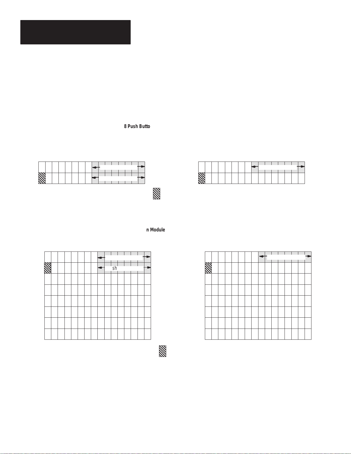
Input and Output Image Tables
Output Image Table - 1/4 Rack
(Handshaking , Lamps and Flash Enabled)
Output Image Table
This section shows the Input and Output Image Tables for 8, 16 and 32
button RediPANEL modules.
I/O Image Tables for 8 Push Button Modules
8 Push Button Module 1/4 Rack
Flash Control Bits
8 Push Button Module Set to Full Rack
012345671011121314151617 012345671011121314151617
WORD 0
WORD 1
Handshake Bit
Input Image Table - 1/4 Rack
(Handshaking Enabled)
Switch Status BitsLamp Control Bits
Input Image Table
Lamp Control Bits
Flash Control Bits
WORD 0
WORD 1
WORD 2
WORD 3
WORD 4
WORD 5
WORD 6
WORD 7
Handshake Bit
012345671011121314151617012345671011121314151617
Switch Status Bits
2–8
Page 21
Output Image Table
Î
Î
1
Rack (Lamps Enabled)
/4
Chapter 2
Configuring the RediPANEL Module
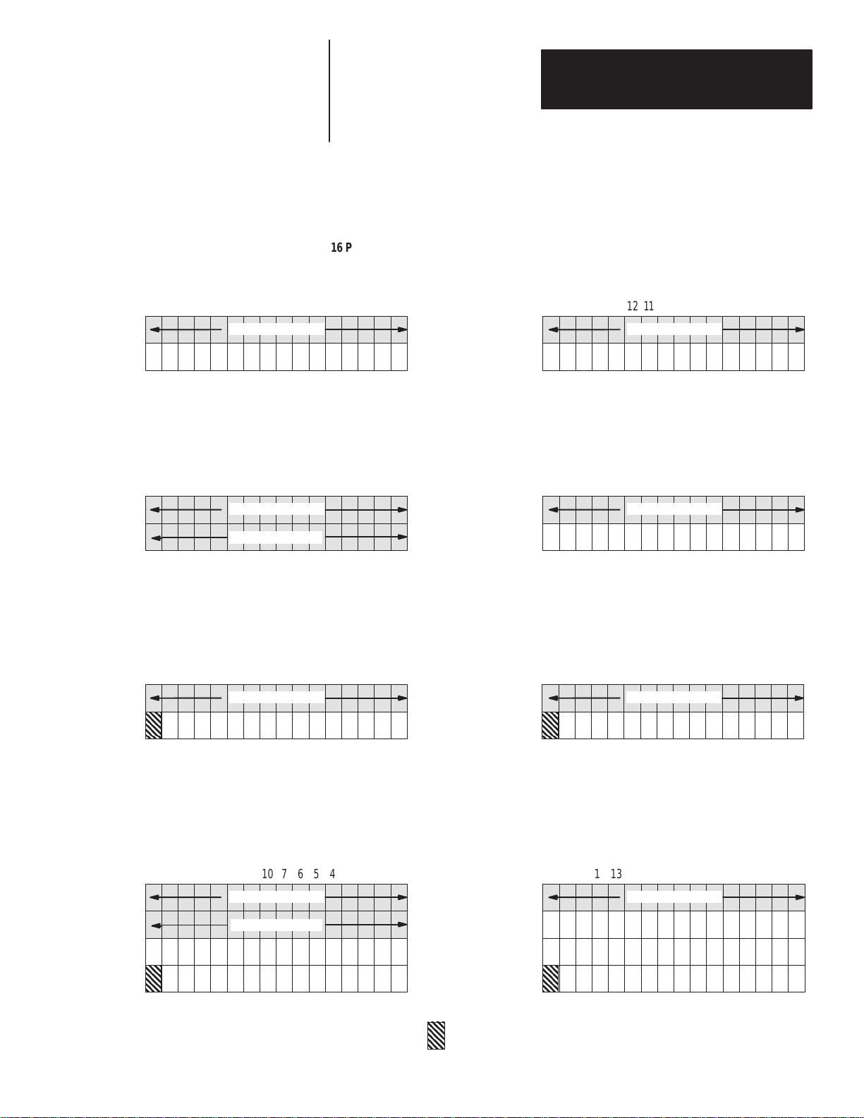
I/O Image Tables for 16 Push Button Modules
16 Push Button Module, 1/4 and 1/2 Rack
Input Image Table
1
/4 Rack
Lamp Control Bits
Output Image Table
1
/
Rack (Lamps & Flash Enabled)
4
Lamp Control Bits
Flash Control Bits
Output Image Table
1
/4 Rack (Handshaking & Lamps Enabled)
Lamp Control Bits
012345671011121314151617
WORD 0
Switch Status Bits
012345671011121314151617
WORD 1
Input Image Table
1
/4 Rack
012345671011121314151617
WORD 0
Switch Status Bits
012345671011121314151617
WORD 1
Input Image Table
1
/
Rack
4
012345671011121314151617
WORD 0
Switch Status Bits
012345671011121314151617
Output Image Table
1
/2 Rack (Handshaking, Lamps & Flash Enabled)
Lamp Control Bits
Flash Control Bits
WORD 1
Input Image Table
1
/
Rack (Handshaking Enabled)
4
012345671011121314151617
WORD 0
Switch Status Bits
012345671011121314151617
WORD 1
WORD 2
WORD 3
Handshake Bit
2–9
Page 22
Chapter 2
Configuring the RediPANEL Module
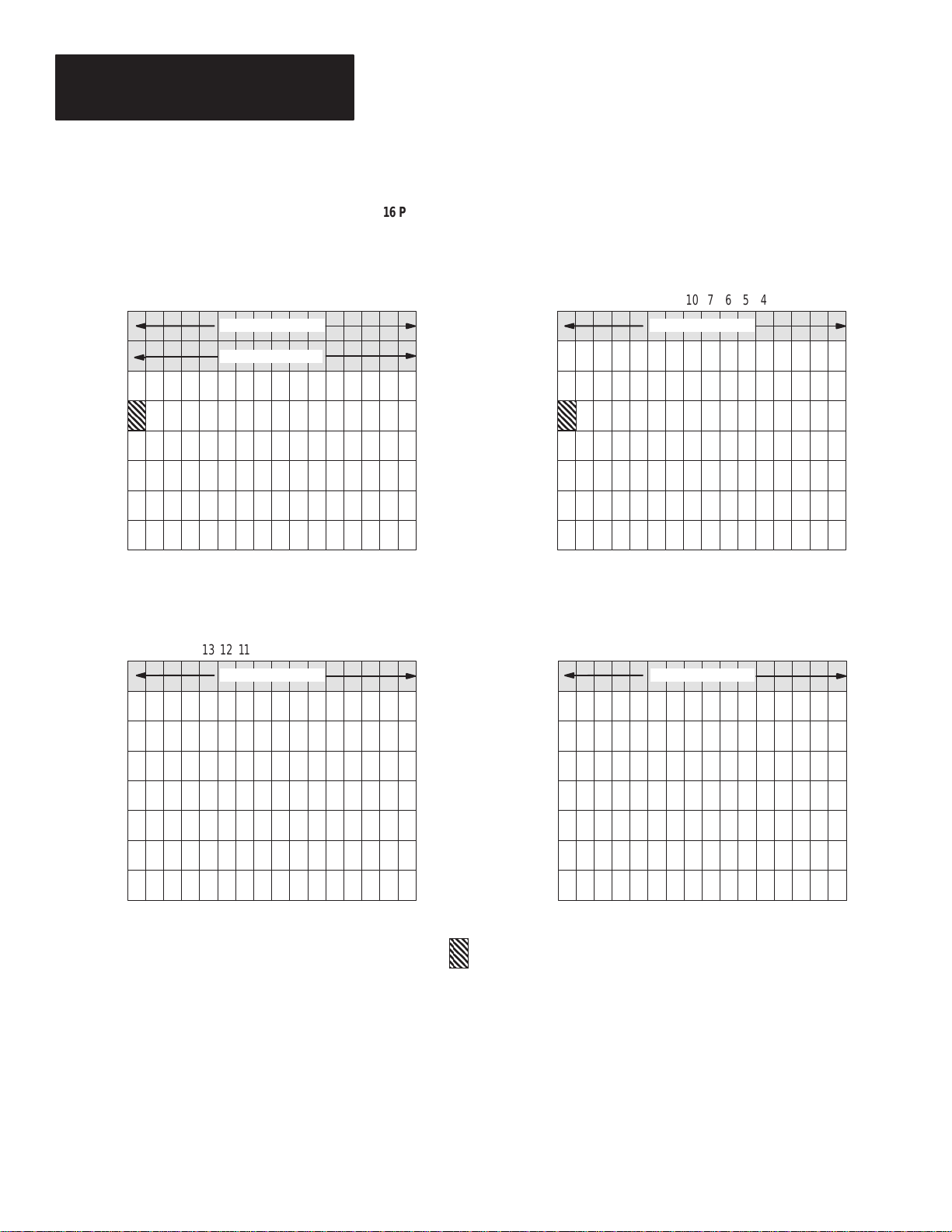
16 Push Button Module, Full Rack
Output Image Table
Full Rack (Lamps, Flash and Handshaking Enabled)
Lamp Control Bits
Flash Control Bits
Output Image Table
Full Rack (Lamps Enabled)
Lamp Control Bits
Input Image Table
Full Rack (Handshaking Enabled)
012345671011121314151617
WORD 0
WORD 1
WORD 2
WORD 3
WORD 4
WORD 5
WORD 6
WORD 7
Input Image Table
Full Rack
012345671011121314151617
WORD 0
Switch Status Bits
Switch Status Bits
012345671011121314151617
012345671011121314151617
WORD 1
WORD 2
WORD 3
WORD 4
WORD 5
WORD 6
WORD 7
Handshake Bit
Note: In 800T/H Push Button Modules, the cables that connect to the push buttons are marked A00- A17.
This corresponds to input and output bit locations 00-17.
2–10
Page 23
Chapter 2
Configuring the RediPANEL Module
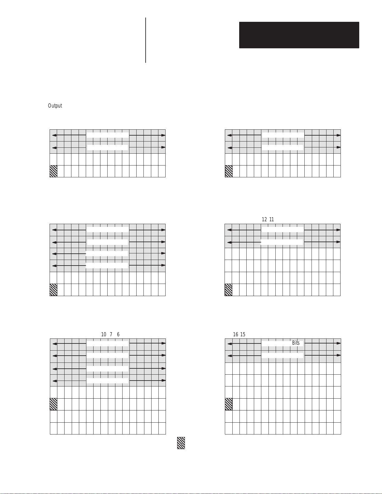
I/O Image Tables for 32 Push Button Modules
Output Image Table
1
/2 Rack (Handshaking and Lamps Enabled, Flash Disabled)
012345671011121314151617
Lamp Control Bits
Lamp Control Bits
Output Image Table
3
/4 Rack (Lamps, Flash and Handshaking Enabled)
012345671011121314151617
Lamp Control Bits
Lamp Control Bits
Flash Control Bits
Flash Control Bits
WORD 0
WORD 1
WORD 2
WORD 3
WORD 0
WORD 1
WORD 2
WORD 3
WORD 4
Input Image Table
1
/2 Rack (Handshaking Enabled)
Switch Status Bits
Switch Status Bits
Input Image Table
3
/4 Rack (Handshaking Enabled)
Switch Status Bits
Switch Status Bits
012345671011121314151617
012345671011121314151617
WORD 5
Output Image Table
Full Rack (Regardless of Configuration)
Input Image Table
Full Rack (Regardless of Configuration)
012345671011121314151617
Lamp Control Bits
Lamp Control Bits
Flash Control Bits
Flash Control Bits
WORD 0
WORD 1
WORD 2
WORD 3
WORD 4
WORD 5
WORD 6
WORD 7
Handshake Bit
Note: In 800T/H Push Button Modules, the cables that connect to the push buttons are marked A00- A17.
This corresponds to input and output bit locations 00-17.
012345671011121314151617
Switch Status Bits
Switch Status Bits
2–11
Page 24

Chapter
Chapter Objectives
A–B
3
Wiring and Installation
This chapter contains the following sections.
Section Page
Electrical Precautions 3–1
Grounding 3–1
Power Requirements 3–2
Connecting Power 3–2
Enclosures 3–3
Space and Clearance Requirements 3–4
Installing the 800A and Sealed Membrane Modules 3–8
Installing the 800EM/EP Modules 3–10
Installing the 800T/H Push Button Modules 3–14
Connecting to a Remote I/O Link 3–16
Connecting to a Scanner Module 3–16
Electrical Precautions
Grounding
Install the Bulletin 2705 Push Button Module using publication NFPA 70E,
Electrical Safety Requirements for Employee Workplaces.
ATTENTION: Do not program any of the devices on the Push
Button Module as emergency stop switches. Emergency stop
!
switches must be hardwired to the master control relay of the
system to turn off all machine power completely.
Additional guidelines to follow include:
• Careful wire routing helps cut down on electrical noise. Route incoming
power to the module by a separate path from the communication cables.
Do not run communications wiring and power wiring in the same
conduit!
• Where wire paths must cross, make their intersection perpendicular.
• Grounding helps to limit the effects of noise due to electromagnetic
interference (EMI). To avoid EMI, use shielded cables.
Grounding is an important safety measure in electrical installations. As
mentioned previously, with solid state systems grounding helps to limit the
effect of noise from EMI (electromagnetic interference).
An authoritative source on grounding requirements is the National Electrical
Code published by the National Fire Protection Association of Boston,
Massachusetts. Refer to an article of the Code that discusses the types and
sizes of wire conductors and safe methods of grounding electrical equipment
and components.
3–1
Page 25
Chapter 3
Wiring and Installation
Power Requirements
Connecting Power
RediPANEL Modules operate with different power sources.
Module Type Power Source
800A
Sealed Membrane
800T/H 120 or 240V AC, 47 - 63 Hz
800EM/EP
90 to 264V AC, 47 - 63 Hz
18 to 30V DC
90 to 264V AC, 47 - 63 Hz
18 to 30V DC
90 to 264V AC, 47 - 63 Hz
18 to 30V DC
The AC power supplies for the 800A and Membrane Modules have an
automatic over voltage shutdown. Automatic shutdown occurs if the output
voltage of the 5V supply rises by 25% or the 12V supply rises by 20%. To
reset the RediPANEL after an automatic shutdown, disconnect AC power as
follows:
For : Disconnect a AC power for:
120V AC Source minimum of 30 seconds
240V AC Source minimum of 60 seconds
Connect power lines to the module as shown below:
Terminal Block Connection
GND Ground Wire
L2/N Neutral Wire
L1 Power Wire
(–) DC 0 Volts
(+) DC +24 Volts
ATTENTION: Do not apply power to the module until all
electrical connections, including communications lines, have
!
been connected.
ATTENTION: The ground terminal (GND) must be connected
to a reliable low impedance earth ground to protect the display
!
against electrical noise. The ground will also help protect
personnel from electrical shock if a voltage is shorted to the
enclosure.
1. Connect ground wire to the GND terminal on the terminal block.
2. Connect the power lines, L1 and L2/N , or (–) and (+DC). Do not apply
power until all connections have been made.
3–2
3. Connect the communications lines as described on page 3-16.
4. Apply power and verify power up operation.
Page 26

Chapter 3
Wiring and Installation
Enclosures
You must use an enclosure to protect the electronics of the Push Button
Module from atmospheric contamination. Standards established by the
National Electrical Manufacturer’s Association (NEMA) define enclosure
types based on the degree of protection an enclosure will provide.
Heat Dissipation
Within the enclosure, the Push Button Module (or Modules) requires room
for convection cooling.
In some applications, other equipment inside (or outside) the enclosure may
produce too much heat. Place blower fans inside the enclosure to circulate
air to reduce hot spots near components. In extreme cases, use air
conditioning to prevent heat build-up.
ATTENTION: Do not use unfiltered outside air. It could
contain contaminants or dirt harmful to the components.
!
3–3
Page 27
Chapter 3
Wiring and Installation
Space and
Clearance Requirements
Spacing of 800A Modules
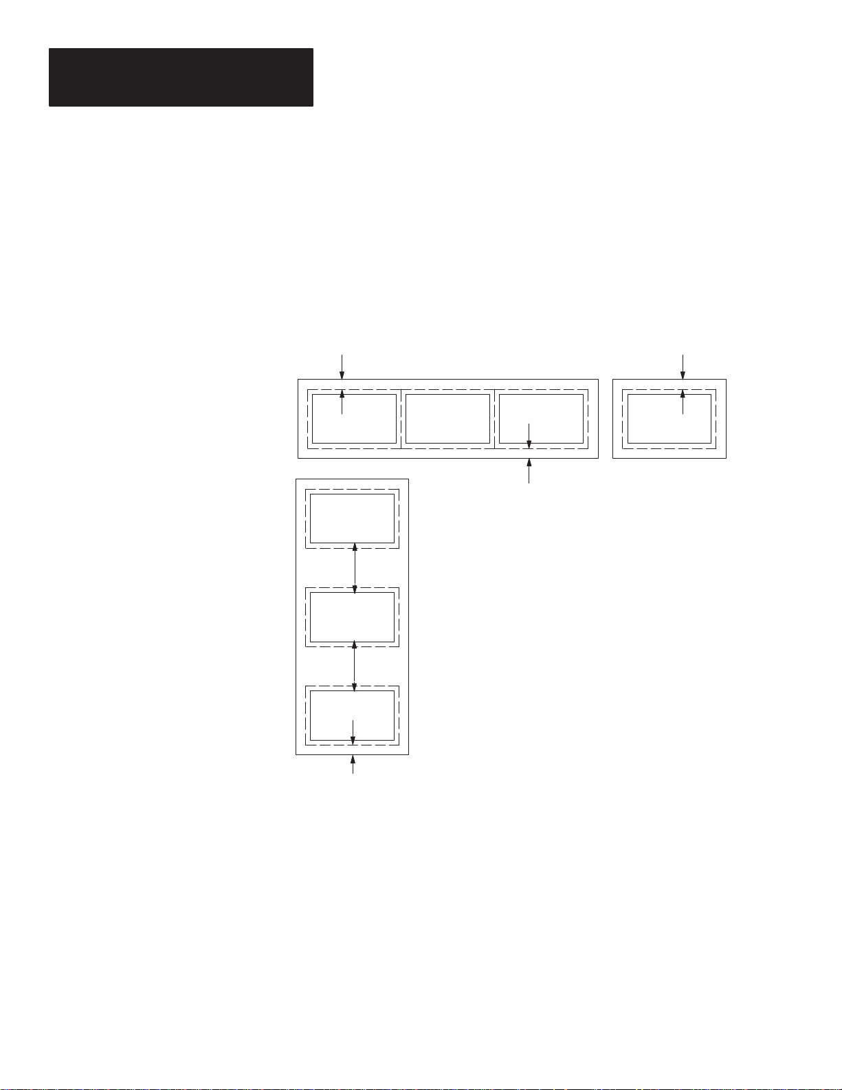
To properly space 800A Push Button Modules, follow these guidelines.
• Vertical stacking of modules: The lower edge of the top cutout must be
at least 6 inches (152mm) from the top edge of the lower cutout. The
enclosure must be at least 8 inches (203mm) deep.
• Horizontal mounting: Mount modules as close together as physically
possible. The enclosure must be at least 8 inches (203mm) deep.
B B
B
A
Recommended minimum spacing:
A = 6 inches (152mm) from lower edge of top cutout to upper
edge of lower cutout
B = 1 inch (25.4mm) from outside edge of mounting flange
Depth of enclosure = 8 inches (203mm) or more.
A
3–4
B
Page 28
Chapter 3
Wiring and Installation
Spacing of 800EM/EP Modules
The 800EM/EP Push Button Modules are available in 3 different
mounting styles:
• Panel Mounting
• Fiberglass Enclosure Mounting
• Steel Enclosure Mounting
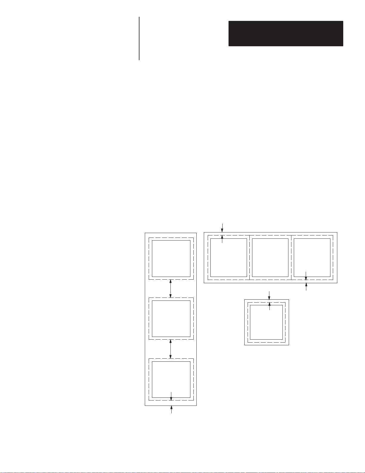
Panel Mounting Spacing Requirements
• Vertical stacking of modules: The lower edge of the top cutout must be
at least 6 inches (152mm) from the top edge of the lower cutout. The
enclosure must be at least 8 inches (203mm) deep.
• Horizontal mounting: Mount modules as close together as physically
possible. The enclosure must be at least 8 inches (203mm) deep.
• Mounting Screw Torque: Torque mounting screws to 8 lb-in (.908 N-m)
to ensure good seal between module gasket and panel.
B
B
A
A
Recommended minimum spacing:
A = 6 inches (152mm) from lower edge of top cutout to upper
B
edge of lower cutout
B = 1 inch (25.4mm) from outside edge of mounting flange
Depth of enclosure = 8 inches (203mm) or more.
B
3–5
Page 29
Chapter 3
Wiring and Installation
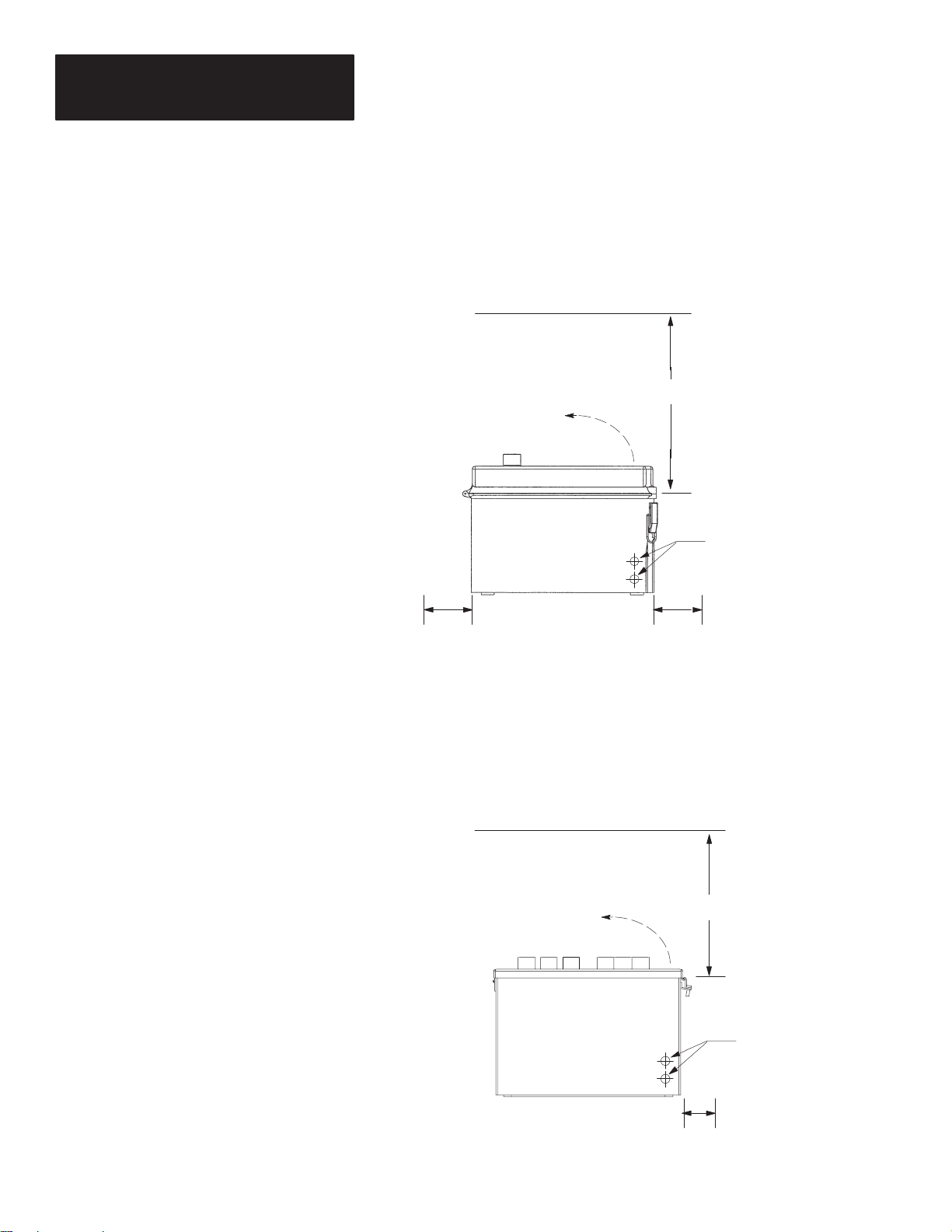
Fiberglass Enclosure Mounting Clearance Requirements
The enclosure mounting style requires a 2 inch (50 mm) clearance on the
latched side for opening and closing the enclosure cover. Adequate clearance
must be provided to allow for a minimum 90_ swing of the cover.
Clearance for Cover Swing
NOTE: If the wiring is run through the
bottom of the enclosure, it must be
secured to the tie wrap holders (provided).
The power wiring and the communications
wiring must be run through separate cutouts.
16 Button Module 13.5 (342.9)
32 Button Module 15.5 (393.7)
Wiring Cutouts (typical)
4.00
(101.6)
Clearance for latches and opening of adjacent door.
Additional clearance may be required depending on
wiring configuration.
4.00
(101.6)
Steel Enclosure Mounting Clearance Requirements
The mounting style requires a 3 inch (76 mm) clearance on the latched side
for opening and closing the enclosure cover. Adequate clearance must be
provided to allow for a minimum 90_ swing of the cover.
Clearance for Cover Swing
NOTE: If the wiring is run through the
bottom of the enclosure, it must be
secured to the tie wrap holders (provided).
The power wiring and the communications
wiring must be run through separate cutouts.
16 Button Module 13.5 (342.9)
32 Button Module 15.5 (393.7)
3–6
Wiring Cutouts (typical)
3.00
(76.2)
Clearance for latches and opening of adjacent door.
Additional clearance may be required depending on
wiring configuration.
Page 30
Chapter 3
Wiring and Installation
Spacing of 800T/H Modules
You can mount 16 and 32 Push Button 800T/H RediPANEL Modules in
either a vertical or horizontal orientation. To mount more than one
RediPANEL Push Button Module in the same enclosure, use a 1 inch (25.4
mm) minimum horizontal/vertical spacing between modules (measured at the
front panel).
16 Push Button 800T/H
Module Front Panel
1 inch (25.4 mm)
minimum clearance
32 Push Button 800T/H
Module Front Panel
3–7
Page 31

Chapter 3
Wiring and Installation
Installing the 800A and
Sealed Membrane Modules
Mounting tabs are built into the Module. After sliding the Module into the
enclosure, the tabs secure the Module until the mounting brackets are in
place. The installation procedure follows.
Mounting Tabs and Brackets
Mounting
Tabs
To install the 800A and Sealed Membrane Modules:
1. Cut an opening in the panel approximately 5.86 inch (148.84mm) H x
8.61 inch (218.69mm) W. See Figure 3.1.
3–8
Figure 3.1
Panel Cutout Dimensions in Inches (mm)
800A and Sealed Modules
9.25
(234.95)
1.06
(26.92)
0.62
(15.75)
➀ These 2 additional 0.312 inch (7.92 mm) diameter holes are required for NEMA Type 4X
push button modules.
7.375
(187.33)
Panel Cutout
5.86 x 8.61
(148.84 x 218.69)
➀
8.61
(218.69)
3.69
(93.73)
0.26
(6.60)
5.86
(148.84)
6.375
(161.93)
3.12 (79.25) Dia.
7.00
(177.8)
4 Places
Page 32

Figure 3.2
Depth Dimensions in Inches (mm)
800A and Sealed Modules
.12 (3.05)
Max Thickness
Chapter 3
Wiring and Installation
.44 (11.18)
Max Height of Buttons
.31
(7.87)
6.88
(174.75) Max.
2. Drill 4 (or 6) 0.312” (7.92mm) diameter holes for the top and bottom
mounting brackets.
3. Slide the Module through the opening. The mounting tabs help seat the
Module against an 1/16” (1.6mm) to 1/8” (3.2mm) thick enclosure.
4. To complete the mechanical installation, apply the mounting brackets and
tighten all the captive knurled thumbscrews. Figure 3.3 shows the
location of these screws. NOTE: Your unit may not have a mounting
bracket and thumbscrews. In that case, tighten the #10-32 nuts that are
provided to complete the installation.
Figure 3.3
Mounting Bracket Thumbscrews
Thumbscrews
Mounting Bracket
3–9
Page 33

Chapter 3
Wiring and Installation
Installing the 800EM/EP
Push Button Modules
The 800EM/EP Push Button Modules are available in 3 different
mounting styles:
• Panel Mounting
• Fiberglass Enclosure Mounting
• Steel Enclosure Mounting
This section shows how to install all 3 versions of the 16 and 32 Push Button
800EM/EP Modules.
800EM/EP Panel Mounting
To install a 16 or 32 Push Button 800EM/EP Faceplate Module:
1. Cut an opening in the panel approximately 12.55 inch (318.8mm) H x
12.75 inch (323.9mm) W. See Figure 3.4.
Figure 3.4
Panel Cutout Dimensions in Inches (mm)
800EM/EP Push Button Modules
14.25
(361.95)
.22 (5.59) Dia.
8 Places
14.25
(361.95)
12.55
(318.8)
12.75
(323.9)
6.64
(168.66)
Panel Cutout
13.28
(337.31)
3–10
6.64
(168.66)
13.28
(337.31)
Page 34

Figure 3.5
Depth Dimensions in Inches (mm)
800EM/EP Push Button Modules
Chapter 3
Wiring and Installation
.83
(21.1)
6.61
(167.9) Max.
2. Drill eight 0.22 in (5.59 mm) diameter holes for the top and bottom
mounting brackes.
3. Slide the module through the opening and against a 1/16 in (1.6 mm) to
1/8 in (3.2 mm) thick enclosure.
4. Fasten the module in place with the enclosed locking nuts. Alternately
.
tighten the nuts to a torque of 8 lb-in (0.908 N
m).
3–11
Page 35

Chapter 3
Wiring and Installation
800EM/EP Fiberglass Enclosure Mounting
To mount a 16 or 32 Push Button 800EM/EP Fiberglass Enclosure
Module:
1. Mark the locations of the four mounting holes. See Figure 3.6
Figure 3.6
Fiberglass Enclosure Mounting Dimensions in Inches (mm)
800EM/EP Push Button Modules
10.00
(254.0)
16 button module
12.00
(304.8)
32 button module
12.96
(329.2)
16 button module
14.96
(380.0)
32 button module
14.55
(369.6)
16 button module
16.55
(420.4)
32 button module
14.94
(379.5)
16 button module
16.94
(430.3)
32 button module
3–12
Fiberglass Enclosure
2. Drill four mounting holes suitable for your mounting hardware. The
mounting flange on the enclosure will acommodate a fastener up to
.50 in (12.7 mm) long x .31 in (7.9 mm) wide.
3. Secure the enclosure with the fastening hardware.
Page 36

Chapter 3
Wiring and Installation
800EM/EP Steel Enclosure Mounting
To mount a 16 or 32 Push Button 800EM/EP Steel Enclosure Module:
1. Mark the locations of the four mounting holes. See Figure 3.7.
Figure 3.7
Steel Enclosure Mounting Dimensions in Inches (mm)
800EM/EP Push Button Modules
14.75
(374.7)
16 button module
16.75
(425.5)
32 button module
15.50
(393.7)
16 button module
17.50
(444.5)
32 button module
10.00
(254.0)
16 button module
12.00
(304.8)
32 button module
12.94
(328.7)
16 button module
14.94
(379.5)
32 button module
Steel Enclosure
2. Drill four mounting holes suitable for your mounting hardware. The
mounting flange on the enclosure will acommodate up to a .25 in
(13 mm) diameter fastener.
3. Secure the enclosure with the fastening hardware.
3–13
Page 37

Chapter 3
Wiring and Installation
Installing the 800T/H
Push Button Modules
.50
(12.7)
.50
(12.7)
.50
(12.7)
6.00
(152.4)
4.00
(101.6)
This section shows how to install 32 and 16 Push Button 800T/H Modules:
To install a 32 Push Button 800T/H Module:
1. Cut an opening in the panel approximately 14 inches (355.60mm) W x 25
inches (635.0mm) H. See Figure 3.8
2. Drill fourteen 0.22 inch diameter holes for the mounting studs.
3. Slide the module through the opening.
4. Fasten the module in place with the enclosed locking nuts.
Figure 3.8
Mounting Dimensions in Inches (mm)
32 Button 800T/H Modules
6.00
(152.4)
4.00
(101.6)
1.50 (38.1)
Max. 800T
.50
(12.7)
.87
(22.1)
0.12
(3.2)
0.25 (6.4)
Gasket
8.49
(215.5)
0.62
(15.9)
Wire Loop
3–14
(152.4)
(152.4)
(152.4)
.50
(12.7)
6.00
6.00
6.00
.50
(12.7)
25.00
(635.0)
PANEL
CUTOUT
15.75
(393.7)
14.00
(355.6)
.22 (5.5) Dia.
(14 Places)
.87
(22.1)
26.75
(679.5)
24.50
(622.3)
#10-32 Mtg. Studs
(14 Places)
8.00
(203.2)
Page 38

1
1.00
(25.4)
.50
(12.7)
3.75
(95.3)
Chapter 3
Wiring and Installation
To install a 16 Push Button 800T/H Module:
1. Cut an opening in the panel approximately 14 inches (355.60mm) W x 15
inches (381.0mm) H. See Figure 3.9
2. Drill ten 0.22 inch diameter holes for the mounting studs.
3. Slide the module through the opening.
4. Fasten the module in place with the enclosed locking nuts.
Figure 3.9
Mounting Dimensions in Inches (mm)
16 Button 800T/H Modules
.50 (38.1)
Max. 800T
0.12
6.50
(165.1)
3.75
(95.3)
(12.7)
.87
(22.1)
.50
(3.2)
0.25 (6.4)
Gasket
8.49
(215.5)
0.62
(15.9)
Wire Loop
(165.1)
(165.1)
1.00
(25.4)
6.50
6.50
.50
(12.7)
15.00
(381.0)
PANEL
CUTOUT
15.75
(393.7)
14.00
(355.6)
.22 (5.5) Dia.
(14 Places)
.87
(22.1)
16.75
(419.1)
#10-32 Mtg. Studs
(14 Places)
8.00
(203.2)
14.50
(368.3)
3–15
Page 39

Chapter 3
Wiring and Installation
Connecting to a
Remote I/O Link
Connecting to
a Scanner Module
The Remote I/O link begins at the scanner module. The scanner modules
and controllers impose physical and logical limitations on the link.
• The push button module is addressed like a remote I/O rack.
• The link can have up to 32 remote I/O devices. Refer to the appropriate
PLC/SLC manual.
• The baud rate limits the maximum cable length (link distance):
Baud Rate Cable Length (Maximum)
57.6 K 3,000 meters (10,000 feet)
115.2K 1,500 meters (5,000 feet)
230.4K 750 meters (2,500 feet)
The connection to the link is through the Serial Data Link cable (Catalog No.
1770-CD). This cable wires into the connector plug of the module.
Connect the Push Button Module to the scanner module with the
Allen-Bradley I/O cable (Catalog No. 1770-CD) or Belden 9463.
A connector plug is provided with each Push Button Module. Wire the
connector to the I/O cable as shown below.
Wiring Connections for Communications Cable
2705 MODULE
CLEAR (LINE 2)
TWIN-AXIAL CABLE
MATING CONNECTOR
SHIELD
BLUE (LINE 1)
A Belden twin-axial cable links the RediPANEL Module to the Remote I/O
communications. It wires the mating connector of the user’s scanner module
to the mating connector of the 2705 module. It is recommended that you
terminate the first and last device on the remote I/O link. Install a 150 ohm,
1/2 watt resistor between lines 1 and 2 at both ends of the link for up to 16
devices and an 82 ohm, 1/2 watt resistor for up to 32 devices on the link.
3–16
Page 40

Chapter
Chapter Objectives
A–B
4
Programming the RediPANEL Modules
This chapter provides information on programming a RediPANEL module
from a PLC or SLC controller. For additional programming information
refer to the user manual for your controller or scanner module.
Section Page
Module Bit Addresses 4–1
Using a PLC-2 with a 1772-SD2 Scanner 4–9
Using a PLC-2 with a Sub I/O Scanner 4–11
Using a PLC-5 4–14
Using a PLC-5 with a Sub I/O Scanner 4–15
Operating Cycles 4–19
Response Time 4–20
Handshake Mode 4–21
Flashing Lamp Example 4–23
SLC-5/02 Programming Example 4–24
Module Bit Addresses
Each push button on the RediPANEL module is assigned a bit address. You
need to know these addresses when writing your PLC program. These bit
addresses are the same for all PLC processors.
This section shows the bit address locations for 8, 16 and 32 button modules.
Bit Addresses for 8 Button Modules (Type 800A only)
Octal and Decimal
00 01 02 03
1234
04 05 06 07
5678
The PLC example below shows where these bit addresses appear in your instruction address.
X X X
03 03
Bit Address
Push Button #4
Bit addresses 00 through 07 of the starting
I/O Group Numbers are assigned to lamps
and push buttons 1 through 8.
Starting I/O Group Number
X X X
Bit Address
for Lamp #4
4–1
Page 41

Chapter 4
Programming the RediPANEL Modules
PLC Bit Addresses (Octal) SLC Bit Addresses (Decimal)
Bit Addresses for 16 Button Modules
Bit Addresses for 16 Button
800A and NEMA Type 4X Membrane Modules
1 2 3 4 5 6
00 01 02 03 04 05
7 8 9 10 11 12
06 07 10 11 12 13
13 14
14 15
Front Panel
15 16
16 17
The PLC example below shows where these bit addresses appear in your instruction address.
The SLC example below shows where these bit addresses appear in your instruction address.
Button #
Address Bit #
Starting I/O Group Number
1 2 3 4 5 6
00 01 02 03 04 05
7 8 9 10 11 12
06 07 08 09 10 11
13 14
12 13
Front Panel
X X X
10 10
Bit Address
Push Button #9
Bit Address
for Lamp #9
15 16
14 15
X X X
4–2
Starting I/O Group Number
X X X
08 08
Bit Address
Push Button #9
Bit Address
for Lamp #9
X X X
Page 42

PLC Bit Addresses (Octal)
PB1
1
00
PB5
5
04
PB9
9
10
PB13
13
14
PB2
2
01
PB6
6
05
PB10
10
11
PB14
14
15
PB3
3
02
PB7
7
06
PB11
11
12
PB15
15
16
PB4
4
03
PB8
8
07
PB12
12
13
PB16
16
17
Bit Addresses for 16 Button
800EM/EP Modules
Cable #
Button #
Address Bit #
Front Panel Views
Chapter 4
Programming the RediPANEL Modules
SLC Bit Addresses (Decimal)
PB1
1
00
PB5
5
04
PB9
9
8
PB13
13
12
PB2
2
01
PB6
6
05
PB10
10
9
PB14
14
13
PB3
3
02
PB7
7
06
PB11
11
10
PB15
15
14
PB4
4
03
PB8
8
07
PB12
12
11
PB16
16
15
In 800EM/EP Push Button Modules, the
cables that connect to the push buttons are
marked PB1 – PB16 and diagnostics. This
corresponds to PLC input and output bit
locations 00-17.
The PLC example below shows where these bit addresses appear in your instruction address.
X X X
13 13
The SLC example below shows where these bit addresses appear in your instruction address.
X X X
Starting I/O Group Number
Bit Address
Push Button #12
Starting I/O Group Number
In 800EM/EP Push Button Modules, the
cables that connect to the push buttons are
marked PB1 – PB16 and diagnostics. This
corresponds to SLC input and output bit
locations 00-15.
X X X
Bit Address
for Lamp #12
X X X
11 11
Bit Address
Push Button #12
Bit Address
for Lamp #12
4–3
Page 43

Chapter 4
Programming the RediPANEL Modules
PLC Bit Addresses (Octal)
Bit Addresses for 16 Button
800T/H Modules
SLC Bit Addresses (Decimal)
A00 A01 A02 A03
1234
00 01 02 03
A04 A05 A06 A07
5678
04 05 06 07
A10 A11 A12 A13
9101112
10 11 12 13
A14 A15 A16 A17
13 14 15 16
14 15 16 17
In 800T/H Push Button Modules, the cables
that connect to the push buttons are marked
A00-A17. This corresponds to PLC input
and output bit locations 00-17.
The PLC example below shows where these bit addresses appear in your instruction address.
Cable #
Button #
Address Bit #
Front Panel Views
Starting I/O Group Number
A00 A01 A02 A03
1234
00 01 02 03
A04 A05 A06 A07
5678
04 05 06 07
A10 A11 A12 A13
9101112
08 09 10 11
A14 A15 A16 A17
13 14 15 16
12 13 14 15
In 800T/H Push Button Modules, the cables
that connect to the push buttons are marked
A00-A17. This corresponds to SLC input
and output bit locations 00-15.
X X X
13 13
The SLC example below shows where these bit addresses appear in your instruction address.
Bit Address
Push Button #12
Starting I/O Group Number
Bit Address
for Lamp #12
X X X
11 11
Bit Address
Push Button #12
Bit Address
for Lamp #12
X X X
X X X
4–4
Page 44

PLC Bit Addresses (Octal)
Chapter 4
Programming the RediPANEL Modules
Bit Addresses for 32 Button Modules
Bit Addresses for 32 Button 800A Modules
21 345678
01
00
10
11
9
11
17 18 19
26
25 27 28 29 30 31
11 151413
10
SLC Bit Addresses (Decimal)
21 345678
01
00
10
9
09
12 13 14 15 16
13
12
20 21 22 23 24
12
Front Panel
12 13 14 15 16
11
11
10
Button #
0605040302
07
17
16
151410
0605040302 070100
32
1716
07
0605040302
14
15
131208
Two Module Groups (or words) of bit addresses are needed for the 32 push buttons:
D Bit addresses 00 through 07 and 10 through 17 of the starting I/O group are
D Bit addresses 00 through 07 and 10 through 17 of the next I/O group are
Two Module Groups (or words) of bit addresses are needed for the 32 push buttons:
Bit Address #
assigned to the lamps and push buttons 1 through 16.
assigned to the lamps and push buttons 17 through 32.
Button #
Bit Address #
17 18 19
26
25 27 28 29 30 31
09 131211
08
20 21 22 23 24
0605040302 070100
10
Front Panel
D Bit addresses 00 through 15 of the starting I/O group are assigned to the lamps
and push buttons 1 through 16.
32
1514
See the next section for PLC and SLC addressing examples.
D Bit addresses 00 through through 15 of the next I/O group number are
assigned to the lamps and push buttons 17 through 32.
4–5
Page 45

Chapter 4
Programming the RediPANEL Modules
PLC Bit Addresses (Octal)
*PB1 PB2 PB3 PB4
1 2
00 01 02 03
PB8
PB7
7
07
06
PB14
PB13
14
13
15
14
PB20
PB19
20
19
03
02
PB26
PB25
26
25
11
10
PB32
PB31
32
31
17
16
3 4
PB10
PB9
9
8
10
PB16
PB15
15
16
PB22
PB21
21
04
PB28
PB27
27
12
16
17
28
13
10
11
22
05
PB5
5
04
PB11
11
12
PB17
17
00
PB23
23
06
PB29
29
14
PB6
6
05
PB12
12
13
PB18
18
01
PB24
24
07
PB30
30
15
Bit Addresses for 32 Button
800EM/EP Modules
Cable #
Button #
Address Bit #
Front Panel Views
See next section for
PLC/SLC addressing examples.
SLC Bit Addresses (Decimal)
*PB1 PB2 PB3 PB4
1 2
00 01 02 03
PB8
PB7
7
07
06
PB14
PB13
14
13
13
12
PB20
PB19
20
19
03
02
PB26
PB25
26
25
09
08
PB32
PB31
32
31
15
14
3 4
PB10
PB9
10
9
8
09
08
PB16
PB15
16
15
15
14
PB22
PB21
22
21
05
04
PB28
PB27
28
27
11
10
PB5
5
04
PB11
11
10
PB17
17
00
PB23
23
06
PB29
29
12
PB6
6
05
PB12
12
11
PB18
18
01
PB24
24
07
PB30
30
13
When using a PLC with 800EM/EP Push Button Mod-
*
ules, the cables that connect to the push buttons are
marked PB1 – PB32 and diagnostics. This corresponds
to PLC input and output bit locations 00 – 17.
Two Module Groups (or words) of bit addresses
are needed for the 32 push buttons:
D Bit addresses 00 through 07 and 10 through
17 of the starting I/O group are assigned to
the lamps and push buttons 1 through 16.
D Bit addresses 00 through 07 and 10 through
17 of the next I/O group number are assigned
to the lamps and push buttons 17 through 32.
4–6
*
When using an SLC with 800EM/EP Push Button Modules, the cables that connect to the push buttons are
marked PB1 – PB32 and diagnostics. This corresponds
to SLC input and output bit locations 00 – 15.
Two Module Groups (or words) of bit addresses
are needed for the 32 push buttons:
D Bit addresses 00 through 15 of the starting I/O
group are assigned to the lamps and push
buttons 1 through 16.
D Bit addresses 00 through 15 of the next I/O
group number are assigned to the lamps and
push buttons 17 through 32.
Page 46

PLC Bit Addresses (Octal)
Chapter 4
Programming the RediPANEL Modules
Bit Addresses for 32 Button
800T/H Modules
SLC Bit Addresses (Decimal)
*A00 A01 A02 A03
1 2
00 01 02 03
A04 A05 A06 A07
5
04 05 06 07
A10 A11 A12 A13
9
10 11 12 13
A14 A15 A16 A17
13
14 15 16 17
B00 B01 B02 B03
17
00 01 02 03
B04 B05 B06 B07
21
04 05 06 07
B10 B11 B12 B13
25
10 11 12 13
B14 B15 B16 B17
29
14 15 16 17
10
14
18
22
26
30
6
3 4
7
11 12
15 16
19 20
24
23
27 28
31
32
8
Cable #
Button #
Address Bit #
Front Panel Views
See next section for PLC/SLC addressing examples.
*A00 A01 A02 A03
1 2
00 01 02 03
A04 A05 A06 A07
5
04 05 06 07
A10 A11 A12 A13
10
9
08 09 10 11
A14 A15 A16 A17
13
14
12 13 14 15
B00 B01 B02 B03
17
18
00 01 02 03
B04 B05 B06 B07
22
21
04 05 06 07
B10 B11 B12 B13
26
25
08 09 10 11
B14 B15 B16 B17
29
30
12 13 14 15
6
3 4
7
11 12
15 16
19 20
24
23
27 28
31
32
8
* *
When using a PLC with 800T/H Push Button Modules,
the cables that connect to the push buttons are marked
A00-A17 & B00-B17. This corresponds to the input and
output bit locations as shown. “A” refers to the 1st word;
“B” refers to the 2nd word.
Two Module Groups (or words) of bit addresses
are needed for the 32 push buttons:
D Bit addresses 00 through 07 and 10 through
17 of the starting I/O group are assigned to
the lamps and push buttons 1 through 16.
D Bit addresses 00 through 07 and 10 through
17 of the next I/O group number are assigned
to the lamps and push buttons 17 through 32.
When using an SLC with 800T/H Push Button Modules,
the cables that connect to the push buttons are marked
A00-A17 & B00-B17. This corresponds to the input and
output bit locations as shown. “A” refers to the 1st word;
“B” refers to the 2nd word.
Two Module Groups (or words) of bit addresses
are needed for the 32 push buttons:
D Bit addresses 00 through 15 of the starting I/O
group are assigned to the lamps and push
buttons 1 through 16.
D Bit addresses 00 through 15 of the next I/O
group number are assigned to the lamps and
push buttons 17 through 32.
4–7
Page 47

Chapter 4
Programming the RediPANEL Modules
Addressing Examples for 32 Button Modules
Below are PLC and SLC addressing examples for the 32 button modules.
The PLC example below shows where these bit addresses appear in your instruction address.
Starting I/O Group Number (Word)
X X X
07 07
Bit Address
Push Button #8
Starting I/O Group Number (Word) +1
Bit Address
for Lamp #8
X X X
10 10
The SLC example below shows where these bit address will appear in your instruction address.
Bit Address
Push Button #25
Starting I/O Group Number (Word)
Bit Address
for Lamp #25
X X X
X X X
4–8
X X X
06 06
Bit Address
Push Button #7
Starting I/O Group Number (Word) +1
Bit Address
for Lamp #7
X X X
10 10
Bit Address
Push Button #27
Bit Address
for Lamp #27
X X X
X X X
Page 48

Chapter 4
Programming the RediPANEL Modules
Using a PLC-2 with a 1772-SD2 Scanner
When using a PLC-2/20 or 2/30 with a RediPANEL module, the system must
include a 1772-SD2 Remote I/O Scanner/Distribution Panel (or a 1771-SN
Sub I/O Scanner Module). The 1772-SD2 allows the PLCs to communicate
with as many as 16 remote I/O devices in any configuration totaling 7 logical
racks of I/O or less.
For details on 1771-SD2 wiring connections and switch settings, see
Publication No. 1772-2.18 (The Remote I/O Scanner/Distribution Panel).
Programming Example
Switch Bank #1 on the RediPANEL Module is set to use:
• Rack Address 2 (switch settings 1 - 6)
• Module Group 0 (switch settings 7 and 8)
Figure 4.1 shows typical address instructions and how these instructions are
used in your PLC-2/20 or 2/30 program.
Figure 4.1
PLC-2/20 or 2/30 Programming Example
Press Push
Button #1
00 01 02 03
123 4
04 05 06 07
567 8
10 11 12 13
9101112
14 15 16 17
13 14 15 16
Push Button #1
Illuminate Push
Button #4
Input
00
00 03
Rack #2
Module Group 0
Bits
Push Button #4 Lamp
020120
Module Group 0
Output
020120
03
4–9
Page 49

Chapter 4
Programming the RediPANEL Modules
120
After entering the ladder logic, place the PLC in the RUN or REMOTE RUN
mode to test your logic. Monitor the ON/OFF status of the input and output
bits of the RediPANEL push button module by pressing [SEARCH] 53
followed by the address to monitor. This displays the input or output image
table for that address.
The following figure shows what the I/O image table looks like when you
press push button #1 for the previous example.
00
Input Image Table
1/4 Rack
00000 00001 00000 0 0001
Switch Status Bits
Push Button #1, Illuminate the Lamp in Button #4
Output Image Table
1/4 Rack
Module Group
012345671011121314151617 012345671011121314151617
(Word)
0
1
Lamp Control Bits
Special Considerations
If the MODE SELECT DIP Switch #5 (Fault Table) on the 1772-SD2 is set
to OFF, a remote I/O fault table is generated and remote I/O rack #2 must be
declared used. These fault status bits are generated in the addresses
associated with Module Groups 5 and 6 of remote I/O rack #2. (See
Publication 1772-2.18).
03
4–10
Page 50

Chapter 4
Programming the RediPANEL Modules
Using a PLC-2 with a Sub I/O Scanner
When using a PLC-2 processor with RediPANEL module, the system must
contain a 1771-SN Sub I/O Scanner. Mini PLC-2 processors communicate
with remote I/O using this Sub I/O Scanner. The Sub I/O Scanner is located
in the same chassis as the mini PLC-2 and communicates with the PLC using
block transfers. The 1771-SN Sub I/O Scanner looks like an intelligent I/O
module to the PLC. You can also use Sub I/O Scanner in any chassis of a
PLC-2/20 or 2/30 system.
The 1771-SN requires one PLC scan to receive the output data from the
output image table and another PLC scan to send discrete input data to the
input image table. Anything connected to the Sub I/O Scanner is scanned
asynchronous to the PLC scan. The PLC then scans the Sub I/O Scanner
during the I/O portion of the PLC scan. See the section on Operating Cycles.
Block Transfer Example
Figure 4.2 shows an example of a block transfer between a Sub I/O Scanner
module and a PLC.
Figure 4.2
Block Transfer between Sub I/O Scanner and PLC–2
Read information from the sub-scanner into the PLC.
1
Write information to the sub-scanner from PLC.
2
Buffer the read information from the sub-scanner.
110
3
] [
17
BLOCK X-FER READ
DATA ADDR: 0030
MODULE ADDR: 101
BLOCK LENGTH: 014
FILE: 0200-0215
BLOCK X-FER WRITE
DATA ADDR: 0031
MODULE ADDR: 101
BLOCK LENGTH: 014
FILE: 0300-0315
FILE TO FILE MOVE
DATA ADDR: 0033
POSITION: 001
FILE LENGTH: 014
FILE A: 0200-0215
FILE R: 0400-0415
RAT PER SCAN: 014
010
( EN )
17
110
( DN )
17
010
( EN )
16
110
( DN )
16
010
( EN )
16
110
( DN )
16
4–11
Page 51

Chapter 4
Programming the RediPANEL Modules
Ladder Logic Description
The block transfer Read and Write instructions in the first two rungs move
information between the Sub I/O Scanner and the PLC-2. You must assign
the block transfer instructions to the first available timer/counter location.
The length of the block transfer is equal to eight words (for the Sub I/O
Scanner utility functions) plus 2 words for each 1/4 rack of I/O image table
your module requires. For additional information on block transfers, see
your PLC-2 User’s Manual.
The File To File Move in rung 3 is triggered by the Done bit of the block
transfer Read instruction. The File To File Move serves as a buffer for the
block transfer Read data.
Block Transfer Read Instruction
Reads input data from the Sub I/O Scanner and transfers that data to the
Input Data File in the PLC starting with word 200. The File To File Move is
a buffer for this information. The input data transferred to word files 200 215 will immediately (after Block Transfer Read done bit is set) move to
word files 400 - 415. The input addresses will start at 4 instead of 1.
Block Transfer Write Instruction
Writes output data to the Output Data File in the PLC (300 - 315) and then
transfers it to the Sub I/O scanner. Output addresses start at 3 instead of 0.
Helpful Hint
If you start your word files with hundred numbers, (200, 300 or 400), the rest
of the instruction address is similar to hardwired I/O. The 2nd number in the
address equals the rack number, the 3rd number equals the module group
number (word), and the 4th and 5th numbers equal the bit location. For more
details on the Sub I/O Scanner, refer to Sub I/O Scanner Module Product
Data (Publication No. 1771-2.184).
4–12
Page 52

Chapter 4
Programming the RediPANEL Modules
Figure 4.3 shows instruction addresses for a Mini PLC-2 with a Sub I/O
Scanner connected to a RediPANEL module. The module is configured as
rack #1, module group 0.
Figure 4.3
Remote I/O Addressing with a Sub I/O Scanner
When button #1 (410/00) is pressed, turn on its lamp (310/00).
410
][
00
When button #2 (410/01) is pressed, turn on its lamp (310/01).
410
][
01
310
()
00
310
()
01
Rack
Module Group (Word)
400
01
02
03
04
05
06
07
Switch Status Bits
410
11
12
The following figure shows the I/O Data File configurations for the examples
in Figures 4.2 and 4.3.
Rack
INPUT DATA FILE OUTPUT DATA FILE
300
Reserved space for
sub-scanner utility words.
012345671011121314151617
000000
0011
310
Module Group (Word)
01
02
03
04
05
06
07
Lamp Control Bits
11
12
Reserved space for
sub-scanner utility words.
000000
012345671011121314151617
0011
13
14
15
Input Data
13
Output Data
14
15
4–13
Page 53

Chapter 4
Programming the RediPANEL Modules
Using a PLC-5
The PLC-5/15 and 5/25 processors have built-in remote I/O scanners. No
additional hardware is required. Run the two conductor shielded cable (Blue
Hose) from the RediPANEL to the remote I/O port of the PLC-5.
To use the built-in scanner:
• Set switch 8 in DIP Switch Bank SW-1 on the processor to the OPEN,
OFF or Scanner Mode position.
• Set the baud rate on the RediPANEL module to 57.6K baud for a
PLC-5/15 or -5/25.
For an enhanced processor the baud rate can be 57.6K, 115.2K or 230.4K.
Programming Example
Switch Bank #1 on the RediPANEL Module is set to use:
• Rack Address 3 (switch settings 1 - 6)
• Module Group 4 (switch settings 7 and 8)
Figure 4.4 shows typical address instructions and how these instructions are
used in your PLC-5/15 or -5/25 program.
00 01 02 03
1234
04 05 06 07
567 8
10 11 12 13
9101112
14 15 16 17
13 14 15 16
Figure 4.4
PLC–5/15, -5/25 Programming Example
Input
I: 034
01 01
Push Button #2
01
Rack #3
Module Group 4
Module Group 4
Output
O:034
Bits
Push Button #2 Lamp
O:034I: 034
01
4–14
Page 54

Chapter 4
Programming the RediPANEL Modules
Using a PLC-5 with a Sub I/O Scanner
Use a 1771-SN Sub I/O Scanner with a PLC-5 processor when the
application requires more remote devices than the processor can
accommodate. The Sub I/O Scanner module can communicate to 16
additional remote I/O devices. Locate the 1771-SN Sub I/O scanner in the
same rack as the PLC-5 (the local rack) or in anyone of the remote racks
supported by the processor.
The PLC-5 communicates with the Sub I/O Scanner using block transfer read
and write instructions. The block transfer read instruction reads input data
from the Sub I/O Scanner and transfers that data to integer files in the PLC.
The block transfer write instruction writes output data to files in the PLC,
then transfers that data to the Sub I/O Scanner. Input and output addresses
begin at the integer file assigned to the block transfer instruction (instead of
Input addresses starting with “I” and Output addresses starting with “O”).
The rest of the input addresses depend on the specific integer file designated
as the Data File in the block transfer read instruction. The rest of the output
address depends on the specific integer file designated as the Data File in the
block transfer write instruction.
Figure 4.5 an example of a bidirectional block transfer between a Sub I/O
Scanner and a PLC-5.
Figure 4.5
PLC-5 Block Transfer
BTR
Enable Bit
N10:0
]
[
/
15
BTW
Enable Bit
N10:5
]
[
/
15
BTW
Enable Bit
N10:5
]
[
/
15
BTR
Enable Bit
N10:0
]
[
/
15
Read from Sub-Scanner to the PLC-5 .
Write to the Sub-Scanner from the PLC-5 .
BTR
BLOCK TRNSFR READ
RACK 0
GROUP 7
MODULE 1
CONTROL BLOCK N10:0
DATA FILE N11:0
LENGTH 20
CONTINUOUS N
BTW
BLOCK TRNSFR WRITE
RACK 0
GROUP 7
MODULE 1
CONTROL BLOCK N10:5
DATA FILE N12:0
LENGTH 20
CONTINUOUS N
( EN )
( DN )
( ER )
( EN )
( DN )
( ER )
4–15
Page 55

Chapter 4
Programming the RediPANEL Modules
Parameter Description Notes
Rack Number of I/O rack in which the I/O scanner is located. Consult PLC manual
Group Number of I/O group in rack. 0 - 7
Module Number of slot in I/O group in which the sub I/O scanner is
located.
Control Block 5-word integer file that controls the instruction’s operation.
This is not the fil type for control elements, R
Data File Address that the processor uses to transfer data (writing to
or reading from).
Block Transfer Read and Write Instruction Parameters
Program all block transfer read and write instructions in the first rungs of
your program. Each instruction transfers a maximum of 64 words between
the processor and the sub I/O scanner. There are 8 words for the sub I/O
scanner utility functions and 8 words for each of the 7 logical racks of
RediPANELs the sub I/O scanner can communicate with.
The block transfer read and write instructions have certain parameters that
you must enter. They are as follows:
0 or 1
Enter the integer file address without the # symbol.
For example, N7: (any integer file) not #N7:.
Enter file address without the # symbol.
Length Number of words the sub I/O scanner is transferring. 8 words (for Sub I/O Scanner utility functions) plus 2 words for
each 1/4 rack of I/O the Sub I/O Scanner communicates with.
The Length is 20 for the following example:
4 RediPANELS configured for 1/4 rack
1 RediPANEL configured for 1/2 rack to the Sub Scanner
8 words (Sub I/O Scanner utility functions)
8 words (2 words for each 1/4 RediPANEL)
+ 4 words (for one 1/2 rack RediPANEL)
20 words
Continuous Mode of instruction execution. Enter N for No.
4–16
Page 56

Chapter 4
Programming the RediPANEL Modules
Programming Example
The Sub I/O Scanner is in slot 1, module group 7 of the local I/O rack. The
Sub I/O Scanner is connected to three RediPANEL 16 button modules, each
configured for 1/4 rack.
• The Block Transfer Length is 14 (8 words for utility functions and 2
words for each of the 3 RediPANELS configured for 1/4 rack.
• Data File address for the block transfer read starts at N11:0. This means
that addresses for RediPANEL buttons start at N11:8.
The Data File for the block transfer write starts at N12:0. This means
addresses for the RediPANEL lamps start with N12:8.
Figure 4.6
PLC-5/15 and Sub I/O Scanner Programming Example
1771-SN
(Sub I/O Scanner)
PLC-
01234567 01234567 01234567
5/15
1771-I/O
(Local Rack 0)
N10:0
] / [
15
N10:5
] / [
15
1771
ASB
1771-I/O
(Remote 1)
16 Button
RediPANEL
16 Button
RediPANEL
16 Button
RediPANEL
1771
ASB
1771-I/O
(Remote 2)
BTR
BLOCK TRNSFR READ
RACK 0
GROUP 7
MODULE 1
CONTROL BLOCK N10:0
DATA FILE N11:0
LENGTH 14
CONTINUOUS N
70123456
1771
ASB
1771-I/O
(Remote 3)
( EN )
( DN )
( ER )
N10:5
] / [
15
N10:0
]
/
15
BTW
[
BLOCK TRNSFR WRITE
RACK 0
GROUP 7
MODULE 1
CONTROL BLOCK N10:5
DATA FILE N12:0
LENGTH 14
CONTINUOUS N
( EN )
( DN )
( ER )
4–17
Page 57

Chapter 4
Programming the RediPANEL Modules
Input Addresses
N11:00/00 - N11:07/15
Reserved for Sub-Scanner Utility Functions
N11:08/00 - N11:09/15
Reserved for button addresses for Module 1
configured for rack 1, module group 0 and 1
N11:10/00 - N11:11/15
Reserved for button addresses for Module 2
configured for rack 1 module group 2 and 3
N11:12/00 - N11:13/15
Reserved for button addresses for Module 3
configured for rack 1 module group 4 and 5
Figure 4.7 shows the instruction addresses for the RediPANEL Module
configuration in Figure 4.6 The first 8 words of files N11 and N12 are
reserved for the Sub I/O Scanner utility functions.
Figure 4.7
PLC-5/15 and Sub I/O Scanner Ladder Logic Example
RediPANEL
Address Profile
Output Addresses
N12:00/00 - N12:07/15
Reserved for Sub-Scanner Utility Functions.
N12:08/00 - N12:09/15
Reserved for lamp addresses for Module 1
configured for rack 1 module group 0 and 1
N12:10/00 - N12:11/15
Reserved for lamp addresses for Module 2
configured for rack 1 module group 2 and 3
N12:12/00 - N12:13/15
Reserved for lamp addresses for Module 3
configured for rack 1 module group 4 and 5
Module 1
Push Button #16
N11:08
15 15
Module 3
Push Button #15
N11:12
14 14
Module 1
Lamp #16
N12:08
Module 3
Lamp #15
N12:12
4–18
Page 58

Chapter 4
Programming the RediPANEL Modules
Operating Cycles
The figure below illustrates a single operating scan or cycle of a PLC
processor.
End of program scan.
One cycle = Program scan + I/O scan
I/O scan: Status of inputs is noted and
outputs are energized.
Start of program scan. Instructions are
scanned sequentially, as entered.
On power up, the processor begins a scan of the user program.
• The PLC scans the input/output (I/O) devices to determine their status.
• During the I/O update scan, the PLC communicates with the scanner.
• The scanner performs a remote I/O scan, asynchronous to the PLC’s scan.
The I/O chassis connected to the scanner are scanned in sequential order
according to the I/O rack number, regardless of I/O channel.
The remote I/O scan time varies according to the amount of I/O data change
taking place. Data from the input devices is transferred to the PLC’s input
image table and data from the PLC’s output image table is transferred to the
output devices. After completing the I/O scan, the processor begins the
program scan. At this time, all ladder logic program instructions are scanned
and executed in the order in which they were entered.
The I/O scan and the program scan are performed one after the other. The
operating cycle is the total time required for both the I/O scan and the
program scan.
The sections on Response Time and Handshake Mode cover the importance
of timing in the program portion of the cycle in contrast to the I/O portion.
4–19
Page 59

Chapter 4
Programming the RediPANEL Modules
Response Time
Response time is the amount of time it takes the RediPANEL Module to
respond to a depression of a button.
The RediPANEL Module uses the Scanner Module to tell the PLC when a
button is pressed. The Scanner Module takes a maximum of 7.0 milliseconds
to scan a device, unless there is electrical noise. A maximum of 16 physical
devices may be connected to any single Scanner Module channel. The
maximum time between reading button depressions is:
7.0 milliseconds/device × 16 devices = 112 milliseconds
The worst case occurs when a second button is pressed while a 64 word
block transfer is pending. A calculation for this condition is:
0.5 milliseconds/word × 64 words = 32 milliseconds
When you add these two figures together, you get:
112 milliseconds + 32 milliseconds = 144 milliseconds
Therefore, if a button is pressed, released and pressed again within 144
milliseconds, the second press is missed by the Scanner Module. To deal
with the response time factor:
1. The RediPANEL Module maintains each press of a push button in
the ON state for a minimum of 100 milliseconds (in the Timed Mode) or
until it is recognized by the PLC (in the Handshake Mode).
2. The push button must be released for 50 milliseconds between
presses or the second press is ignored.
4–20
Page 60

Chapter 4
Programming the RediPANEL Modules
Handshake Mode
RediPANEL Modules have a standard TIMED feature that holds all push
button depressions for a minimum of 100 milliseconds allowing the PLC to
read the depression during its scan cycle. No programming is required.
Most system configurations use this feature to insure data capture of a push
button depression.
Handshaking is required only under certain conditions.
1. Lengthy scan times. Lengthy scan times occur when the block
transfer instruction is used numerous times in the ladder program.
Lengthy scan times also occur with large ladder programs.
2. When the remote I/O link is approaching its physical limitation of 16
devices (RediPANEL modules, keypad modules, remote I/O racks).
To select the Handshake feature, enable (set ON) the module’s DIP switch 7
of Switch Bank #2. Setting this switch OFF, gives you the TIMED feature,
which is the default setting. Chapter 2 discusses switch settings for mode
configuration. Figure 2.3 refers to Handshake enable and disable settings.
To use the Handshake feature, the PLC program must have a rung that
accepts the handshake bit and allows communication to continue. Figure
4.8 shows an example rung. Your PLC program must
contain this rung or
the module will not operate.
Figure 4.8
Ladder Logic Handshake Rung
Input Handshake Bit Output Handshake Bit
17 17
If handshake is enabled and the handshake rung is in the user’s program, the
RediPANEL module holds all push button input signals high for a minimum
of one complete PLC program scan. The signal(s) remain high for one
complete cycle of the handshake input bit. The handshake input and output
signals continuously toggle independent of any push button closures. The
handshake function is operational even if no push buttons have been pressed.
4–21
Page 61

Chapter 4
Programming the RediPANEL Modules
Figure 4.9 shows handshake timing diagrams. They are not precise timing
diagrams. Timing varies from application to application and is dependent
upon the number of remote I/O nodes, program scan time, etc.
Figure 4.9
Handshake Timing Diagrams
PLC Scan Cycle
Handshake Input Bit 17
Handshake Output Bit 17
Read Inputs
Write to Outputs
Program Scan
Push Button Contact
Push Button Input
Handshake holds the push button input high even if the push button contact signal goes low.
4–22
Page 62

Chapter 4
Programming the RediPANEL Modules
PLC-5 – Flashing Lamp
Example
The ladder diagram in Figure 4.10 shows how to flash a lamp with a button.
The program uses Rack 2, group 0 and bit location 0 (Push Button #1) with
Lamp #6 for the output.
For applications in which a RediPANEL Module communicates via a scanner
module this is the only programming that is necessary.
Figure 4.10
Flashing a Button Lamp
When button #1 (I:20/00) is pressed, turn on lamp for button #6 (O:20/05).
I:20
][
00
When button #2 (I:20/01) is pressed along with push button #1, flash lamp #6 (O:21/05).
I:20
][
01
O:20
()
05
O:21
()
05
4–23
Page 63

Chapter 4
Programming the RediPANEL Modules
SLC 5/02 Programming Example
The example in this section interfaces a RediPANEL module with an SLC
5/02 controller. An alarm, connected to an output module, signals when
communications with the RediPANEL are lost. The system consists of:
• SLC 5/02 Processor (Catalog No. 1747-L524) in slot 0
• Remote I/O Scanner (Catalog No. 1747-SN) in slot 1
• Output Module (Catalog No. 1746-OB8) in slot 2
• An alarm connected to the output module
• Bulletin 2705 RediPANEL Module
Alarm
RIO NETWORK
Push Button Module
The 1747-SN Scanner can address four racks (0-3). 32 input words and 32
output words may be addressed in
1
/4, 1/2, 3/4, or full rack format. The
scanner module can connect to 16 Remote I/O devices.
4–24
Page 64

Chapter 4
Programming the RediPANEL Modules
The G File contains the configuration information for communications
between the RediPANEL module and the SLC 5/02.
• Word 0 of the G File indicates the I/O mix of the scanner. You cannot
modify the contents of the G File’s word 0.
• Word 1 of the G File defines the RIO rack address and starting group for
each network device.
• Word 2 of the G File specifies the size of the network device.
You can only modify the contents of the G File in the offline mode. The file
is then downloaded to the SLC processor.
Example G File
Bit Number
I/O Mix, Word 0
Device Address, Word 1
Device Size, Word 2
15 14 13 12 11 10 9 8 7 6 5 4 3 2 1 0
0
0 1 0 0 0 0 0 0 0 1 0 0 0 0 0
RIO Rack 3
Staring
Group
64 0
1
00
11100110
Note: The 1747-SN Scanner does not support block transfer functions. Refer to scanner user manual
for additional information on scanner configuration.
RIO Rack 2
Staring
Group
64 64
0
001
RIO Rack 1
Staring
Group
0
0001
1111
RIO Rack 0
Staring
Group
20462022 0
1001
1001
= 2219H
= E6F9H
(2) Quarter Rack devices, Starting Group 0 & 6
Full Rack Device, Starting Group 0
Half Rack Device, Starting Group 2
Three Quarter Rack Device, Starting Group 2
4–25
Page 65

Chapter 4
Programming the RediPANEL Modules
The scanner input file is shown below. The output file is similar; it is
addressed O:1.0 to O:1.3
Rack 0
Rack 1
Rack 2
Rack 3
Rack 0 Group 0
Rack 0 Group 1
Rack 0 Group 2
Rack 0 Group 3
Rack 0 Group 4
Rack 0 Group 5
Rack 0 Group 6
Rack 0 Group 7
Rack 1 Group 0
Rack 1 Group 1
Rack 1 Group 2
Rack 1 Group 3
Rack 1 Group 4
Rack 1 Group 5
Rack 1 Group 6
Rack 1 Group 7
Rack 2 Group 0
Rack 2 Group 1
Rack 2 Group 2
Rack 2 Group 3
Rack 2 Group 4
Rack 2 Group 5
Rack 2 Group 6
Rack 2 Group 7
Rack 3 Group 0
Rack 3 Group 1
Rack 3 Group 2
Rack 3 Group 3
Rack 3 Group 4
Rack 3 Group 5
Rack 3 Group 6
Rack 3 Group 7
Bit Number (octal)
Bit Number
Word 0
Word 1
Word 2
Word 3
Word 4
Word 5
Word 6
Word 7
Word 8
Word 9
Word 10
Word 11
Word 12
Word 13
Word 14
Word 15
Word 16
Word 17
Word 18
Word 19
Word 20
Word 21
Word 22
Word 23
Word 24
Word 25
Word 26
Word 27
Word 28
Word 29
Word 30
Word 31
0123456789101112131415
Input File
I:1.0
I:1.1
I:1.2
RediPANEL
I:1.3
not used
not used
not used
not used
not used
not used
not used
not used
not used
not used
not used
not used
not used
not used
not used
not used
not used
not used
not used
not used
not used
not used
not used
not used
not used
not used
not used
not used
1
4
16
17
8
14
8
8158
11
8128138
5
8
86878108
2
8
838
I:1.4
I:1.5
I:1.6
I:1.7
I:1.8
I:1.9
I:1.10
I:1.11
I:1.12
I:1.13
I:1.14
I:1.15
I:1.16
I:1.17
I:1.18
I:1.19
I:1.20
I:1.21
I:1.22
I:1.23
I:1.24
I:1.25
I:1.26
I:1.27
I:1.28
I:1.29
I:1.30
I:1.31
0
8
4–26
The BAUD rate is 115.2K. DIP. Switch 1 must be in the OFF position; DIP
switch 2 must be ON.
The G file size is set to 3 using the Speciality I/O Configuration function.
The M0 and M1 file sizes are set to 32 in the Advanced Set Up function.
Since only the first 4 words of the input and output files contain valid
information, the scanned input and output words can be set to 4. Reducing
the number of scanned input and output words decreases SLC scan time.
Configuration information is entered in the Modify G File function. Word 0
is reserved and cannot be modified. Word 1 indicates the starting address of
the device, word 2 indicates its size.
Page 66

Chapter 4
Programming the RediPANEL Modules
Address Conversion
The addresses for the Input and Output files are provided in an octal format.
You must convert the bit addresses to decimal to accommodate the SLC 5/02.
Bit Address
Decimal
Octal
LSBMSB
15 141613151214111310129118107 6 5 4 3 2 110
17 765432 0
SLC 5/02
PLC5
4–27
Page 67

Chapter
Chapter Objectives
A–B
5
Maintenance and Troubleshooting
This chapter contains the following sections.
Section Page
Preventive Maintenance 5–1
Using the Fault Indicator 5–2
Using the COMM Indicator 5–3
Using the Push-to-Test Button 5–4
Removing the Back Panel of 800T/800H Push Button Modules 5–5
Basic Troubleshooting Questions 5–6
Preventive Maintenance
The best maintenance technique is preventive maintenance. Observe the
following guidelines to minimize malfunctions:
• Once a month, use the push-to-test button located on the front of the Push
Button Module.
• Prevent accumulation of dust and dirt by:
– Installing in a NEMA Type 12/13 or 4/4X enclosure
– Keeping enclosure clean
– Keeping enclosure doors closed
• Avoid hot spots by:
– Maintaining minimum spacing
– Not storing unnecessary articles in enclosure
• Periodically check for loose connections.
ATTENTION: To avoid shock hazard, remove incoming power
before checking connections.
!
• Avoid electrical noise by:
– Following the electrical guidelines discussed in Chapter 6
– Keeping enclosure doors closed
5–1
Page 68

Chapter 5
Maintenance and Troubleshooting
Using the Fault Indicator
FAULT State What it Means: What to do:
1. Module is operating correctly and no internal faults have
been detected.
OFF
ON
Blinking
2. Module is not receiving input power.
3. Module is in the first second of the Push-to-Test cycle.
1. The FAULT indicator is on momentarily during the powerup
sequence of the module.
2. Push-to-Test button pushed and the module has been in
the test mode for more than one second.
3. Internal fault detected.
1. DIP switch fault.
2. Rack address and calculated size is invalid.
For example, the module is addressed for the last module
group, group 3, of a logical rack and its size was calculated
as a half rack. The functional configurations which result in
a size of two quarter racks are indicated in Chapter 4.
The red FAULT indicator (on front of module) indicates any software or
hardware faults not related to communications. The Fault LED indicates one
of 3 states:
• Off
• On
• Blinking
1. Nothing
2. Nothing
3. Nothing
1. Nothing
2. Nothing
3. Cycle power to module.
For 800A Push Button Modules, see the Push-to-Test
button on page 5–4.
If the fault continues, return the module to the factory for
repair.
1. Check the following:
• Make sure you programmed the PLC for handshaking
before enabling the handshake bit on the Push Button
Module.
• Make sure you enabled one of the functions of the Push
Button Module (lamps or push buttons). If DIP switches
2,3 and 4 at switch location SW-2 are Off, the module is
not capable of any functions.
2. Recalculate the rack size.
5–2
FAULT During Test Mode
If the FAULT indicator was ON before you pressed the push-to-test button,
the LED will remain ON only if a fault is found. If the fault disappears and
no lamps are flashing, the FAULT indicator will turn Off.
Page 69

Chapter 5
wvbb
Maintenance and Troubleshooting
Using the COMM Indicator
COMM State What it Means: What to do:
1. Module is not receiving input power.
OFF
ON
Blinking
2. The Module is operating correctly, but no communication is
occurring at this time.
3. Module is in the first second of the Push-to-Test cycle.
4. Module is the last rack, but the DIP switch indicating this
state is not in the OFF position.
5. The PLC, scanner, or sub I/O scanner is not configured to
recognize the rack number of the Module.
6. The baud rate of the module is not set to match the baud
rate of the PLC’s scanner.
1. The Module is operating correctly with no communication
faults.
2. Push-to-Test button pushed and the module has been in
the test mode for more than one second.
1. PLC is in the program or test mode and communications
with the module have been established.
2. The module rack size does not match the size of the
configured PLC.
The green COMM indicator (on front of module) indicates communication
faults or errors. The COMM LED indicates one of 3 states:
• Off
• On
• Blinking
1. Nothing
2. Check the Remote I/O Link wiring; the blue and clear wires
of your twin-axial cable may be interchanged.
3. Nothing
4. Change the DIP switch setting.
5. See Chapter 2.
6. Set the DIP switches to the correct baud rate.
1. Nothing
2. Nothing
1. Nothing
2. Reconfigure the module or PLC to a matching rack size.
5–3
Page 70

Chapter 5
Maintenance and Troubleshooting
Using the Push-to-Test Button
A TEST button is located on the front of the module. When you press and
hold this button, the module enters test mode. Two tests are run.
1. Lamp / LED Test
All push button lamps and red/green LEDs turn OFF for one second, then
illuminate for two seconds. If you press the TEST button when the test is
done, the module continues with the Push Button Contact test.
2. Push Button Contact Test
Push buttons react as shown in Table 5A.
Selector switches react as shown in Table 5B.
During TEST mode, the status of the lamps are not updated, and any push
button presses are not transmitted to the PLC. The module exits test mode
two seconds after you release test button.
Table 5.A
Testing the Contacts of Illuminated Push Buttons
Push Button Lamp
Description
Non-actuated ON ON ON OFF
Actuated OFF OFF OFF ON
Contact Failure Flashing
800A
NEMA 4
– – –
800EM/EP and 800T/H
N.O. Contacts N.C. Contacts
Table 5.B
Testing the Contacts of Illuminated Selector Switches
Contact A
Open ON
Closed Off
Lamp
Typical Example
800T-JR2KB7AXZ3
or
To test 4 position selector switch inputs and other non-illuminated push
button and selector switch inputs, release the TEST button on the module and
examine the corresponding Input Image Table locations while operating.
Make sure the controller is in TEST mode before operating buttons.
Additional Test for 800A Push Button Modules
Hold the push-to-test button in while power is applied to module. If a push
button causes a fault, the lamp in that push button will flash.
5–4
Page 71

Chapter 5
Maintenance and Troubleshooting
Removing the Back Panel of RediPANEL 800T/H Modules
The RediPANEL 800T/H Modules have removable back panels. The
module’s electronics are mounted to the back panel. If a failure occurs, swap
the back panel for another with operating electronics. Return the failed back
panel to the factory for repair.
To remove the back panel:
1. Disconnect power to RediPANEL and external wiring.
2. Unplug input power terminal block.
3. Remove external wires from the unit.
4. Unplug the remote I/O connector.
5. Loosen screws on the back of the unit.
6. Open back panel.
ATTENTION: Back panel may fall open if not secured or
supported.
!
7. Disconnect all push button cables: A0-A17 (B0-B17).
8. Disconnect cable attached to the board on the front panel which contains
the indicator LED’s.
9. Gather and secure (tape) cables to the plexiglass shield.
10. Remove E-ring from hinge pin (using pliers or grasping tool).
11. Lift or slide back panel off stationary side.
ATTENTION: May require oil on hinge if difficult to remove.
!
5–5
Page 72

Chapter 5
Maintenance and Troubleshooting
Basic Troubleshooting Questions
Since the Push Button Module is part of an integrated system, you must
evaluate the entire system when a fault is detected. Start your
troubleshooting by asking these basic questions:
• Is the source power to the Push Button Module present?
• Do you have a communications light? If not, check your twin-axial cable
wiring. The blue and clear wires may be interchanged.
• Is the rack address set properly? Refer to Chapter 2.
• Are the baud rates of the Push Button Module and the Scanner Module
the same? Refer to Chapter 2.
• Is the Push Button Module the last in a series of modules, and has it been
identified as the last rack? Refer to Chapter 2.
• Is the communication connector securely plugged in at both the Push
Button Module end and the Scanner Module end?
• Have you changed the settings of any of the DIP switches? New DIP
switch settings are not acknowledged until power is cycled. Refer to
Chapter 2.
• On modules with a switch selectable power supply, is the 120/240 AC
voltage switch position correct?
• If applicable, is the fuse properly installed and in working order?
5–6
Page 73

Appendix
Input
Input
RediPANEL 800A Module
A–B
A
Specifications
Electrical
Built-in Power Supply 90 to 264V AC, 47-63 Hz
18 to 30V DC
Input Current and Power Ratings
32 Buttons 16 Buttons 8 Buttons On/Off
24V DC
120V AC
Lamps 12V DC, Catalog No. 800M-N16
LEDs 12 Volts, Catalog No. 800T-N61R (Red)
Communications Connector Standard 3-prong female connector
UL File / Guide Non-hazardous Locations: E56639 / NMTR
CSA Non-hazardous Locations: LR62923 ➀
2.1A, 50VA 1.25A, 30VA 0.83A, 20VA All On
0.83A, 20VA 0.58A, 14VA 0.46A, 11VA All Off
550 mAmps 360 mAmps 260 mAmps All On
260 mAmps 190 mAmps 135 mAmps All Off
-N61G (Green)
-N61A (Amber)
(supplied with each module as Part No. 22112-046-03)
Hazardous Locations: E10314 /N01V ➀
Hazardous Locations: LR11924
Mechanical
Enclosure NEMA Type 13
Configurations
8 Push Button Module 4 red, 4 green backlit buttons
16 Push Button Module 6 red, 6 green, 4 amber backlit buttons
Module is also available with membrane buttons:
4 rows of 4 buttons with LED output indicators
32 Push Button Module 8 red, 8 green, 8 amber, 8 clear (white) backlit buttons
Replacement Illuminated Push Button
8, 16 Push Button Units Catalog No. 800A-C2D 1
32 Push Button Units Catalog No. 800A-C2C 12
Dimensions
Length 9.25 inch (234.95 mm)
Height 7.00 inch (177.8 mm)
Depth 6.88 inch (174.75 mm)
Weight 9 lbs. (4.1 kg)
➀ Hazardous location RediPANELs approved for Class 1, Division 2, Group A, B, C, and D applications.
A–1
Page 74

Appendix A
11-N
Specifications
RediPANEL 800A Module
Communications
User Supplied Cable I/O Cable, Catalog No. 1770-CD or
Belden cable 9463 only
Baud Rates 57.6K, 115.2K, 230.4K
Maximum Distance 10,000 feet (3,000 meters) at 57.6K
5,000 feet (1,500 meters) at 115.2K
2,500 feet (750 meters) at 230.4K
Remote I/O Serial Data Link Communicates with the Allen-Bradley PLC controllers
using the following scanner modules:
Scanner PLC
1771-SN PLC-2/05, -2/15, -2/16, -2/17
PLC-5/12
1747-SN SLC-5/02, –5/03
1772-SD2
(Rev. 3 or later)
1775-S4A, -B,
or S5
1775-SR, -SR5 PLC-3/10
Integral PLC-5/15, -5/25, -5/30 -5/40, -5/60, -5/80
5250-RS PLC-5/250
PLC-2/30
PLC-3
Environment
Operating Temperature 0 to 60° C (32 to 140° F)
Storage Temperature -40 to 85° C (-40 to 185° F)
Humidity 5 to 95%, non-condensing
A–2
Page 75

Appendix A
Input
Input
Specifications
RediPANEL 800EM/EP Module
Electrical
Built-in Power Supply 90 to 264V AC, 47-63 Hz
18 to 30V DC
Input Current and Power Ratings
32 Buttons 16 Buttons On/Off
24V DC
120V AC
4.2A, 100VA 2.5A, 60VA All On
0.21A, 25VA 0.15A, 15VA All Off
2.0A, 230VA 0.9A, 115VA All On
0.25A, 30VA 0.25A, 30VA All Off
Lamps 24V DC, Catalog No. 800E-N157
LEDs 24 Volts, Catalog No. 800T-N157R (Red)
-N157G (Green)
-N157A (Amber)
Communications Connector Standard 3-prong female connector
(supplied with each module as Part No. 22112-046-03)
UL File / Guide ➀
CSA ➀
Enclosures
Type of Enclosure
Device
800EP 4/12/13, IP66 4/4X/12/13, IP66 12/13, IP65 4/4X/12/13, IP66
800EM 4/12/13, IP66 4/12/13, IP66 12/13, IP65 4/12/13, IP66
Cold Rolled Steel
Faceplate
Stainless Steel
Faceplate
Metal Enclosure
Fiberglass
Enclosure
Configurations
16 Push Button Module 6 red, 6 green, 4 amber backlit buttons
32 Push Button Module 8 red, 8 green, 8 amber, 8 clear (white) backlit buttons
Weight
Panel Mount
16 Button 16.0 lbs. (7.27 kg)
32 Button 18.8 lbs. (8.55 kg)
Fiberglass Enclosure
16 Button 16.3 lbs. (7.41 kg)
32 Button 21.2 lbs. (9.64 kg)
Steel Enclosure
16 Button 28.0 lbs. (12.73 kg)
32 Button 36.3 lbs. (16.5 kg)
➀ UL listing for Hazardous locations Class I, Division 2, Groups A, B, C, and D is pending for
RediP ANEL type 800EM and 800EP modules.
A–3
Page 76

Appendix A
11-N
Specifications
RediPANEL 800EM/EP Module
Communications
User Supplied Cable I/O Cable, Catalog No. 1770-CD or
Belden cable 9463 only
Baud Rates 57.6K, 115.2K, 230.4K
Maximum Distance 10,000 feet (3,000 meters) at 57.6K
5,000 feet (1,500 meters) at 115.2K
2,500 feet (750 meters) at 230.4K
Remote I/O Serial Data Link Communicates with the Allen-Bradley PLC controllers
using the following scanner modules:
Scanner PLC
1771-SN PLC-2/05, -2/15, -2/16, -2/17
PLC-5/12
1747-SN SLC-5/02 or 5/03
1772-SD2
(Rev. 3 or later)
1775-S4A, -B, or S5 PLC-3
1775-SR, -SR5 PLC-3/10
Integral PLC-5/15, -5/25, -5/30, -5/40,
5250-RS PLC-5/250
PLC-2/30
-5/60, -5/80
Environment
Operating Temperature 0 to 40° C (32 to 104° F)
Storage Temperature -40 to 85° C (-40 to 185° F)
Humidity 5 to 95%, non-condensing
A–4
Page 77

Appendix A
11-N
Specifications
RediPANEL 800EM/EP Module
Weight
16 Push Button Fiberglass 16.3 lbs (7.39 kg)
32 Push Button Fiberglass 21.2 lbs (9.62kg)
16 Push Button Sheet Metal 28.0 lbs (12.7 kg)
32 Push Button Sheet Metal 36.3 lbs (16.47 kg)
16 Push Button Face Plate 16.0 lbs (7.26 kg)
32 Push Button Face Plate 18.8 lbs (8.53 kg)
Communications
User Supplied Cable I/O Cable, Catalog No. 1770-CD or
Belden cable 9463 only
Baud Rates 57.6K, 115.2K, 230.4K
Maximum Distance 10,000 feet (3,000 meters) at 57.6K
5,000 feet (1,500 meters) at 115.2K
2,500 feet (750 meters) at 230.4K
Remote I/O Serial Data Link Communicates with the Allen-Bradley PLC controllers
using the following scanner modules:
Scanner PLC
1771-SN PLC-2/05, -2/15, -2/16, -2/17
PLC-5/12
1747-SN SLC-5/02, 5/03
1772-SD2
(Rev. 3 or later)
1775-S4A, -B, or S5 PLC-3
1775-SR, -SR5 PLC-3/10
Integral PLC-5/15, -5/25, -5/40, -5/60,
5250-RS PLC-5/250
PLC-2/30
-5/80
Environment
Operating Temperature 0 to 40° C (32 to 104° F)
Storage Temperature -40 to 85° C (-40 to 185° F)
Humidity 5 to 95%, non-condensing
A–5
Page 78

Appendix A
Input
Specifications
RediPANEL 800T/H Module
Electrical
Built-in Power Supply 90 to 132 or 185 to 264 VAC
Input Current and Power Ratings
32 Buttons 16 Buttons On/Off
120V AC
1.25A, 150VA 0.75A, 90VA All On
0.4A, 48VA 0.3A, 36VA All Off
Lamps 6.3V AC, Catalog No. 800T-N65
ANSI #755 or #1866
Illuminated Selector Switches,
6.3V AC, Catalog No. 800M-N15, ANSI #86
Lamps Push-to-Test Button,
28V DC, Catalog No. 800M-N17, ANSI #85
LEDs 6.3 Volts, Catalog No. 800T-N77R (Red)
-N77G (Green)
-N77A (Amber)
Communications Connector Standard 3-prong female connector
(supplied with each module as Part No. 22112-046-03)
UL File / Guide Non-hazardous Locations: E56639 / NMTR
Hazardous Locations: E10314 /N01V ➀
CSA Non-hazardous Locations: LR62923 ➀
Hazardous Locations: LR11924
A–6
Mechanical
Enclosure
800T NEMA Type 12/13
800H NEMA Type 4/4X
Configurations
16 Push Button Module Standard: 4 red, 8 green, 4 amber
32 Push Button Module Standard: 8 red, 16 green, 8 amber
Fuses
Logic Fuse 1.25A Type MDL; 1.5A Type GMC
Central Fuse 2.0A Type MDL, 2.0A Type GMC
Replacement Illuminated Push Button
800T Catalog No. 800T-PB16 D1Z3- 1 N.O. Contact
800H Catalog No. 800H-PB16 D1Z3- 1 N.O. Contact
Weight (Approximate) 9 lbs. (4.1 kg)
16 Push Button Module 28 lbs. (12.71 kg)
32 Push Button Module 45 lbs. (20.43 kg)
➀ Hazardous location RediPANELs approved for 120 VAC Class 1, Division 2, Group A, B, C, and D for
800T Series D or later and 800H Series B or later.
Page 79

Appendix A
Specifications
RediPANEL 800T/H Module
Communications
User Supplied Cable I/O Cable, Catalog No. 1770-CD or
Belden cable 9463 only
Baud Rates 57.6K, 115.2K
Maximum Distance 10,000 feet (3,000 meters) at 57.6K
5,000 feet (1,500 meters) at 115.2K
Environment
Operating Temperature
800H 0 to 40° C (32 to 104° F)
800T 0 to 60° C (32 to 140° F)
Storage Temperature -40 to 85° C (-40 to 185° F)
Humidity 5 to 95%, non-condensing
A–7
Page 80

Appendix
Custom 800A RediPANEL Module
A–B
B
Custom RediPANEL Modules
The 800A RediPanel Module is available in a standard or custom
configuration. If the standard unit with momentary push buttons does not
meet your application requirements you can create a custom module.
Custom modules can contain any of the following:
• Momentary illuminated push buttons
• Maintained illuminated push buttons
• 2 position selector switches
• Flush head or extended head operators
• 2 position key switches
Custom units are factory ordered or customer installed. The
Modification/Replacement Kit allows you to modify a standard module in
the field. The kit contains:
• 3 templates (one for each module configuration)
• 800A mounting wrench
• instructions
Bulletin 2705 Push Button Modification / Replacement Kit
Templates
800A Mounting Ring Wrench
B–1
Page 81

Appendix B
Custom RediPANEL Modules
Custom 800EM/EP RediPANEL Modules
The Bulletin 800E selector switches described below can be installed in
RediPANELs:
Two Position Illuminated
These devices operate the same as a normal pushbutton. All wiring cable
terminals are used.
Two Position Non-Illuminated
The switch terminals wires (blue and grey) make normal connections. The
lamp wires are not used and must be insulated to protect them from touching
any other conductive material. The wire terminal should be insulated with
heat shrink tubing or tape and secured to the cable assembly with a tie wrap.
Three Position Non-Illuminated
This assembly requires that one of the adjacent positions not contain a push
button but either be left blank or contain a pilot lamp. Two terminal blocks
(800E-4X10V) are required. The gray wire from the adjacent terminal block
must be moved to the second terminal block on the three position selector
switch assembly. It may be necessary to cut the tie wrap to allow the wires to
reach the terminal block. If the adjacent position is blank, the blue wire that
would have been used for the lamp must be moved to the second terminal
block connector. If the blue wire is not long enough, a wire jumper
(2705-E3) must be installed from the second contact block to the first contact
block terminal screw. If the adjacent position contains a pilot lamp, the
existing wires stay as is in the adjacent position. The lamp wires and adjacent
contact block wires not used must be insulated to protect them from touching
any other conductive material. The wire terminal should be insulated with
heat shrink tubing or tape and secured to the cable assembly with a tie wrap.
B–2
When the switch is actuated left, the normal input image table bit will be set.
When the switch is actuated right, the adjacent location that was used will be
set.
Three Position Illuminated
This assembly requires that one of the adjacent positions not contain a push
button but either be left blank or contain a pilot lamp. Two terminal blocks
(800E-4X10V) are required. The gray wire from the adjacent terminal block
must be moved to the second terminal block on the three position selector
switch assembly. It may be necessary to cut the tie wrap to allow the wires to
reach the terminal block. If the adjacent position is blank, the blue wire that
would have been used for the lamp must be moved to the second terminal
block connector. If the blue wire is not long enough, a wire jumper
Page 82

Appendix B
Custom RediPANEL Modules
(2705-E3) must be installed from the second contact block to the first contact
block terminal screw. If the adjacent position contains a pilot lamp, the
existing wires stay as is in the adjacent position. The lamp wires and adjacent
contact block wires not used must be insulated to protect them from touching
any other conductive material. The wire terminal should be insulated with
heat shrink tubing or tape and secured to the cable assembly with a tie wrap.
When the switch is actuated left, the normal input image table bit will be set.
When the switch is actuated right, the adjacent location that was used will be
set. If the normal output image table bit is set, the selector switch lamp will
illuminate. If the adjacent output image table bit is set, the adjacent pilot
lamp will illuminate.
Pilot Lamp Only
A pilot lamp only may be installed in any position. The blue and yellow
wires from the cable assembly will connect to the lamp terminals in the
normal fashion.
The switch terminals wires (blue and grey) are not used and must be
insulated to protect them from touching any other conductive material. The
wire terminal should be insulated with heat shrink tubing or tape and secured
to the cable assembly with a tie wrap.
B–3
Page 83

Appendix B
Custom RediPANEL Modules
Custom 800T/H RediPANEL Modules
The 800T/H Push Button Modules can contain any combination of the
following 800T or 800H devices:
• Momentary push buttons, illuminated/non-illuminated
• Push/Pull push buttons, illuminated/non-illuminated
• Flush head, extended head or mushroom head operators
• Pilot lights
• 2 position selector switches, illuminated/non-illuminated
• 3 position selector switches, illuminated/non-illuminated
• 4 position selector switches, non-illuminated
Pilot lights must be either a 120V AC transformer or 120V AC transformer
LED. Push-to-Test lights are not acceptable.
Custom modules are factory ordered or customer installed. To order a
custom unit from the factory, complete a custom order worksheet as
described in Publication 2705-3.3
To modify a standard module in the field, the following 800T/H accessories
are available.
800T/H Accessories Catalog No.
Pre-Assembled Push Button and Adapter Kit
(enter “Z3” as the last 2 digits of selected push button Catalog Numbers).
2 position devices using a single shallow contact block.
Exception: Devices using the 800T-XD2 contact block (1 N.C.)
or the 800T-XD4 contact block (1 N.C. Late Break)
All 3 position devices 800T-N306
2 position devices that use the 800T-XD2 800T-N307
4 position Selector Switch 800T-N308
Pilot Light Adapter Cable
For 3 or 4 position devices. Allows additional pilot light.
800H-_ _ _ _ _ _ _ Z3 or
800T-_ _ _ _ _ _ _ Z3
800T-N305
800T-N309
B–4
Page 84

Appendix
Overview
Replacement Kit
A–B
C
800A Switch Replacement Kit and
LED Upgrade Kit
This appendix contains information for the replacement of push button
devices on 8, 16, and 32 Push Button Modules. Information is also provided
for the LED lamp upgrade kit.
The replacement kit includes templates for each module plus an 800A-N50
mounting ring wrench.
Templates
800A Mounting
Ring Wrench
ATTENTION: Disconnect power to the module.
!
If the module is mounted in an enclosure, remove it and use the following
instructions:
C–1
Page 85

Appendix C
800A Switch Replacement Kit
LED Upgrade Kit
1. Place the Push Button Module on a flat surface and locate the 4 screws
connecting the push button faceplate to the sheet metal housing.
Screws
2. Remove the screws and carefully slide the faceplate out of the housing.
Note: You will be able to slide the faceplate out approximately
1 inch (25 mm).
3. Unplug the ribbon cable(s) on the faceplate from the push button printed
circuit (PC)board. Note: 8 and 16 Push Button Modules have 1
ribbon cable and 32 Push Button Modules have 2 ribbon cables.
Ribbon Cables
32 Button Module 8 or 16 Button Module
Ribbon Cable
C–2
4. A 2-wire assembly is also connected to the PC board. Disconnect the
connector plug for this 2 wire assembly.
5. Select the correct template for the Push Button Module (8, 16, or 32
button) you are modifying. Place the Push Button Module face down on
the template.
Page 86

Appendix C
800A Switch Replacement Kit
LED Upgrade Kit
6. Remove the screws that secure the PC board to the push buttons.
7. Carefully remove the PC board from the push buttons by gently prying
at each corner of the board.
PC Board
Template
ATTENTION: Do not bend any pins on the push buttons.
!
8. Remove the brass colored retaining ring with the 800A-N50 mounting
ring wrench.
800A-N50 Mounting Wrench
Mounting Ring
9. To access both the front and back of the push button, set the template on
end. The push button can be removed from the front.
C–3
Page 87

Appendix C
800A Switch Replacement Kit
LED Upgrade Kit
10. A replacement device can be inserted from the front. Note: Make sure
new switch is lined up in template before securing the retaining ring.
11. Place faceplate and template face down on a flat surface. Replace the
retaining ring and torque to 12 in-lbs.
Note: Examine for bent pins and check for alignment problems.
12. Starting at one of the corners, carefully align PC board sockets over
pins. Check at eye level to verify that pins and sockets line up. Make
the appropriate adjustments if necessary.
13. Carefully apply downward pressure to fully insert pins in sockets.
14. Examine pins to make sure all are fully inserted into the sockets.
15. Replace the four screws that secure the PC board to the push buttons.
Torque to 9 in-lbs.
16. Plug in the ribbon cables and reconnect wiring. Make sure all
connections are seated properly.
17. Slide the push button assembly into the sheet metal housing.
18. Replace the 4 screws that secure the faceplate to the housing. Torque
to 18 in-lbs.
To Verify Operation of Modified Push Button Module:
Apply power and proceed through the Push-to-Test sequence. See Chapter 5.
C–4
Page 88

Appendix C
800A Switch Replacement Kit
LED Upgrade Kit
LED Lamp Upgrade
To upgrade from the incandescent lamps to the LED lamp, order a lamp
upgrade kit:
• For 32 operator modules, order Catalog No. 2705-NLU1
• For 16 operator modules, order Catalog No. 2705-NLU2
• For 8 operator modules, order Catalog No. 2705-NLU3
Replace the existing circuit board with the board provided in the kit
(instructions included with the kit). LEDs must be purchased separately:
• For 12 VDC Red LEDs, order Catalog No. 800T-N61R
• For 12 VDC Green LEDs, order Catalog No. 800T-N61G
• For 12 VDC Amber LEDs, order Catalog No. 800T-N61A
C–5
Page 89

Appendix
ËË
ËË
A–B
D
Adding/Replacing Push Button Legends
This appendix describes how to add or replace push button legends for 800A
push button modules.
ATTENTION: To avoid electrical shock or unintended
operation of the equipment, disconnect power before servicing.
!
1. Remove the lens carrier from the push button on the module by gently
prying it out on either side of the carrier with a screwdriver.
ATTENTION: Do not use the slot on either side of the lens
carrier for prying. This may break the assembly.
!
STEP 1 STEP 2
2. Remove the color lens by placing a small screwdriver into the slot on the
back of the lens carrier and gently prying the 2 pieces apart.
ATTENTION: Do not use too much pressure when prying the
assembly apart. This may damage the colored lens.
!
3. Insert the new legend and snap the 2 pieces back together.
4. Replace the keyed lens carrier into the push button.
5. Check for proper operation of the push button.
STEP 3
STEP 5
D–1
Page 90

Appendix
A–B
E
Replacing Lamps
This appendix shows how to replace lamps in 800A Push Button Modules.
ATTENTION: To avoid electrical shock or unintended
operation of the equipment, disconnect power before servicing.
!
If you replace bulbs on a regular basis, it is recommended that you replace
the entire set.
1. Remove the lens carrier from the push button on the module by gently
prying it out on either side of the carrier with a screwdriver.
ATTENTION: DO NOT use the slot on either side of the lens
carrier for prying as it may break the assembly.
!
2. Remove existing lamp from socket.
ATTENTION: DO NOT use the screwdriver or any other metal
object to remove the bulb. Use ONLY the 800M-N5 lamp
!
replacement tool.
800M-N5
STEP 1 STEP 2
E–1
Page 91

Appendix E
Replacing Lamps
3. Carefully insert the new lamp into the socket.
ATTENTION: Before replacing the lens carrier into the push
button, be sure the lamp is seated properly or a short may result.
!
If installing an LED,the LED must be installed with plus (+)
indicator facing to the left.
4. Replace the keyed lens carrier into the push button.
5. Check for proper operation of the push button.
STEP 5STEP 3
E–2
Page 92

Appendix
LED Lamp Upgrade
A–B
F
Converting from Incandescent to LED Lamps
This appendix describes how to convert the RediPANEL modules from
incandescent to LED illumination.
To replace the incandescent bulb with an LED lamp for an 800A
RediPANEL module, order the lamp upgrade kit.
For this module: Order:
32 Operator Modules Catalog No. 2705-NLU1
16 Operator Modules Catalog No. 2705-NLU2
8 Operator Modules Catalog No. 2705-NLU3
Replace the existing circuit board with the board provided in the kit.
Instructions are provided with the kit.
You must purchase the LEDs separately.
For these LEDs: Order:
12 VDC Red LEDs Catalog No. 800T-N61R
12 VDC Green LEDs Catalog No. 800T-N61G
12 VDC Amber LEDs Catalog No. 800T-N61A
To convert an 800T/H RediPANEL from incandescent bulbs to LED lamps,
you must have a 120 VAC transformer style power module. Order as follows:
For these LEDs: Order:
Red LEDs Catalog No. 800T-N318R
Green LEDs Catalog No. 800T-N318G
Amber LEDs Catalog No. 800T-N318A
F–1
Page 93

Appendix
-344-3
Installing or Replacing
800T/H Push Buttons
A–B
G
Installing/Replacing Push Buttons
This appendix shows how to install or replace push buttons in RediPANEL
modules.
ATTENTION: To avoid electrical shock or unintended operation
of the equipment, disconnect power before servicing.
!
1. Open enclosure by loosening the screws on the back of
RediPANEL module. Guide the modules back door open.
2. Disconnect RediPANEL wiring from the push button you want to
replace.
3. Remove the push button from the enclosure.
4. Mount the replacement push button in the enclosure.
5. Attach RediPANEL wiring to the replacement push button. See
Push Button and Selector Switch Connection Examples on next page.
6. Carefully guide the modules back door closed. Be sure that the
wiring is not pinched between the side plate and the chassis.
Tighten the screws on the back of the RediPANEL enclosure.
Figure G.1
Replacing 800T/H Push Buttons
89
G–1
Page 94

Appendix G
Push Button and Selector
Installing/Replacing Push Buttons
Switch Connection Examples
Illuminated Push Button
(800T-P
B 1 6 R Z3)
Cable A00
(A) Contact = INPUT Word 0, Bit 00
Lamp = OUTPUT Word 0, Bit 00
Illuminated 3 Position Selector Switch
(800T-1
6 J R 2 K B 7 A X Z3)
A4
A3
(800T-N305)
JP
2 POSITION
L1
L2
A4
B2
Cable A04
Cable A05
Note: Lamp is controlled through connector JPA.
Lamp = Output Word 0, Bit 04
Contact
A X 0 0 INPUT Word 0, Bit 04
B 0 0 X INPUT Word 0, Bit 05
0 = Open; X = Closed
JPA
A3
B1
(800T-N306)
Bit Location
Non–Illuminated 4 Position Selector Switch
(800T-N
2 K K 4 8 Z3)
A4W
Cable A06
3 POSITION
L1
JPB
L2
A3B
G–2
Cable A07
(A) Contact Bit Location
White Actuator 0 0 X X INPUT Word 0, Bit 06
Black Actuator X 0 0 X INPUT Word 0, Bit 07
0 = Open; X = Closed
A3W
4 POSITION
(800T-N308) 46713–238
A4B
Page 95

Appendix G
Installing/Replacing Push Buttons
Attaching the 800T Adaptor
Kit to 800T/H Push Buttons.
To attach the 800T Adaptor Kit to an 800T/H Push Buttons:
1. Remove the wiring screws from the contact block and transformer on the
800T/H push button.
2. Insert circuit board posts into the appropriate wiring screw holes on
the push button contact block and transformer.
3. Put spacers in position and line-up caps on circuit board with
circuit board posts.
4. Press circuit board down so it is firmly seated on circuit board posts.
5. Secure the circuit board to the push button with enclosed screws.
Attaching the 800T Adapter Kit to an 800T/H Push Button
Circuit Board
Push Button
Spacers
G–3
Page 96

Appendix G
Installing/Replacing Push Buttons
Installing/Replacing 800EP/EM Push Buttons
To install or replace 800EP/EM Push Buttons:
1. Without removing the wiring from the contact block, remove the latch
with a screw driver.
2. Remove the locking ring on the back of the operator.
3. Remove the operator by pulling it out from the front of the panel.
4. Install the new operator by inserting it into the panel from the front and
attaching the locking ring. Torque EP (plastic) mounting ring with drive
wrench 800E-AW2 to 15 lb-in. Torque EM (metal) mounting ring with 24
mm socket to 40 lb-in.
5. Snap the latch back onto the operator.
Typical Connection Diagram
Plug blue wires
into terminal X1 (+)
Blue wire from bundle
Blue wire back to bundle.
Note: This wire does not
exist on the end of the
blue wire strand
Plug blue wires
into terminal 3
Plug blue wire
into terminal 4
Plug yellow wire
into terminal X2 (–)
DIP Switches
G–4
Page 97

Appendix
A–B
H
Installing Color Inserts in Membrane Modules
You can install color legend inserts in the NEMA Type 4X Modules. The
following legend kits are available.
Catalog Number Legend Kit Includes:
2705-N3 2 sheets of white inserts
2 sheets of 4 color inserts
2705-N3W 1 sheet of white inserts
2705-N3R 8 strips (equivalent to 1 sheet) of red legends
2705-N3G 8 strips (equivalent to 1 sheet) of green legends
2705-N3B 8 strips (equivalent to 1 sheet) of blue legends
2705-N3Y 8 strips (equivalent to 1 sheet) of yellow legends
To install color inserts in the NEMA Type 4X module:
1. Remove the 4 screws that secure the back faceplate to the housing.
2. Pull the faceplate away from housing (approximately 2-inch clearance).
3. Slide the inserts in the appropriate row of buttons.
4. Replace the 4 screws that secure the back faceplate to the housing.
Installing Color Legend Inserts
H–1
Page 98

Index
2705 RediPANEL Modules
User Manual
A
Address Conversion, 4–27
B
Back Panel Removal, 800T/H Modules, 5–5
Baud Rate, 2–6 to 2–7
Bit Addresses
16 button module, 4–2
addressing example, 4–2 to 4–4
32 button module, 4–5 to 4–7
addressing example, 4–8
8 button module, 4–1
addressing example, 4–1
Block Transfer, PLC–2, 4–12
C
Color Inserts, installing in membrane modules, H–1
COMM Indicator, 5–3
Connection Examples, Push Button & Selector Switch, G–2
Custom Configurations
800A modules, 1–2, B–1
800EM/EP modules, 1–3
800T/H modules, 1–4, B–2, B–4
D
DIP Switches, 2–3
switch bank 1, 2–4
switch bank 2, 2–6
G
G File, 4–25
Grounding, 3–1
H
Handshaking, 2–1, 2–6 to 2–7, 4–21
timing diagrams, 4–22
I
I/O Image Tables
16 button modules, 2–9 to 2–10
32 button modules, 2–11
8 button modules, 2–8
Indicators
COMM indicator, 5–3
fault, 5–2
Input/output size, 2–1
Installation
800A and sealed membrane modules, 3–8 to 3–9
800EM/EP modules, 3–10 to 3–13
800T/H modules, 3–14 to 3–15
connecting power, 3–2
connecting to remote I/O link, 3–16
connecting to scanner module, 3–16
electrical precautions, 3–1
enclosures, 3–3
grounding, 3–1
modules, 3–8 to 3–15
power requirements, 3–2
remote I/O cables, 3–16
Installing color inserts in membrane modules, 3–8 to 3–9
E
Electrical Noise, avoiding, 5–1
Electrical Precautions, 3–1
Enclosures, 3–3
spacing of 800A modules, 3–4
spacing of 800EM/EP modules, 3–5 to 3–6
spacing of 800T/H modules, 3–7
F
Fault Indicator, 5–2
Files
G, 4–25
scanner input, 4–26
Flashing Lamps, 2–1, 2–6 to 2–7, 4–23
L
Lamps
LED testing, 5–4
replacing 800A buttons, E–1 to E–2
Last Rack, 2–6 to 2–7
Last State, 2–6 to 2–7
LED Lamps
converting from incandescent, F–1
upgrade kit, C–5
Legends, D–1
I–1
Page 99

Index
2705 RediPANEL Modules
User Manual
M
Maintenance, 5–1
Module Bit Addresses, 4–1
O
Operating Cycles, 4–19
P
PLC–2 with a 1772–SD2 Scanner, 4–9
program example, 4–9 to 4–10
PLC–2 with a Sub I/O Scanner, 4–11
block transfer example, 4–11 to 4–12
remote addressing, 4–13
PLC–5, 4–14
programming example, 4–14
PLC–5 with a Sub I/O Scanner, 4–15
block transfer example, 4–15 to 4–16
programming example, 4–17 to 4–18
Power requirements, 3–2
Preventive Maintenance, 5–1
Push Button Contact Test, 5–4
Push Buttons
adding/replacing legends, D–1
and selector switch connection example, G–2
attaching adaptor kit to 800T/H buttons, G–3
installing/replacing 800EP/EM buttons, G–4
installing/replacing 800T/H buttons, G–1
Push–to–Test Button, 5–4
R
Rack size, 2–1 to 2–2, 2–6 to 2–7
RediPanel Push Button Modules
800A devices, 1–2
800EP/EM devices, 1–2
800T/H devices, 1–4
description, 1–1
NEMA type 4X membrane, 1–5
Remote I/O Link, 3–16
Replacement Kit, 800A Switch, C–1 to C–4
Response Time, 4–20
S
Scanner Input File, 4–26
Scanner Module Connection, 3–16
SLC, programming example, 4–24 to 4–27
Space and clearance requirements
800A modules, 3–4
800EP/EM modules, 3–5 to 3–6
800T/H modules, 3–7
Specifications
800A module, A–1 to A–2
800EM/EP module, A–3 to A–5
800T/H module, A–6 to A–7
Switch Bank 1
I/O group, 2–4
rack address, 2–4 to 2–5
Switch Bank 2
baud rate, 2–6
flashing lamps, 2–6
functions, 2–7
handshake, 2–6
last rack, 2–6
last state, 2–6
rack size, 2–6
settings, 2–6
steady lamps, 2–6
switch fault mode, 2–6
Switch Fault Mode, 2–6 to 2–7
Switch Replacement Kit, C–1 to C–4
T
Troubleshooting
COMM indicator, 5–3
fault indicator, 5–2
push–to–test button, 5–4
questions, 5–6
U
Unpopulated Configurations
800EP/EM modules, 1–3
800T/H modules, 1–5
Upgrade, LED Lamp, F–1
I–2
Page 100

Rockwell Automation helps its customers receive a superior return on their investment by bringing
together leading brands in industrial automation, creating a broad spectrum of easy-to-integrate
products. These are supported by local technical resources available worldwide, a global network
of system solutions providers, and the advanced technology resources of Rockwell.
Worldwide representation.
Argentina • Australia • Austria • Bahrain • Belgium • Bolivia • Brazil • Bulgaria • Canada • Chile • China, People’s Republic of • Colombia • Costa Rica • Croatia • Cyprus
Czech Republic • Denmark • Dominican Republic • Ecuador • Egypt • El Salvador • Finland • France • Germany • Ghana • Greece • Guatemala • Honduras • Hong Kong
Hungary • Iceland • India • Indonesia • Iran • Ireland •Israel • Italy • Jamaica • Japan • Jordan • Korea • Kuwait • Lebanon • Macau • Malaysia • Malta • Mexico •Morocco
The Netherlands •New Zealand • Nigeria • Norway • Oman • Pakistan • Panama • Peru • Philippines • Poland • Portugal • Puerto Rico • Qatar • Romania • Russia • Saudi
Arabia • Singapore • Slovakia • Slovenia • South Africa, Republic of • Spain • Sweden •Switzerland • Taiwan • Thailand • Trinidad • Tunisia • T urkey • United Arab Emirates
United Kingdom • United States • Uruguay • Venezuela
Rockwell Automation Headquarters, 1201 South Second Street, Milwaukee, WI 53204-2496 USA, T el: (1) 414 382-2000 Fax: (1) 414 38 2-4444
Rockwell Automation European Headquarters, Avenue Hermann Debroux, 46, 1160 Brussels, Belgium, Tel: (32) 2 663 06 00, Fax: (32) 2 663 06 40
Rockwell Automation Asia Pacific Headquarters, 27/F Citicorp Centre, 18 Whitfield Road, Causeway Bay, Hong Kong, Tel: (852) 2887 4788, Fax: (852) 2508 1846
World Wide Web: http://www.ab.com
Publication 2705-800 – May 1995
Supersedes Publication 2705-ND001 Series B – Dated July 1992
Copyright 1995 Allen-Bradley Company, Inc. Printed in USA
40061-175-01(B)
 Loading...