

Page 1

User Manual
PowerFlex 25-COMM-E2P Dual-Port EtherNet/IP Adapter
Page 2
Important User Information
IMPORTANT
Solid-state equipment has operational characteristics differing from those of electromechanical equipment. Safety
Guidelines for the Application, Installation and Maintenance of Solid State Controls (publication SGI-1.1
your local Rockwell Automation® sales office or online at http://www.rockwellautomation.com/literature/
important differences between solid-state equipment and hard-wired electromechanical devices. Because of this difference,
and also because of the wide variety of uses for solid-state equipment, all persons responsible for applying this equipment
must satisfy themselves that each intended application of this equipment is acceptable.
In no event will Rockwell Automation, Inc. be responsible or liable for indirect or consequential damages resulting from the
use or application of this equipment.
The examples and diagrams in this manual are included solely for illustrative purposes. Because of the many variables and
requirements associated with any particular installation, Rockwell Automation, Inc. cannot assume responsibility or
liability for actual use based on the examples and diagrams.
No patent liability is assumed by Rockwell Automation, Inc. with respect to use of information, circuits, equipment, or
software described in this manual.
Reproduction of the contents of this manual, in whole or in part, without written permission of Rockwell Automation,
Inc., is prohibited.
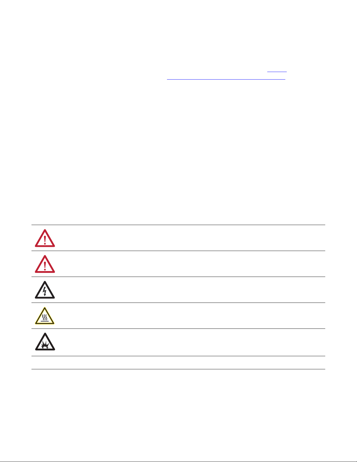
Throughout this manual, when necessary, we use notes to make you aware of safety considerations.
available from
) describes some
WARNING: Identifies information about practices or circumstances that can cause an explosion in a hazardous environment,
which may lead to personal injury or death, property damage, or economic loss.
ATTENTION: Identifies information about practices or circumstances that can lead to personal injury or death, property
damage, or economic loss. Attentions help you identify a hazard, avoid a hazard, and recognize the consequence.
SHOCK HAZARD: Labels may be on or inside the equipment, for example, a drive or motor, to alert people that dangerous
voltage may be present.
BURN HAZARD: Labels may be on or inside the equipment, for example, a drive or motor, to alert people that surfaces may
reach dangerous temperatures.
ARC FLASH HAZARD: Labels may be on or inside the equipment, for example, a motor control center, to alert people to
potential Arc Flash. Arc Flash will cause severe injury or death. Wear proper Personal Protective Equipment (PPE). Follow ALL
Regulatory requirements for safe work practices and for Personal Protective Equipment (PPE).
Identifies information that is critical for successful application and understanding of the product.
Allen-Bradley, Rockwell Automation, Rockwell Software, PowerFlex, Studio 5000, and Connected Components Workbench are trademarks of Rockwell Automation, Inc.
Trademarks not belonging to Rockwell Automation are property of their respective companies.
Page 3

Overview
Getting Started
Installing the Adapter
Table of Contents
Important User Information . . . . . . . . . . . . . . . . . . . . . . . . . . . . . . . . . . . . . . . 2
Preface
Recommended Documentation . . . . . . . . . . . . . . . . . . . . . . . . . . . . . . . . . . . . 7
Manual Conventions . . . . . . . . . . . . . . . . . . . . . . . . . . . . . . . . . . . . . . . . . . . . . . 7
Chapter 1
Components. . . . . . . . . . . . . . . . . . . . . . . . . . . . . . . . . . . . . . . . . . . . . . . . . . . . . . 9
Features . . . . . . . . . . . . . . . . . . . . . . . . . . . . . . . . . . . . . . . . . . . . . . . . . . . . . . . . . 10
Understanding Parameter Types. . . . . . . . . . . . . . . . . . . . . . . . . . . . . . . . . . . 10
Compatible Products . . . . . . . . . . . . . . . . . . . . . . . . . . . . . . . . . . . . . . . . . . . . . 11
Required Equipment . . . . . . . . . . . . . . . . . . . . . . . . . . . . . . . . . . . . . . . . . . . . . 11
Safety Precautions . . . . . . . . . . . . . . . . . . . . . . . . . . . . . . . . . . . . . . . . . . . . . . . . 12
Quick Start . . . . . . . . . . . . . . . . . . . . . . . . . . . . . . . . . . . . . . . . . . . . . . . . . . . . . . 13
Chapter 2
Preparing for Set-Up . . . . . . . . . . . . . . . . . . . . . . . . . . . . . . . . . . . . . . . . . . . . . 15
Setting the Node Address . . . . . . . . . . . . . . . . . . . . . . . . . . . . . . . . . . . . . . . . . 16
Connecting the Adapter to the Drive . . . . . . . . . . . . . . . . . . . . . . . . . . . . . . 18
Connecting the Adapter to the Network . . . . . . . . . . . . . . . . . . . . . . . . . . . 20
Applying Power . . . . . . . . . . . . . . . . . . . . . . . . . . . . . . . . . . . . . . . . . . . . . . . . . . 22
Commissioning the Adapter . . . . . . . . . . . . . . . . . . . . . . . . . . . . . . . . . . . . . . 24
Configuring the Adapter
Configuring the I/O
Chapter 3
Configuration Tools. . . . . . . . . . . . . . . . . . . . . . . . . . . . . . . . . . . . . . . . . . . . . . 25
Using the Drive Keypad Interface to Access Parameters . . . . . . . . . . . . . 25
Using the PowerFlex 4-Class HIM to Access Parameters. . . . . . . . . . . . . 27
Setting the Adapter Node Address. . . . . . . . . . . . . . . . . . . . . . . . . . . . . . . . . 27
Using a BOOTP or DHCP Server. . . . . . . . . . . . . . . . . . . . . . . . . . . . . . . . . 28
Using Adapter Parameters . . . . . . . . . . . . . . . . . . . . . . . . . . . . . . . . . . . . . . . . 31
Setting the Data Rate . . . . . . . . . . . . . . . . . . . . . . . . . . . . . . . . . . . . . . . . . . . . . 32
Using Master-Slave Hierarchy . . . . . . . . . . . . . . . . . . . . . . . . . . . . . . . . . . . . . 33
Setting a Fault Action . . . . . . . . . . . . . . . . . . . . . . . . . . . . . . . . . . . . . . . . . . . . 34
Resetting the Adapter . . . . . . . . . . . . . . . . . . . . . . . . . . . . . . . . . . . . . . . . . . . . 36
Restoring Adapter Parameters to Factory Defaults . . . . . . . . . . . . . . . . . . 36
Viewing the Adapter Status Using Parameters . . . . . . . . . . . . . . . . . . . . . . 37
Updating the Adapter Firmware. . . . . . . . . . . . . . . . . . . . . . . . . . . . . . . . . . . 37
Chapter 4
Using RSLinx Classic . . . . . . . . . . . . . . . . . . . . . . . . . . . . . . . . . . . . . . . . . . . . . 39
CompactLogix Example . . . . . . . . . . . . . . . . . . . . . . . . . . . . . . . . . . . . . . . . . . 40
Limitations in Using MicroLogix 1100/1400 . . . . . . . . . . . . . . . . . . . . . . . 62
Rockwell Automation Publication 520COM-UM003A-EN-E - June 2013 3
Page 4

Table of Contents
Chapter 5
Using the I/O
Using Explicit Messaging
Using Multi-Drive Mode
About I/O Messaging . . . . . . . . . . . . . . . . . . . . . . . . . . . . . . . . . . . . . . . . . . . . 63
Understanding the I/O Image. . . . . . . . . . . . . . . . . . . . . . . . . . . . . . . . . . . . . 64
Using Logic Command/Status . . . . . . . . . . . . . . . . . . . . . . . . . . . . . . . . . . . . 65
Using Reference/Feedback . . . . . . . . . . . . . . . . . . . . . . . . . . . . . . . . . . . . . . . . 65
Using Datalinks . . . . . . . . . . . . . . . . . . . . . . . . . . . . . . . . . . . . . . . . . . . . . . . . . . 66
Example Ladder Logic Program Information . . . . . . . . . . . . . . . . . . . . . . . 67
CompactLogix Example . . . . . . . . . . . . . . . . . . . . . . . . . . . . . . . . . . . . . . . . . . 67
Chapter 6
About Explicit Messaging . . . . . . . . . . . . . . . . . . . . . . . . . . . . . . . . . . . . . . . . . 73
Performing Explicit Messaging . . . . . . . . . . . . . . . . . . . . . . . . . . . . . . . . . . . . 74
CompactLogix Controller Examples . . . . . . . . . . . . . . . . . . . . . . . . . . . . . . . 74
Chapter 7
Single-Drive Mode vs. Multi-Drive Mode . . . . . . . . . . . . . . . . . . . . . . . . . . 87
System Wiring . . . . . . . . . . . . . . . . . . . . . . . . . . . . . . . . . . . . . . . . . . . . . . . . . . . 89
Understanding the I/O Image. . . . . . . . . . . . . . . . . . . . . . . . . . . . . . . . . . . . . 90
Configuring the RS-485 Network . . . . . . . . . . . . . . . . . . . . . . . . . . . . . . . . . 91
Using Multi-Drive Add-On Profile . . . . . . . . . . . . . . . . . . . . . . . . . . . . . . . . 91
Multi-Drive Ladder Logic Program for Generic Profile . . . . . . . . . . . . . 102
CompactLogix Controller Example Using Generic Profile . . . . . . . . . . 103
Multi-Drive Mode Explicit Messaging . . . . . . . . . . . . . . . . . . . . . . . . . . . . 111
Additional Information. . . . . . . . . . . . . . . . . . . . . . . . . . . . . . . . . . . . . . . . . . 112
Troubleshooting
Specifications
Adapter Parameters
Chapter 8
Understanding the Status Indicators . . . . . . . . . . . . . . . . . . . . . . . . . . . . . . 115
PORT Status Indicator . . . . . . . . . . . . . . . . . . . . . . . . . . . . . . . . . . . . . . . . . . 116
MOD Status Indicator. . . . . . . . . . . . . . . . . . . . . . . . . . . . . . . . . . . . . . . . . . . 116
NET A Status Indicator . . . . . . . . . . . . . . . . . . . . . . . . . . . . . . . . . . . . . . . . . 116
NET B Status Indicator. . . . . . . . . . . . . . . . . . . . . . . . . . . . . . . . . . . . . . . . . . 117
Viewing Adapter Diagnostic Items. . . . . . . . . . . . . . . . . . . . . . . . . . . . . . . . 117
Viewing and Clearing Events . . . . . . . . . . . . . . . . . . . . . . . . . . . . . . . . . . . . . 120
Appendix A
Communication . . . . . . . . . . . . . . . . . . . . . . . . . . . . . . . . . . . . . . . . . . . . . . . . 123
Electrical . . . . . . . . . . . . . . . . . . . . . . . . . . . . . . . . . . . . . . . . . . . . . . . . . . . . . . . 123
Mechanical . . . . . . . . . . . . . . . . . . . . . . . . . . . . . . . . . . . . . . . . . . . . . . . . . . . . . 123
Environmental . . . . . . . . . . . . . . . . . . . . . . . . . . . . . . . . . . . . . . . . . . . . . . . . . . 123
Regulatory Compliance. . . . . . . . . . . . . . . . . . . . . . . . . . . . . . . . . . . . . . . . . . 123
Appendix B
Device Parameters . . . . . . . . . . . . . . . . . . . . . . . . . . . . . . . . . . . . . . . . . . . . . . . 125
4 Rockwell Automation Publication 520COM-UM003A-EN-E - June 2013
Page 5

Appendix C
Table of Contents
EtherNet/IP Objects
Logic Command/Status Words:
PowerFlex 525 Drives
Supported Data Types . . . . . . . . . . . . . . . . . . . . . . . . . . . . . . . . . . . . . . . . . . . 129
Identity Object. . . . . . . . . . . . . . . . . . . . . . . . . . . . . . . . . . . . . . . . . . . . . . . . . . 130
Assembly Object . . . . . . . . . . . . . . . . . . . . . . . . . . . . . . . . . . . . . . . . . . . . . . . . 132
Register Object. . . . . . . . . . . . . . . . . . . . . . . . . . . . . . . . . . . . . . . . . . . . . . . . . . 133
Parameter Object . . . . . . . . . . . . . . . . . . . . . . . . . . . . . . . . . . . . . . . . . . . . . . . 136
PCCC Object . . . . . . . . . . . . . . . . . . . . . . . . . . . . . . . . . . . . . . . . . . . . . . . . . . 139
DPI Device Object . . . . . . . . . . . . . . . . . . . . . . . . . . . . . . . . . . . . . . . . . . . . . . 142
DPI Parameter Object . . . . . . . . . . . . . . . . . . . . . . . . . . . . . . . . . . . . . . . . . . . 145
DPI Fault Object. . . . . . . . . . . . . . . . . . . . . . . . . . . . . . . . . . . . . . . . . . . . . . . . 151
TCP/IP Interface Object . . . . . . . . . . . . . . . . . . . . . . . . . . . . . . . . . . . . . . . . 153
Ethernet Link Object. . . . . . . . . . . . . . . . . . . . . . . . . . . . . . . . . . . . . . . . . . . . 155
Appendix D
Logic Command Word . . . . . . . . . . . . . . . . . . . . . . . . . . . . . . . . . . . . . . . . . . 157
Logic Status Word . . . . . . . . . . . . . . . . . . . . . . . . . . . . . . . . . . . . . . . . . . . . . . 158
Glossary
Index
Rockwell Automation Publication 520COM-UM003A-EN-E - June 2013 5
Page 6

Table of Contents
Notes:
6 Rockwell Automation Publication 520COM-UM003A-EN-E - June 2013
Page 7

Preface
Overview
This manual provides information about the Dual-port EtherNet/IP adapter and
using it with PowerFlex 520-series drives for network communication.
For information on… See page…
Recommended Documentation
Manual Conventions 7
7
Recommended Documentation
All the recommended documentation listed in this section is available online at
http://www.rockwellautomation.com/literature
.
The following publications provide additional information:
For... See... Publication
EtherNet/IP™ EtherNet/IP Media Planning and Installation Manual
EtherNet/IP Network Infrastructure Guidelines
EtherNet/IP Network Configuration User Manual ENET-UM001
Troubleshoot EtherNet/IP Networks ENET-AT003
EtherNet/IP Design, Commissioning, and
Troubleshooting Quick Reference Drawings
Ethernet Design Considerations Reference Manual ENET-RM002
PowerFlex®520-Series Drives PowerFlex 525 Adjustable Frequency AC Drive User Manual 520-UM001
PowerFlex 520-Series Communication Adapters Installation
Instructions
HIM (Human Interface Module) PowerFlex 4-Class HIM (DSI) Quick Reference 22HIM-QR001
RSLinx® Classic RSLinx Classic Getting Results Guide
RSLogix™ 5000 RSLogix 5000 online help
CompactLogix™ 5370 CompactLogix 5370 Controllers User Manual (1769-L36ERM) 1769-UM021
MicroLogix™ 1100 MicroLogix 1100 Programmable Controllers User Manual 1763-UM001
MicroLogix™ 1400 MicroLogix 1400 Programmable Controllers User Manual 1766-UM001
(1) For ODVA publications, see the ODVA Ethernet/IP library at
http://odva.org/Home/ODVATECHNOLOGIES/EtherNetIP/EtherNetIPLibrary/tabid/76/lng/en-US/Default.aspx
(2) The online help is installed with the software.
(2)
(2)
(1)
(1)
ODVA Pub. 148
ODVA Pub. 35
IASIMP-QR023
520COM-IN001
LINX-GR001
–
Manual Conventions
The following conventions are used throughout this manual:
• Parameter names are shown in the format Device parameter xx [*] or Host
parameter axxx [*]. The xx/xxx represents the parameter number and the a
represents the parameter group. The * represents the parameter name— for
example Device parameter 01 [MultiDrv Sel].
• Menu commands are shown in bold type face and follow the format Menu
> Command. For example, if you read “Select File > Open,” yo u s ho ul d
click the File menu and then click the Open command.
Rockwell Automation Publication 520COM-UM003A-EN-E - June 2013 7
Page 8

Preface Overview
• The Studio 5000™ Engineering and Design Environment combines
engineering and design elements into a common environment. The first
element in the Studio 5000 environment is the Logix Designer
application. The Logix Designer application is the rebranding of
RSLogix 5000 software and will continue to be the product to program
Logix 5000 controllers for discrete, process, batch, motion, safety, and
drive-based solutions. The Studio 5000 environment is the foundation for
the future of Rockwell Automation engineering design tools and
capabilities. It is the one place for design engineers to develop all the
elements of their control system.
• RSLogix 5000 software (version 20) was used for the screen captures in
this manual. Different versions of the software may differ in appearance
and procedures.
• The PowerFlex 520-series Adjustable Frequency AC Drive consists of
PowerFlex 525 (used in the examples throughout this manual) and
PowerFlex 523.
8 Rockwell Automation Publication 520COM-UM003A-EN-E - June 2013
Page 9
Chapter 1
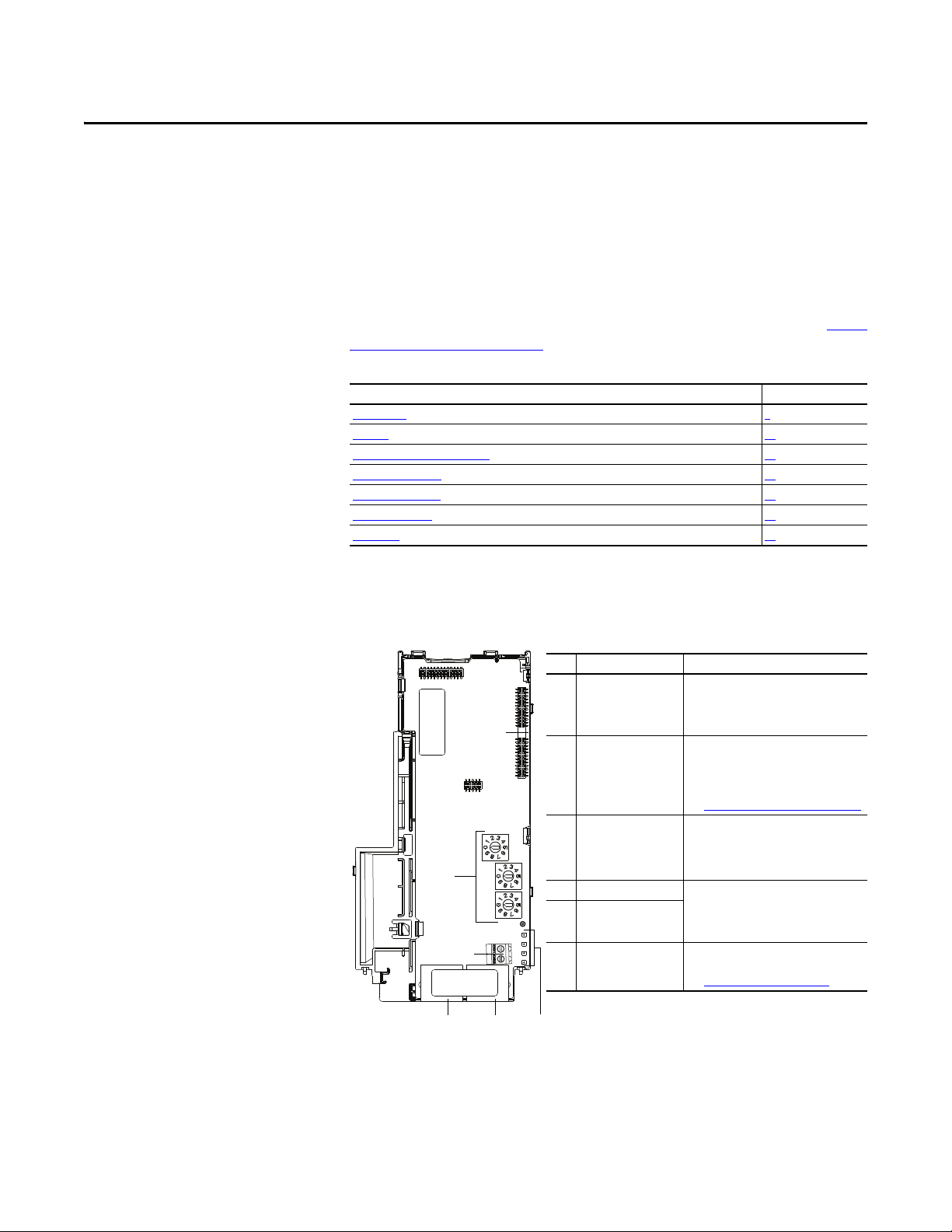
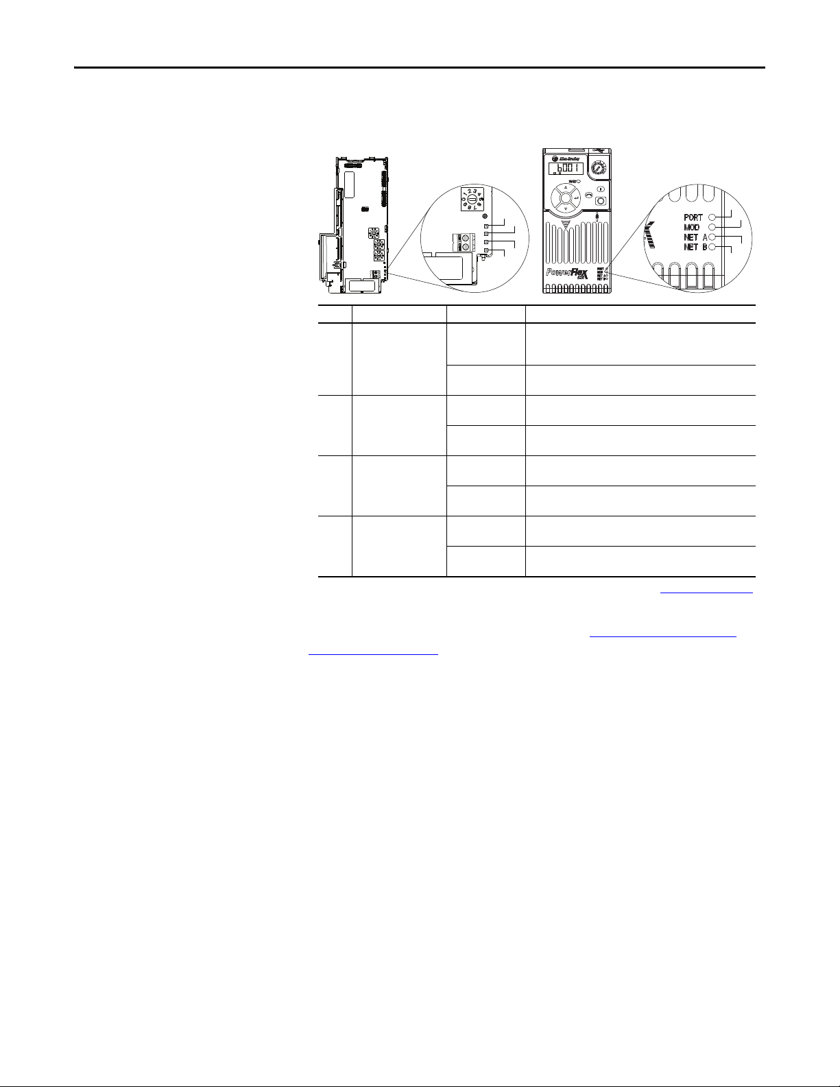
Item Part Description
➊ Communication
card-Drive header
A 40-pin, double-row shrouded female
header. An interface connector is used to
connect this header to a header on the
drive.
➋ Node Address switches Sets the network node address of the
adapter when not using:
• A BOOTP or DHCP server
• Adapter parameters
See Setting the Node Address
on page 16.
➌ CS1/CS2 terminals Provides a clean ground for the
communication bus cable shields.
CS1 or CS2 should be connected to a clean
ground or PE ground on the drive.
➍ ENET1 Network por t An RJ-45 connector for the Ethernet
cable. It is CAT-5 compliant to ensure
reliable data transfer on 100Base-Tx
Ethernet connections.
➎ ENET2 Network port
➏ Status indicators Four LEDs that indicate the status of the
connected drive, adapter and network.
See Troubleshooting
on page 115.
25-COMM-E2P
➊
➋
➌
➍
➎ ➏
Getting Started
The Dual-port EtherNet/IP adapter is a communication option intended for
installation into a PowerFlex 520-series drive. The Multi-Drive feature (see Usi ng
Multi-Drive Mode on page 87) also provides a means for other supported
PowerFlex drives and DSI Hosts to connect to an EtherNet/IP network.
Top ic Pa ge
Components 9
Feature s 10
Understanding Parameter Types 10
Compatible Products 11
Required Equipment 11
Safety Precautions 12
Quick Start 13
Components
Components of the Dual-Port EtherNet/IP Adapter
Rockwell Automation Publication 520COM-UM003A-EN-E - June 2013 9
Page 10

Chapter 1 Getting Started
Features
The features of the Dual-port EtherNet/IP adapter include:
• Industrial Ethernet switch, and ENET1 and ENET2 network ports that
provide connections for EtherNet/IP star, linear, or device-level ring
(DLR) network topologies.
• Switches to set a network node address before applying power to the
drive—or you can disable the switches and use a BOOTP server, a
Dynamic Host Configuration Protocol (DHCP) server, or adapter
parameters to configure the IP address.
• Compatibility with various configuration tools to configure the adapter
and host drive. The tools include the PowerFlex 4/40-class HIM (Human
Interface Module 22-HIM-A3 or 22-HIM-C2S), and drive-configuration
software such as RSLogix 5000 (version 17 or greater), Logix Designer
(version 21 or greater), and Connected Components Workbench (version
3 or greater).
• Status indicators that report the status of the adapter and network
communications.
• Parameter-configured 16-bit Datalinks in the I/O to meet application
requirements (four Datalinks to write data from the network to the drive,
and four Datalinks to read data to the network from the drive).
• Explicit Messaging support.
• Master-Slave hierarchy that can be configured to transmit data to and from
a controller on the network.
• Multi-drive mode which allows up to five drives to share a single
EtherNet/IP node.
• User-defined fault actions to determine how the adapter and its host
PowerFlex 520-series drive respond to:
– I/O messaging communication disruptions (Comm Flt Action)
– Controllers in idle mode (Idle Flt Action)
• Automatic Device Configuration (ADC) is an RSLogix 5000 (version 20
or greater) and Logix Designer (version 21 or greater) software feature that
supports the automatic download of configuration data upon the Logix
controller establishing an EtherNet/IP network connection to a
PowerFlex 520-series drive and its associated peripherals.
Understanding Parameter Types
10 Rockwell Automation Publication 520COM-UM003A-EN-E - June 2013
This manual references two types of parameters:
• Device parameters are used to configure the adapter to operate on the
network. These parameters reside on the adapter.
• Host parameters are used to configure the drive, including the datalink
configuration for the datalinks used by the adapter. These parameters
reside on the drive.
Page 11

Getting Started Chapter 1
Yo u c an vi ew ad ap te r Device parameters and Host parameters with any of the
following drive configuration tools:
• PowerFlex 4-class HIM (22-HIM-A3 or 22-HIM-C2S)
• Connected Components Workbench software – click the tab for the
adapter at the bottom of the window, and click the Parameters icon in the
tool bar.
Compatible Products
Required Equipment
At the time of publication, the adapter is compatible with Allen-Bradley
PowerFlex 525 and PowerFlex 523 drives.
Equipment Shipped with the Drive
When you unpack the adapter, verify that the package includes:
❑ One PowerFlex 520-series Dual-port EtherNet/IP communications adapter (25-COMM-E2P)
(installed in a PowerFlex 520-series drive control module back cover)
❑ Two interface connectors (for connecting the Communication card-Drive header to the header on the drive)
❑ One PowerFlex 520-series Communication Adapters Installation Instructions, publication 520COM-IN001
User-Supplied Equipment
The adapter parameters can be configured using the drive keypad interface (see
Using the Drive Keypad Interface to Access Parameters
you must supply:
❑ Ethernet cable (see the EtherNet/IP Media Planning and Installation Manual, ODVA publication 148 available on the
ODVA web site at http://odva.org/Home/ODVATECHNOLOGIES/EtherNetIP/EtherNetIPLibrary/tabid/76/Default.aspx
for details)
❑ Ethernet switch (see the Ethernet Design Considerations Reference Manual, Rockwell Automation publication
ENET-RM002
❑ Optional configuration tool, such as:
– PowerFlex 22-HIM-A3/-C2S HIM
– DHCP/BOOTP Utilities
❑ Controller configuration software, such as:
– RSLinx Classic (version 2.50 or later)
– RSLogix 5000 (version 17 or greater) or Logix Designer (version 21 or greater) when using drive-specific Add-On
– Connected Components Workbench (version 3 or greater)
❑ A PC connection to the EtherNet/IP network
for details)
Profile (AOP)
on page 25). In addition,
Rockwell Automation Publication 520COM-UM003A-EN-E - June 2013 11
Page 12

Chapter 1 Getting Started
Safety Precautions
Please read the following safety precautions carefully.
ATT EN TI ON : Risk of injury or death exists. The PowerFlex drive may contain
high voltages that can cause injury or death. Remove all power from the
PowerFlex drive, and then verify power has been removed before installing or
removing an adapter.
ATT EN TI ON : Risk of injury or equipment damage exists. Only personnel
familiar with drive and power products and the associated machinery should
plan or implement the installation, start up, configuration, and subsequent
maintenance of the drive using this Dual-port EtherNet/IP adapter. Failure to
comply may result in injury and/or equipment damage.
ATT EN TI ON : Risk of equipment damage exists. The adapter contains ESD
(Electrostatic Discharge) sensitive parts that can be damaged if you do not
follow ESD control procedures. Static control precautions are required when
handling the adapter. If you are unfamiliar with static control procedures, see
Guarding Against Electrostatic Damage, publication 8000-4.5.2
ATT EN TI ON : Risk of injury or equipment damage exists. If the adapter is
transmitting control I/O to the drive, the drive may fault when you reset the
adapter. Determine how your drive will respond before resetting the adapter.
ATT EN TI ON : Risk of injury or equipment damage exists. Device parameters 23
[Comm Flt Action] and 24 [Idle Flt Action] let you determine the action of
the adapter and drive if I/O communication is disrupted, the controller is idle, or
explicit messaging for drive control is disrupted. By default, these parameters
fault the drive. You may configure these parameters so that the drive continues
to run, however, precautions should be taken to ensure that the settings of
these parameters do not create a risk of injury or equipment damage. When
commissioning the drive, verify that your system responds correctly to various
situations (for example, a disconnected cable or a controller in idle state).
ATT EN TI ON : Risk of injury or equipment damage exists. When a system is
configured for the first time, there may be unintended or incorrect machine
motion. Disconnect the motor from the machine or process during initial system
testing.
ATT EN TI ON : Risk of injury or equipment damage exists. The examples in this
publication are intended solely for purposes of example. There are many
variables and requirements with any application. Rockwell Automation, Inc.
does not assume responsibility or liability (to include intellectual property
liability) for actual use of the examples shown in this publication.
.
12 Rockwell Automation Publication 520COM-UM003A-EN-E - June 2013
Page 13
Getting Started Chapter 1
Quick Start
This section is provided to help experienced users quickly start using the adapter.
If you are unsure how to complete a step, refer to the referenced chapter.
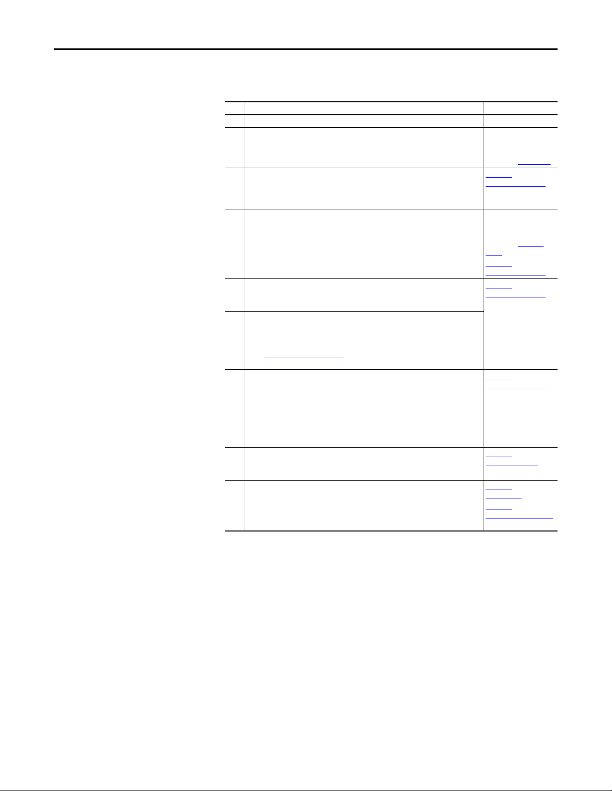
Step Action See...
1 Review the safety precautions for the adapter. Throughout this manual
2 Verify that the PowerFlex drive is properly installed. PowerFlex 525
3 Commission the adapter.
Set the adapter IP address. When using the adapter node address switches, set the IP
address now and proceed with step 4. When using a DHCP or BOOTP server, or adapter
parameters instead to set the IP address, proceed with step 4.
4 Install the adapter.
Verify that the PowerFlex drive is not powered. Then, connect the adapter to the drive
using the interface connector (included with adapter).
5 Connect the adapter to the EtherNet/IP network.
Verify that the PowerFlex drive is not powered. Then, connect the adapter to the
network using an Ethernet cable.
6 Apply power to the drive.
a. Replace the control module cover.
b. The adapter receives power from the drive. Apply power to the drive. The status
indicators should be green. If they flash red, there is a problem. See
Troubleshooting on page 115.
c. Configure and verify key drive parameters.
7 Configure the adapter for your application.
Set adapter parameters for the following functions as required by your application:
– IP address, subnet mask, and gateway address (only when not using adapter
node address switches)
– Data rate
– I/O configuration
– Master-Slave hierarchy
– Fault actions
8 Configure the controller to communicate with the adapter.
Use a control ler configuration too l such as RSLogix 500 0 or Logix Designer to configure
the master on the EtherNet/IP network to recognize the adapter and drive.
9 Create a ladder logic program.
Use a controller configuration tool such as RSLogix 5000 or Logix Designer to create a
ladder logic program that enables you to:
– Control the adapter and connected drive using I/O.
– Monitor or configure the drive using Explicit messages.
Adjustable Freq uency AC
Drive User Manual,
publication 520-UM001
Chapter 2,
Installing the Adapter
PowerFlex 520-Series
Communication Adap ters
Installation Instructions,
publication 520COM-
IN001 and
Chapter 2,
Installing the Adapter
Chapter 2,
Installing the Adapter
,
Chapter 3
Configuring the Adapter
Chapter 4,
Configuring the I/O
Chapter 5,
Using the I/O
Chapter 6,
Using Explicit Messaging
Rockwell Automation Publication 520COM-UM003A-EN-E - June 2013 13
Page 14

Chapter 1 Getting Started
Notes:
14 Rockwell Automation Publication 520COM-UM003A-EN-E - June 2013
Page 15

Chapter 2
Installing the Adapter
Chapter 2 provides instructions for installing the Dual-port EtherNet/IP adapter
in a PowerFlex 520-series drive.
Top ic Pa ge
Preparing for Set-Up
Setting the Node Address 16
Connecting the Ad apter to the Drive 18
Connecting the Adapter to the Network 20
Applying Power 22
Commissioning the Adapter 24
15
Preparing for Set-Up
Before installing the adapter, do the following:
• Make sure the Ethernet switch is the correct type. A “managed” switch that
supports IGMP snooping is usually recommended. An “unmanaged”
switch can be used instead if RSLogix 5000 software (version 18 or
greater) is used and all devices on the network are configured for “unicast”
I/O. For more details, see the following documents:
– EtherNet/IP Media Planning and Installation Manual,
ODVA publication 148
– EtherNet/IP Network Infrastructure Guidelines,
ODVA publication 35
– Ethernet Design Considerations Reference Manual,
publication ENET-RM002
• Understand IGMP Snooping/Ethernet Switches
The adapter is a multicast device. In most situations, an IGMP snooping
(managed) switch is required. If more than one or two adapters are
connected to the switch, a managed switch is required—otherwise the
drive may fault on a Net I/O Timeout network loss. The adapter,
RSLogix 5000 (version 18 or greater), Logix Designer (version 21 or
greater), and a ControlLogix or CompactLogix controller will support
unicast. Unicast setup is required when adding the drive to the I/O. When
all adapters are set up as unicast devices, then an IGMP snooping
(managed) switch is not needed.
Much of EtherNet/IP implicit (I/O) messaging uses IP multicast to
distribute I/O control data, which is consistent with the CIP producer/
consumer model. Historically, most switches have treated multicast
packets the same as broadcast packets. That is, all multicast packets are retransmitted to all ports.
Rockwell Automation Publication 520COM-UM003A-EN-E - June 2013 15
Page 16

Chapter 2 Installing the Adapter
IMPORTANT
IGMP snooping constrains the flooding of multicast traffic by dynamically
configuring switch ports so that multicast traffic is forwarded only to ports
associated with a particular IP multicast group.
Switches that support IGMP snooping (managed switches) “learn” which
ports have devices that are part of a particular multicast group and only
forward the multicast packets to the ports that are part of the multicast
group.
Be careful as to what level of support a switch has of IGMP snooping.
Some layer 2 switches that support IGMP snooping require a router
(which could be a layer 3 switch) to send out IGMP polls to learn what
devices are part of the multicast group. Some layer 2 switches can use
IGMP snooping without a router sending polls. If your control system is a
stand-alone network or is required to continue performing if the router is
out of service, make sure the switch you are using supports IGMP
snooping without a router being present.
• See Specifications
on page 123 for the number of CIP connections
supported by the adapter.
• Verify that you have all required equipment. See Required Equipment
page 11.
on
Setting the Node Address
ATT EN TI ON : Risk of equipment damage exists. The adapter contains ESD
(Electrostatic Discharge) sensitive parts that can be damaged if you do not
follow ESD control procedures. Static control precautions are required when
handling the adapter. If you are unfamiliar with static control procedures, see
Guarding Against Electrostatic Damage, publication 8000-4.5.2
.
The adapter has EtherNet/IP embedded switch technology, and ENET1 and
ENET2 network ports to connect to a linear or device-level ring (DLR) network
in a single subnet.
You cannot use ENET1 and ENET 2 network ports as two network interface
cards connected to two different subnets.
There are four methods for configuring the adapter’s node address:
• Node Address Switches — Use these switches when working on a simple
isolated network (for example, 192.168.1.xxx) that has other products
with switches to set their IP addresses, does not need to be accessed from
outside the network, and you prefer a simplified node addressing method.
The three rotary switches are read when the drive powers up, and represent
three decimal digits from top to bottom (see Setting the Node Address
Switches on page 18). When set to a valid address (001...254), the adapter
will use that value as the lower octet of its IP address (192.168.1.xxx, where
xxx = rotary switch settings), along with a subnet mask of 255.255.255.0,
and a gateway address of 0.0.0.0 when switches are set to 001, or a gateway
address of 192.168.1.1 when switches are set from 002...254. Also, the
setting for Device parameter 04 [Net Addr Sel] is automatically ignored.
16 Rockwell Automation Publication 520COM-UM003A-EN-E - June 2013
Page 17

Installing the Adapter Chapter 2
IMPORTANT
IMPORTANT
IMPORTANT
See Setting the Node Address Switches on page 18 and its accompanying
table for all possible switch settings and their related descriptions.
When using the Node Address switches, set the network node address
before power is applied because the adapter uses the node address it
detects when it first receives power.
•Adapter Parameters — Use adapter parameters when you want more
flexibility in setting up the IP address, or need to communicate outside the
control network using a gateway. To use parameters as the source for the IP
address, the Node Address switches must be set to a value other than
001...254 or 888, and Device parameter 04 [Net Addr Sel] must be set to
1“Parameters”. The IP address, subnet mask, and gateway addresses will
then come from the parameters you set. See Using Adapter Parameters
page 31for more information.
If parameter values are invalid or the adapter was not reset for the
values to take effect, the node address is established by using DHCP.
on
•BOOTP Server — Use BOOTP when you want to configure a temporary
IP address, subnet mask, and gateway address for the adapter using a
BOOTP server. To use BOOTP as the source for the IP address, the Node
Address switches must be set to a value other than 001...254 or 888, and
Device parameter 04 [Net Addr Sel] must be set to 2 “BOOTP”.
Note the adapter’s hardware Ethernet Address (MAC) on the adapter’s
data nameplate label located on the provided control module back cover,
which will be used in Step 7 when configuring the BOOTP server (see
Using a BOOTP or DHCP Ser ver
on page 28 for details).
• DHCP (Dynamic Host Configuration Protocol) — Use DHCP, the
default, when you want additional flexibility and ease-of-use compared to
BOOTP in configuring the IP address, subnet mask, and gateway address
for the adapter using a DHCP server. To use DHCP as the source for the
IP address, the Node Address switches must be set to a value other than
001…254 or 888, and Device parameter 04 [Net Addr Sel] must be set to 3
“DHCP”.
Note the adapter’s hardware Ethernet Address (MAC) on the adapter’s
data nameplate label located on the provided control module back cover,
which will be used in Step 7 when configuring the DHCP server (see
Using a BOOTP or DHCP Ser ver
on page 28 for details).
Regardless of the method used to set the adapter’s node address, each node on
the EtherNet/IP network must have a unique IP address. To change a node
address, you must set the new value and then remove and reapply power to (or
reset) the drive.
Rockwell Automation Publication 520COM-UM003A-EN-E - June 2013 17
Page 18
Chapter 2 Installing the Adapter
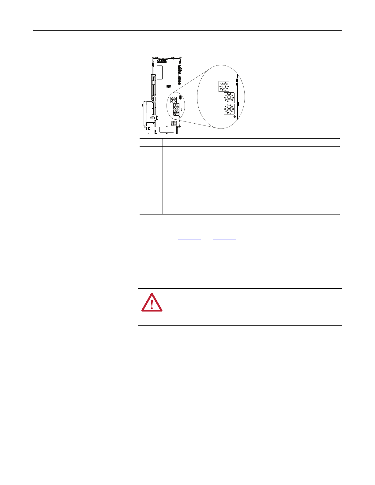
Hundreds
position
Ten s
position
Ones
position
Setting Description
001...254 The adapter will use the Node Address switch settings for the network node address (192.168.1.xxx,
where xxx = rotary switch settings). The value stored in Device parameter 04 [Net Addr Sel] is
automatically ignored.
888 Resets the adapter network node address to factory defaults. Thereafter, the drive must be powered
down, the Node Address switches must be set to a correct value (001…254), and then the drive must be
powered up again to accept the new address.
Any other
setting
Disables the Node Address switches, and requires using Device parameter 04 [Net Addr Sel] to select
the source for the adapter’s network node address:
• 1 = Parameters of the adapter
• 2 = BOOTP server
• 3 = DHCP server (Default)
Setting the Node Address Switches
Connecting the Adapter to the Drive
The Node Address switch settings can be verified by viewing Diagnostic Item
number 58 (see page 118
and page 120) with a PowerFlex 22-HIM-A3 or 22HIM-C2S HIM, or Connected Components Workbench (version 3 or greater)
software. Also, you can use Device parameter 05 [Net Addr Src], a read-only
parameter, to verify the selected setting for Device parameter 04 [Net Addr Sel].
ATT EN TI ON : Risk of injury or death exists. The PowerFlex drive may contain
high voltages that can cause injury or death. Remove all power from the
PowerFlex drive, and then verify power has been removed before installing or
removing an adapter.
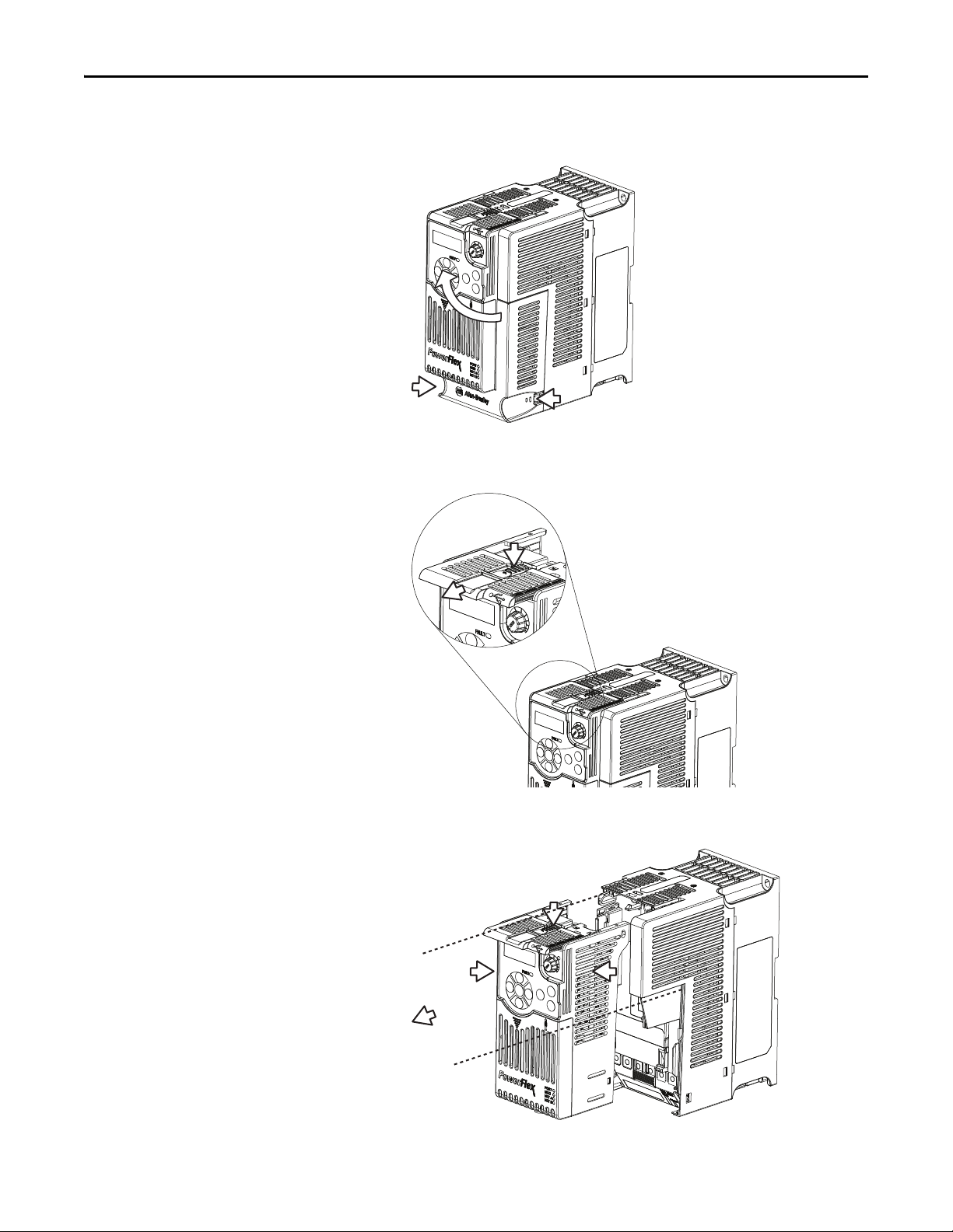
1. Remove power from the drive.
2. Use static control precautions.
3. Separate the drive’s control module from the power module.
18 Rockwell Automation Publication 520COM-UM003A-EN-E - June 2013
Page 19
Installing the Adapter Chapter 2
a. Press and hold down the catch on both sides of the frame cover, then
pullout and swing upwards to remove (Frames B...E only).
b. Press down and slide out the top cover of the control module to unlock
it from the power module.
c. Hold the sides and top of the control module firmly, then pull out to
separate it from the power module.
Rockwell Automation Publication 520COM-UM003A-EN-E - June 2013 19
Page 20
Chapter 2 Installing the Adapter
IMPORTANT
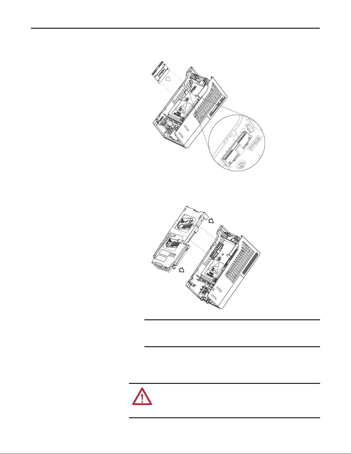
4. Insert the interface connector for the adapter into the header located at the
back of the control module.
5. Align the Communication card-Drive header on the adapter with the
interface connector. Then, press down firmly around the adapter. The
adapter snaps into the back of the control module.
The CS1/CS2 terminals on the adapter provide a clean ground for the
communication bus cable shields. You should connect the CS1 or CS2
terminal to a clean ground or PE ground on the drive.
6. Attach the control module to the power module.
Connecting the Adapter to the Network
20 Rockwell Automation Publication 520COM-UM003A-EN-E - June 2013
ATT EN TI ON : Risk of injury or death exists. The PowerFlex drive may contain
high voltages that can cause injur y or death. Remove power from the drive, and
then verify power has been discharged before connecting the adapter to the
network.
Page 21
Installing the Adapter Chapter 2
IMPORTANT
1 (Front)1 (Front)1 (Front)
2 (Rear)
00:00:BC:2E:69:F6
Esc
Sel
Esc
Sel
External
Ethernet
switch
1769-L36ERM CompactLogix controller
with embedded EtherNet/IP bridge
PowerFlex 520-series drives with
25-COMM-E2P adapter
(1)
(Frame A shown)
Computer with
Ethernet Connection
To o ther
EtherNet/IP
networks
(1) The Ethernet cable may be connected to the adapter’s ENET1 or ENET 2 network port.
1 (Front)1 (Front)1 (Front)
2 (Rear)
00:00:BC:2E:69:F6
Esc
Sel
Esc
Sel
External
Ethernet
switch
1769-L36ERM CompactLogix controller
with embedded EtherNet/IP bridge
PowerFlex 520-series drives with
25-COMM-E2P adapter
(1)
(Frame A shown)
Computer with
Ethernet Connection
To o ther
EtherNet/IP
networks
(1) The adapter’s ENET1 and ENET2 network ports are used.
1. Remove power from the drive.
2. Use static control precautions.
3. Connect one end of an Ethernet cable to the network.
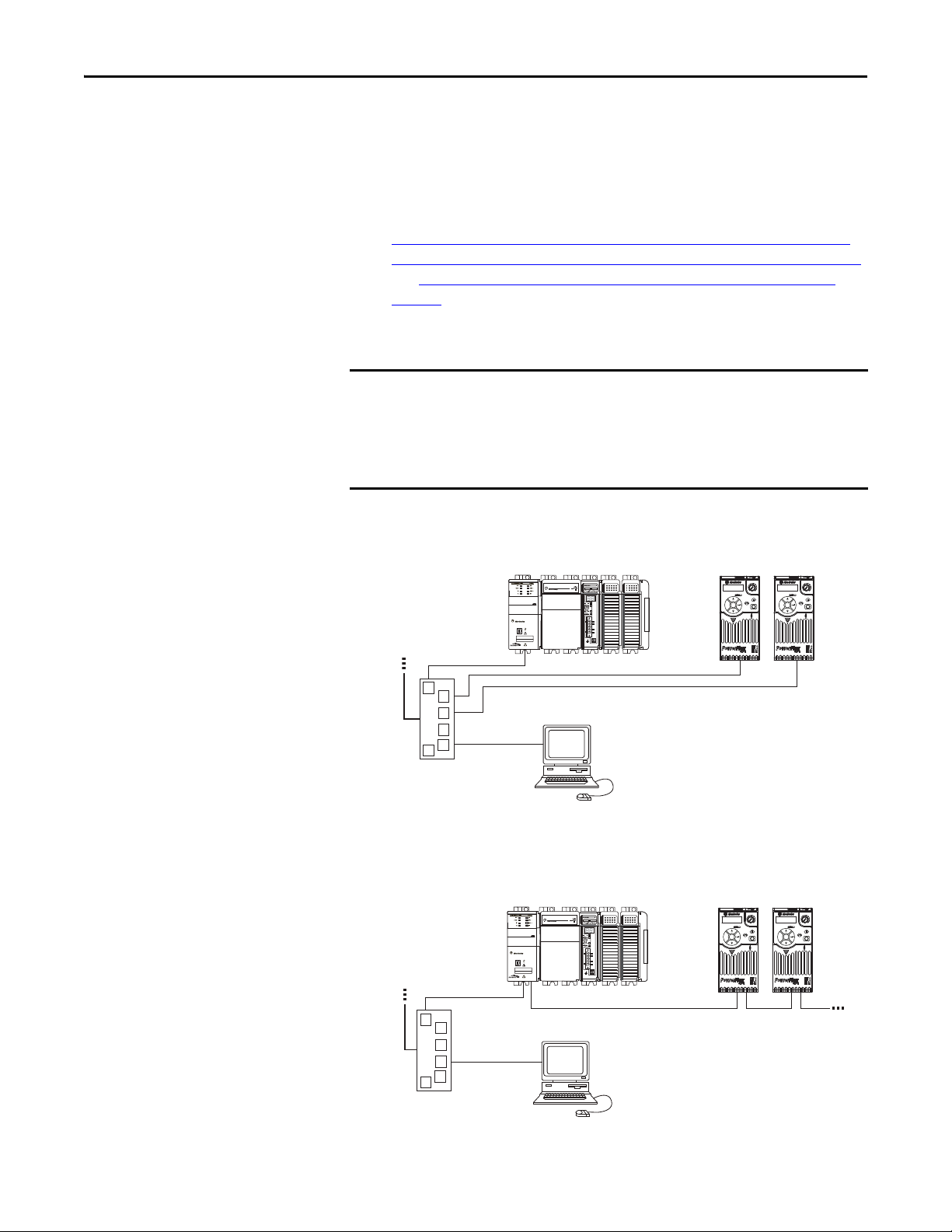
Examples of different EtherNet/IP network topologies are shown in
Connecting the Ethernet Cable in a Star Topology Network
Connecting the Ethernet Cable in a Linear Topology Network
on page 21,
on page 21,
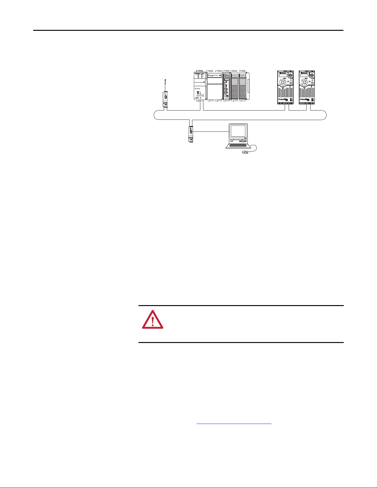
and Connecting the Ethernet Cable in a DLR Topology Network
page 22. For information about linear and device-level ring (DLR)
topologies, see EtherNet/IP Embedded Switch Technology, publication
ENET-AP005.
The adapter has EtherNet/IP embedded switch technology, and ENET1 and
ENET2 network ports to connect to a linear or device-level ring (DLR) network
in a single subnet.
You cannot use ENET1 and ENET 2 network ports as two network interface
cards connected to two different subnets.
on
Connecting the Ethernet Cable in a Star Topology Network
Connecting the Ethernet Cable in a Linear Topology Network
Rockwell Automation Publication 520COM-UM003A-EN-E - June 2013 21
Page 22
Chapter 2 Installing the Adapter
1 (Front)1 (Front)1 (Front)
2 (Rear)
00:00:BC:2E:69:F6
Esc
Sel
Esc
Sel
1783-ETAP
1769-L36ERM CompactLogix controller
with embedded EtherNet/IP bridge
PowerFlex 520-series drives with
25-COMM-E2P adapter
(1)
(Frame A shown)
Computer with
Ethernet Connection
To o ther
EtherNet/IP
networks
(1) The adapter’s ENET1 and ENET2 network ports are used.
1783-ETAP
Connecting the Ethernet Cable in a DLR Topology Network
4. Depending on the network topology, do one of the following:
• Star Network Topology—Route the other end of the Ethernet cable
from the network through the bottom of the drive, and insert its cable
plug into the option module’s ENET1 or ENET2 network port.
• Linear or DLR Network Topology—Route the other end of the
Ethernet cable from the network through the bottom of the first drive,
and insert its cable plug into the option module ENET1 network port.
Applying Power
To connect to the second drive, attach another Ethernet cable between
the first drive’s option module ENET2 network port and the second
drive’s option module ENET1 network port.
To connect additional drives, repeat these daisy-chain connections in
the same way.
ATT EN TI ON : Risk of equipment damage, injury, or death exists. Unpredictable
operation may occur if you fail to verify that parameter settings are compatible
with your application. Verify that settings are compatible with your application
before applying power to the drive.
Apply power to the drive. The adapter receives its power from the drive.
Startup Status Indication
After power has been applied, the status indicators can be viewed on the front of
the drive. When you apply power to the adapter for the first time, the status
indicators should be green after an initialization. If the status indicators go red,
there is a problem. See Troubleshooting
on page 115.
22 Rockwell Automation Publication 520COM-UM003A-EN-E - June 2013
Page 23
Drive and Adapter Status Indicators
Esc
Sel
➊
➋
➌
25-COMM-E2P PowerFlex 525 Frame A shown
➍
➊
➋
➌
➍
Item Status Indicator Status
(1)
(1) If all status indicators are off, the adapter is not receiving power. If any other conditions occur, see Troubleshooting on page 85.
Description
➊ PORT Flashing green Normal operation. The adapter is establishing an I/O
connection to the drive. This status indicator will turn
steady green or red.
Steady green Normal operation. The adapter is properly connected and is
communicating with the drive.
➋ MOD Flashing green Normal operation. The adapter is operating but is not
transferring I/O data to a controller.
Steady green Normal operation. The adapter is operating and transferring
I/O data to a controller.
➌ NET A Flashing green Normal operation. The adapter is properly connected but is
not communicating with any devices on the network.
Steady green Normal operation. The adapter is properly connected and
communicating on the network to a controller.
➍ NET B Off Normal operation. The adapter is properly connected, but is
idle.
Flashing green Normal operation. The adapter is properly connected and
transmitting on the network.
Installing the Adapter Chapter 2
FWD
ENET LINK
EtherNet/IP
For more details on status indicator operation see Understanding the Status
Indicators on page 115.
Configuring/Verifying Key Drive Parameters
The PowerFlex 525 drive can be separately configured for the control and
Reference functions in various combinations. For example, you could set the
drive to have its control come from a peripheral or terminal block with the
Reference coming from the network. Or you could set the drive to have its
control come from the network with the Reference coming from another
peripheral or terminal block. Or you could set the drive to have both its control
and Reference come from the network.
Configuring the Host parameters can be done using the drive’s keypad, a HIM,
and software such as RSLogix 5000 or Logix Designer, or Connected
Components Workbench. In the following example, the drive will receive the
Logic Command and Reference from the network.
1. Set the value of Host parameter P046 [Start Source 1]
to 4 “Network Opt”.
Rockwell Automation Publication 520COM-UM003A-EN-E - June 2013 23
Page 24

Chapter 2 Installing the Adapter
TIP
IMPORTANT
2. Set the value of Host parameter P047 [Speed Reference1]
to 4 “Network Opt”.
The PowerFlex 525 drive supports up to three control functions and
three Reference functions.
For more information on how to set different combinations of the control and
Reference functions, see the PowerFlex 525 drive user manual,
publication 520-UM001
.
Commissioning the Adapter
To commission the adapter, you must set a unique network node address. See the
Glossary
Address switches, see Setting the Node Address
using these switches, a BOOTP or DHCP server, or adapter parameters can be
used to set the node address after connecting the adapter to the network and
applying power to the drive.
By default, the adapter is configured so that you must set the node address using a
DHCP server. For details, see Using a BOOTP or DHCP Server
set the node address using adapter parameters, see Using Adapter Parameters
page 31.
on page 161 for details about IP addresses. When using the Node
on page 15 for details. When not
on page 28. To
on
New settings for some adapter parameters (for example, Device parameters 06
[IP Addr Cfg 1] through 09 [IP Addr Cfg 4]) are recognized only when power
is applied to the adapter or it is reset. After you change parameter settings,
cycle drive power or reset the adapter.
24 Rockwell Automation Publication 520COM-UM003A-EN-E - June 2013
Page 25

Chapter 3
IMPORTANT
Configuring the Adapter
This chapter provides instructions and information for setting the parameters to
configure the Dual-port EtherNet/IP adapter.
Top ic Pa ge
Configurat ion Tools
Using the Drive Keypad Interface to Access Parameters 25
Using the PowerFlex 4-Class HIM to Access Parameters 27
Using a BOOTP or DHCP Server 28
Using Adapter Parameters 31
Setting the Data Rate 32
Using Master-Slave Hierarchy 33
Setting a Fault Action 34
Resetting the Ad apter 36
Viewing the Adapter Status Using Parameters 37
25
Configuration Tools
Using the Drive Keypad Interface to Access Parameters
For a list of parameters, see Adapter Parameters
terms in this chapter, see the Glossary
The parameters can be configured using the drive keypad interface (see page 25)
or a PowerFlex 4-class HIM (Human Interface Module, see page 27
Software such as RSLogix 5000 (version 17 or greater), Logix Designer (version
21 or greater), and Connected Components Workbench (version 3 or greater)
can also be used to access the parameters.
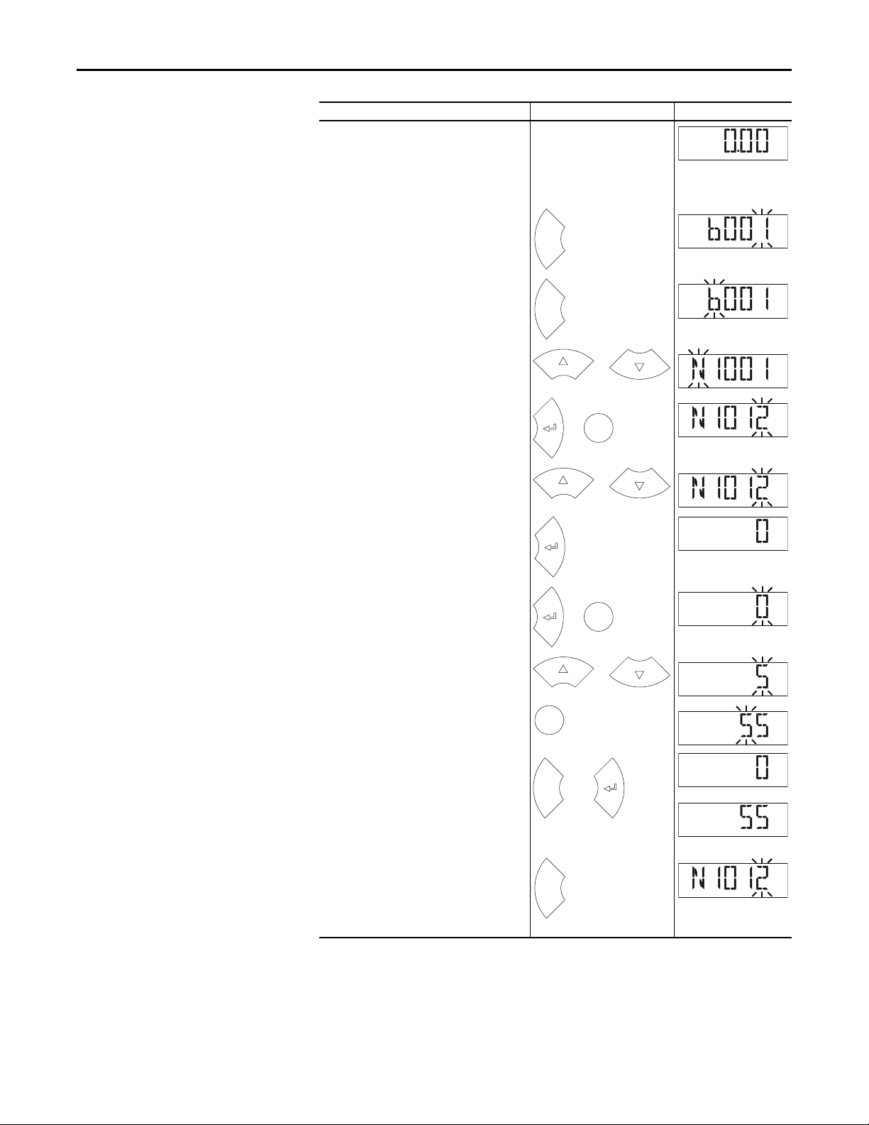
The following is an example of basic integral keypad and display functions. This
example provides basic navigation instructions and illustrates how to program a
parameter.
The Dual-port EtherNet/IP adapter Device parameters can be accessed on the
drive keypad via the “N” (Network) group. Note that the parameters in the “N”
group will appear offset from the Device parameter numbers referenced in this
manual by 1000 (decimal) on the LCD display.
on page 161.
on page 125. For definitions of
).
Rockwell Automation Publication 520COM-UM003A-EN-E - June 2013 25
Page 26
Chapter 3 Configuring the Adapter
HERT
Z
FWD
Esc
FWD
Esc
FWD
or
FWD
Sel
or
FWD
or
FWD
FWD
Sel
or
PROGRAM
FWD
or
PROGRAM
FWD
Sel
PROGRAM
FWD
Esc
or
FWD
FWD
or
Esc
FWD
Step Key(s) Example Display
1. When power is applied, the last user-selected
Basic Display Group parameter number is briefly
displayed with flashing characters. The display
then defaults to that parameter’s current value
(Example shows the value of b001 [Output
Freq] with the drive stopped).
2. Press Esc to display the Basic Display Group
parameter number shown on power-up. The
parameter number will flash.
3. Press Esc to enter the parameter group list. The
parameter group letter will flash.
4. Press the Up Ar row or Down Arrow to scroll
through the group list (b, P, t, C, L, d, A, f, N, M,
and Gx).
5. Press Enter or Sel to enter a group. The right
digit of the last viewed parameter in that group
will flash.
6. Press the Up Ar row or Down Arrow to scroll
through the parameter list.
7. Press Enter to view the value of the parameter.
Or
Press Esc to return to the parameter list.
8. Press Enter or Sel to enter Program Mode and
edit the value. The right digit will flash and the
word Program on the LCD display will light up.
9. Press the Up Arrow or Down Arrow to change
the parameter value.
10. If desired, press Sel to move from digit to digit
or bit to bit. The digit or bit that you can change
will flash.
11. Press Esc to cancel a change and exit Program
Mode.
Or
Press Enter to save a change and exit Program
Mode.
The digit will stop flashing and the word
Program on the LCD display will turn off.
12. Press Esc to return to the parameter list.
Continue to press Esc to back out of the
programming menu.
If pressing Esc does not change the display, then
b001 [Output Freq] is displayed. Press Enter or
Sel to enter the group list again.
26 Rockwell Automation Publication 520COM-UM003A-EN-E - June 2013
Page 27
Configuring the Adapter Chapter 3
Para meters
Groups
Linear List
Changed Params
DIAG
PAR A M DSEL MEM SEL
Sel
Device Select
DSI Devices
DIAG PARAM
DSEL MEM SEL
and
DSI Devices
PowerFlex 525
25-COMM-E2P
and
DSI Devices
PowerFlex 525
25-COMM-E2P
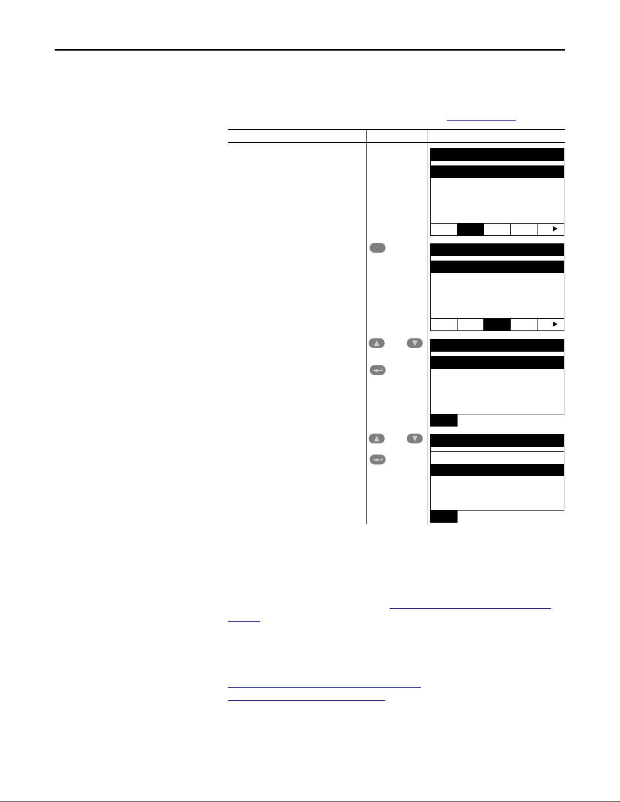
Using the PowerFlex 4-Class HIM to Access Parameters
The PowerFlex 4-class HIM can be used to access parameters in the drive (see
basic steps shown below). It is recommended that you read through the steps for
your HIM before performing the sequence. For additional HIM information,
refer to the HIM Quick Reference card, publication 22HIM-QR001
Step Key(s) Example Display
1. Power up the drive. Then connect the HIM
to the DSI port of the drive. The Parameters
tab for the drive will be displayed.
2. Press Sel until the DSEL tab is selected.
3. Select DSI Device in the DSEL tab if it is not
already selected using the Up Arrow or
Down Arrow.
Press Enter to selec t DSI Device.
.
Setting the Adapter Node Address
4. Press the Up Arrow or Down Arrow to scroll
to 25-COMM-E2P.
Press Enter to reload the HIM to browse
only the Communication Adapter (25COMM-E2P) parameters.
To display the Host parameters, repeat steps 1 through 3 and select “PowerFlex
525” at step 3.
When the Node Address switches (see Setting the Node Address Switches on
page 18) are set to a value other than 001...254 or 888, Device parameter 04 [Net
Addr Sel] determines the source for the adapter node address. By default, the
Node Address switches are set to 999 and Device parameter 04 [Net Addr Sel] is
set to 3 “DHCP”. This combination selects a DHCP server as the source for the
node address. To use a BOOTP or DHCP server to set the node address, see
Using a BOOTP or DHCP Ser ver
Using Adapter Parameters
Rockwell Automation Publication 520COM-UM003A-EN-E - June 2013 27
on page 31.
on page 28. To use adapter parameters, see
Page 28
Chapter 3 Configuring the Adapter
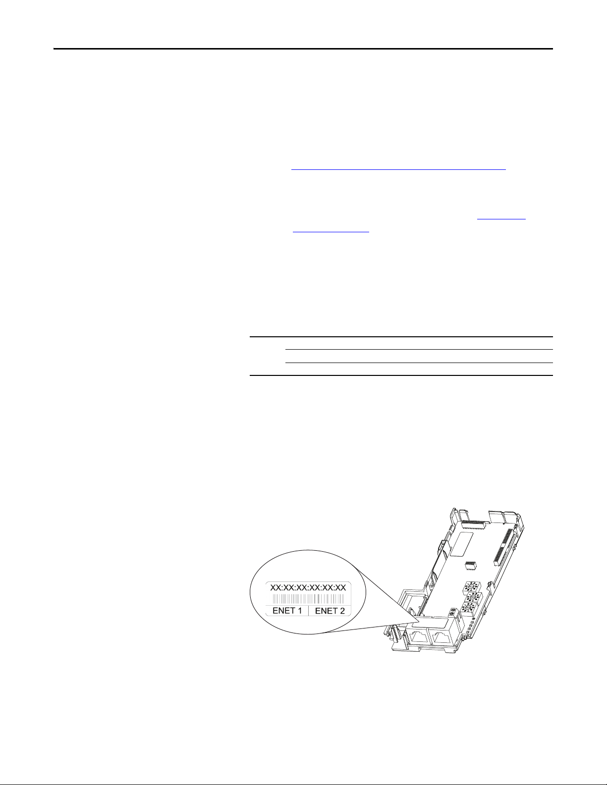
TIP
Ethernet Address label example
Using a BOOTP or DHCP Server
By default, the adapter is configured to accept an IP address, subnet mask, and
gateway address from a DHCP server. You can select from a variety of DHCP/
BOOTP utilities.
The instructions below use the DHCP/BOOTP Utility (version 2.3 or greater),
a free stand-alone program from Rockwell Automation that incorporates the
functionality of standard DHCP/BOOTP utilities with a graphical interface. It
is available from http://www.ab.com/networks/ethernet/bootp.html
Readme file and online Help for directions and more information.
If desired, you can disable BOOTP and configure the IP address, subnet mask,
and gateway address using parameters. For details, see Using Adapter
Parameters on page 31.
. See the
Configuring the Adapter Using a DHCP/BOOTP Utility
1. Depending on the type of server (BOOTP or DHCP) being used, set
Device parameter 04 [Net Addr Sel] to either 2 “BOOTP” or 3 “DHCP”
respectively.
Options 1“Parameters”
2“BOOTP”
3 “DHCP” (Default)
2. Verify and note the adapter’s hardware Ethernet Address (MAC), which
will be used in Step 7. There are two ways to do this:
• Use the PowerFlex 525 drive’s keypad or a HIM to access the diagnostic
items of the drive. Scroll to items 34 [HW Addr 1] through 39 [HW
Addr 6] to view the adapter’s hardware Ethernet Address (MAC).
Finally, convert these decimal values to a hex value.
• Locate the adapter’s hardware Ethernet Address (MAC) label on the
ENET1/ENET2 ports (provided with the adapter).
28 Rockwell Automation Publication 520COM-UM003A-EN-E - June 2013
Page 29
Configuring the Adapter Chapter 3
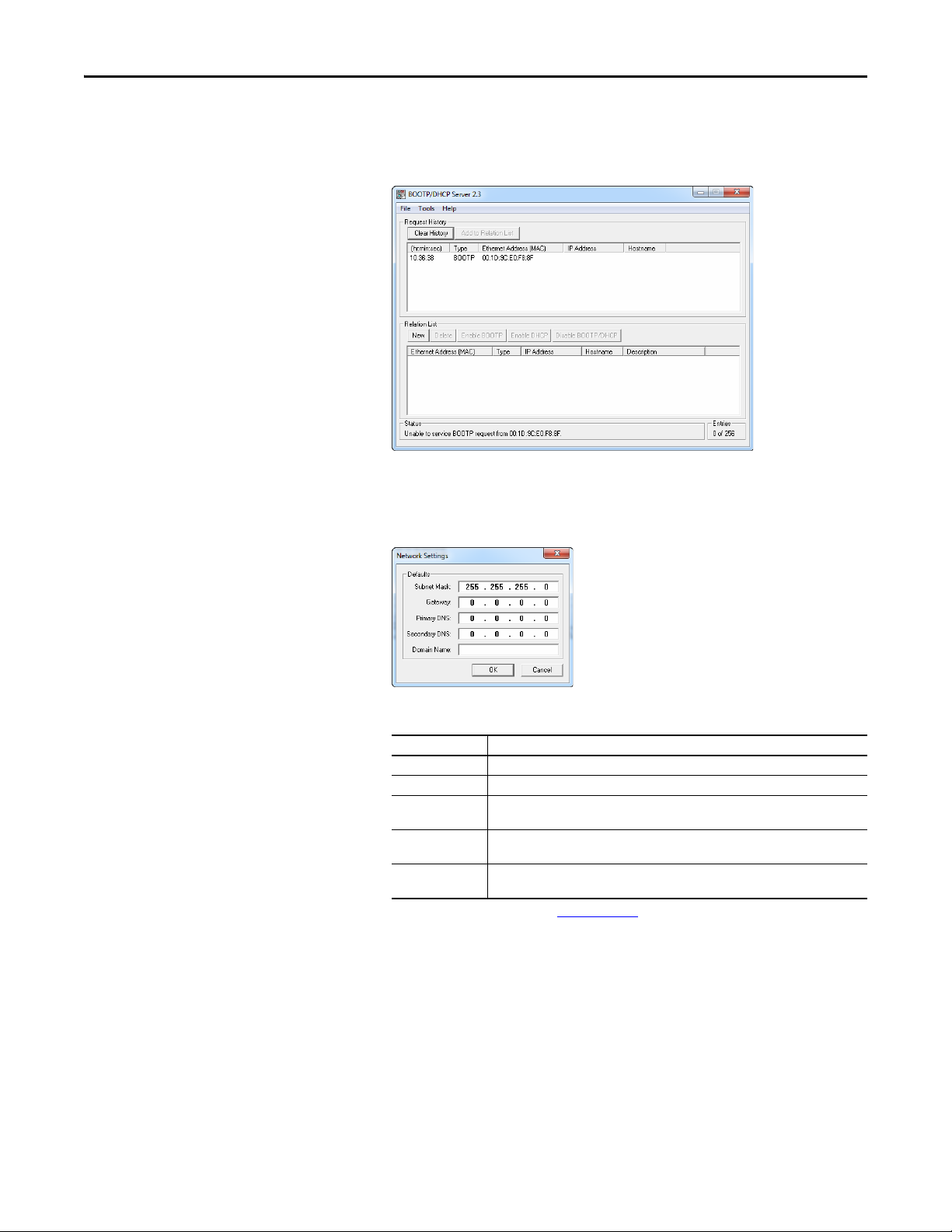
3. On a computer connected to the EtherNet/IP network, start the
BOOTP/DHCP software. The BOOTP/DHCP Server window
appears.
4. To properly configure devices on your EtherNet/IP network, you must
configure settings in the BOOTP/DHCP software to match the network.
Select To o l s > Net work Settings to display the Network Settings window.
5. Edit the following:
Box Type
Subnet Mask
Gateway
Primary DNS The address of the primary DNS server to be used on the local end of the link for
Secondary DNS Optional – the address of the secondary DNS server to be used on the local end of the
Domain Name The text name corresponding to the numeric IP address that was assigned to the server
(1) For definitions of these terms, see the Glossary on page 161.
(1)
(1)
The subnet mask for the adapter’s network.
The IP address of the gateway device on the adapter’s network.
negotiating with remote devices.
link for negotiating with remote devices when the primary DNS server is unavailable.
that controls the network.
6. Click OK to apply the settings. Devices on the network issuing BOOTP/
DHCP requests appear in the BOOTP/DHCP Request History list.
Rockwell Automation Publication 520COM-UM003A-EN-E - June 2013 29
Page 30
Chapter 3 Configuring the Adapter
TIP
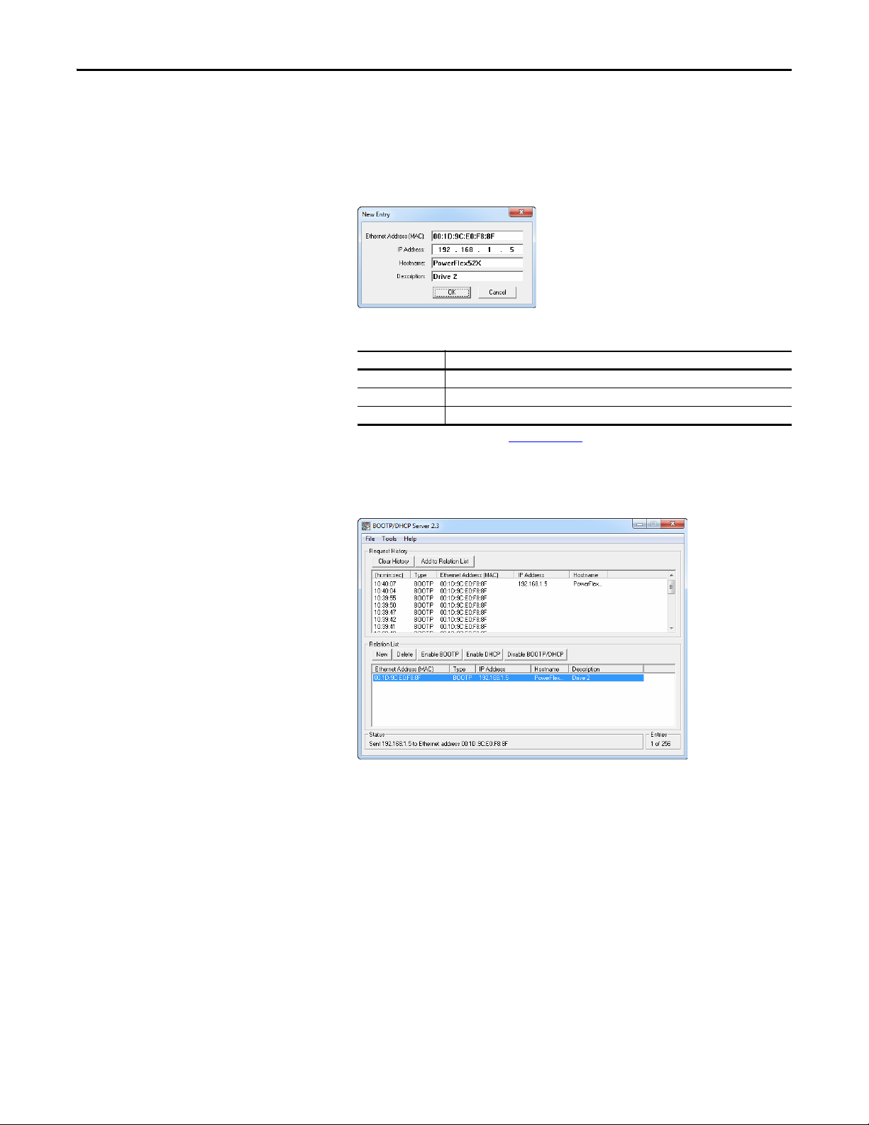
7. In the BOOTP/DHCP Request History list, either double-click the
adapter’s Ethernet Address (MAC) noted in Step 2, or click New in the
Relation List. The New Entry window appears. In the first case, the
Ethernet Address (MAC) is automatically entered. In the latter case, you
must manually enter it.
8. Edit the following:
Box Type
(1)
IP Address
Host Name Optional
Description Optional
(1) For definitions of these terms, see the Glossary on page 161.
A unique IP address for the adapter
9. Click OK to apply the settings. The adapter appears in the Relation List
with the new settings.
10. To assign this configuration to the adapter, select the device in the Relation
List and click Disable BOOTP/DHCP. When power is cycled on the
drive, the adapter will use the configuration you assigned it and not issue
new BOOTP/DHCP requests.
To enable BOOTP for an embedded adapter that has had BOOTP
disabled, first select the adapter in the Relation List. Then, depending
on the type of server, click Enable BOOTP or Enable DHCP and,
lastly, reset the adapter or power cycle the drive.
11. To save the Relation List, select File > Save.
30 Rockwell Automation Publication 520COM-UM003A-EN-E - June 2013
Page 31

Configuring the Adapter Chapter 3
IMPORTANT
192.168.1.62
[IP Addr Cfg 1]
[IP Addr Cfg 2]
[IP Addr Cfg 3]
[IP Addr Cfg 4]
Using Adapter Parameters
By default, the adapter is configured to accept an IP address, subnet mask, and
gateway address from a DHCP server. If you want to set these attributes using
parameters instead, you must first change the source for the node address to
“Parameters” and then set these network address parameters in the adapter.
Changing the Source for the Node Address
1. Verify that the Node Address switches (see Setting the Node Address
Switches on page 18) are set to any value other than 001...254 or 888. The
default setting is 999.
2. Set the value of Device parameter 04 [Net Addr Sel] to 1“Parameters”.
Options 1“Parameters”
2“BOOTP”
3 “DHCP” (Default)
3. Reset the adapter; see Resetting the Adapter
Device parameter 04 [Net Addr Sel] must be set to 1 “Parameters” to
configure the IP address, subnet mask, and gateway address using
adapter parameters.
on page 36.
Setting an IP Address Using Parameters
1. Veri fy th at Device parameter 04 [Net Addr Sel] is set to 1“Parameters”.
2. Set the value of Device parameters 06 [IP Addr Cfg 1] through
09 [IP Addr Cfg 4] to a unique IP address.
3. Reset the adapter; see Resetting the Adapter
on page 36.
The NET A status indicator will be steady green or flashing green if the IP
address is correctly configured.
Setting a Subnet Mask Using Parameters
1. Veri fy th at Device parameter 04 [Net Addr Sel] is set to 1“Parameters”.
Rockwell Automation Publication 520COM-UM003A-EN-E - June 2013 31
Page 32

Chapter 3 Configuring the Adapter
255.255.255.0
[Subnet Cfg 1]
[Subnet Cfg 2]
[Subnet Cfg 3]
[Subnet Cfg 4]
192.168.1.1
[Gateway Cfg 1]
[Gateway Cfg 2]
[Gateway Cfg 3]
[Gateway Cfg 4]
TIP
2. Set the value of Device parameters 10 [Subnet Cfg 1] through
13 [Subnet Cfg 4] to the desired value for the subnet mask.
Setting the Data Rate
3. Reset the adapter; see Resetting the Adapter
on page 36.
Setting a Gateway Address Using Parameters
1. Veri fy th at Device parameter 04 [Net Addr Sel] is set to 1“Parameters”.
2. Set the value of Device parameters 14 [Gateway Cfg 1] through
17 [Gateway Cfg 4] to the desired value for the gateway address.
3. Reset the adapter by power cycling the drive.
By default, the adapter automatically detects the data (baud) rate and duplex
setting used on the network. If you need to set a specific data rate and duplex
setting, the value of Device parameters 18 [Net Rate Cfg 1] determines the
Ethernet data rate and duplex setting that will be uses to communicate on the
adapter’s ENET1 network port. For definitions of data rate and duplex, see the
Glossary
on page 161.
1. Set the value of Device parameter 18 [Net Rate Cfg 1] to the data rate at
which your network is operating.
Options 0 “Autodetect” (Defau lt)
1 “10Mbps Full”
2 “10Mbps Half”
3 “100Mbps Full”
4 “100Mbps Half”
Auto detection of data rate and duplex works properly only if the
device (usually a switch) on the other end of the cable is also set to
automatically detect the data rate/duplex. If one device has the data
rate/duplex hard-coded, the other device must be hard-coded to the
same settings.
32 Rockwell Automation Publication 520COM-UM003A-EN-E - June 2013
Page 33

Configuring the Adapter Chapter 3
TIP
IMPORTANT
If the adapter’s ENET2 network port will be used to connect another drive
in a linear or DLR network topology, set the value of Device parameter
20 [Net Rate Cfg 2] to the appropriate data rate.
Using Master-Slave Hierarchy
2. Reset the adapter; see Resetting the Adapter
A hierarchy determines the type of device with which the adapter exchanges data.
In a Master-Slave hierarchy, the adapter exchanges data with a master, such as a
scanner or bridge.
on page 36.
Configuring a Master-Slave Hierarchy
The controller I/O image can have anywhere from zero to eight (four In and four
Out) additional 16-bit parameters called Datalinks. They are configured using
Host parameters C161 [Opt Data In 1] through C164 [Opt Data In 4], and
C165 [Opt Data Out 1] through C168 [Opt Data Out 4]. The number of
Datalinks actively used is controlled by the connection size in the controller and
the in/out parameters. See the respective controller example sections in
Configuring the I/O
size.
When using a ControlLogix or CompactLogix controller and the Generic
Profile, or a MicroLogix 1100/1400 controller, configure the Datalink
parameters now as described in this section.
on page 39 for more information on setting the connection
When using a ControlLogix or CompactLogix controller and a drive Add-On
Profile for RSLogix 5000 (version 17 or greater) or Logix Designer (version 21 or
greater) software, there is no need to configure Datalink parameters at this
time. They will be assigned when configuring the drive Add-On Profile (see
Adding the Drive/Adapter to the I/O Configuration
on page 42).
Enabling Datalinks To Write Data
Always use the Datalink parameters in consecutive numerical order, starting
with the first parameter. For example, use Host parameters C165, C166, and
C167 to configure three Datalinks to write data. Otherwise, the network I/O
connection will be larger than necessary, which needlessly increases controller
response time and memory usage.
Host parameters C165 [Opt Data Out 1] through C168 [Opt Data Out 4]
control which parameters in the drive send values to the network. To configure
these parameters, set them to the drive parameter number you want to correlate
them to.
The following steps are required to enable Datalinks to write data:
Rockwell Automation Publication 520COM-UM003A-EN-E - June 2013 33
Page 34

Chapter 3 Configuring the Adapter
IMPORTANT
1. Set the values of only the required number of contiguous drive-to-network
Datalinks needed to write data to the network and that are to be included
in the network I/O connection.
2. Reset the adapter; see Resetting the Adapter
After the above steps are complete, the adapter is ready to send output data and
transfer status data to the master (controller). Next, configure the controller to
recognize and transmit I/O to the adapter. See Configuring the I/O
on page 36.
on page 39.
Enabling Datalinks To Read Data
Always use the Datalink parameters in consecutive numerical order, starting
with the first parameter. For example, use Host parameters C161, C162, and
C163 to configure three Datalinks to read data. Otherwise, the network I/O
connection will be larger than necessary, which needlessly increases controller
response time and memory usage.
Host parameters C161 [Opt Data In 1] through C164 [Opt Data In 4]
configure which parameters in the drive receive values from the network. To
configure these parameters, set them to the parameter number you wish to
correlate them to.
The following steps are required to enable Datalinks to read data:
1. Set the values of only the required number of contiguous network-to-drive
Datalinks needed to read data from the network and that are to be
included in the network I/O connection.
Setting a Fault Action
2. Reset the adapter; see Resetting the Adapter
After the above steps are complete, the adapter is ready to receive input data from
the master (controller). Next, configure the controller to recognize and transmit
I/O to the adapter. See Configuring the I/O
By default, when communications are disrupted (the network cable is
disconnected) and/or the controller is idle (in program mode or faulted), the
drive responds by faulting if it is using I/O from the network. You can configure a
different response to these events:
• Disrupted I/O communication by using Device parameter
23 [Comm Flt Action].
on page 36.
on page 39.
34 Rockwell Automation Publication 520COM-UM003A-EN-E - June 2013
Page 35

Configuring the Adapter Chapter 3
• An idle controller by using Device parameter 24 [Idle Flt Action].
ATT EN TI ON : Risk of injury or equipment damage exists. Device parameters 23
[Comm Flt Action] and 24 [Idle Flt Action] respectively let you determine the
action of the adapter and drive if communications are disrupted or the
controller is idle. By default, these parameters fault the drive. You may
configure these parameters so that the drive continues to run, however,
precautions should be taken to ensure that the settings of these parameters do
not create a risk of injury or equipment damage. When commissioning the
drive, verify that your system responds correctly to various situations (a
disconnected network cable or controller in idle state).
Changing the Fault Action
Set the values of Device parameters 23 [Comm Flt Action] and 24 [Idle Flt
Action] to the desired responses:
Value Action Description
0 Fault The drive is faulted and stopped. Datalink data is no longer sent to the drive. (Default)
1 Stop The drive is stopped as per Host parameter P045 [Stop Mode] setting. Datalink data sent to
2 Zero Data The drive is sent “0” values for all Reference and Datalink data. This does not command a stop.
3 Hold Last The drive continues in its present state.
4 Send Flt Cfg The drive is sent the Reference and Datalink data that you set in the fault configuration
the drive remains unchanged.
parameters (Device parameters 25 [Flt Cfg Logic], 26 [Flt Cfg Ref], and 27 [Flt Cfg DL 1]
through 30 [Flt Cfg DL 4]).
Changes to these parameters take effect immediately. A reset is not required. If
communication is disrupted and then re-established, the drive will automatically
receive commands over the network again.
If Multi-Drive mode is used, the same fault action is used by the adapter for all of
the drives it controls (Drive 0...4).
Setting the Fault Configuration Parameters
When setting Device parameters 23 [Comm Flt Action] and 24 [Idle Flt
Action] to 4 “Send Flt Cfg,” the values in the following parameters are sent to the
drive after a communications fault and/or idle fault for drive control fault occurs.
You must set these parameters to values required by your application.
Parameter Description
25 [Flt Cfg Logic] A 16-bit integer value sent to the drive for Logic Command.
26 [Flt Cfg Ref] A 16-bit integer value sent to the drive for Reference.
27 [Flt Cfg DL 1] through
30 [Flt Cfg DL 4]
Changes to these parameters take effect immediately. A reset is not required.
A 16-bit integer value sent to the drive for a Datalink.
Rockwell Automation Publication 520COM-UM003A-EN-E - June 2013 35
Page 36

Chapter 3 Configuring the Adapter
IMPORTANT
Resetting the Adapter
Restoring Adapter Parameters to Factory Defaults
Changes to switch settings or some adapter parameters require that you reset the
adapter before the new settings take effect. You can reset the adapter by cycling
power to the drive or by using Device parameter 22 [Reset Module].
ATT EN TI ON : Risk of injury or equipment damage exists. If the adapter is
transmitting control I/O to the drive, the drive may fault when you reset the
adapter. Determine how your drive will respond before resetting the adapter.
Set Device parameter 22 [Reset Module] to 1“Reset Module”.
Setting for Device Parameter 22 [Reset Module]
Value Description
0 Ready (Default)
1 Reset Module
2Set Defaults
When you enter 1 “Reset Module”, the adapter will be immediately reset. An
alternate method to reset the adapter is by power cycling the drive.
Set Device parameter 22 [Reset Module] to 2 “Set Defaults”.
Setting for Device Parameter 22 [Reset Module]
Value Description
0 Ready (Default)
1 Reset Module
2Set Defaults
When you enter 2 “Set Defaults”, the adapter will set all of its parameters to their
factory default values.
When performing a Set Defaults action, the drive may detect a conflict and
then not allow this function to occur. If this happens, first resolve the conflict
and then repeat a Set Defaults action. Common reasons for a conflict include
the drive running or a controller in Run mode.
After performing a Set Defaults action, you must enter 1 “Reset Module” or
power cycle the drive so that the new values take effect. Thereafter, this
parameter will be restored to a value of 0 “Ready”.
36 Rockwell Automation Publication 520COM-UM003A-EN-E - June 2013
Page 37

Configuring the Adapter Chapter 3
Viewing the Adapter Status Using Parameters
Updating the Adapter Firmware
The following Device parameters provide information about the status of the
adapter. You can view these parameters at any time using the PowerFlex
22-HIM-A3 or 22-HIM-C2S HIM or Connected Components Workbench.
Dual-Port EtherNet/IP Adapter Status Parameters
Name Description
02 [DLs From Net Act] Displays the number of controller-to-drive Datalinks that are included in the network
I/O connection (controller outputs).
03 [DLs To Net Act] Displays the number of drive-to-controller Datalinks that are included in the network
I/O connection (controller inputs).
05 [Net Addr Src] Displays the source from which the adapter’s node address is taken. The source is
determined by the adapter Node Address switch settings (see Setting the Node
Address Switches on page 18), and the value of Device parameter 04 [Net Addr Sel]
which can be any of the following:
• 1 “Parameters”—uses address from Device parameters 06…09 [IP Addr Cfg x]
• 2 “BOOTP”
• 3 “DHCP”—the default
19 [Net Rate Act 1] The data rate used by the adapter’s ENET1 network port.
21 [Net Rate Act 2] The data rate used by the adapter’s ENET2 network port.
The adapter firmware can be updated over the network or through DSI using a
tool such as the 1203-USB.
When updating firmware over the network or DSI, you can use the Allen-Bradley
ControlFLASH software tool.
To obtain a firmware update for this adapter, go to http://www.ab.com/support/
abdrives/webupdate. This site contains all firmware update files and associated
Release Notes that describe the following items:
• Firmware update enhancements and anomalies.
• How to determine the existing firmware revision.
• How to update the firmware using ControlFLASH.
The adapter firmware can also be updated using ADC (Automatic Device
Configuration). See Using Automatic Device Configuration (ADC) with
RSLogix 5000 or Logix Designer on page 50 for more information.
Rockwell Automation Publication 520COM-UM003A-EN-E - June 2013 37
Page 38

Chapter 3 Configuring the Adapter
Notes:
38 Rockwell Automation Publication 520COM-UM003A-EN-E - June 2013
Page 39

Chapter 4
Configuring the I/O
This chapter provides instructions on how to configure a CompactLogix
controller to communicate with the Dual-port EtherNet/IP adapter and
connected PowerFlex 520-series drive.
Top ic Pa ge
Using RSLinx Classic
CompactLogix Example 40
Limitations in Using MicroLogix 1100/1400 62
39
Using RSLinx Classic
RSLinx Classic, in all its variations (Lite, Gateway, OEM, and so on), is used to
provide a communication link between the computer, network, and controller.
RSLinx Classic requires its network-specific driver to be configured before
communications are established with network devices. To configure the
RSLinxdriver:
1. Start RSLinx and select Communications > Configure Drivers to display
the Configure Drivers window.
2. From the Available Driver Types pull-down box, choose “EtherNet/IP
Driver” and then click Add New… to display the Add New RSLinx Driver
window.
3. Use the default name or type a name and click OK. The “Configure
driver:” window appears.
4. Depending on your application, select either the browse local or remote
subnet option, and click OK. The Configure Drivers window reappears
with the new driver in the Configured Drivers list.
5. Click Close to close the Configure Drivers window. Keep RSLinx
running.
Rockwell Automation Publication 520COM-UM003A-EN-E - June 2013 39
Page 40

Chapter 4 Configuring the I/O
1 (Front)1 (Front)1 (Front)
2 (Rear)
00:00:BC:2E:69:F6
Esc
Sel
1783-ETAP
IP Address 192.168.1.3
1769-L36ERM CompactLogix controller
with embedded EtherNet/IP bridge
IP Address 192.168.1.4
PowerFlex 520-series drive with
25-COMM-E2P adapter (Frame A shown)
Computer wi th
Ethernet connection
6. Verify that your computer recognizes the drive. Select Communications >
RSWho and, in the menu tree, click the “+” symbol next to the Ethernet
driver.
7. Note that two other RSLinx drivers (Ethernet devices or Remote Devices
through Linx Gateway) may be used. Use one of these drivers if the
“EtherNet/IP Driver” cannot see your drive.
CompactLogix Example
After the adapter is configured, the drive and adapter will be a single node on the
network. This section provides the steps needed to configure a simple EtherNet/
IP network. In our example, we will configure a 1769-L36ERM CompactLogix
controller with embedded EtherNet/IP capability to communicate with a drive
using Logic Command/Status, Reference/Feedback, and eight Datalinks (four to
read and four to write) over the network.
40 Rockwell Automation Publication 520COM-UM003A-EN-E - June 2013
Adding the Controller to the I/O Configuration
To establish communications between the controller and adapter over the
network, you must first add the CompactLogix controller and its embedded
EtherNet/IP bridge to the I/O configuration.
Page 41

Configuring the I/O Chapter 4
1. Start RSLogix 5000 or Logix Designer. The application window appears.
Select File > New to display the New Controller window.
Select the appropriate choices for the fields in the window to match your
application. Then click OK. The application window reappears with the
treeview in the left pane.
Note : If you are using a controller without an embedded EtherNet/IP
bridge, you will also need to add the bridge to the I/O configuration. See
the user manual for your controller for details.
2. Configure the IP address/Network Settings on your controller or bridge.
In this example, the Network Settings are set for a private network.
3. Click OK. The controller is now configured for the EtherNet/IP network.
It appears in the I/O Configuration folder. In our example, a
1769-L36ERM controller appears under the I/O Configuration folder
with its assigned name.
Rockwell Automation Publication 520COM-UM003A-EN-E - June 2013 41
Page 42

Chapter 4 Configuring the I/O
There are two ways to add the adapter into the I/O configuration:
• Drive Add-On Profiles (for RSLogix 5000 version 17 or greater, Logix
Designer version 21 or greater)
• Generic Profile (for RSLogix 5000 or Logix Designer, all versions)
These are described in the following separate sections. If your version of
RSLogix 5000 or Logix Designer software supports drive Add-On Profiles, we
recommend using this method.
Using Drive AOP (Add-On Profiles) with RSLogix 5000 or Logix Designer
When using the drive Add-On Profiles (with RSLogix 5000 vesion 17 or greater,
or Logix Designer version 21 or greater) compared to the Generic Profile (all
versions), the drive Add-On Profiles provide these advantages:
• Profiles for specific drives that provide descriptive controller tags for basic
control I/O words (Logic Command/Status and Reference/Feedback)
and Datalinks. Additionally, Datalinks automatically take the name of the
drive parameter to which they are assigned. These profiles virtually
eliminate I/O mismatch errors and substantially reduce drive
configuration time.
• New Drive tab eliminates the need for a separate drive software
configuration tool.
• Drive configuration settings are saved as part of the RSLogix 5000 or
Logix Designer project file (.ACD) and also downloaded to the controller.
• Drive Add-On Profiles can be updated anytime. When a new drive is used
or to benefit from new updates for Add-On Profiles, you will need the
newest Add-On Profile update. Go to www.ab.com/support/abdrives/
webupdate to download the latest RSLogix 5000 or Logix Designer drive
Add-On Profile.
Adding the Drive/Adapter to the I/O Configuration
To transmit data between the controller and the drive, you must add the drive as a
child device to the parent controller. In this example, RSLogix 5000 software
version 20 is used with drive Add-On Profile version 1.02.
42 Rockwell Automation Publication 520COM-UM003A-EN-E - June 2013
Page 43

Configuring the I/O Chapter 4
TIP
1. In the treeview, right-click on the icon and select New
Module… to display the Select Module window. Expand the Drives group
to display all of the available drives with their communication adapters.
If the PowerFlex drive is not shown, go to www.ab.com/support/
abdrives/webupdate and download the latest drive Add-On Profile.
2. In the Select Module Type window, select the drive and its connected
adapter from the list. For this example, we selected “PowerFlex 525-E2P.”
Then click Create. The drive’s New Module window appears.
Rockwell Automation Publication 520COM-UM003A-EN-E - June 2013 43
Page 44
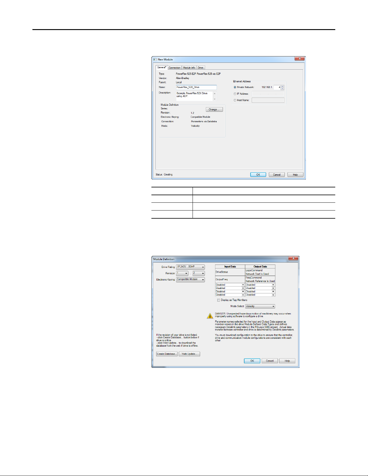
Chapter 4 Configuring the I/O
3. On the General tab, edit the following data about the drive:
Box Setting
Name A name to identify the drive.
Description Optional – description of the drive.
IP Address The IP address of the adapter.
4. On the New Module window in the Module Definition section, click
Change… to launch the Module Definition window and begin the drive
configuration process.
44 Rockwell Automation Publication 520COM-UM003A-EN-E - June 2013
Page 45

Configuring the I/O Chapter 4
TIP
5. In the Module Definition window, edit the following information:
You may create a database from a network accessible drive using the
Create Database... button (Recommended if missing version of drive
or peripheral being used).
Box Setting
Drive Rating The voltage and horsepower rating of the drive. If the drive rating is not listed, the drive
Revision The major and minor revision of the firmware (database) in the drive. If the drive’s major
Electronic Keying Compatible Module. The “Compatible Module” setting for Electronic Keying ensures the
Input Data Assigns drive or connected peripheral parameters to be READ by the controller using
Output Data Assigns drive or connected peripheral parameters to be WRITTEN by the controller using
Mode Select Sets the I/O configuration to either Velocity or Position mode.
database is not installed on your computer. To get the drive rating, use the Create
Database…, or Web Update… button described above.
and minor revision is not available, the drive database is not installed on your computer. To
get the correct database revision, use one of the following buttons at the bottom left of the
Module Definition window:
•Create Database… Creates a database from an online network drive. Clicking this
button displays an RSLinx RSWho window. Browse to the online drive (PowerFlex 525),
select it, and click OK. The database will be uploaded and stored on the computer.
Thereafter, close the Module Definition window and then re-open it to display the new
revisio n.
• Web Update… When a drive is not available online, opens the Allen-Bradley Drives
Web Updates web site to download a specific database file. After downloading the file,
close the Module Definition window and then re-open it to display the new revision.
physical module is consistent with the software configu ration before the controller and
bridge make a connection. Therefore, ensure that you have set the correct revision in this
window. See the online Help for additional information on this and other Electronic Keying
settings. If keying is not required, select “Disable Keying.” Drives do not require keying, and
so “Disable Keying” is recommended.
When using RSLogix 5000 (version 20) or Logix Designer (version 21 or greater) software
and Automatic Device Configuration (ADC) with Firmware Supervisor flash support to store
firmware for the drive, always choose “Exact Match.” See the table on page 53
details when using ADC.
Datalinks.
Datalinks.
for full
On the Module Definition window, notice that the automatically-assigned
controller tags Drive Status, Feedback, Logic Command, and Reference
are always used.
Rockwell Automation Publication 520COM-UM003A-EN-E - June 2013 45
Page 46

Chapter 4 Configuring the I/O
IMPORTANT
When using Datalinks you must still assign Host parameters C161 [Opt
Data In 1] through C164 [Opt Data In 4] and C165 [Opt Data Out 1]
through C168 [Opt Data Out 4] to point to the appropriate drive or
connected peripheral parameters. The procedure to configure the
Datalinks on the Module Definition window for the Input Data and
Output Data is the same:
• Click the button to assign a parameter to each input and output
Datalink you require.
Always use the Datalink parameters in consecutive numerical order,
starting with the first parameter. (For example, use parameters C161,
C162, and C163 to configure three Datalinks to write data and/or
parameters C165, C166, C167, and C168 to configure four Datalinks to
read data.) Otherwise, the network I/O connection will be larger than
necessary, which needlessly increases controller response time and
memory usage.
6. Click OK on the Module Definition window to save the drive
configuration and close the window. The drive’s New Module window
reappears.
7. On the New Module window, click the Connection tab.
8. In the “Requested Packet Interval (RPI)” box, set the value to 2.0
milliseconds or greater. This value determines the maximum interval that a
controller should use to move data to and from the adapter. To conserve
bandwidth, use higher values for communicating with low priority devices.
The “Inhibit Module” box, when checked, inhibits the module from
communicating with the RSLogix 5000 or Logix Designer project. When
the “Major Fault On…” box is checked, a major controller fault will occur
when the module’s connection fails while the controller is in the Run
Mode. For this example, leave the “Inhibit Module” and “Major Fault
On…” boxes unchecked.
46 Rockwell Automation Publication 520COM-UM003A-EN-E - June 2013
Page 47

Configuring the I/O Chapter 4
The “Use Unicast Connection over EtherNet/IP” box is checked by
default. This is the recommended setting. When this box is unchecked, the
adapter will send multicast messages on the I/O connection. In this case,
the adapter and the EtherNet/IP bridge must be on the same subnet.
9. Click OK on the New Module window.
The new node (“PowerFlex 525-E2P PowerFlex_52X_Drive” in this
example) now appears under the icon in the I/O Configuration
folder. If you double-click on the Input Controller Tag (see Controller
Input Tags on page 47) and Output Controller Tag (see Controller
Output Tags on page 47), you will see that module-defined data types and
tags have been automatically created. Note that all tag names are defined
and Datalinks include the assigned drive parameter name. After you save
and download the configuration, these tags allow you to access the Input
and Output data of the drive using the controller’s ladder logic.
Controller Input Tags
Controller Output Tags
Saving the I/O Configuration to the Controller
After adding the controller and drive/adapter to the I/O configuration, you must
download the configuration to the controller. You should also save the
configuration to a file on your computer.
Rockwell Automation Publication 520COM-UM003A-EN-E - June 2013 47
Page 48
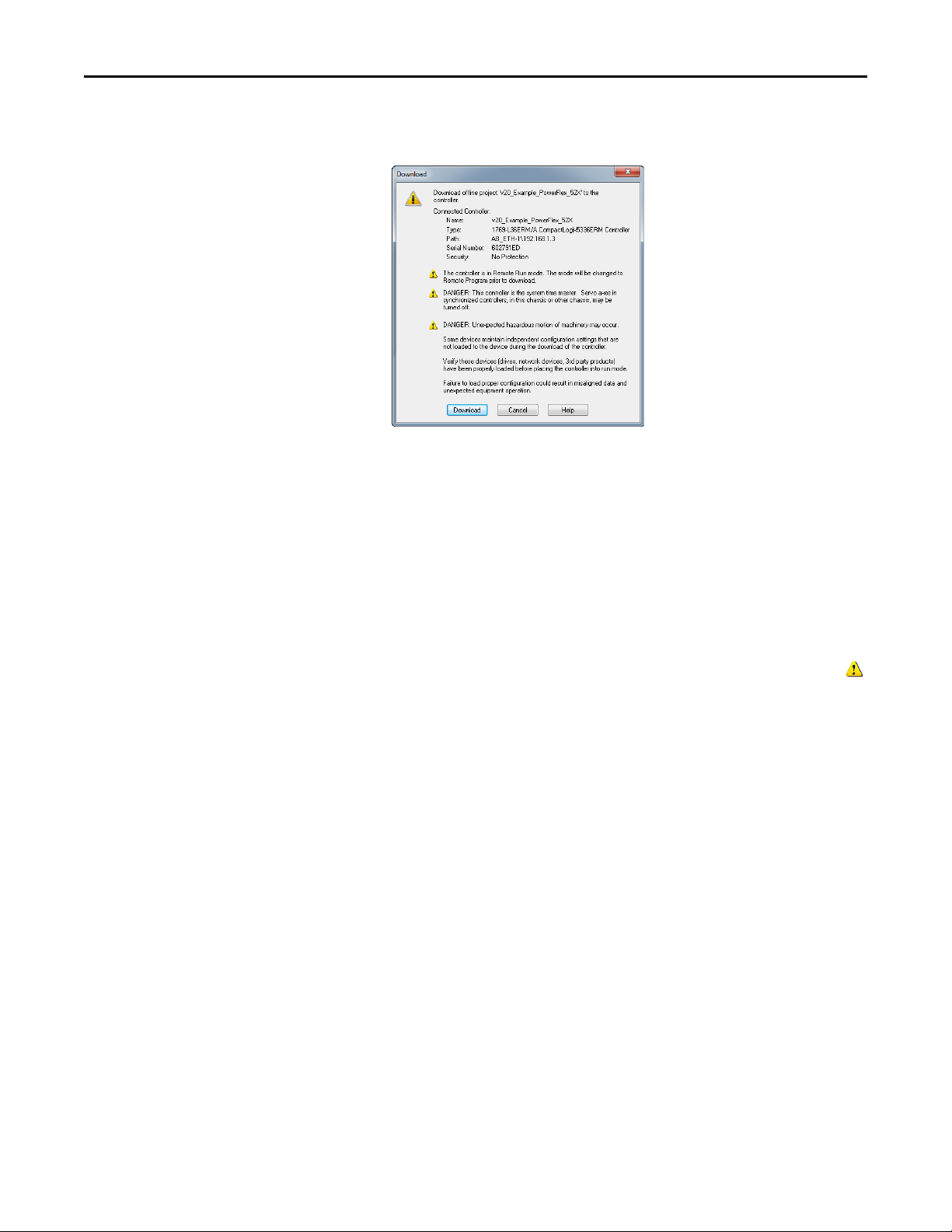
Chapter 4 Configuring the I/O
TIP
1. In the RSLogix 5000 or Logix Designer window, select Communications
> Download. The Download dialog box appears.
If a message box reports that RSLogix 5000 or Logix Designer is unable
to go online, select Communications > Who Active to find your
controller in the Who Active screen. After finding and selecting the
controller, click Set Project Path to establish the path. If your
controller does not appear, you need to add or configure the EtherNet/
IP driver in RSLinx. See the RSLinx online help.
2. Click Download to download the configuration to the controller. When
the download is successfully completed, RSLogix 5000 or Logix Designer
goes into Online Mode and the I/O Not Responding box in the upper-left
of the window should be flashing green. Also, a yellow warning symbol
should be displayed on the I/O Configuration folder in the treeview and
on the drive profile.
3. If the controller was in Run Mode before clicking Download,
RSLogix 5000 or Logix Designer prompts you to change the controller
mode back to Remote Run. In this case, choose the appropriate mode for
your application. If the controller was in Program Mode before clicking
Download, this prompt will not appear.
4. Select File > Save. If this is the first time you saved the project, the Save As
dialog box appears. Navigate to a folder, type a file name, and click Save to
save the configuration to a file on your computer.
5. To ensure that the present project configuration values are saved,
RSLogix 5000 or Logix Designer prompts you to upload them. Click Ye s
to upload and save them.
Correlating the Drive with the Controller
You must now correlate the drive settings to the RSLogix 5000 or Logix Designer
project I/O settings so that they match. This requires loading the project I/O
settings into the drive.
48 Rockwell Automation Publication 520COM-UM003A-EN-E - June 2013
Page 49

Configuring the I/O Chapter 4
TIP
1. In the treeview under I/O Configuration, right-click on the drive profile
(for this example “PowerFlex 525-E2P PowerFlex_52X_Drive”) and select
Properties.
2. Select the Drive tab to begin the correlation process.
After the drive configuration data has been verified, the Drive tab will
display a request to synchronize the configuration with the drive. Click
Accept.
If the Differences Found Screen
on page 50 appears—which is typical,
click Download. This will download the project settings from the
controller to the drive. If Uplo ad is clicked, the drive settings are uploaded
to the controller.
On subsequent connections to the drive (after the initial download),
select Upload.
Rockwell Automation Publication 520COM-UM003A-EN-E - June 2013 49
Page 50

Chapter 4 Configuring the I/O
Differences Found Screen
3. The Drive tab displays the current status of the drive.
If the download is successful, the Drive tab will show a green
indicator in the upper right corner of the window. This tab is extremely
useful for configuring drive parameters, accessing start-up wizards and
troubleshooting.
4. Click OK to close the Module Properties window for the drive.
Using Automatic Device Configuration (ADC) with RSLogix 5000 or Logix Designer
Automatic Device Configuration (ADC) is an RSLogix 5000 (version 20) and
Logix Designer (version 21 or greater) software feature that supports the
automatic download of configuration data upon the Logix controller establishing
50 Rockwell Automation Publication 520COM-UM003A-EN-E - June 2013
Page 51

Configuring the I/O Chapter 4
IMPORTANT
IMPORTANT
an EtherNet/IP network connection to a PowerFlex 525 drive and its associated
peripherals.
• ADC is not available for DSI peripherals.
• ADC is not available in Multi-drive mode.
• ADC is only available when the drive is connected using the Dual-port
EtherNet/IP adapter to a compatible controller.
An RSLogix 5000 (version 20) or Logix Designer (version 21 or greater) project
(.ACD file) contains the configuration settings for any PowerFlex drives in the
project. When the project is downloaded to the Logix controller, these settings
are also transferred and reside in the controller’s memory. Prior to ADC in
RSLogix 5000 (version 20) or Logix Designer (version 21 or greater),
downloading PowerFlex 525 configuration data was a manual process where the
user would open the Drive tab in the respective drive Add-On Profile (AOP) in
the application and click on the Download icon. ADC now automates the
process and saves the user time. It is particularly beneficial in a drive replacement
situation when a production line is down.
ADC can also work in tandem with Firmware Supervisor. If Firmware Supervisor
is set up and enabled for a drive (“Exact Match” keying must be used), the drive/
peripheral will be automatically flashed (if necessary) prior to any ADC
operation.
Logix “owns” the configuration of the drive. ADC will be triggered any
time the Logix controller detects a configuration signature mismatch
when establishing an EtherNet/IP network I/O connection. The use of
other configuration tools, such as a HIM or Connected Components Workbench
software should be minimized and restricted to monitor-only operation. Any
configuration changes made by these tools will cause a configuration signature
mismatch the next time the Logix controller connects to the device and ADC
will write over any changes made by the other tool(s). Any drive configuration
changes should be made with the drive Add-On Profile.
The drive AOP requires user action to enable ADC. This helps ensure that the
user understands ADC operation prior to turning it on. The drive AOPs also
have an ADC icon on the Drive tab to show general ADC enable/disable status
for the drive:
Icon Meaning
No ports on the drive have ADC enabled.
At least one port on the drive has ADC enabled.
ADC is not supported.
Clicking on the ADC icon will launch the ADC configuration window. This
provides a single, convenient location to enable/disable ADC on the drive.
Rockwell Automation Publication 520COM-UM003A-EN-E - June 2013 51
Page 52

Chapter 4 Configuring the I/O
Configuring a PowerFlex 525 Drive for ADC
ADC is configured within the AOP of the PowerFlex 525 drive. Start by creating
or opening a PowerFlex 525 drive in the RSLogix 5000 or Logix Designer I/O
Configuration folder.
1. In the Module Properties window, select the General tab and click
Change… to open the Module Definition window.
2. Select the appropriate Electronic Keying for your application.
52 Rockwell Automation Publication 520COM-UM003A-EN-E - June 2013
Page 53

Configuring the I/O Chapter 4
TIP
There are three Electronic Keying choices available in the Module
Definition window in the drive AOP, but only two are recommended with
ADC:
Keying Selection Recommendation
Exact Match This selection should only be used if:
Compatible Module This selection is the typical ADC selection when Firmware Supervisor is not used. A replacement
Disabled When using ADC, this selection should generally not be used. This selection allows a replacement
• Your system design specification requires that a replacement drive/peripheral be identical –
down to the Minor revision of firmware (x.xxx).
• You will be implementing Firmware Supervisor flash support in addition to ADC. ControlFlash
firmware kits for the revision of firmware used for each drive/peripheral must be installed on the
PC running RSLogix 5000 or Logix Designer. Flash files can be downloaded from:
http://www.ab.com/support/abdrives/webupdate
drive (including peripherals) will need to have the same or higher firmware revision as the original.
Since drives with newer firmware are required to be compatible with older firmware, this allows
ADC to work without compatibility concerns. Note that if a Series change accompanies a Major
firmware change, the replacement drive may or may not be “compatible” with respect to keying.
drive to have any different Major (x.xxx) and/or Minor (x.xxx) firmware revision. It is up to the user
to provide a replacement that has a firmware revision later than or equal to the original drive. If a
replacement drive with older firmware is used, the ADC download may fail.
Electronic Keying for HIMs and serial converters are disabled by default.
These are typically temporary devices or used for monitoring purposes
only and therefore “do not matter” if they are present or not. You still have
the option to select these to other Keying selections if desired.
Electronic Keying settings for peripherals can be modified in the Drive
tab of the AOP. Select the peripheral tab for the device you wish to
modify, then click Properties.
Click OK when finished.
3. Select the Drive tab and click the ADC icon to open the ADC
Settings.
The ADC Settings window provides a single location for ADC
configuration of the drive’s ports. Global checkboxes at the top of each
column checks or unchecks the entire column. Ports can also be turned
on/off individually. See the checkbox selection information in Step 3 for
additional details.
Click OK when finished.
4. Perform the above steps for each additional PowerFlex 525 drive.
5. Save your project and download the project to the Logix controller.
Rockwell Automation Publication 520COM-UM003A-EN-E - June 2013 53
Page 54

Chapter 4 Configuring the I/O
ADC and Logix Memory
Starting in RSLogix 5000 software version 16, drive configuration settings have
been stored in the project's ACD file which is downloaded and stored in the
controller. The majority of Logix controllers have megabytes of memory
available, so this typically should not be an issue. You can monitor Logix memory
usage in the application in the Controller Properties > Memory tab.
Storing the Drive’s and Peripheral’s Firmware in the Logix Controller (Firmware Supervisor)
The Logix Firmware Supervisor function has been extended to provide firmware
updates for the peripherals connected to the drive. To configure the controller to
check and refresh the correct firmware for the drive and peripherals, perform the
following steps:
1. Verify that “Exact Match” keying is selected in the drive’s and peripherals’
properties screens (the drive’s is in the General tab; the peripherals’ are
under the Drive tab, after right-clicking on each peripheral and choosing
Properti es).
2. Verify that ControlFlash firmware kits for each revision of firmware for
each device that should be stored in the controller have been installed on
the PC running RSLogix 5000 or Logix Designer software.
3. Verify that a CompactFlash or other storage card has been installed in the
controller.
4. Use RSLogix 5000 or Logix Designer to go online with the controller in
Program mode. Download your program if you have not done so already.
5. In the treeview, right-click on the controller folder at the top of the
Controller Organizer and choose Properties . On the Controller
Properties window, select the Nonvolatile Memory tab.
54 Rockwell Automation Publication 520COM-UM003A-EN-E - June 2013
Page 55

Configuring the I/O Chapter 4
IMPORTANT
6. Click Load/Store…. The Nonvolatile Memory Load/Store window
appears.
In the Controller section for the Automatic Firmware Update field, select
“Enable and Store Files to Image,” and click the <-- Store button. You may
see two different continue confirmation dialog boxes relating to
communication disruptions and erasure of the current contents of the
storage card. If okay, click Ye s on each dialog box.
7. The application will go to the Offline state, and the following dialog box
will appear.
Wait a short period of time for the store operation to complete, and then
attempt to go online with the controller again.
Monitoring the ADC Progress
The time it takes for the ADC process to complete will vary from seconds to
several minutes depending on several factors:
• The number of peripherals enabled for ADC.
• If a configuration signature for the drive/peripheral indicates a
configuration download needs to be performed for the given port.
• Whether Firmware Supervisor is enabled and needs to flash the drive and/
or any peripherals.
ADC can automatically reset the drive as part of the configuration process. This
is done because some parameters require a reset before they take effect. If a
drive is being replaced with an out-of-the-box drive, you will typically see one
or more resets during the ADC process.
Rockwell Automation Publication 520COM-UM003A-EN-E - June 2013 55
Page 56

Chapter 4 Configuring the I/O
An operational drive in a running Logix system will have the following status
indicator states:
Status Indicator State Description
PORT Steady Green The adapter is properly connected and is communicating with the drive.
MOD Steady G reen The adapter is operating normally and is transferring I/O data to a controller.
NET A Steady Green The adapter is operating normally and has at least one CIP connection (I/O or
explicit) .
NET B Flashing Green The adapter is transmitting on the network.
See Understanding the Status Indicators
on page 115 for more information.
Additional information may also be displayed on the HIM if it is present (flash
status, etc.).
If ADC is unsuccessful, RSLogix 5000 or Logix Designer software can be used to
get additional information. When online, the drive at issue should have a yellow
triangle next to it in the RSLogix 5000 or Logix Designer project's I/O
Configuration folder. Double-click on the drive to open the drive AOP. The
Connection tab will show a Module Fault code and the Drive tab can help you
identify issues.
ADC Status Field Description
Running Any desired configuration is complete, and the I/O connection is running.
Configuring ADC is currently updating the configuration of the drive or one of its peripherals. Clicking
Firmware Updating ADC is currently updating the firmware of the drive or one of its peripherals. Clicking on
Inhibited The program has the connection inhibited. You can uninhibit the connection on the
Faulted A problem is preventing the controller from connecting to the drive (for example, the
on the Connection tab will show which device is being updated.
the Drive tab will show which device is being updated.
Connection tab.
device at the IP address provided is not a PowerFlex 525 drive). Clicking on the
Connection tab will show the cause (Module Fault). Clicking on the D rive tab may also
show the faulted ports.
Examples of potential issues/solutions are:
Issue Solution
“Compatible module” keying selected, but replacement
drive or peripheral has an earlier firmware revision than the
failed device.
Peripheral is required for connection (“Fail Drive Connection
on Peripheral Error” was checked), but it is missing.
Parameter “out of range” error—ADC wrote a value to a
parameter that was out of range (typically would only
occur during initial commissioning of a drive system).
Replace device with a revision that is later than or equal to
the failed device. If necessar y, use ControlFLASH to flash
replacement device first to an acceptable revision level.
Add required peripheral or remove peripheral from
RSLogix 5000/Logix Designer project for the drive and
download project to the controller.
Use any available drive software tool to view a linear list of
changed parameters to see if the configured value is
outside the minimum/maximum value. The drive AOPs are
the preferred tool and will highlight any out of range
parameter in the Linear List editor. Connected Components
Workbench (version 3 or greater) may also be used.
Using the RSLogix 5000 or Logix Designer Generic Profile
The basic RSLogix 5000 (all versions) or Logix Designer (version 21 or greater)
Generic Profile is only recommended when:
56 Rockwell Automation Publication 520COM-UM003A-EN-E - June 2013
Page 57

Configuring the I/O Chapter 4
• A specific drive profile in other versions of RSLogix 5000 or Logix
Designer software is unavailable.
• Users are already familiar with a Generic Profile and do not want to
convert an existing project to a drive Add-On Profile (RSLogix 5000
version 17 or greater and Logix Designer version 21 or greater).
• A project must maintain specific revision level control.
• The controller cannot be taken offline. RSLogix 5000 (all versions) and
Logix Designer (version 21 or greater) software enables the drive Generic
Profile to be added while the controller is online and in the Run mode.
Adding the Drive/Adapter to the I/O Configuration
To transmit data between the bridge and the drive, you must add the drive as a
child device to the parent bridge.
1. In the treeview, right-click on the icon and select New
Module… to display the Select Module Type window. Expand the
Communications group to display all of the available communication
modules or search for “ETHERNET-MODULE”.
2. Select “ETHERNET-MODULE” from the list in the Select Module Type
window to configure the drive’s embedded EtherNet/IP adapter, and then
click Create. The drive’s New Module window appears.
Rockwell Automation Publication 520COM-UM003A-EN-E - June 2013 57
Page 58
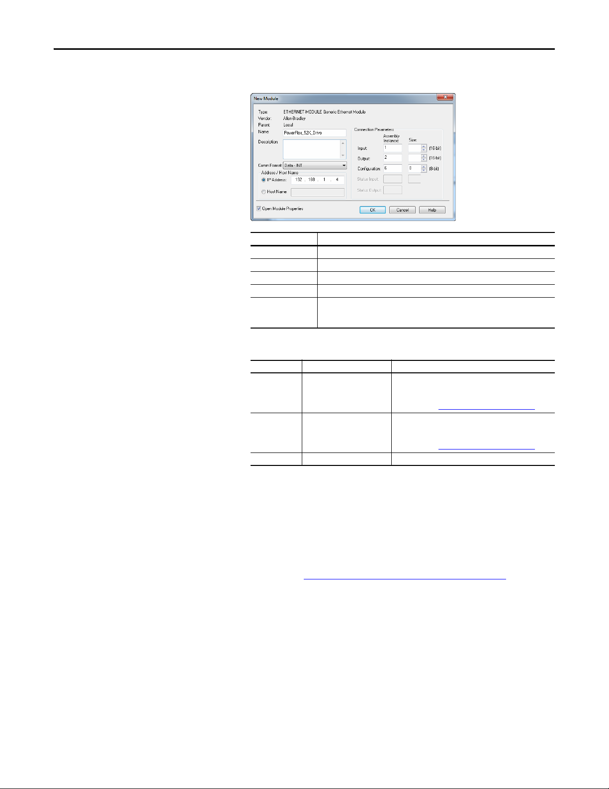
Chapter 4 Configuring the I/O
3. Edit the following information about the drive:
Box Setting
Name A name to identify the drive.
Description Optional – description of the drive.
Comm Format Data – INT (This setting formats the data in 16-bit words.)
IP Address The IP address of the drive.
Open Module
Properties
When this box is checked, clicking OK opens additional module properties screens to
further configure the drive. When unchecked, clicking OK closes the drive’s New
Module screen. For this example, check this box.
4. Under Connection Parameters, edit the following:
Box Assembly Instance Size
Input 1 (This value is required.) The value will vary based on the total number of Host
Output 2 (This value is required.) The value will vary based on the total number of Host
Confi guration 6 (This value is required.) 0 (This value is required.)
parameters [Opt Data In x] used for your application,
either in Single-drive mode (see details below) or Multidrive mode (see Using Multi-Drive Mode
parameters [Opt Data Out x] used for your application,
either in Single-drive mode (see details below) or Multidrive mode (see Using Multi-Drive Mode
on page 87).
on page 87).
Enter the number of 16-bit words that are required for your I/O in the
Input Size and Output Size boxes. Since the adapter always uses the 16-bit
Logic Status, 16-bit Feedback, and two 16-bit words dedicated for
memory allocation of the Generic Ethernet module profile, at least four
16-bit words must be set for the Input Size. The adapter also uses the 16bit Logic Command and 16-bit Reference, requiring at least two 16-bit
words for the Output Size. If any or all of the drive’s eight 16-bit Datalinks
are used (see Configuring a Master-Slave Hierarchy
on page 33), the Input
and Output Size settings must be increased accordingly.
58 Rockwell Automation Publication 520COM-UM003A-EN-E - June 2013
Page 59

Generic Profile Example of I/O Image
IMPORTANT
Adapter
Word and I/O
Logic CommandWord 0
ReferenceWord 1
Datalink 1Word 2
Datalink 2Word 3
Datalink 3Word 4
Datalink 4Word 5
Logic StatusWord 2
FeedbackWord 3
Required
Padword
(1)
Word 0
PadwordWord 1
Datalink 1Word 4
Datalink 2Word 5
Datalink 3Word 6
Datalink 4Word 7
Optional
Required
Optional
Output
Image
(Write)
Input
Image
(Read)
(1) Padwords only apply when using the generic profile. Padwords are not used when using the full-featured drive Add-
On-Profile.
Configuring the I/O Chapter 4
The Host Datalink parameters [Opt Data In x] and [Opt Data Out x] do
not actually contain data. These are user-configurable parameters that
only contain the parameter number of the parameter whose data will
be made available for write/read in the I/O image. See Using Datalinks
on page 66.
For the example below, all four [Opt Data In x] and all four [Opt Data
Out x] parameters are used, resulting in an Input Size of “8” and an
Output Size of “6.”
5. After setting the information in the drive’s New Module window, click
OK. The Module Properties window appears.
Rockwell Automation Publication 520COM-UM003A-EN-E - June 2013 59
Page 60

Chapter 4 Configuring the I/O
6. Click the Connection tab.
7. In the “Requested Packet Interval (RPI)” box, set the value to 2.0
milliseconds or greater. This value determines the maximum interval that a
controller should use to move data to and from the adapter. To conserve
bandwidth, use higher values for communicating with low priority devices.
For this example, leave the “Inhibit Module” and Major Fault On…” boxes
unchecked.
The “Use Unicast Connection over EtherNet/IP” box is checked by
default. This is the recommended setting. When this box is unchecked, the
adapter will send multicast messages on the I/O connection. In this case,
the adapter and the EtherNet/IP bridge must be on the same subnet.
8. Click OK. The new node
(“ETHERNET-MODULE_PowerFlex_52X_Drive” in this example)
now appears under the icon in the I/O Configuration folder. If
you double-click on the Input Controller Tag (see Input Image Controller
Ta g s on page 60) and Output Controller Tag (see Output Image
Controller Tags on page 60), you will see that module-defined data types
and tags have been automatically created. After you save and download the
configuration, these tags allow you to access the Input and Output data of
the drive using the controller’s ladder logic.
Input Image Controller Tags
Output Image Controller Tags
60 Rockwell Automation Publication 520COM-UM003A-EN-E - June 2013
Page 61

Configuring the I/O Chapter 4
TIP
TIP
Saving the I/O Configuration to the Controller
After adding the bridge and drive/adapter to the I/O configuration, you must
download the configuration to the controller. You should also save the
configuration to a file on your computer.
When using RSLogix 5000 or Logix Designer software, you can add the I/O
configuration of a Generic Profile while the controller is online and in the Run
mode.
1. In the RSLogix 5000 or Logix Designer window, select Communications
> Download. The Download dialog box appears.
If a message box reports that RSLogix 5000 or Logix Designer is unable
to go online, select Communications > Who Active to find your
controller in the Who Active screen. After finding and selecting the
controller, click Set Project Path to establish the path. If your
controller does not appear, you need to add or configure the EtherNet/
IP driver in RSLinx. See Using RSLinx Classic
on page 39 for details.
2. Click Download to download the configuration to the controller. When
the download is successfully completed, RSLogix 5000 or Logix Designer
goes into the Online mode and the I/O OK box in the upper-left of the
screen should be steady green.
3. Select File > Save. If this is the first time you saved the project, the Save As
dialog box appears. Navigate to a folder, type a file name, and click Save to
save the configuration to a file on your computer.
4. Any Datalinks that were enabled in the controller and drive during I/O
configuration must also be configured in the drive. Each Datalink being
used must be assigned to a specific parameter in the drive or connected
peripheral (see Configuring a Master-Slave Hierarchy
on page 33). If this is
not done, the controller will receive or send placeholder data instead of
actual drive or peripheral parameter values.
5. Place the controller in Remote Run or Run Mode.
Rockwell Automation Publication 520COM-UM003A-EN-E - June 2013 61
Page 62

Chapter 4 Configuring the I/O
Limitations in Using MicroLogix 1100/1400
Controlling I/O with explicit messages is relatively complex compared to normal
implicit I/O control.
ControlLogix and CompactLogix controllers with EtherNet/IP provide the
easiest and most integrated form of implicit I/O control for a PowerFlex drive.
RSLogix 5000 or Logix Designer programming software for ControlLogix and
CompactLogix controllers contains integrated profiles for PowerFlex drives that,
with a few clicks of the mouse, automatically create all controller tags and an
implicit connection at the specified Requested Packet Interval to control the
drive. This connection is monitored at both ends to ensure that the controller
and drive are communicating. A watchdog will cause a drive fault if the drive does
not respond within approximately 100 milliseconds. Therefore, using a
ControlLogix or CompactLogix controller is by far the much preferred method
of controlling drives on EtherNet/IP.
If you are not using either of these type of controllers, then PowerFlex drives on
EtherNet/IP can be controlled with explicit messages using
MicroLogix 1100/1400 controllers with the following limitations:
• An explicit message is a much slower form of control and is nondeterministic. This means that you cannot guarantee how long the drive
will take to start up or stop when the command is given. Therefore, all
equipment used in this manner should be subject to a risk assessment,
taking into account the mechanical and electrical implementation.
• A timeout value (in seconds) in the embedded EtherNet/IP adapter will
issue a drive fault if a message is not received from the controller within the
specified time. However, the controller has no way of detecting a loss of
communications to the drive until the next cycle of explicit messages. This
is another factor in the risk assessment.
• Any additional drives to be controlled will require additional explicit
messages for their control, and they need to be carefully sequenced. Most
controllers have small communication queues (see its User Manual), which
need to be carefully managed if messages are not to be lost.
• Each controller has a limited number of communication connections (see
its User Manual for maximum connections), which will limit the number
of drives that can be connected.
In summary, unlike a ControlLogix or CompactLogix controller, programming a
MicroLogix 1100/1400 controller using RSLogix 500 software with explicit
messages is more difficult, and produces a more complex program.
62 Rockwell Automation Publication 520COM-UM003A-EN-E - June 2013
Page 63

Chapter 5
Using the I/O
This chapter provides information and examples that explain how to control,
configure, and monitor a PowerFlex 520-series drive using the configured I/O.
Top ic Pa ge
About I/O Messaging
Understanding the I/O Image 64
Using Logic Command/Status 65
Using Reference/Feedback 65
Using Datalinks 66
Example Ladder Logic Program Information 67
CompactLogix Example 67
ATT EN TI ON : Risk of injury or equipment damage exists. The examples in this
publication are intended solely for purposes of example. There are many
variables and requirements with any application. Rockwell Automation, Inc.
does not assume responsibility or liability (to include intellectual property
liability) for actual use of the examples shown in this publication.
63
About I/O Messaging
On CIP-based networks, including EtherNet/IP, I/O connections are used to
transfer the data which controls the PowerFlex drive and sets its Reference. I/O
can also be used to transfer data to and from Datalinks in PowerFlex 520-series
drives.
The adapter includes the Logic Command, Logic Status, Reference, Feedback,
and memory allocation for the Generic Ethernet module profile (all as 16-bit
words) in the controller’s I/O image. This basic I/O must always be configured in
the Ethernet bridge using RSLogix 5000 or Logix Designer software. Additional
I/O, if needed, can be set using up to four Datalinks to write data and/or up to
four Datalinks to read data. When using any combination of these Datalinks, add
one 16-bit word for each Datalink to the basic I/O Input Size and/or Output
Size.
Configuring the Adapter
on page 25 and Configuring the I/O on page 39 discuss
how to configure the adapter and controller on the network for the required I/O.
The Glossary defines the different options. This chapter discusses how to use I/O
after you have configured the drive and controller.
Rockwell Automation Publication 520COM-UM003A-EN-E - June 2013 63
Page 64

Chapter 5 Using the I/O
Understanding the I/O Image
The terms input and output are defined from the controller’s point of view.
Therefore, output I/O is data that is produced by the controller and consumed by
the adapter. Input I/O is data that is produced by the adapter and consumed as
input by the controller. The I/O image will vary based on:
• How many of the drive’s 16-bit Datalinks (Host parameters C161 [Opt
Data In 1] through C164 [Opt Data In 4] and C165 [Opt Data Out 1]
through C168 [Opt Data Out 4]) are used.
Device parameters 02 [DLs From Net Act] and 03 [DLs To Net Act]
must also be configured accordingly if Datalinks are used.
• ControlLogix/CompactLogix Controllers only—The drive Add-On
Profile (AOP) used in RSLogix 5000 (version 17 or greater) or Logix
Designer (version 21 or greater) software, or the Generic Profile (all
versions).
• If Multi-drive mode is enabled, and the number of daisy-chained drives
that are present.
I/O Controller Image
Since the drive Add-On Profile in RSLogix 5000 (version 17 or greater) and
Logix Designer (version 21 or greater) software provides descriptive controller
tags, the I/O image (tag size and location) is automatically configured based on
the drive being used. When using the Generic Profile in RSLogix 5000 or Logix
Designer, however, controller tags are not descriptive.
I/O Image for PowerFlex 525 Drives
on page 64 shows the I/O image when using
all of the 16-bit Datalinks.
I/O Image for PowerFlex 525 Drives
(16-bit Logic Command/Status, Reference/Feedback, and Datalinks)
INT Output Input Using...
INT Drive Add-On Profile INT Generic Profile
0Logic Command0Logic Status 0Padword
1 Reference 1 Feedback 1 Padword
2 Datalink 1 2 Datalink 1 2 Logic Status
3 Datalink 2 3 Datalink 2 3 Feedback
4 Datalink 3 4 Datalink 3 4 Datalink 1
5 Datalink 4 5 Datalink 4 5 Datalink 2
6 Datalink 3
7 Datalink 4
Single drive mode is the typical configuration, where one node consists of a
PowerFlex 520-series drive with a 25-COMM-E2P adapter.
For Multi-Drive mode, where one node can consist of up to five drives, see Using
Multi-Drive Mode on page 87.
64 Rockwell Automation Publication 520COM-UM003A-EN-E - June 2013
Page 65

Using the I/O Chapter 5
Using Logic Command/Status
Using Reference/Feedback
The Logic Command is a 16-bit word of control data produced by the controller
and consumed by the adapter. The Logic Status is a 16-bit word of status data
produced by the adapter and consumed by the controller.
When using a ControlLogix or CompactLogix controller, the Logic Command
word is always INT 0 in the output image and the Logic Status word is always:
• INT 0 in the input image when using the drive Add-On Profile.
• INT 2 when using the Generic Profile.
This manual contains the bit definitions for compatible products available at the
time of publication in Logic Command/Status Words: PowerFlex 525 Drives
on
page 157.
The Reference is a 16-bit word that is produced by the controller and consumed
by the adapter. The Feedback is a 16-bit word produced by the adapter and
consumed by the controller.
When using a ControlLogix or CompactLogix controller, the Reference is always
INT 1 in the output image (see I/O Image for PowerFlex 525 Drives
on page 64)
and the 16-bit Feedback is always:
• INT 1 in the input image when using the drive Add-On Profile.
• INT 3 when using the Generic Profile.
The Reference and Feedback are 16-bit INT values represent drive speed. The
scaling for the speed Reference and Feedback is 0.01 Hz. For example, a 16-bit
INT Reference value of ‘3000’ would equal a Reference of 30.00 Hz. Note that
the commanded maximum speed can never exceed the value of Host parameter
P044 [Maximum Freq]. PowerFlex 525 Drive Example Speed Reference/
Feedback Scaling on page 65 shows example References and their results for a
PowerFlex 525 drive that has its:
• Host parameter P043 [Minimum Freq] set to 10.00 Hz.
• Host parameter P044 [Maximum Freq] set to 50.00 Hz.
PowerFlex 525 Drive Example Speed Reference/Feedback Scaling
Network Reference Value Speed Commanded Value Output Speed Network Feedback Value
10000 100.00 Hz 50.00 Hz
6500 65.00 Hz 50.00 Hz
3250 32.50 Hz 32.50 Hz 3250
0 0.00 Hz 0.00 Hz 0
(1) The drive runs at 50.00 Hz instead of 100.00 Hz or 65.00 Hz because Host parameter P044 [Maximum Freq] sets 50.00 Hz as the
maximum speed.
(1)
5000
(1)
5000
Rockwell Automation Publication 520COM-UM003A-EN-E - June 2013 65
Page 66

Chapter 5 Using the I/O
IMPORTANT
IMPORTANT
There are several parameters in the drive that will override the start source and
speed reference command if enabled. For details on these parameters, see the
PowerFlex 525 drive’s user manual, publication 520-UM001
Attempting to write a negative value to the Speed Reference will result in the
drive ramping to maximum speed due to overflow, the direction of the drive
can only be controlled programmatically with the appropriate bits (bits 4 and
5) in the Command Word.
.
Using Datalinks
A Datalink is a mechanism used by PowerFlex drives to transfer data to and from
the controller. Datalinks allow a drive parameter value to be read or written to
without using an Explicit Message. When enabled, each Datalink occupies one
16-bit word in a ControlLogix, CompactLogix, or MicroLogix controller.
The following rules apply when using PowerFlex 520-series drive Datalinks:
• Datalinks cannot be used with Multi-drive mode.
• The target of a Datalink can be any appropriate Host parameter. For
example, Host parameter P041 [Accel Time 1] can be the target of the
Dual-port EtherNet/IP adapter installed in the drive.
• The data passed through the drive’s Datalink mechanism is determined by
the settings of the following parameters:
– Device Parameter 02 [DLs From Net Act]
– Device Parameter 03 [DLs To Net Act]
– Host parameters C161 [Opt Data In 1] through
C164 [Opt Data In 4]
– Host parameters C165 [Opt Data Out 1] through
C168 [Opt Data Out 4]
A reset is always required after configuring Datalinks so that the
changes take effect.
• When an I/O connection that includes Datalinks is active, those Datalinks
being used are locked and cannot be changed until that I/O connection
becomes idle or inactive.
• When you use a Datalink to change a value, the value is NOT written to
the Non-Volatile Storage (NVS). The value is stored in volatile memory
and lost when the drive loses power. Thus, use Datalinks when you need to
change a value of a parameter frequently.
Datalinks for PowerFlex 520-series drive peripherals (embedded EtherNet/IP
adapter on PowerFlex 525 drives only and option modules such as an encoder or
communication adapter) are locked when the peripheral has an I/O connection
with a controller. When a controller has an I/O connection to the drive, the drive
does not allow a reset to defaults, configuration download or anything else that
could change the makeup of the I/O connection in a running system. The I/O
connection with the controller must first be disabled to allow changes to the
respective Datalinks.
66 Rockwell Automation Publication 520COM-UM003A-EN-E - June 2013
Page 67

Using the I/O Chapter 5
Depending on the controller being used, the I/O connection can be disabled by:
• Inhibiting the module in RSLogix 5000 or Logix Designer software
• Putting the controller in Program mode
• Placing the scanner in idle mode
• Disconnecting the drive from the network
Example Ladder Logic Program Information
The example ladder logic programs in the sections of this chapter are intended for
PowerFlex 520-series drives.
Functions of the Example Programs
The example programs enable you to:
• Receive Logic Status information from the drive.
• Send a Logic Command to control the drive (for example, start, stop).
• Send a Reference to the drive and receive Feedback from the drive.
• Send/receive Datalink data to/from the drive.
Logic Command/Status Words
These examples use the Logic Command word and Logic Status word for
PowerFlex 525 drives. See Logic Command/Status Words: PowerFlex 525 Drives
on page 157 to view details.
CompactLogix Example
Creating Ladder Logic Using the Drive Add-On Profiles in RSLogix 5000 or Logix Designer Software
Since the drive Add-On Profile automatically created descriptive controller tags
(see Controller Input Tags
I/O image in Configuring the I/O
control and monitor the drive without creating any ladder logic program.
However, if you intend to use Human Machine Interface devices (PanelView,
etc.) to operate the drive and view its status, you will need to create descriptive
user-defined Program tags (see CompactLogix Program Tags for Drive Add-On
Profile Ladder Logic Program Example on page 68) and a ladder logic program
that will pass the Controller tag data to the Program tags.
Rockwell Automation Publication 520COM-UM003A-EN-E - June 2013 67
and Controller Output Tags on page 47) for the entire
on page 39, you can use these tags to directly
Page 68

Chapter 5 Using the I/O
Copy File
Source
Dest
Length
PowerFlex_52X_Drive:I.OutputFreq
Speed_Feedback
1
COP
PowerFlex_52X_Drive:I.DriveStatus_Ready Status_Ready
PowerFlex_52X_Drive:I.DriveStatus_Active Status_Active
PowerFlex_52X_Drive:I.DriveStatus_ActualDir Status_Forward
PowerFlex_52X_Drive:I.DriveStatus_ActualDir Status_Reverse
PowerFlex_52X_Drive:I.DriveStatus_Faulted Status_Faulted
PowerFlex_52X_Drive:I.DriveStatus_AtReference Status_At_Speed
CompactLogix Program Tags for Drive Add-On Profile Ladder Logic Program Example
An example ladder logic program that uses the automatically-created descriptive
Controller tags and passes their data to the user-defined Program tags is shown in
CompactLogix Example Ladder Logic Program Using a Drive Add-On Profile
for Logic Status/Feedback on page 68 and CompactLogix Example Ladder Logic
Program Using a Drive Add-On Profile for Logic Command/Reference on
page 69. Note that the prefix for the drive Controller tags is determined by the
name assigned when configuring the I/O (see Configuring the I/O
CompactLogix Example Ladder Logic Program Using a Drive Add-On Profile for Logic Status/
Feedback
on page 39).
68 Rockwell Automation Publication 520COM-UM003A-EN-E - June 2013
Page 69

Using the I/O Chapter 5
Copy File
Source
Dest
Length
Speed_Reference
PowerFlex_52X_Drive:O.FreqCommand
1
COP
Command_Stop PowerFlex_52X_Drive:O.DriveLogicRslt_Stop
Command_Start PowerFlex_52X_Drive:O.DriveLogicRslt_Start
Command_Jog PowerFlex_52X_Drive:O.DriveLogicRslt_Jog
Command_Clear_Faults PowerFlex_52X_Drive:O.DriveLogicRslt_ClearFault
Command_Forward_Reverse PowerFlex_52X_Drive:O.DriveLogicRslt_Forward
Command_Forward_Reverse PowerFlex_52X_Drive:O.DriveLogicRslt_Reverse
CompactLogix Example Ladder Logic Program Using a Drive Add-On Profile for Logic Command/
Reference
Rockwell Automation Publication 520COM-UM003A-EN-E - June 2013 69
Page 70

Chapter 5 Using the I/O
Creating Ladder Logic Using the Generic Profile in RSLogix 5000 or Logix Designer Software
Controller Tags
When you add the drive to the I/O configuration (see Configuring the I/O on
page 39), RSLogix 5000 or Logix Designer automatically creates generic (non-
descriptive) controller tags. In this example program, the following controller
tags are used.
CompactLogix Controller Tags for Drive Generic Profile Ladder Logic Program Example
You can expand the Input and Output tags to reveal the input and output
configuration (see CompactLogix Controller Tags for Drive Generic Profile
Ladder Logic Program Example on page 70). The Input tag for this example
requires eight16-bit words of data. The Output tag for this example program
requires six 16-bit words of data.
Program Tags
To use the Controller tags that are automatically created, you need to create the
following Program tags for this example program.
CompactLogix Program Tags for Drive Generic Profile Ladder Logic Program Example
70 Rockwell Automation Publication 520COM-UM003A-EN-E - June 2013
Page 71

Using the I/O Chapter 5
Copy File
Source
Dest
Length
PowerFlex_52X_Drive:I.Data[3]
Speed_Feedback
1
COP
PowerFlex_52X_Drive:I.Data[2].0 Status_Ready
PowerFlex_52X_Drive:I.Data[2].1 Status_Active
PowerFlex_52X_Drive:I.Data[2].3 Status_Forward
PowerFlex_52X_Drive:I.Data[2].3 Status_Reverse
PowerFlex_52X_Drive:I.Data[2].7 Status_Faulted
PowerFlex_52X_Drive:I.Data[2].8 Status_At_Speed
Copy File
Source
Dest
Length
Speed_Reference
PowerFlex_52X_Drive:O.Data[1]
1
COP
Command_Stop PowerFlex_52X_Drive:O.Data[0].0
Command_Start PowerFlex_52X_Drive:O.Data[0].1
Command_Jog PowerFlex_52X_Drive:O.Data[0].2
Command_Clear_Faults PowerFlex_52X_Drive:O.Data[0].3
Command_Forward_Reverse PowerFlex_52X_Drive:O.Data[0].4
Command_Forward_Reverse PowerFlex_52X_Drive:O.Data[0].5
CompactLogix Example Ladder Logic Program Using a Drive Generic Profile for Logic Status/
Feedback
CompactLogix Example Ladder Logic Program Using a Drive Generic Profile for Logic Command/
Reference
Rockwell Automation Publication 520COM-UM003A-EN-E - June 2013 71
Page 72

Chapter 5 Using the I/O
Notes:
72 Rockwell Automation Publication 520COM-UM003A-EN-E - June 2013
Page 73

Chapter 6
IMPORTANT
Using Explicit Messaging
This chapter provides information and examples that explain how to use Explicit
Messaging to configure and monitor the adapter and connected
PowerFlex 520-series drive.
Top ic Pa ge
About Explicit Messaging
Performing Explicit Messaging 74
CompactLogix Controller Examples 74
ATT EN TI ON : Risk of injury or equipment damage exists. The examples in this
publication are intended solely for purposes of example. There are many
variables and requirements with any application. Rockwell Automation, Inc.
does not assume responsibility or liability (to include intellectual property
liability) for actual use of the examples shown in this publication.
ATT EN TI ON : Risk of equipment damage exists. If Explicit Messages are
programmed to write parameter data to Non-Volatile Storage (NVS) frequently,
the NVS will quickly exceed its life cycle and cause the drive to malfunction. Do
not create a program that frequently uses Explicit Messages to write parameter
data to NVS. Datalinks do not write to NVS and should be used for frequently
changed parameters.
ATT EN TI ON : If you need to make frequent parameter changes using Explicit
Messages, set Host parameter C121 [Comm Write Mode] to 1 “RAM only”.
73
About Explicit Messaging
See Using the I/O
Command/Status, Reference/Feedback, and Datalinks.
Explicit Messaging is used to transfer data that does not require continuous
updates. With Explicit Messaging, you can configure and monitor a device’s
parameters on the network.
Rockwell Automation Publication 520COM-UM003A-EN-E - June 2013 73
on page 63 for information about the I/O Image, using Logic
When an explicit message is performed, by default no connection is made
since it is an “unconnected” message. When timing of the message transaction
is important, you can create a dedicated message connection between the
controller and drive by checking the “Connected” box on the Communications
tab message configuration screen during message setup. These message
connections are in addition to the I/O connection. However, the trade off for
more message connections is decreased network performance. If your
application cannot tolerate this, do not check the “Connected” box, which is
recommended.
Page 74
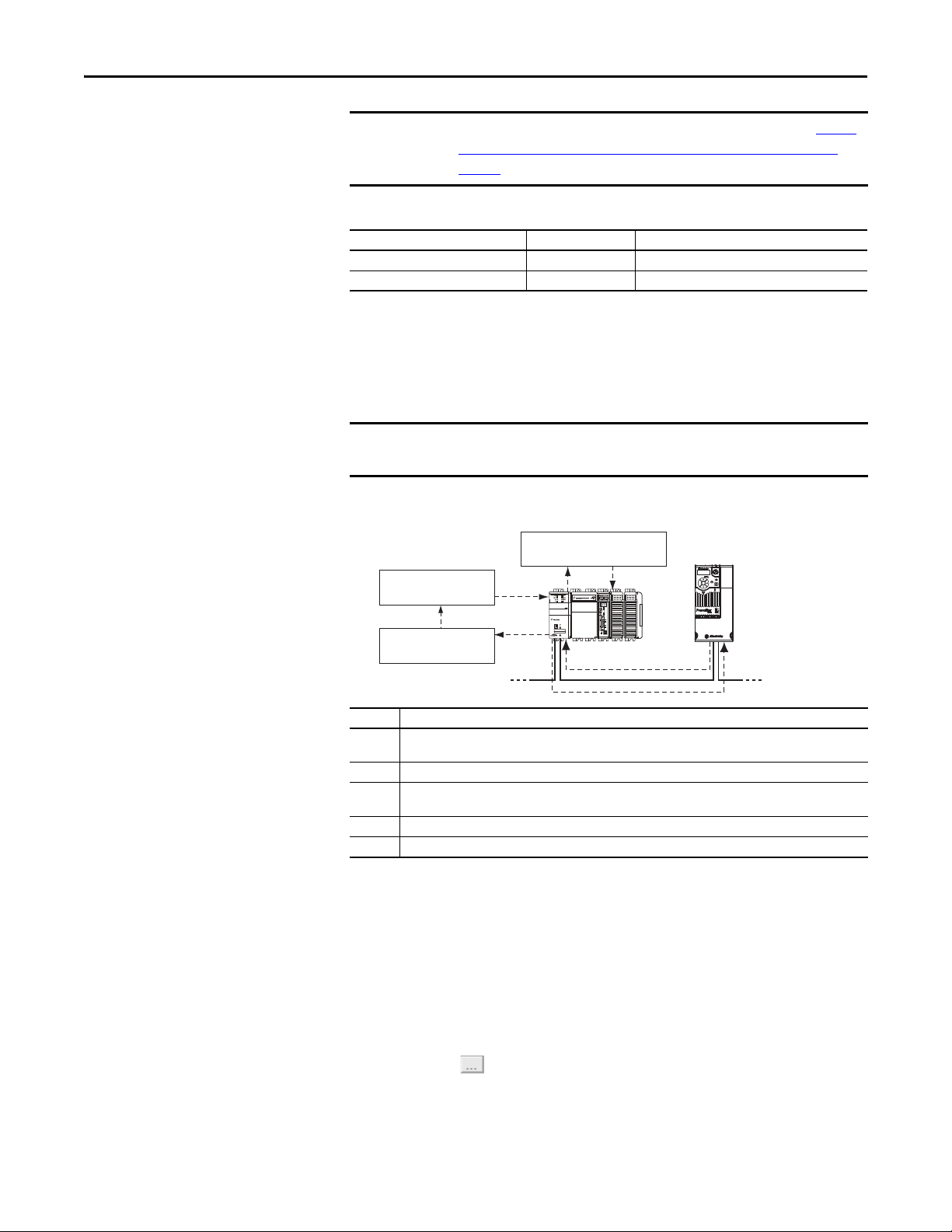
Chapter 6 Using Explicit Messaging
IMPORTANT
IMPORTANT
Esc
Sel
Complete Explicit
Message
Retrieve Explicit
Message Response
Set up and send Explicit
Message Request
Network Network
TIP
PowerFlex 520-series drives have explicit messaging limitations. See Explicit
Messaging Class Code Compatibility with PowerFlex 520-series Drives on
page 74 for more information.
Explicit Messaging Class Code Compatibility with PowerFlex 520-series Drives
EtherNet/IP Object Class Code Compatibility Explicit Messaging Function
Parameter Object 0x0F Yes Single parameter reads/write
DPI Parameter Object 0x93 Yes Single and scattered parameter reads/write
Performing Explicit Messaging
There are five basic events in the Explicit Messaging process. The details of each
step will vary depending on the type of controller being used. See the
documentation for your controller.
There must be a request message and a response message for all Explicit
Messages, whether you are reading or writing data.
Explicit Messaging Process
➊
➎
00:00:BC:2E:69:F6
1 (Front)1 (Front)1 (Front)
2 (Rear)
➍
Event Description
➊ You format the required data and set up the ladder logic program to send an Explicit Message request to the
scanner or bridge module (download).
➋ The scanner or bridge module transmits the Explicit Message Request to the slave device over the network.
➌ The slave device transmits the Explicit Message Response back to the scanner. The data is stored in the
scanner buffer.
➍ The controller retrieves the Explicit Message Response from the scanner’s buffer (upload).
➎ The Explicit Message is complete.
➋
➌
For information on the maximum number of Explicit Messages that can be
executed at a time, see the documentation for the bridge or scanner and/or
controller that is being used.
CompactLogix Controller Examples
74 Rockwell Automation Publication 520COM-UM003A-EN-E - June 2013
To display the Message Configuration screen in RSLogix 5000 or Logix Designer,
add a message instruction (MSG), create a new tag for the message
(Properties: Base tag type, MESSAGE data type, controller scope), and click the
button in the message instruction.
Page 75

Using Explicit Messaging Chapter 6
IMPORTANT
Execute_Single_Read_Message
Message
Message Control Single_Read_Message
MSG
EN
DN
ER
For supported classes, instances, and attributes, see EtherNet/IP Objects on
page 129.
The explicit messaging examples in this section can be performed using any
software version of RSLogix 5000 or Logix Designer.
The read and write messaging examples in this section are for Device
parameters which use Class Code 0x93.
The Message Configuration also has a supported Service Type of “Parameter
Read” which is Class code 0x0F, Parameter Object.
Example Ladder Logic Program to Read a Single Parameter
A Get Attribute Single message is used to read a single parameter. This
CompactLogix controller read message example reads the value of the 16-bit
parameter b003 [Output Current] in a PowerFlex 525 drive.
Example Controller Tags to Read a Single Parameter
Operation Controller Tags for Single Read Message Data Types
XIC Execute_Single_Read_Message BOOL
MSG Single_Read_Message MESSAGE
Example Ladder Logic to Read a Single Parameter
Formatting a Message to Read a Single Parameter
Get Attribute Single Message Configuration Screens
Rockwell Automation Publication 520COM-UM003A-EN-E - June 2013 75
Page 76

Chapter 6 Using Explicit Messaging
Execute_Single_Write_Message
Message
Message Control Single_Write_Message
MSG
EN
DN
ER
The following table identifies the data that is required in each box to configure a
CompactLogix controller message to read a single parameter.
Configuration Tab Example Value Description
Message Type
Service Type
Service Code
(1)
(1)
Class
Instance
Attribute
Source Element
Source Length
Destination
Communication Tab Example Value Description
(2)
Path
Tag Ta b Example Value Description
Name Single_Read_Message The name for the message.
(1) The default setting for Service Type is “Custom,” enabling entry of a Ser vice Code not available from the Service Type pull-down
menu. When choosing a Service Type other than “Custom” from the pull-down menu, an appropriate Hex. value is automatically
assigned to the Service Code box which is dimmed (unavailable).
(2) Click Browse to find the path, or type in the name of the device listed in the I/O Configuration folder (for this example,
PowerF lex_52 X_Driv e).
(3) See Explicit Messaging Class Code Compatibility with PowerFlex 520-series Drives on page 74 for limitations of PowerFlex 520-series
drives when using DPI Parameter Object Class code 0x93 for explicit messaging.
(4) In this example, Output Current is a 16-bit parameter requiring the Data Type field to be set to “INT” when creating the controller
tag. See the drive documentation to determine the size of the parameter and its data type.
CIP Generic
Get Attribute Single
e (Hex.)
(3)
93
3 (Dec.)
9 (Hex.)
–
0 bytes
Output_Current
(4)
Used to access the DPI Parameter Object in the adapter.
This service is used to read a parameter value.
Code for the requested service.
Class ID for the DPI Parameter Object.
Instance number is the same as parameter number.
Attribute number for the Parameter Value attribute.
Leave blank (not applicable).
Number of bytes of service data to be sent in the message.
The tag where the data that is read is stored.
PowerFlex_52X_Drive The path is the route that the message will follow.
Example Ladder Logic Program to Write a Single Parameter
A Set Attribute Single message is used to write to a single parameter. This
CompactLogix controller write message example writes a value to the 16-bit
parameter P041 [Accel Time 1] in a PowerFlex 525 drive.
Example Controller Tags to Write a Single Parameter
Operation Controller Tags for Single Write Message Data Types
XIC Execute_Single_Write_Message BOOL
MSG Single_Write_Message MESSAGE
Example Ladder Logic to Write a Single Parameter
76 Rockwell Automation Publication 520COM-UM003A-EN-E - June 2013
Page 77

Using Explicit Messaging Chapter 6
Formatting a Message to Write a Single Parameter
Set Attribute Single Message Configuration Screens
The following table identifies the data that is required in each box to configure a
CompactLogix controller message to write a single parameter.
Configuration Tab Example Value Description
Message Type
Service Type
(1)
Service Code
Class
(2)
Instance
(3)
Attribute
Source Element
Source Length
Destination
(1)
CIP Generic
Get Attribute Single
10 (Hex.)
(5)
93
41 (Dec.)
9
Accel_Time_1
(6)
2 bytes
–
Communication Tab Example Value Description
Path
(4)
PowerFlex_52X_Drive The path is the route that the message will follow.
Tag Ta b Example Value Description
Name Single_Write_Message The name for the message.
(1) The default setting for Service Type is “Custom,” enabling entry of a Ser vice Code not available from the Service Type pull-down
menu. When choosing a Service Type other than “Custom” from the pull-down menu, an appropriate Hex. value is automatically
assigned to the Service Code box which is dimmed (unavailable).
(2) The instance is the parameter number in the drive.
(3) Setting the Attribute value to “9” will write the parameter value to the drive’s Non-Volatile Storage (EEPROM) memory, so the
parameter value will remain even after the drive is power c ycled. Important: When set t o “9,” be very cau tious as th e EEPROM may
quickly exceed its life cycle and cause the drive to malfunction. Important: If you need to make frequent parameter changes using
Explicit Messages, set parameter C121 [Comm Write Mode] to 1 “RAM only”.
(4) Click Browse to find the path, or type in the name of the device listed in the I/O Configuration folder (for this example,
PowerF lex_52 X_Driv e).
(5) See Explicit Messaging Class Code Compatibility with PowerFlex 520-series Drives on page 74 for limitations of PowerFlex 520-series
drives when using DPI Parameter Object Class code 0x93 for explicit messaging.
(6) In this example, Accel Time 1 is a 16-bit parameter requiring the Data Type field to be set to “INT” when creating the controller tag.
Also, the Source Length field on the Message Configuration screen must correspond to th e selected Data Type in bytes (for example,
2 bytes for an INT). See the drive documentation to determine the size of the p arameter and its data type.
Used to access the DPI Parameter Object in the adapter.
This service is used to read a parameter value.
Code for the requested service.
Class ID for the DPI Parameter Object.
Instance number is the same as parameter number.
Attribute number for the Parameter Value attribute.
Name of the tag for any service data to be sent from the scanner
or bridge to the drive.
Number of bytes of service data to be sent in the message.
Leave blank (not applicable).
Rockwell Automation Publication 520COM-UM003A-EN-E - June 2013 77
Page 78

Chapter 6 Using Explicit Messaging
Explanation of Request and Response Data for Read/Write Multiple Messaging
The data structures in Data Structures for Scattered Read Messages on page 79
and Data Structures for Scattered Write Messages
and can accommodate up to 64 parameters in a single message. In the Response
Message, a parameter number with Bit 15 set indicates that the associated
parameter value field contains an error code (parameter number in response data
will be negative).
The PowerFlex 525 Adjustable Frequency AC Drive User Manual, publication
520-UM001
lists the data type for each parameter.
on page 80 use 16-bit words
78 Rockwell Automation Publication 520COM-UM003A-EN-E - June 2013
Page 79

Using Explicit Messaging Chapter 6
Data Structures for Scattered Read Messages
Request (Source Data) Response (Destination Data)
INT 0 Parameter Number INT 0 Parameter Number
1Pad 1Parameter Value
2 Parameter Number 2 Parameter Number
3Pad 3Parameter Value
4 Parameter Number 4 Parameter Number
5Pad 5Parameter Value
6 Parameter Number 6 Parameter Number
7Pad 7Parameter Value
8 Parameter Number 8 Parameter Number
9Pad 9Parameter Value
10 Parameter Number 10 Parameter Number
11 Pad 11 Parameter Value
12 Parameter Number 12 Parameter Number
13 Pad 13 Parameter Value
14 Parameter Number 14 Parameter Number
15 Pad 15 Parameter Value
16 Parameter Number 16 Parameter Number
17 Pad 17 Parameter Value
18 Parameter Number 18 Parameter Number
19 Pad 19 Parameter Value
20 Parameter Number 20 Parameter Number
21 Pad 21 Parameter Value
22 Parameter Number 22 Parameter Number
23 Pad 23 Parameter Value
24 Parameter Number 24 Parameter Number
25 Pad 25 Parameter Value
26 Parameter Number 26 Parameter Number
27 Pad 27 Parameter Value
28 Parameter Number 28 Parameter Number
29 Pad 29 Parameter Value
30 Parameter Number 30 Parameter Number
31 Pad 31 Parameter Value
32 Parameter Number 32 Parameter Number
33 Pad 33 Parameter Value
34 Parameter Number 34 Parameter Number
35 Pad 35 Parameter Value
...
62 Parameter Number 62 Parameter Number
63 Pad 63 Parameter Value
...
...
...
Rockwell Automation Publication 520COM-UM003A-EN-E - June 2013 79
Page 80

Chapter 6 Using Explicit Messaging
Data Structures for Scattered Write Messages
Request (Source Data) Response (Destination Data)
INT 0 Parameter Number INT 0 Parameter Number
1 Parameter Value 1 Pad
2 Parameter Number 2 Parameter Number
3 Parameter Value 3 Pad
4 Parameter Number 4 Parameter Number
5 Parameter Value 5 Pad
6 Parameter Number 6 Parameter Number
7 Parameter Value 7 Pad
8 Parameter Number 8 Parameter Number
9 Parameter Value 9 Pad
10 Parameter Number 10 Parameter Number
11 Parameter Value 11 Pad
12 Parameter Number 12 Parameter Number
13 Parameter Value 13 Pad
14 Parameter Number 14 Parameter Number
15 Parameter Value 15 Pad
16 Parameter Number 16 Parameter Number
17 Parameter Value 17 Pad
18 Parameter Number 18 Parameter Number
19 Parameter Value 19 Pad
20 Parameter Number 20 Parameter Number
21 Parameter Value 21 Pad
22 Parameter Number 22 Parameter Number
23 Parameter Value 23 Pad
24 Parameter Number 24 Parameter Number
25 Parameter Value 25 Pad
26 Parameter Number 26 Parameter Number
27 Parameter Value 27 Pad
28 Parameter Number 28 Parameter Number
29 Parameter Value 29 Pad
30 Parameter Number 30 Parameter Number
31 Parameter Value 31 Pad
32 Parameter Number 32 Parameter Number
33 Parameter Value 33 Pad
34 Parameter Number 34 Parameter Number
35 Parameter Value 35 Pad
...
62 Parameter Number 62 Parameter Number
63 Parameter Value 63 Pad
...
...
...
80 Rockwell Automation Publication 520COM-UM003A-EN-E - June 2013
Page 81

Using Explicit Messaging Chapter 6
Execute_Scattered_Read_Message
Message
Message Control Scattered_Read_Message
MSG
EN
DN
ER
Example Ladder Logic Program to Read Multiple Parameters
A Scattered Read message is used to read the values of multiple parameters. This
CompactLogix controller read message example reads the values of these five 16bit parameters in a PowerFlex 525 drive:
• Host parameter b001[Output Freq]
• Host parameter b003 [Output Current]
• Host parameter b004 [Output Voltage]
• Host parameter b005 [DC Bus Voltage]
• Host parameter b017 [Output Power]
See DPI Parameter Object
on page 145 (Class code 0x93) for parameter
numbering.
Example Controller Tags to Read Multiple Parameters
Operation Controller Tags for Scattered Read Message Data Types
XIC Execute_Scattered_Read_Message BOOL
MSG Scattered_Read_Message MESSAGE
Example Ladder Logic to Read Multiple Parameters
Formatting a Message to Read Multiple Parameters
Scattered Read Message Configuration Screens
Rockwell Automation Publication 520COM-UM003A-EN-E - June 2013 81
Page 82

Chapter 6 Using Explicit Messaging
The following table identifies the data that is required in each box to configure a
CompactLogix controller message to read multiple parameters.
Configuration Tab Example Value Description
Message Type
Service Type
Service Code
Class
Instance
Attribute
Source Element
Source Length
Destination
Communication Tab Example Value Description
Path
Tag Ta b Example Value Description
Name Scattered_Read_Message The name for the message.
(1) The default setting for Service Type is “Custom,” enabling entry of a Ser vice Code not available from the Service Type pull-down
(2) Click Browse to find the path, or type in the name of the device listed in the I/O Configuration folder (for this example,
(3) See Explicit Messaging Class Code Compatibility with PowerFlex 520-series Drives on page 74 for limitations of PowerFlex 520-series
(4) In this example, we are reading five 16-bit parameters. Each parameter being read requires two contiguous INT registers. Therefore,
(5) The controller tag for “Scattered_Read_Response” must be the same size as the controller tag for “Scattered_Read_Request” (for
(1)
(1)
(2)
menu. When choosing a Service Type other than “Custom” from the pull-down menu, an appropriate Hex. value is automatically
assigned to the Service Code box which is dimmed (unavailable).
PowerF lex_52 X_Driv e).
drives when using DPI Parameter Object Class code 0x93 for explicit messaging.
a controller tag was created with its Data Type field set to “INT[10].” Also, the Source Length field on the Message Configuration
screen must correspond to the selected Data Type in bytes (for this example, 20 bytes for an INT[10] array). Scattered read messages
always assume that every parameter be ing read is a16-bit parameter, regardless of its actual size. Maximum message length is 256
bytes which can read up to 6 4 parameters, regardless of their size.
this example, 20 bytes), but can be a different data type.
CIP Generic
Custom
0x32 (Hex.)
(3)
93
0 (Dec.)
0 (Hex.)
Scattered_Read_Request
(4)
20 bytes
Scattered_Read_Response
PowerFlex_52X_Drive The path is the route that the message will follow.
Used to access the DPI Parameter Object in the adapter.
Required for scattered messages.
Code for the requested service.
Class ID for the DPI Parameter Object.
Required for scattered messages.
Required for scattered messages.
(4)
Name of the tag for any service data to be sent from the scanner
or bridge to the drive.
(5)
Number of bytes of service data to be sent in the message.
The tag where the data that is read is stored.
Example Scattered Read Request Data
In this CompactLogix controller message example, we use the data structure in
Figure 101 in the source tag named Scattered Read Request to read these five 16bit parameters in a PowerFlex 525 drive:
• Host parameter b001 [Output Freq]
• Host parameter b003 [Output Current]
• Host parameter b004 [Output Voltage]
• Host parameter b005 [DC Bus Voltage]
• Host parameter b017 [Output Power]
See DPI Parameter Object
numbering.
Example Scattered Read Request Data
on page 145 (Class code 0x93) for parameter
82 Rockwell Automation Publication 520COM-UM003A-EN-E - June 2013
Page 83

Using Explicit Messaging Chapter 6
Example Scattered Read Response Data
The Scattered Read Request message reads the multiple parameters and returns
their values to the destination tag (Scattered_Read_Response). Example
Scattered Read Response Converted Data on page 83 shows the parameter
values.
Example Scattered Read Response Converted Data
In this message example, the parameters have the following values:
PowerFlex 525 Drive Parameters Read Value
b001 [Output Freq] 50.00 Hz
b003 [Output Current] 0.01 Amp (No load)
b004 [Output Voltage] 179.6V AC
b005 [DC Bus Voltage] 349V DC
b017 [Output Power] 0 kW (No load)
Example Ladder Logic Program to Write Multiple Parameters
A Scattered Write message is used to write to multiple parameters. This
CompactLogix controller write message example writes the following values to
these five 16-bit parameters in a PowerFlex 525 drive:
PowerFlex 525 Drive Parameters Write Value
A442 [Accel Time 2] 11.10 Sec
A443 [Decel time 2] 22.20 Sec
A415 [Preset Freq 5] 33.30 Hz
A416 [Preset Freq 6] 44.40 Hz
A417 [Preset Freq 7] 55.50 Hz
Example Controller Tags to Write Multiple Parameters
Operation Controller Tags for Scattered Write Message Data Types
XIC Execute_Scattered_Write_Message BOOL
MSG Scattered_Write_Message MESSAGE
Rockwell Automation Publication 520COM-UM003A-EN-E - June 2013 83
Page 84

Chapter 6 Using Explicit Messaging
IMPORTANT
Execute_Scattered_Write_Message
Message
Message Control Scattered_Write_Message
MSG
EN
DN
ER
Example Ladder Logic to Write Multiple Parameters
This example scattered write message writes to NVS. Over time, continuous
writes will exceed the EEPROM life cycle and cause the drive to malfunction.
If you need to make frequent parameter changes using Explicit Messages, set
Host parameter C121 [Comm Write Mode] to 1 “RAM only”.
Formatting a Message to Write Multiple Parameters
Scattered Write Multiple Message Configuration Screens
84 Rockwell Automation Publication 520COM-UM003A-EN-E - June 2013
The following table identifies the data that is required in each box to configure a
CompactLogix controller message to write multiple parameters.
Configuration Tab Example Value Description
Message Type
Service Type
Service Code
Class
Instance
Attribute
Source Element
Source Length
Destination
Communication Tab Example Value Description
Path
Tag Ta b Example Value Description
Name Scattered_Write_Message The name for the message.
(1)
(1)
(2)
CIP Generic
Custom
0x34 (Hex.)
(4)
93
0 (Dec.)
0 (Hex.)
Scattered_Write_Request
(5)
20 bytes
Scattered_Write_Response
Used to access the DPI Parameter Object in the adapter.
Required for scattered messages.
Code for the requested service.
Class ID for the DPI Parameter Object.
Required for scattered messages.
Required for scattered messages.
(5)
Name of the tag for any service data to be sent from the scanner
or bridge to the drive.
(6)
Number of bytes of service data to be sent in the message.
The tag where the data that is read is stored.
(3)
PowerFlex_52X_Drive The path is the route that the message will follow.
Page 85

Using Explicit Messaging Chapter 6
(1) The default setting for Service Type is “Custom,” enabling entry of a Ser vice Code not available from the Service Type pull-down
menu. When choosing a Service Type other than “Custom” from the pull-down menu, an appropriate Hex. value is automatically
assigned to the Service Code box which is dimmed (unavailable).
(2) Scattered writes always write parameter values to the drive’s Non-Volatile Storage (EEPROM) memory, so these values will remain
even after the drive is power cycled. Important: Be very cautious as the EEPROM may quickly exceed its life cycle and cause the
drive to malfunction. Important: If you need to make frequent parameter changes using Explicit Messages, set parameter C121
[Comm Write Mode] to 1 “RAM only”.
(3) Click Browse to find the path, or type in the name of the device listed in the I/O Configuration folder (for this example,
PowerF lex_52 X_Driv e).
(4) See Explicit Messaging Class Code Compatibility with PowerFlex 520-series Drives
drives when using DPI Parameter Object Class code 0x93 for explicit messaging.
(5) In this example, we are writing to five 16-bit parameters. Each parameter being written to requires two contiguous INT registers.
Also, the Source Length field on the Message Configuration screen must correspond to the selected Data Type in bytes (for this
example, 20 bytes for an array of ten INTs). Scattered write messages always assume that every parameter being written to is a 16-
bit parameter, regardless of its actual size. Maximum message length is 256 bytes which can write up to 64 parameters, regardless
of their size. For parameter numbering, see DPI Parameter Object
(6) The controller tag for “Scattered_Write_Response” must be the same size as the controller tag for “Scattered_Write_Request” (for
this example, 20 bytes). An array of INTs is suggested to be able to read any error codes that are returned.
on page 145 (Class code 0x93).
on page 74 for limitations of PowerFlex 520-series
Example Scattered Write Request Data
In this message example, we use the source tag (Scattered_Write_Request) to
write new values to these 16-bit parameters:
PowerFlex 525 Drive Parameters Write Value
A442 [Accel Time 2] 11.10 Sec
A443 [Decel time 2] 22.20 Sec
A415 [Preset Freq 5] 33.30 Hz
A416 [Preset Freq 6] 44.40 Hz
A417 [Preset Freq 7] 55.50 Hz
Example Scattered Write Request Converted Data
on page 85 shows the
parameter values.
Example Scattered Write Request Converted Data
Example Scattered Write Response Data
The results of the message appear in the destination tag named
Scattered_Write_Response (Example Scattered Write Response Data
page 86). Values of “0” indicate no errors occurred.
on
Rockwell Automation Publication 520COM-UM003A-EN-E - June 2013 85
Page 86

Chapter 6 Using Explicit Messaging
Example Scattered Write Response Data
86 Rockwell Automation Publication 520COM-UM003A-EN-E - June 2013
Page 87

Chapter 7
Using Multi-Drive Mode
This chapter provides instructions on how to configure a CompactLogix
controller to use the PowerFlex 520-series drive in Multi-drive mode.
Top ic Pa ge
Single-Drive Mode vs. Multi-Drive Mode
System Wiring 89
Understanding the I/O Image 90
Configuring the RS-485 Network 91
Using Multi-Drive Add-On Profile 91
Multi-Drive Ladder Logic Program for Generic Profile 102
CompactLogix Controller Example Using Generic Profile 103
Multi-Drive Mode Explicit Messaging 111
Additional Information 112
87
Single-Drive Mode vs.
Multi-Drive Mode
ATT EN TI ON : On PowerFlex 525 drives, support for multi-drive mode using the
25-COMM-E2P Dual-Port adapter is only available on firmware revision 1.004
and later.
ATT EN TI ON : Risk of injury or equipment damage exists. The examples in this
publication are intended solely for purposes of example. There are many
variables and requirements with any application. Rockwell Automation, Inc.
does not assume responsibility or liability (to include intellectual property
liability) for actual use of the examples shown in this publication.
Single-drive mode is a typical network installation, where a single EtherNet/IP
node consists of a single drive with an EtherNet/IP adapter.
Rockwell Automation Publication 520COM-UM003A-EN-E - June 2013 87
Page 88

Chapter 7 Using Multi-Drive Mode
IMPORTANT
Esc
Sel
Esc
Sel
Esc
Sel
One drive per node
EtherNet/IP
PowerFlex 525 with
25-COMM-E2P
PowerFlex 525 with
25-COMM-E2P
PowerFlex 525 with
25-COMM-E2P
Esc
Sel
Up to 5 drives per node
EtherNet/IP
Up to four daisy-chained PowerFlex drives
(PowerFlex 4M s hown)
RS-485 cable
PowerFlex 525
with
25-COMM-E2P
as master drive
AK-U0-RJ45-TB2P connector with
terminating resistor (120 Ω)
AK-U0-RJ45-TB2P connector with
terminating resistor (120 Ω)
AK-U0-RJ45-TB2P
Single-Drive Mode Example for Network
Multi-drive mode is an alternative to the typical network installation, where a
single EtherNet/IP node can consist of one to five drives (see Multi-Drive Mode
Example for Network on page 88). The first drive must be a PowerFlex 520-series
drive. The remaining drives can be any PowerFlex drive which supports Multidrive mode.
For the examples in the chapter, we will use the PowerFlex 525 as a master
drive with four daisy-chained PowerFlex 4M drives.
88 Rockwell Automation Publication 520COM-UM003A-EN-E - June 2013
Multi-Drive Mode Example for Network
Benefits of Multi-drive mode include:
• Lower hardware costs. No need to purchase additional communication
adapters for daisy-chained drives.
• Reduces the network node count. For example, in Single-drive mode 30
drives would consume 30 nodes. In Multi-drive mode, 30 drives can be
connected in 6 nodes.
• Controller can control, monitor, and read/write parameters for all five
drives.
The trade-offs of Multi-drive mode include:
• If the PowerFlex 520-series drive with Dual-port EtherNet/IP adapter is
powered down, then communications with the daisy-chained drives is
disrupted and the drives will take the appropriate communications loss
action set in each drive.
Page 89

Using Multi-Drive Mode Chapter 7
To PowerFlex 525 with
25-COMM-E2P
To Drive #2 To Drive #3 To Drive #4 To Drive #5
120 Ω, 1/4 W
resistor
120 Ω, 1/4 W
resisto r
• Communications throughput to the daisy-chained drives will be slower
than if each drive was a separate node on EtherNet/IP (Single-drive
mode). This is because the Dual-port EtherNet/IP adapter must take the
EtherNet/IP data for the other drives and sequentially send the respective
data to each drive over RS-485. The approximate additional throughput
time for Logic Command/Reference to be transmitted and received by
each drive is:
System Wiring
Drive Additional Throughput Time
versus Single-Drive Mode
PowerFlex 525 0 ms
PowerFlex 525 plus 1 drive +24 ms
PowerFlex 525 plus 2 drives +48 ms
PowerFlex 525 plus 3 drives +72 ms
PowerFlex 525 plus 4 drives +96 ms
• Since the RS-485 ports are used for daisy-chaining the drives, there is no
connection for a peripheral device such as a HIM or USB converter
module (1203-USB). DSI Splitter cables cannot be used to add a second
connection for a peripheral device.
To daisy-chain the drives to the PowerFlex 525, the AK-U0-RJ45-TB2P terminal
block connector can be used for easy installation.
The wiring diagram for using AK-U0-RJ45-TB2P terminal block connectors is
shown below.
The AK-U0-RJ45-TB2P comes with (5) terminal block connectors and (2)
terminating resistors.
Rockwell Automation Publication 520COM-UM003A-EN-E - June 2013 89
Page 90
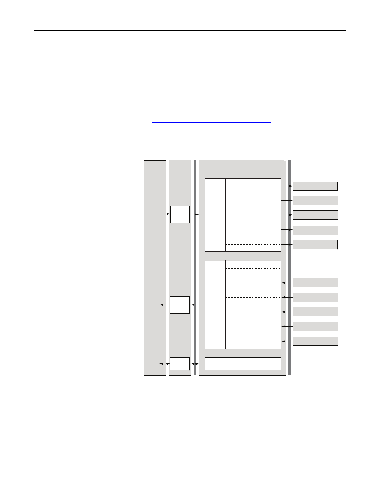
Chapter 7 Using Multi-Drive Mode
Understanding the I/O Image
The terms input and output are defined from the scanner’s point of view.
Therefore, Output I/O is data that is output from the scanner and consumed by
the EtherNet/IP adapter. Input I/O is status data that is produced by the adapter
and consumed as input by the scanner.
The I/O image table will vary based on the configuration of Host parameters
C169 [MultiDrv Sel] and C175 [DSI I/O Cfg]. The image table always uses
consecutive words starting at word 0.
The Multi-Drive Example of I/O Image
on page 90 is an illustration of the
Multi-drive I/O image with 16-bit words.
Multi-Drive Example of I/O Image
Controller
Scanner
Output
Image
(Write)
EtherNet/IP
Drive 0
Drive 1
Drive 2
Drive 3
Drive 4
Adapter
Wor d and I /O
Logic CommandWord 0
ReferenceWord 1
Logic CommandWord 2
ReferenceWord 3
Logic CommandWord 4
ReferenceWord 5
Logic CommandWord 6
ReferenceWord 7
Logic CommandWord 8
ReferenceWord 9
DSI
PowerFlex Drive 0
PowerFlex Drive 1
PowerFlex Drive 2
PowerFlex Drive 3
PowerFlex Drive 4
(1)
Message
Buer
Padword
PadwordWord 1
Logic StatusWord 2
FeedbackWord 3
Logic StatusWord 4
FeedbackWord 5
Logic StatusWord 6
FeedbackWord 7
Logic StatusWord 8
FeedbackWord 9
Logic StatusWord 10
FeedbackWord 11
PowerFlex Drive 0
PowerFlex Drive 1
PowerFlex Drive 2
PowerFlex Drive 3
PowerFlex Drive 4
Word 0
Drive 0
Input
Image
(Read)
Message
Handler
(1) Padwords only apply when using the generic profile. Padwords are not used when using the full-featured drive Add-On-Profile.
Drive 1
Drive 2
Drive 3
Drive 4
Note: If a daisy-chained drive is disconnected from the RS-485 (DSI) network
or powered down, the Logic Status and Feedback words for the affected drive will
be set to 0.
90 Rockwell Automation Publication 520COM-UM003A-EN-E - June 2013
Page 91

Using Multi-Drive Mode Chapter 7
IMPORTANT
IMPORTANT
Configuring the RS-485 Network
The following parameters must be set in the daisy-chained PowerFlex 4M drives
and not in the master drive:
Parame ter Value
P106 [Start Source] 5 “Comm Port”
P108 [Speed Reference] 5 “Comm Port”
C302 [Comm Data Rate] 4 “19.2K”
C303 [Comm Node Addr] 1...247 (must be unique)
C306 [Comm Format] 0 “RTU-8-N-1”
Note: The RS-485 Multi-drive network is fixed at 19.2K baud rate, 8 data bits,
no parity, and 1 stop bit.
Parameters [Comm Loss Action] and [Comm Loss Time] in the daisy-chained
drives are still used in Multi-drive mode. If the RS-485 cable is disconnected or
broken, the disconnected drive(s) will take the corresponding Comm Loss
Action(s). On the EtherNet/ IP side, Device parameters 23 [Comm Flt Action]
and 24 [Idle Flt Action] determine the action taken for ALL of the drives on the
Multi-drive node.
The following Multi-drive parameters must be set in the master PowerFlex 525
drive:
Parame ter Value
P046 [Start Source 1] 4 “Network Opt”
P047 [Speed Reference1] 4 “Network Opt”
C169 [MultiDrv Sel] 1 “Network Opt”
Note: Drive must be power cycled after setting this
parameter.
C171 [Drv 1 Addr]
C172 [Drv 2 Addr]
C173 [Drv 3 Addr]
C174 [Drv 4 Addr]
C175 [DSI I/O Cfg] 0 “Drive 0”
2
3
4
5
Note: Drive must be power cycled after setting this
parameter.
1 “Drive 0-1”
2 “Drive 0-2”
3 “Drive 0-3”
4 “Drive 0-4”
Note: Drive must be power cycled after setting this
parameter.
Parameters can be set using a DSI peripheral (22-HIM-A3 or 22-HIM-C2S) only
when Host parameter C169 [MultiDrv Sel] is set to 0 “Disabled”.
Using Multi-Drive Add-On Profile
Before using the Multi-drive Add-On Profile, ensure that you have completed the
following steps:
• The master and daisy-chained drives are powered, networked, and
configured. See System Wiring
Rockwell Automation Publication 520COM-UM003A-EN-E - June 2013 91
on page 89.
Page 92

Chapter 7 Using Multi-Drive Mode
TIP
• The RS-485 network is configured. See Configuring the RS-485 Network
on page 91.
• The controller has been added to the I/O configuration. See Adding the
Controller to the I/O Configuration on page 40.
Adding the Drive to the I/O Configuration
To transmit data between the controller and the drive, you must add the drive as a
child device to the parent controller. In this example, RSLogix 5000 software
version 20 is used with drive Add-On Profile version 1.02 or later.
1. In the treeview, right-click on the icon and select New
Module… to display the Select Module window. Expand the Drives group
to display all of the available drives with their communication adapters.
If the PowerFlex drive is not shown, go to www.ab.com/support/
abdrives/webupdate and download the latest drive Add-On Profile.
2. In the Select Module Type window, select the drive and its connected
adapter from the list. For this example, we selected “Multi-Drive-25COMM-E2P.” Then click Create. The drive’s New Module window
appears.
92 Rockwell Automation Publication 520COM-UM003A-EN-E - June 2013
Page 93

Using Multi-Drive Mode Chapter 7
3. On the General tab, edit the following data about the drive:
Box Setting
Name A name to identify the drive.
Description Optional – description of the drive/adapter.
IP Address The IP address of the adapter.
4. On the New Module window in the Module Definition section, click
Change… to launch the Module Definition window and begin the drive
configuration process.
Rockwell Automation Publication 520COM-UM003A-EN-E - June 2013 93
Page 94

Chapter 7 Using Multi-Drive Mode
TIP
IMPORTANT
5. In the Module Definition window, edit the following information for the
master drive:
You may create a database from a network accessible drive using the
Create Database... button (Recommended).
Box Setting
Drive Rating The voltage and current rating of the drive. If the drive rating is not listed, the drive
Revision The major and minor revision of the firmware (database) in the drive. If the drive’s major
Electronic Keying Compatible Module. The “Compatible Module” setting for Electronic Keying ensures the
database is not installed on your computer. To get the drive rating, use the Create
Database…, or Web Update… button described above.
and minor revision is not available, the drive database is not installed on your computer. To
get the correct database revision, use one of the following buttons at the bottom left of the
Module Definition window:
•Create Database… Creates a database from an online network multi-drive. Clicking
this button displays an RSLinx RSWho window. Browse to the online drive (PowerFlex
525), select it, and click OK. The database will be uploaded and stored on the computer.
Thereafter, close the Module Definition window and then re-open it to display the new
revisio n.
• Web Update… When a drive is not available online, opens the Allen-Bradley Drives
Web Updates web site to download a specific database file. After downloading the file,
close the Module Definition window and then re-open it to display the new revision.
physical module is consistent with the software configu ration before the controller and
bridge make a connection. Therefore, ensure that you have set the correct revision in this
window. See the online Help for additional information on this and other Electronic Keying
settings. If keying is not required, select “Disable Keying.” Drives do not require keying, and
so “Disable Keying” is recommended.
On the Module Definition window, notice that the automatically-assigned
controller tags Drive Status, Feedback, Logic Command, and Reference
are always used.
The Velocity/Positioning mode select is in the lower right of the
window when the master PowerFlex 525 drive is selected.
94 Rockwell Automation Publication 520COM-UM003A-EN-E - June 2013
Page 95
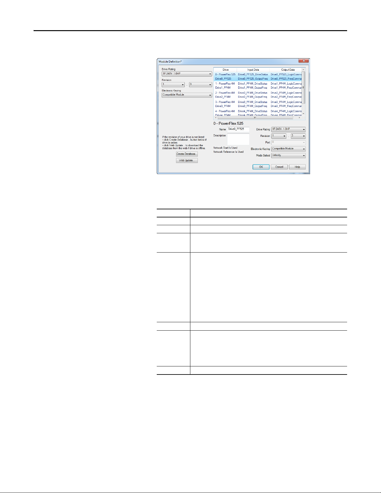
Using Multi-Drive Mode Chapter 7
TIP
6. Click Add to select and define each daisy-chained drive:
You may create a database from a network accessible drive using the
Create Database... button (Recommended).
Box Setting
Name A name to identify an individual drive.
Description Optional – description of an individual drive.
Drive Rating The voltage and current rating of the drive. If the drive rating is not listed, the drive
Revision The major and minor revision of the firmware (database) in the drive. If the drive’s major
Port Por t assignment for e ach drive
Electronic Keying Compatible Module. The “Compatible Module” setting for Electronic Keying ensures the
Mode Select Sets the I/O configuration to either Velocity or Position mode.
database is not installed on your computer. To get the drive rating, use the Create
Database…, or Web Update… button described above.
and minor revision is not available, the drive database is not installed on your computer. To
get the correct database revision, use one of the following buttons at the bottom left of the
Module Definition window:
•Create Database… Creates a database from an online network multi-drive. Clicking
this button displays an RSLinx RSWho window. Browse to the online drive (PowerFlex
525), select it, and click OK. The database will be uploaded and stored on the computer.
Thereafter, close the Module Definition window and then re-open it to display the new
revisio n.
• Web Update… When a drive is not available online, opens the Allen-Bradley Drives
Web Updates web site to download a specific database file. After downloading the file,
close the Module Definition window and then re-open it to display the new revision.
physical module is consistent with the software configu ration before the controller and
bridge make a connection. Therefore, ensure that you have set the correct revision in this
window. See the online Help for additional information on this and other Electronic Keying
settings. If keying is not required, select “Disable Keying.” Drives do not require keying, and
so “Disable Keying” is recommended.
7. Click OK on the Module Definition window to save the drive
configuration and close the window. The drive’s New Module window
reappears.
Rockwell Automation Publication 520COM-UM003A-EN-E - June 2013 95
Page 96

Chapter 7 Using Multi-Drive Mode
8. On the New Module window, click the Connection tab.
9. In the “Requested Packet Interval (RPI)” box, set the value to 2.0
milliseconds or greater. This value determines the maximum interval that a
controller should use to move data to and from the adapter. To conserve
bandwidth, use higher values for communicating with low priority devices.
The “Inhibit Module” box, when checked, inhibits the module from
communicating with the RSLogix 5000 or Logix Designer project. When
the “Major Fault On…” box is checked, a major controller fault will occur
when the module’s connection fails while the controller is in the Run
Mode. For this example, leave the “Inhibit Module” and “Major Fault
On…” boxes unchecked.
The “Use Unicast Connection over EtherNet/IP” box is checked by
default. This is the recommended setting. When this box is unchecked, the
adapter will send multicast messages on the I/O connection. In this case,
the adapter and the EtherNet/IP bridge must be on the same subnet.
10. Click OK on the New Module window.
The new node (“PowerFlex 525-E2P-Multi PowerFlex_52X_Drive-Multi”
in this example) now appears under the icon in the I/O
Configuration folder. If you double-click on the Input Controller Tag (see
Controller Input Tags
Controller Output Tags
on page 97) and Output Controller Tag (see
on page 98), you will see that module-defined
data types and tags have been automatically created. Note that all tag
names are defined for each drive. After you save and download the
configuration, these tags allow you to access the Input and Output data of
the drives using the controller’s ladder logic.
96 Rockwell Automation Publication 520COM-UM003A-EN-E - June 2013
Page 97

Controller Input Tags
Using Multi-Drive Mode Chapter 7
Rockwell Automation Publication 520COM-UM003A-EN-E - June 2013 97
Page 98

Chapter 7 Using Multi-Drive Mode
Controller Output Tags
98 Rockwell Automation Publication 520COM-UM003A-EN-E - June 2013
Page 99

Using Multi-Drive Mode Chapter 7
TIP
Saving the I/O Configuration to the Controller
After adding the controller and drives to the I/O configuration, you must
download the configuration to the controller. You should also save the
configuration to a file on your computer.
1. In the RSLogix 5000 or Logix Designer window, select Communications
> Download. The Download dialog box appears.
If a message box reports that RSLogix 5000 or Logix Designer is unable
to go online, select Communications > Who Active to find your
controller in the Who Active screen. After finding and selecting the
controller, click Set Project Path to establish the path. If your
controller does not appear, you need to add or configure the EtherNet/
IP driver in RSLinx. See the RSLinx online help.
2. Click Download to download the configuration to the controller. When
the download is successfully completed, RSLogix 5000 or Logix Designer
goes into Online Mode and the I/O Not Responding box in the upper-left
of the window should be flashing green. Also, a yellow warning symbol
should be displayed on the I/O Configuration folder in the treeview and
on the drive profile.
3. If the controller was in Run Mode before clicking Download,
RSLogix 5000 or Logix Designer prompts you to change the controller
mode back to Remote Run. In this case, choose the appropriate mode for
your application. If the controller was in Program Mode before clicking
Download, this prompt will not appear.
4. Select File > Save. If this is the first time you saved the project, the Save As
dialog box appears. Navigate to a folder, type a file name, and click Save to
save the configuration to a file on your computer.
5. To ensure that the present project configuration values are saved,
RSLogix 5000 or Logix Designer prompts you to upload them. Click Ye s
to upload and save them.
Rockwell Automation Publication 520COM-UM003A-EN-E - June 2013 99
Page 100

Chapter 7 Using Multi-Drive Mode
TIP
Correlating the Drive with the Controller
You must now correlate the drive settings to the RSLogix 5000 or Logix Designer
project I/O settings so that they match. This requires loading the project I/O
settings into the drive.
1. In the treeview under I/O Configuration, right-click on the drive profile
(for this example “Multi-Drive-25-COMM-E2P
PowerFlex_52X_Drive_Multi”) and select Properties.
2. Select the Drive tab to begin the correlation process.
After the drive configuration data has been verified, the Drive tab will
display a request to synchronize the configuration with the drive. Click
Upl oad . The correlation process will continue. This may take several
minutes depending on the number and type of daisy-chained drives.
If the Differences Found Screen
on page 101 appears—which is typical,
click Download. This will download the project settings from the
controller to the drives. If Upl oad is clicked, the drive settings are
uploaded to the controller.
On subsequent connections to the drive (after the initial download),
select Upload.
100 Rockwell Automation Publication 520COM-UM003A-EN-E - June 2013
 Loading...