

Page 1
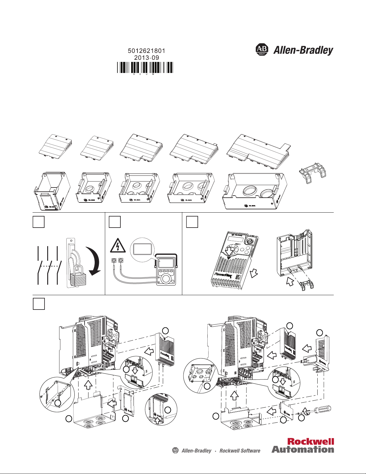
Installation Instructions
Retainer clip included
with all IP30/NEMA 1/
UL Type 1 Kits
Frame A – 25-JBAA Frame E – 25-JBAEFrame C – 25-JBAC Frame D – 25-JBADFrame B – 25-JBAB
1
L1 L2 L3
O
I
DC+ DC–
0V
0V
Wait three minutes after
shutdown for capacitors to
discharge to safe voltage levels.
Connect the Retainer Clip to the Control Module Front Cover
4
Install the Conduit Box
For Frame A For Frame B...D
a
b
c
d
e
a
b
c
d
e
f
f
g
PowerFlex 520-Series IP30/NEMA 1/UL Type 1 Kit Installation
Catalog Numbers: 25-JBAA, 25-JBAB, 25-JBAC, 25-JBAD, 25-JBAE
2 3
Publication 520-IN008B-EN-P - September 2013
Page 2
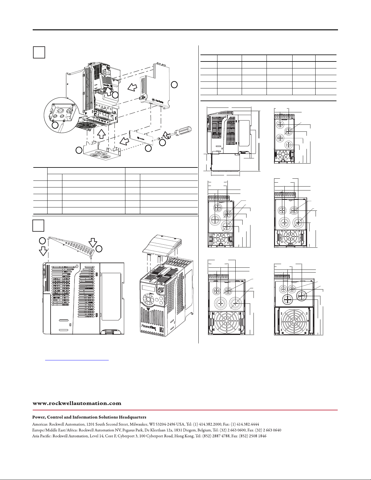
PowerFlex 520-Series IP30/NEMA 1/UL Type 1 Kit
5
Screw Size and Torque
Frame Conduit Box Conduit Box Front Bracket
Screws Screw Torque Screws Screw Torque
A 2 x M3 0.39...0.588 Nm (3.47...5.2 lb-in) 1 x M3 0.39...0.588 Nm (3.47...5.20 lb-in)
B 2 x M3 0.39...0.588 Nm (3.47...5.2 lb-in) 1 x M3 0.39...0.588 Nm (3.47...5.20 lb-in)
C 2 x M3 0.39...0.588 Nm (3.47...5.2 lb-in) 1 x M3 0.39...0.588 Nm (3.47... 5.20 lb-in)
D 2 x M3 0.39...0.588 Nm (3.47...5.2 lb-in) 1 x M3 0.39...0.588 Nm (3.47... 5.20 lb-in)
E 2 x M4 1.176...1.372 Nm (10.41...12.15 lb-in) 1 x M3 0.39...0.588 Nm (3.47...5.2 lb-in)
4
Install the Conduit Box (continued)
For Frame E
a
c
d
e
f
Attach the IP30/NEMA 1/UL Type 1 Cover
b
51.1 (2.01)
21.0 (0.82)
135.4 (5.33)
111.9 (4.41)
88.2 (3.47)
64.7 (2.55)
ø21.5 (ø0.85)
66.1 (2.60)
63.1 (2.48)
33.5 (1.32)
23.9 (0.94)
128.5 (5.06)
108.5 (4.27)
88.3 (3.48)
67.3 (2.65)
ø21.5 (ø0.85)
ø27.5 (ø1.08)
123.3 (4.85)
82.2 (3.24)
80.5 (3.17)
66.5 (2.62)
34.5 (1.36)
26.5 (1.04)
ø21.5 (ø0.85)
ø27.5 (ø1.08)
109.8 (4.32)
153.3 (6.04)
96.0 (3.78)
44.0 (1.73)
30.0 (1.18)
70.0 (2.76)
ø21.5 (ø0.85)
ø33.5 (ø1.32)
127.5 (5.02)
82.5 (3.25)
62.5 (2.46)
42.5 (1.67)
212.0 (8.35)
181.0 (7.13)
164.0 (6.46)
ø21.5 (ø0.85)
ø43.7 (ø1.72)
c
92.7 (3.65)
d
e
b
a
Frame a b c d e
A 172 (6.77) 234 (9.21) 110.8 (4.36) 67.0 (2.64) 6.0 (0.24)
B 172 (6.77) 233 (9.17) 103.4 (4.07) 38.0 (1.50) 6.1 (0.24)
C 184 (7.24) 270 (10.63) 102.7 (4.04) 35.0 (1.38) 6.0 (0.24)
D 212 (8.35) 310 (12.2 0) 105.6 (4.16) 35.0 (1.38) 6.0 (0.24)
E 27 9 (10.98) 365 (14.37) 117.8 (4 .64) 50.0 (1.97) 7.6 (0.3)
Note: Frames D and E cannot be mounted on DIN-rails.
Frame B – 25-JBAB
Frame A – 25-JBAA
Frame C – 25-JBAC
Frame D – 25-JBAD Frame E – 25-JBAE
Dimensions
All dimensions are in mm (in.)
a
b
U.S. Allen-Bradley Drives Technical Support - Tel: (1) 262.512.8176, Fax: (1) 262.512.2222, E-mail: support@drives.ra.rockwell.com
Online: http://www.ab.com/support/abdrives
Allen-Bradley, Rockwell Software, Rockwell Automation, PowerFlex, and TechConnect are trademarks of Rockwell Automation, Inc.
Trademarks not belonging to Rockwell Automation are property of their respective companies.
Publication 520-IN008B-EN-P - September 2013
Supersedes Publication 520-IN008A-EN-P - December 2012 Copyright © 2013 Rockwell Automation, Inc. All rights reserved.
 Loading...