

Page 1

User Manual
PowerFlex Digital DC Drive
PowerFlex DC Drive V1.006…6.002, PowerFlex DC Standalone Regulator V1.006…6.002
Page 2
Important User Information
IMPORTANT
Read this document and the documents listed in the additional resources section about installation, configuration, and
operation of this equipment before you install, configure, operate, or maintain this product. Users are required to
familiarize themselves with installation and wiring instructions in addition to requirements of all applicable codes, laws,
and standards.
Activities including installation, adjustments, putting into service, use, assembly, disassembly, and maintenance are required
to be carried out by suitably trained personnel in accordance with applicable code of practice.
If this equipment is used in a manner not specified by the manufacturer, the protection provided by the equipment may be
impaired.
In no event will Rockwell Automation, Inc. be responsible or liable for indirect or consequential damages resulting from the
use or application of this equipment.
The examples and diagrams in this manual are included solely for illustrative purposes. Because of the many variables and
requirements associated with any particular installation, Rockwell Automation, Inc. cannot assume responsibility or
liability for actual use based on the examples and diagrams.
No patent liability is assumed by Rockwell Automation, Inc. with respect to use of information, circuits, equipment, or
software described in this manual.
Reproduction of the contents of this manual, in whole or in part, without written permission of Rockwell Automation,
Inc., is prohibited.
Throughout this manual, when necessary, we use notes to make you aware of safety considerations.
WARNING: Identifies information about practices or circumstances that can cause an explosion in a hazardous environment,
which may lead to personal injury or death, property damage, or economic loss.
ATTENTION: Identifies information about practices or circumstances that can lead to personal injury or death, property
damage, or economic loss. Attentions help you identify a hazard, avoid a hazard, and recognize the consequence.
Identifies information that is critical for successful application and understanding of the product.
Labels may also be on or inside the equipment to provide specific precautions.
SHOCK HAZARD: Labels may be on or inside the equipment, for example, a drive or motor, to alert people that dangerous
voltage may be present.
BURN HAZARD: Labels may be on or inside the equipment, for example, a drive or motor, to alert people that surfaces may
reach dangerous temperatures.
ARC FLASH HAZARD: Labels may be on or inside the equipment, for example, a motor control center, to alert people to
potential Arc Flash. Arc Flash will cause severe injury or death. Wear proper Personal Protective Equipment (PPE). Follow ALL
Regulatory requirements for safe work practices and for Personal Protective Equipment (PPE).
Allen-Bradley, Connected Components Workbench, DriveExplorer, DriveTools SP, PowerFlex, and Rockwell Automation are trademarks of Rockwell Automation, Inc.
Trademarks not belonging to Rockwell Automation are property of their respective companies.
Page 3

This manual contains new and updated information.
Summary of Changes
New and Updated Information
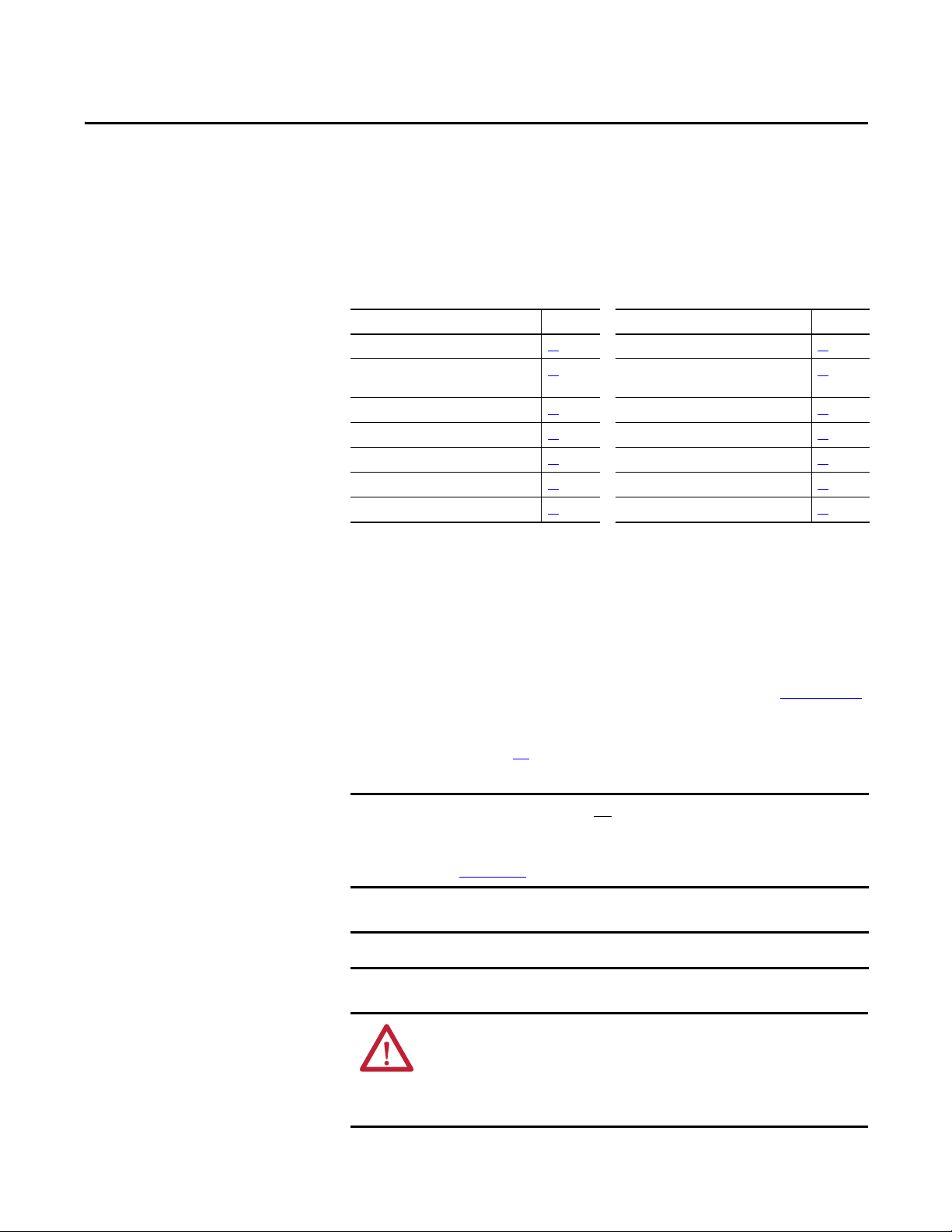
This table contains the changes made to this revision.
Top ic Pa ge
Added the Maximum Surrounding Air Temperature Specifications. 18
Updated the frame B drive dimensions to include a different depth dimension for certain catalog
numbers.
Updated the Typical Power Wiring Diagrams to illustrate connections for bother series A and series B
frame D fans.
Updated the Frame D, Series B Heatsink Cooling Fan Specifications to include information on fan air flow
verification after wiring.
Changed the name of parameter 467 from [Max Fld Curr Pct] to [Max Fld Flux Pct].
Note: The parameter name was only incorrect in this manual.
Added new values to the Testpoint Codes and Functions table. 229
Removed the Certifications and Specifications information. 232
20
45
71
Througho ut
manual
Changes to this manual for previous revisions are included in Appendix I History
of Changes on page 381
.
Rockwell Automation Publication 20P-UM001K-EN-P - July 2014 3
Page 4

Summary of Changes
4 Rockwell Automation Publication 20P-UM001K-EN-P - July 2014
Page 5

Table of Contents
Preface
Installation and Wiring
Drive Storage Conditions. . . . . . . . . . . . . . . . . . . . . . . . . . . . . . . . . . . . . . . . . 11
Drive Nameplate Data. . . . . . . . . . . . . . . . . . . . . . . . . . . . . . . . . . . . . . . . . . . . 12
Drive Series Letter. . . . . . . . . . . . . . . . . . . . . . . . . . . . . . . . . . . . . . . . . . . . 12
Drive Frame Sizes . . . . . . . . . . . . . . . . . . . . . . . . . . . . . . . . . . . . . . . . . . . . 12
Drive Firmware Version . . . . . . . . . . . . . . . . . . . . . . . . . . . . . . . . . . . . . . 12
Drive Specifications . . . . . . . . . . . . . . . . . . . . . . . . . . . . . . . . . . . . . . . . . . . . . . 12
Extra Resources . . . . . . . . . . . . . . . . . . . . . . . . . . . . . . . . . . . . . . . . . . . . . . . . . . 13
Technical Support . . . . . . . . . . . . . . . . . . . . . . . . . . . . . . . . . . . . . . . . . . . . . . . 13
Conventions. . . . . . . . . . . . . . . . . . . . . . . . . . . . . . . . . . . . . . . . . . . . . . . . . . . . . 13
General Precautions . . . . . . . . . . . . . . . . . . . . . . . . . . . . . . . . . . . . . . . . . . . . . . 14
Standard Drive Catalog Number Explanation . . . . . . . . . . . . . . . . . . . . . . 15
Standard Drive Catalog Number Explanation, Cont.. . . . . . . . . . . . . . . . 16
Standalone-Alone Regulator Catalog Numbers . . . . . . . . . . . . . . . . . . . . . 16
Chapter 1
Mount the Drive . . . . . . . . . . . . . . . . . . . . . . . . . . . . . . . . . . . . . . . . . . . . . . . . . 18
Operating Conditions and Temperatures. . . . . . . . . . . . . . . . . . . . . . . 18
Minimum Mounting Clearances. . . . . . . . . . . . . . . . . . . . . . . . . . . . . . . 18
Maximum Surrounding Air Temperature Specifications . . . . . . . . . 18
Approximate Drive Dimensions and Weights . . . . . . . . . . . . . . . . . . . . . . 19
Lifting PowerFlex DC Drives . . . . . . . . . . . . . . . . . . . . . . . . . . . . . . . . . . . . . 25
Mount Frame C and D Drives. . . . . . . . . . . . . . . . . . . . . . . . . . . . . . . . . 25
Remove the Drive Covers. . . . . . . . . . . . . . . . . . . . . . . . . . . . . . . . . . . . . . . . . 27
Frame A Drives . . . . . . . . . . . . . . . . . . . . . . . . . . . . . . . . . . . . . . . . . . . . . . 27
Frame B and C Drives . . . . . . . . . . . . . . . . . . . . . . . . . . . . . . . . . . . . . . . . 28
Frame D . . . . . . . . . . . . . . . . . . . . . . . . . . . . . . . . . . . . . . . . . . . . . . . . . . . . . 29
Isolation Transformers / Line Reactors . . . . . . . . . . . . . . . . . . . . . . . . . . . . 29
Contactors . . . . . . . . . . . . . . . . . . . . . . . . . . . . . . . . . . . . . . . . . . . . . . . . . . . . . . 30
AC Input Contactors. . . . . . . . . . . . . . . . . . . . . . . . . . . . . . . . . . . . . . . . . 31
DC Output Contactors. . . . . . . . . . . . . . . . . . . . . . . . . . . . . . . . . . . . . . . 31
Dynamic Brake Resistors. . . . . . . . . . . . . . . . . . . . . . . . . . . . . . . . . . . . . . 31
General Grounding Requirements. . . . . . . . . . . . . . . . . . . . . . . . . . . . . . . . . 32
Safety Ground (PE). . . . . . . . . . . . . . . . . . . . . . . . . . . . . . . . . . . . . . . . . . . 33
Power Feeder . . . . . . . . . . . . . . . . . . . . . . . . . . . . . . . . . . . . . . . . . . . . . . . . 33
Encoder/Resolver Ground Connections. . . . . . . . . . . . . . . . . . . . . . . . 33
Tachometer Ground Connections . . . . . . . . . . . . . . . . . . . . . . . . . . . . . 33
Grounding for Installations in an Ungrounded or High-Impedance,
Neutral Ground, or System . . . . . . . . . . . . . . . . . . . . . . . . . . . . . . . . . . . . . . . 34
Power Distribution . . . . . . . . . . . . . . . . . . . . . . . . . . . . . . . . . . . . . . . . . . . 34
CE Conformity . . . . . . . . . . . . . . . . . . . . . . . . . . . . . . . . . . . . . . . . . . . . . . . . . . 39
Low Voltage Directive . . . . . . . . . . . . . . . . . . . . . . . . . . . . . . . . . . . . . . . . 39
EMC Directive. . . . . . . . . . . . . . . . . . . . . . . . . . . . . . . . . . . . . . . . . . . . . . . 39
General Considerations . . . . . . . . . . . . . . . . . . . . . . . . . . . . . . . . . . . . . . . 39
Installation Requirements Related to the Low Voltage Directive. . 40
Rockwell Automation Publication 20P-UM001K-EN-P - July 2014 5
Page 6

Table of Contents
Installation Requirements Related to EN 61800-3 and the EMC
Directive. . . . . . . . . . . . . . . . . . . . . . . . . . . . . . . . . . . . . . . . . . . . . . . . . . . . . 40
Pollution Degree Ratings According to EN 61800-5-1 . . . . . . . . . . 41
Power Circuit Protection . . . . . . . . . . . . . . . . . . . . . . . . . . . . . . . . . . . . . . . . . 42
Control Power Circuit Protection . . . . . . . . . . . . . . . . . . . . . . . . . . . . . . . . . 42
Cable and Wiring Recommendations . . . . . . . . . . . . . . . . . . . . . . . . . . . . . . 43
Power Wiring . . . . . . . . . . . . . . . . . . . . . . . . . . . . . . . . . . . . . . . . . . . . . . . . . . . . 44
AC Input Voltages. . . . . . . . . . . . . . . . . . . . . . . . . . . . . . . . . . . . . . . . . . . . 44
DC Output Voltages. . . . . . . . . . . . . . . . . . . . . . . . . . . . . . . . . . . . . . . . . . 45
Typical Power Wiring Diagrams . . . . . . . . . . . . . . . . . . . . . . . . . . . . . . . 45
Armature Converter Connections . . . . . . . . . . . . . . . . . . . . . . . . . . . . . 50
Armature Voltage Feedback Connections. . . . . . . . . . . . . . . . . . . . . . . 53
Field Converter Connections . . . . . . . . . . . . . . . . . . . . . . . . . . . . . . . . . . 56
Field Current Configuration . . . . . . . . . . . . . . . . . . . . . . . . . . . . . . . . . . 60
Set DIP Switch S14 to the Correct Value . . . . . . . . . . . . . . . . . . . . . . . 60
Relay Outputs . . . . . . . . . . . . . . . . . . . . . . . . . . . . . . . . . . . . . . . . . . . . . . . . 62
Thermistors and Thermal Switches . . . . . . . . . . . . . . . . . . . . . . . . . . . . 62
Control Circuit Input Power . . . . . . . . . . . . . . . . . . . . . . . . . . . . . . . . . . 65
Frame C Heatsink Cooling Fan Specifications . . . . . . . . . . . . . . . . . . 69
Frame D, Series B Heatsink Cooling Fan Specifications . . . . . . . . . . 71
Frame C and D Armature Fuse Signal Terminals . . . . . . . . . . . . . . . . 73
DIP Switch and Jumper Settings. . . . . . . . . . . . . . . . . . . . . . . . . . . . . . . . . . . 75
I/O Wiring . . . . . . . . . . . . . . . . . . . . . . . . . . . . . . . . . . . . . . . . . . . . . . . . . . . . . . 80
I/O Signal and Control Wiring . . . . . . . . . . . . . . . . . . . . . . . . . . . . . . . . 81
I/O Wiring Examples . . . . . . . . . . . . . . . . . . . . . . . . . . . . . . . . . . . . . . . . 83
Digital Encoder Terminal Block . . . . . . . . . . . . . . . . . . . . . . . . . . . . . . . 86
DC Analog Tachometer Terminal Block . . . . . . . . . . . . . . . . . . . . . . . 88
Resolver Feedback Module . . . . . . . . . . . . . . . . . . . . . . . . . . . . . . . . . . . . 88
I/O and Control Wire Routing . . . . . . . . . . . . . . . . . . . . . . . . . . . . . . . . 89
Chapter 2
Drive Start Up
6 Rockwell Automation Publication 20P-UM001K-EN-P - July 2014
Drive Start Up Checklist. . . . . . . . . . . . . . . . . . . . . . . . . . . . . . . . . . . . . . . . . . 91
Before Applying Power to the Drive. . . . . . . . . . . . . . . . . . . . . . . . . . . . . . . . 92
Verify all Drive Configuration Settings . . . . . . . . . . . . . . . . . . . . . . . . . 92
Verify the Power Wiring . . . . . . . . . . . . . . . . . . . . . . . . . . . . . . . . . . . . . . 92
Verify the Control and I/O Wiring . . . . . . . . . . . . . . . . . . . . . . . . . . . . 92
Applying Power to the Drive . . . . . . . . . . . . . . . . . . . . . . . . . . . . . . . . . . . . . . 93
Apply Voltage to the Control Circuits. . . . . . . . . . . . . . . . . . . . . . . . . . 93
Verify the Control Voltages . . . . . . . . . . . . . . . . . . . . . . . . . . . . . . . . . . . 95
Load the Default Settings. . . . . . . . . . . . . . . . . . . . . . . . . . . . . . . . . . . . . . 95
Configure the Most Commonly Used Parameters . . . . . . . . . . . . . . . 95
Tune the Current Regulator . . . . . . . . . . . . . . . . . . . . . . . . . . . . . . . . . . 101
Verify Motor Rotation and Run Feedback Polarity Checks. . . . . . 103
Configure the Speed Feedback Parameters . . . . . . . . . . . . . . . . . . . . . 106
Tune the Speed Regulator . . . . . . . . . . . . . . . . . . . . . . . . . . . . . . . . . . . . 108
Verify Speed Reference Settings and Drive Operation. . . . . . . . . . . 110
Page 7

Chapter 3
Table of Contents
Programming and Parameters
Troubleshooting
About Parameters . . . . . . . . . . . . . . . . . . . . . . . . . . . . . . . . . . . . . . . . . . . . . . . 113
Parameters Table Example . . . . . . . . . . . . . . . . . . . . . . . . . . . . . . . . . . . 114
How Parameters are Organized. . . . . . . . . . . . . . . . . . . . . . . . . . . . . . . . . . . 115
File–Group–Parameter Order. . . . . . . . . . . . . . . . . . . . . . . . . . . . . . . . 115
Numbered List View. . . . . . . . . . . . . . . . . . . . . . . . . . . . . . . . . . . . . . . . . 115
Cross Reference Tables . . . . . . . . . . . . . . . . . . . . . . . . . . . . . . . . . . . . . . 115
Basic Parameter View . . . . . . . . . . . . . . . . . . . . . . . . . . . . . . . . . . . . . . . . 116
Advanced Parameter View . . . . . . . . . . . . . . . . . . . . . . . . . . . . . . . . . . . 118
Monitor File. . . . . . . . . . . . . . . . . . . . . . . . . . . . . . . . . . . . . . . . . . . . . . . . . . . . 123
Motor Control File. . . . . . . . . . . . . . . . . . . . . . . . . . . . . . . . . . . . . . . . . . . . . . 128
Speed Command File. . . . . . . . . . . . . . . . . . . . . . . . . . . . . . . . . . . . . . . . . . . . 145
Dynamic Control File . . . . . . . . . . . . . . . . . . . . . . . . . . . . . . . . . . . . . . . . . . . 151
Applications File . . . . . . . . . . . . . . . . . . . . . . . . . . . . . . . . . . . . . . . . . . . . . . . . 157
Utility File. . . . . . . . . . . . . . . . . . . . . . . . . . . . . . . . . . . . . . . . . . . . . . . . . . . . . . 173
Communications File . . . . . . . . . . . . . . . . . . . . . . . . . . . . . . . . . . . . . . . . . . . 187
Input / Output File . . . . . . . . . . . . . . . . . . . . . . . . . . . . . . . . . . . . . . . . . . . . . 191
Parameter Cross Reference – by Name . . . . . . . . . . . . . . . . . . . . . . . . . . . . 203
Parameter Cross Reference – by Number. . . . . . . . . . . . . . . . . . . . . . . . . . 209
Chapter 4
Faults and Alarms . . . . . . . . . . . . . . . . . . . . . . . . . . . . . . . . . . . . . . . . . . . . . . . 215
Drive Status . . . . . . . . . . . . . . . . . . . . . . . . . . . . . . . . . . . . . . . . . . . . . . . . . . . . 216
HIM Indicators . . . . . . . . . . . . . . . . . . . . . . . . . . . . . . . . . . . . . . . . . . . . . 217
Manually Clearing Faults . . . . . . . . . . . . . . . . . . . . . . . . . . . . . . . . . . . . . . . . 217
Fault Descriptions. . . . . . . . . . . . . . . . . . . . . . . . . . . . . . . . . . . . . . . . . . . . . . . 218
Clearing Alarms. . . . . . . . . . . . . . . . . . . . . . . . . . . . . . . . . . . . . . . . . . . . . . . . . 224
Alarm Descriptions . . . . . . . . . . . . . . . . . . . . . . . . . . . . . . . . . . . . . . . . . . . . . 224
Common Drive Symptoms and Corrective Actions . . . . . . . . . . . . . . . . 227
Drive will not start . . . . . . . . . . . . . . . . . . . . . . . . . . . . . . . . . . . . . . . . . . 227
Drive starts but motor does not turn and no armature current . . 228
The motor does not reach commanded speed . . . . . . . . . . . . . . . . . . 228
The motor is turning in the wrong direction . . . . . . . . . . . . . . . . . . 228
The motor reaches maximum speed immediately . . . . . . . . . . . . . . 229
Testpoint Codes and Functions . . . . . . . . . . . . . . . . . . . . . . . . . . . . . . . . . . 229
Supplemental Drive Information
Appendix A
Certifications and Specifications . . . . . . . . . . . . . . . . . . . . . . . . . . . . . . . . . 232
IP20 NEMA / UL Type Open Watts Loss . . . . . . . . . . . . . . . . . . . . . . . . 232
Communication Configurations . . . . . . . . . . . . . . . . . . . . . . . . . . . . . . . . . 234
Typical Programmable Controller Configurations . . . . . . . . . . . . . 234
Logic Command/Status Words . . . . . . . . . . . . . . . . . . . . . . . . . . . . . . 234
Drive Power Circuit Protection . . . . . . . . . . . . . . . . . . . . . . . . . . . . . . . . . . 236
Frame A and B Fuse Information . . . . . . . . . . . . . . . . . . . . . . . . . . . . . 236
Frame C and D Fuse Information. . . . . . . . . . . . . . . . . . . . . . . . . . . . . 242
Control Power Circuit Protection Fuses . . . . . . . . . . . . . . . . . . . . . . . . . . 249
Rockwell Automation Publication 20P-UM001K-EN-P - July 2014 7
Page 8

Table of Contents
Switching Power Supply Circuit Board Fuses . . . . . . . . . . . . . . . . . . 249
Frame B Pulse Transformer Circuit Board Fuses . . . . . . . . . . . . . . . 251
Frame C Transient Noise Filter Circuit Board Fuses. . . . . . . . . . . . 252
Frame D Overvoltage Clipping Circuit Board Fuses . . . . . . . . . . . . 253
AC Input Line Reactors and AC Input Contactors. . . . . . . . . . . . . . . . . 254
Isolation Transformers. . . . . . . . . . . . . . . . . . . . . . . . . . . . . . . . . . . . . . . . . . . 256
Dynamic Brake Resistor Kits and DC Output Contactors . . . . . . . . . . 258
DC Contactor Crimp Lug Kit Specifications . . . . . . . . . . . . . . . . . . . . . . 259
Alternate Dynamic Brake Resistor Kits and DC Output Contactors. 260
Alternate EMC Filters . . . . . . . . . . . . . . . . . . . . . . . . . . . . . . . . . . . . . . . . . . . 261
Terminal Adapter Kits for Frame D Drives . . . . . . . . . . . . . . . . . . . . . . . . 264
Appendix B
HIM Overview
Application Notes
External and Internal Connections . . . . . . . . . . . . . . . . . . . . . . . . . . . . . . . 265
LCD Display Elements . . . . . . . . . . . . . . . . . . . . . . . . . . . . . . . . . . . . . . . . . . 266
ALT Functions. . . . . . . . . . . . . . . . . . . . . . . . . . . . . . . . . . . . . . . . . . . . . . . . . . 266
Using the S.M.A.R.T. List Screen . . . . . . . . . . . . . . . . . . . . . . . . . . . . . 267
Menu Structure . . . . . . . . . . . . . . . . . . . . . . . . . . . . . . . . . . . . . . . . . . . . . . . . . 268
Viewing and Editing Parameters . . . . . . . . . . . . . . . . . . . . . . . . . . . . . . . . . . 270
LCD HIM . . . . . . . . . . . . . . . . . . . . . . . . . . . . . . . . . . . . . . . . . . . . . . . . . 270
Removing/Installing the HIM. . . . . . . . . . . . . . . . . . . . . . . . . . . . . . . . . . . . 271
Appendix C
Alpha Test Mode. . . . . . . . . . . . . . . . . . . . . . . . . . . . . . . . . . . . . . . . . . . . . . . . 273
Alpha Test Setup and Operation . . . . . . . . . . . . . . . . . . . . . . . . . . . . . 274
Analog Input Configuration . . . . . . . . . . . . . . . . . . . . . . . . . . . . . . . . . . . . . 276
Example 1: . . . . . . . . . . . . . . . . . . . . . . . . . . . . . . . . . . . . . . . . . . . . . . . . . . 276
Example 2: . . . . . . . . . . . . . . . . . . . . . . . . . . . . . . . . . . . . . . . . . . . . . . . . . . 276
Analog Input Signal Comparison . . . . . . . . . . . . . . . . . . . . . . . . . . . . . 277
Current / Speed Curve. . . . . . . . . . . . . . . . . . . . . . . . . . . . . . . . . . . . . . . . . . . 278
Drive Reference and Feedback Scaling. . . . . . . . . . . . . . . . . . . . . . . . . . . . . 279
Armature Voltage Feedback . . . . . . . . . . . . . . . . . . . . . . . . . . . . . . . . . . 280
DC Analog Tachometer Feedback . . . . . . . . . . . . . . . . . . . . . . . . . . . . 280
Encoder Feedback . . . . . . . . . . . . . . . . . . . . . . . . . . . . . . . . . . . . . . . . . . . 280
Drive Reference and Feedback Scaling Examples . . . . . . . . . . . . . . . 280
Speed Feedback. . . . . . . . . . . . . . . . . . . . . . . . . . . . . . . . . . . . . . . . . . . . . . 283
Droop Compensation . . . . . . . . . . . . . . . . . . . . . . . . . . . . . . . . . . . . . . . . . . . 285
Field Weakening Mode Configuration (v1.006) . . . . . . . . . . . . . . . . . . . 285
Using a DC Contactor Only (Firmware v1.006 Only) . . . . . . . . . . 286
Using a DC Contactor and a Dynamic Brake (Firmware
v1.006 Only) . . . . . . . . . . . . . . . . . . . . . . . . . . . . . . . . . . . . . . . . . . . . . . . . 286
Using an Inverting Fault Device Only (Firmware v1.006 Only). . 286
Using a DC Contactor and an Inverting Fault Device (Firmware
v1.006 Only) . . . . . . . . . . . . . . . . . . . . . . . . . . . . . . . . . . . . . . . . . . . . . . . . 287
Using a DC Contactor, a Dynamic Brake and an Inverting Fault
Device (Firmware v1.006 Only). . . . . . . . . . . . . . . . . . . . . . . . . . . . . . . 288
8 Rockwell Automation Publication 20P-UM001K-EN-P - July 2014
Page 9

Table of Contents
Lifting/Torque Proving . . . . . . . . . . . . . . . . . . . . . . . . . . . . . . . . . . . . . . . . . 289
Tuning The Motor For Torque Prove Applications . . . . . . . . . . . . 291
Crane Setup with Encoder/Resolver Feedback . . . . . . . . . . . . . . . . . 291
Crane Setup - Encoderless. . . . . . . . . . . . . . . . . . . . . . . . . . . . . . . . . . . . 296
Manually Tuning the Speed Regulator for Firmware Version 6.xxx . . 301
PID Function. . . . . . . . . . . . . . . . . . . . . . . . . . . . . . . . . . . . . . . . . . . . . . . . . . . 302
Configure a Line Speed Signal . . . . . . . . . . . . . . . . . . . . . . . . . . . . . . . . 303
Configure the Feedback Signal in the Follower Drive(s) . . . . . . . . 304
Configure the Tension Set Point Signal in the Follower Drive(s) 306
Reference Control . . . . . . . . . . . . . . . . . . . . . . . . . . . . . . . . . . . . . . . . . . . . . . 307
“Auto” Speed Sources. . . . . . . . . . . . . . . . . . . . . . . . . . . . . . . . . . . . . . . . 307
“Manual” Speed Sources . . . . . . . . . . . . . . . . . . . . . . . . . . . . . . . . . . . . . 307
Changing Speed Sources . . . . . . . . . . . . . . . . . . . . . . . . . . . . . . . . . . . . . 307
Torque Reference Source . . . . . . . . . . . . . . . . . . . . . . . . . . . . . . . . . . . . 307
Auto/Manual Examples. . . . . . . . . . . . . . . . . . . . . . . . . . . . . . . . . . . . . . 308
Resolver Cable Balance Tuning Test . . . . . . . . . . . . . . . . . . . . . . . . . . . . . . 309
Performing the Cable Balance Tuning Test . . . . . . . . . . . . . . . . . . . . 309
Resolver Type Selection . . . . . . . . . . . . . . . . . . . . . . . . . . . . . . . . . . . . . . . . . 310
Scale Blocks. . . . . . . . . . . . . . . . . . . . . . . . . . . . . . . . . . . . . . . . . . . . . . . . . . . . . 311
Linking Parameters Via the Scale Block Parameters. . . . . . . . . . . . . 312
SCR Diagnostic Tests . . . . . . . . . . . . . . . . . . . . . . . . . . . . . . . . . . . . . . . . . . . 312
Open SCR Test . . . . . . . . . . . . . . . . . . . . . . . . . . . . . . . . . . . . . . . . . . . . . 313
Shorted SCR Test . . . . . . . . . . . . . . . . . . . . . . . . . . . . . . . . . . . . . . . . . . . 314
S-curve Configuration . . . . . . . . . . . . . . . . . . . . . . . . . . . . . . . . . . . . . . . . . . . 315
S-curve Acceleration Ramp Example: . . . . . . . . . . . . . . . . . . . . . . . . . 316
Speed Regulation Functions. . . . . . . . . . . . . . . . . . . . . . . . . . . . . . . . . . . . . . 317
Adaptive Speed Regulator . . . . . . . . . . . . . . . . . . . . . . . . . . . . . . . . . . . . 317
Speed Up Function . . . . . . . . . . . . . . . . . . . . . . . . . . . . . . . . . . . . . . . . . . 320
Speed Threshold Indicators . . . . . . . . . . . . . . . . . . . . . . . . . . . . . . . . . . 321
Speed Zero Function . . . . . . . . . . . . . . . . . . . . . . . . . . . . . . . . . . . . . . . . 322
Speed Draw Function. . . . . . . . . . . . . . . . . . . . . . . . . . . . . . . . . . . . . . . . 323
Speed / Torque Mode Selection . . . . . . . . . . . . . . . . . . . . . . . . . . . . . . . . . . 324
Zero Torque Mode . . . . . . . . . . . . . . . . . . . . . . . . . . . . . . . . . . . . . . . . . . 324
Speed Regulation Mode. . . . . . . . . . . . . . . . . . . . . . . . . . . . . . . . . . . . . . 325
Torque Regulation Mode . . . . . . . . . . . . . . . . . . . . . . . . . . . . . . . . . . . . 325
eed Limited Adjustable Torque (SLAT) Min Mode and SLAT Max
Sp
Mode. . . . . . . . . . . . . . . . . . . . . . . . . . . . . . . . . . . . . . . . . . . . . . . . . . . . . . . 325
Sum Mode . . . . . . . . . . . . . . . . . . . . . . . . . . . . . . . . . . . . . . . . . . . . . . . . . . 329
Start At Powerup . . . . . . . . . . . . . . . . . . . . . . . . . . . . . . . . . . . . . . . . . . . . . . . 330
Fine Tuning the Regulators . . . . . . . . . . . . . . . . . . . . . . . . . . . . . . . . . . . . . . 331
Manually Adjusting the Current Regulator Tune Settings . . . . . . 332
Fine Tuning the Field Current Regulator. . . . . . . . . . . . . . . . . . . . . . 334
Fine Tuning the Speed Regulator . . . . . . . . . . . . . . . . . . . . . . . . . . . . . 337
Fine Tuning the Voltage Regulator in the Field Converter . . . . . . 339
Tuning the Field Current Curve. . . . . . . . . . . . . . . . . . . . . . . . . . . . . . 341
Rockwell Automation Publication 20P-UM001K-EN-P - July 2014 9
Page 10

Table of Contents
Appendix D
Control Block Diagrams
Installing a Communication Adapter
Optional Analog and Digital I/O
Expansion Circuit Board
Optional 115V AC to 24V DC I/O
Converter Circuit Board
Diagram Conventions . . . . . . . . . . . . . . . . . . . . . . . . . . . . . . . . . . . . . . . 343
Appendix E
Communication Adapter Kits. . . . . . . . . . . . . . . . . . . . . . . . . . . . . . . . . . . . 367
What The Communication Adapter Kit Includes . . . . . . . . . . . . . . . . . . 367
Tools That You Need. . . . . . . . . . . . . . . . . . . . . . . . . . . . . . . . . . . . . . . . . . . . 367
Safety Precautions . . . . . . . . . . . . . . . . . . . . . . . . . . . . . . . . . . . . . . . . . . . . . . . 368
Installing the Communication Adapter Module in the Drive. . . . . . . . 368
Frame A . . . . . . . . . . . . . . . . . . . . . . . . . . . . . . . . . . . . . . . . . . . . . . . . . . . . 369
Frames B and C . . . . . . . . . . . . . . . . . . . . . . . . . . . . . . . . . . . . . . . . . . . . . 370
Frame D . . . . . . . . . . . . . . . . . . . . . . . . . . . . . . . . . . . . . . . . . . . . . . . . . . . . 371
Appendix F
What This Option Board Provides. . . . . . . . . . . . . . . . . . . . . . . . . . . . . . . . 373
I/O Expansion Board Wiring. . . . . . . . . . . . . . . . . . . . . . . . . . . . . . . . . . . . . 373
Appendix G
What This Option Board Provides. . . . . . . . . . . . . . . . . . . . . . . . . . . . . . . . 375
I/O Converter Board Wiring. . . . . . . . . . . . . . . . . . . . . . . . . . . . . . . . . . . . . 376
PowerFlex DC Standalone Regulator
Installation
History of Changes
Index
Appendix H
Installation and Wiring Instructions . . . . . . . . . . . . . . . . . . . . . . . . . . . . . . 379
Appendix I
20P-UM001J-EN-P, February 2014 . . . . . . . . . . . . . . . . . . . . . . . . . . . . . . 381
20P-UM001I-EN-P, February 2013 . . . . . . . . . . . . . . . . . . . . . . . . . . . . . . 382
20P-UM001H-EN-P, April 2011. . . . . . . . . . . . . . . . . . . . . . . . . . . . . . . . . 383
20P-UM001G-EN-P, October 2010 . . . . . . . . . . . . . . . . . . . . . . . . . . . . . . 384
20P-UM001F-EN-P, June 2009 . . . . . . . . . . . . . . . . . . . . . . . . . . . . . . . . . . 385
10 Rockwell Automation Publication 20P-UM001K-EN-P - July 2014
Page 11

Preface
Top ic Pa ge
Drive Storage Conditions 11
Drive Nameplate Data 12
Drive Specifications 12
Extra Resources 13
Technical Support 13
Convent ions 13
General Precautions 14
Standard Drive Catalog Number Explanation 15
Standalone-Alone Regulator Catalog Numbers 16
The purpose of this manual is to provide you with the basic information required
to install, start-up, and troubleshoot the PowerFlex DC drive. This manual is
intended for qualified personnel. You must be able to program and operate DC
drives. In addition, you must have an understanding of the parameter settings and
functions that are detailed in this manual.
Drive Storage Conditions
If it is necessary to store the drive for any length of time before installation, follow
these storage guidelines to provide satisfactory start-up operation and retain
warranty coverage:
• After receipt and inspection, repack the drive in its original shipping
container and store in a clean, dry place.
• Place where the ambient temperatures do not exceed -25°C (-13°F) or
55°C (131°F)
• Place where the range of relative air humidity does not exceed 5…95%.
• At an altitude of less than 3,000 meters (10,000 ft.) above sea level.
Rockwell Automation Publication 20P-UM001K-EN-P - July 2014 11
Page 12
Preface
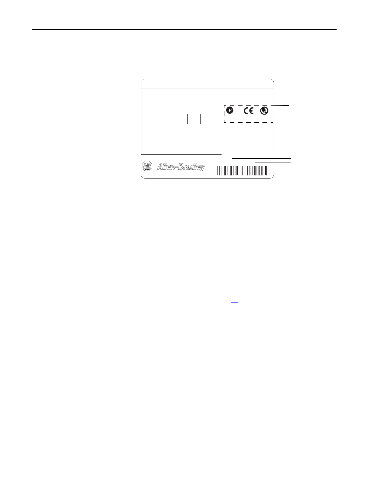
Note: Certification
Marks Location.
See the data
nameplate label on
your drive for actual
agency certifications.
Drive frame size
Drive serial number
Drive series letter
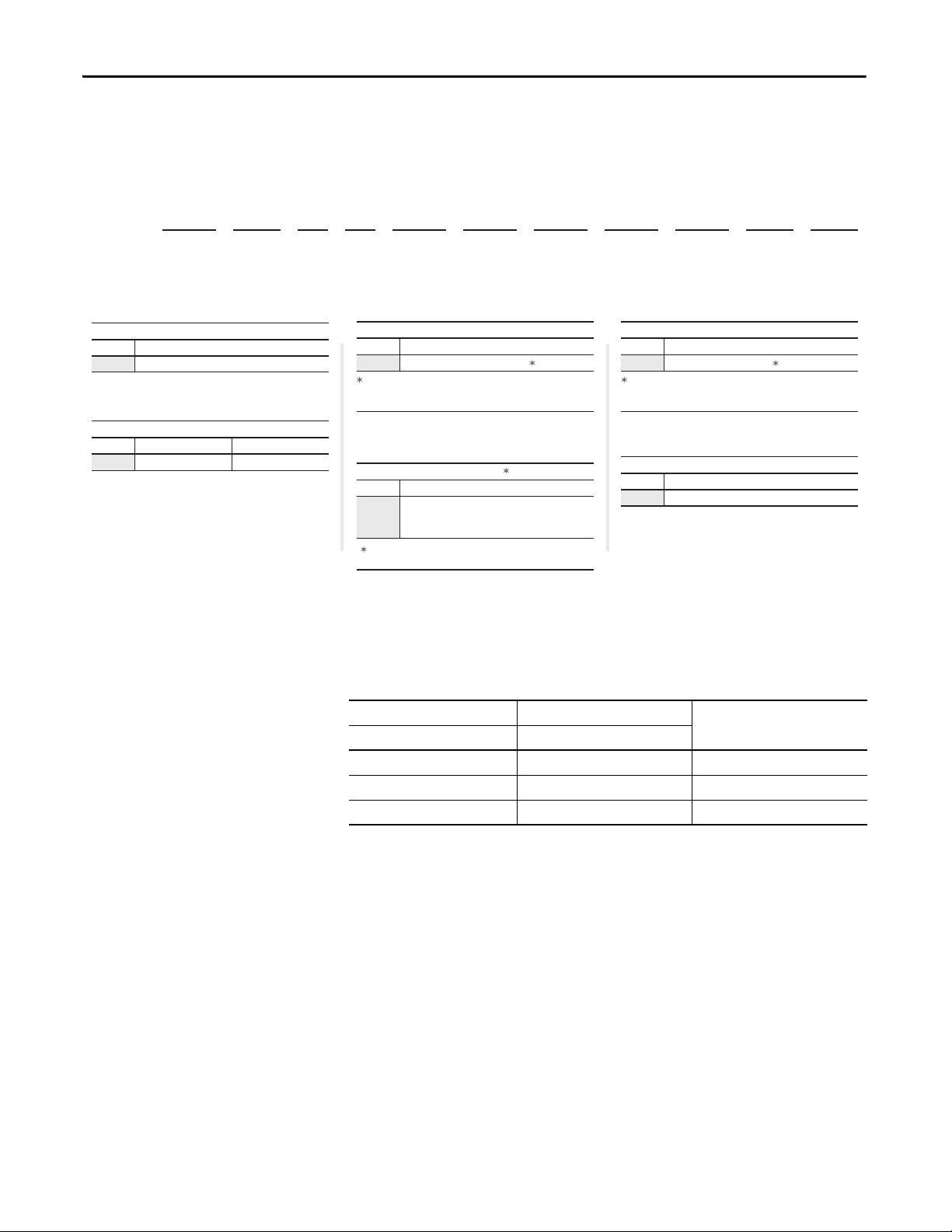
Drive Nameplate Data
The PowerFlex DC drive contains a data nameplate label on the side of each
drive. This nameplate identifies the specific model number, applicable AC input
power, and DC output power data. Include this information when
communicating with Rockwell Automation personnel about this product.
Cat No.
20P41AD4P1RA0NNN
UL Type OPEN/IP20
Input: 460VAC 50/60 Hz 3.3A 3 Phase
Output: 500VDC 4.1A REGEN 2.0HP
1 Min Overload Amps
3 Sec Overload Amps
DC Field:
Input: 460VAC 50/60 Hz 10A max. 1 Phase
Output: 360VDC 10A max.
Regulator Power: 115/230VAC 50/60 Hz 1.0/0.5A 1 Phase
MFD. in 2XXX on MMM DD
Made in Italy
6.2
8.2
EXAMPLE ONLY
Series: A
I/O: 24VDC (Standard)
Original Firmware V. 1.001
N223
Frame: A
Serial Number: A23E0042
C
Ind. Cont.
Eq. 31KF
Listed
R
US
Drive Series Letter
Drive Specifications
Series B drives are identified as such on the data nameplate label. The drive series
letter is on the top, right side of the label.
Drive Frame Sizes
Similar PowerFlex DC drive ratings are grouped into frame sizes to make
ordering spare parts and drive dimensions simpler. The drive frame size is listed
just above the serial number on the data nameplate label. See the Standard Drive
Catalog Number Explanation on page 15
for a list of drive catalog numbers and
their respective frame sizes.
Drive Firmware Version
The original firmware version of the drive as shipped from the factory appears on
the data nameplate label just above the certifications. If the firmware version has
been upgraded since the drive was shipped, you can view the current version on
the HIM (if installed). See Diagnostics Menu on page 269
For drive specification information, see the PowerFlex Digital DC Drive,
Technical Data, 20P-TD001
.
for details.
12 Rockwell Automation Publication 20P-UM001K-EN-P - July 2014
Page 13

Preface
Extra Resources
These documents contain more information on related products from Rockwell
Automation.
Resource Description
Preventive Maintenance of Industrial Control and Drive
System Equipment, DRIVES-TD001
Safety Guidelines for the Application, Installation, and
Maintenance of Solid State Control, SGI-1.1
A Global Reference Guide for Reading Schematic Diagrams,
100-2.10
Guarding Against Electrostatic Damage, 8000-4.5.2 Provides common practices that can help guard against
Industrial Automation Wiring and Grounding Guidelines,
publication 1770-4.1
Product Certifications website, http://ab.com
Provides a checklist for performing preventive
maintenance.
Provides general guidelines for the application,
installation, and maintenance of solid-state control in the
form of individual devices or packaged assemblies that
incorporate solid-state components.
Provides a simple cross-reference of common schematic/
wiring diagram symbols that are used throughout various
parts of the world.
ESD.
Provides general guidelines for installing a Rockwell
Automation industrial system.
Provides declarations of conformity, certificates, and other
certification details.
You can view or download publications at
http://www.rockwellautomation.com/literature
. To order paper copies of
technical documentation, contact your local Allen-Bradley distributor or
Rockwell Automation sales representative.
Technical Support
Conventions
For Allen-Bradley Drives Technical Support:
Title Online at. . .
Allen-Bradley Drives Technical Support www.ab.com/support/abdrives
• To help differentiate parameter names and LCD display text from other
text, the following conventions are used:
– Parameter names appear in [brackets].
For example: [Armature Voltage].
– Display text appears in “quotes.” For example: “Enabled.”
• The following words are used throughout the manual to describe an
action:
Word Mean ing
Can Possible, able to do something
Cannot Not possible, not able to do something
May Permitted, allowed
Must Unavoidable, you must do this
Rockwell Automation Publication 20P-UM001K-EN-P - July 2014 13
Page 14
Preface
General Precautions
AT TE NT IO N: This drive contains ESD (Electrostatic Discharge) sensitive parts and
assemblies. Static control precautions are required when you install, test, service,
or repair this assembly. If ESD control procedures are not followed, component
damage can result. If you are not familiar with static control procedures, see
publication 8000-4.5.2, “Guarding Against Electrostatic Damage” or any other
applicable ESD protection handbook.
AT TE NT IO N: An incorrectly applied or installed drive can result in component
damage or a reduction in product life. Installation or application errors, such as,
an undersized motor, incorrect or inadequate AC supply, or excessive surrounding
air temperatures can result in malfunction of the system.
AT TE NT IO N: Allow only qualified personnel, familiar with DC drives and
associated machinery, to plan or implement the installation, start-up and
subsequent maintenance of the system. Failure to comply can result in personal
injury and equipment damage.
AT TE NT IO N: An incorrectly applied or installed bypass system can result in
component damage or reduction in product life. The most common causes are:
• An AC line connection to the drive output or control terminals.
• Improper bypass or output circuits that are not Allen-Bradley approved.
• Output circuits that do not connect directly to the motor.
Contact Allen-Bradley for assistance with your application or installation.
14 Rockwell Automation Publication 20P-UM001K-EN-P - July 2014
Page 15
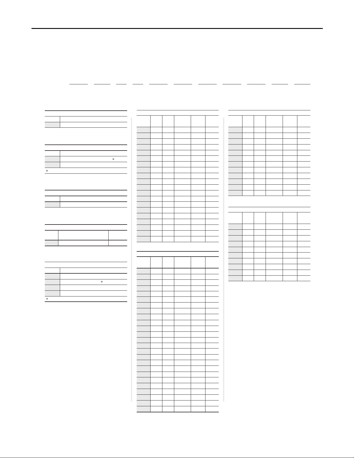
Standard Drive Catalog
Position
1-3 4 5 6 7 8-10 11 12 13 14 15 16
20P 4 1 A D 4P1 R A 0 N N N
abcdef gh i jkl
a
Drive
Code Type
20P PowerFlex DC
b
Motor Operation
Code Type
2 Two Quadrant Operation
4 Four Quadrant Operation
c
Input Type
Code Type
1 6 Pulse
d
Enclosure
Code Enclosure Rating
Conform.
Coat
A IP20, NEMA/UL Type Open
e
Input Voltage
Code Voltage
B 230V AC
D 460V AC
E 600V AC
F 690V AC
f1
f2
Yes
Not available for 230V AC input drives.
Use this code for 400V AC input applications.
f3
f4
2
3
5
7.5
10
15
20
25
30
40
50
60
75
100
125
150
200
250
300
400
500
600
700
800
900
1.5
2.2
3.7
5.5
7.5
11
15
18.5
22
30
37
45
56
75
93
112
149
187
224
298
373
447
552
597
671
4.1
6
10
14
19
27
35
45
52
73
86
100
129
167
207
250
330
412
495
667
830
996
1162
1238
1494
A
A
A
A
A
A
A
A
A
A
A
A
A
B
B
B
B
B
C
C
D
D
D
D
D
10
10
10
10
10
10
10
10
10
14
14
14
14
20
20
20
20
20
20
20
40
40
70
70
70
Hp
Armature
Amps
Frame
Field
Amps
Code kW
460V, 60 Hz Input
4P1
6P0
010
014
019
027
035
045
052
073
086
100
129
167
207
250
330
412
495
667
830
996
1K1
1K3
1K4
1.5
2
3
5
7.5
10
15
20
25
30
40
50
60
75
100
125
150
200
250
300
1.2
1.5
2.2
3.7
5.5
7.5
11
15
18.5
22
30
37
45
56
75
93
112
149
186
224
7
9
12
20
29
38
55
73
93
110
146
180
218
265
360
434
521
700
875
1050
A
A
A
A
A
A
A
A
A
A
B
B
B
B
B
B
C
C
D
D
10
10
10
10
10
10
10
14
14
14
20
20
20
20
20
20
20
20
40
40
Hp
Armature
Amps
Frame
Field
Amps
Code kW
230V, 60 Hz Input
7P0
9P0
012
020
029
038
055
073
093
110
146
180
218
265
360
434
521
700
875
1K0
50
75
100
200
300
400
500
600
800
900
1000
1250
37
56
75
149
224
298
373
447
597
671
746
932
67.5
101.3
135
270
405
540
675
810
1080
1215
1350
1668
B
B
B
B
B
C
C
D
D
D
D
D
20
20
20
20
20
20
20
40
40
40
40
40
Hp
Armature
Amps
Frame
Field
Amps
Code kW
575V, 60 Hz Input
067
101
135
270
405
540
675
810
1K0
1K2
1K3
1K6
298
373
447
552
597
671
746
820
932
1044
Hp
Armature
Amps
Frame
Field
Amps
Code kW
690V, 60 Hz Input
452
565
678
791
904
1K0
1K1
1K2
1K4
1K5
400
500
600
700
800
900
1000
1100
1250
1400
452
565
678
791
904
1017
1130
1243
1413
1582
C
C
D
D
D
D
D
D
D
D
20
20
40
40
40
40
70
70
70
70
Number Explanation
Preface
Rockwell Automation Publication 20P-UM001K-EN-P - July 2014 15
Page 16
Preface
Position
1-3 4 5 6 7 8-10 11 12 13 14 15 16
20P 4 1 A D 4P1 R A 0 N N N
abcdefghi jkl
g
Field Supply
Code Type
R Single-Phase Regulated
h
Packaging/Documentation
Code Shipping Carton User Manual
A Yes Yes
i
HIM
Code Operator Interface
0 Blank Cover
Standard - for user installed options, see
Human Interface and Wireless Interface
Modules on page 9.
j
I/O Options
Code Control
N
None (8 - 24V DC Digital Inputs,
4 Digital Outputs, 3 Analog Inputs,
and 2 Analog Outputs are Standard)
k
Communication Options
Code Description
N None
l
Cabinet Options
Code Type
N None
Standard - for user installed options, see
Communication Option Kits on page 10.
All I/O Options are purchased separately and
are user installed. See I/O Options on page 9.
Standard Drive Catalog Number Explanation, Cont.
Standalone-Alone Regulator Catalog Numbers
Conformally coated circuit boards are provided with the following catalog
numbers.
230V / 460V AC Input Regulators 575V / 690V AC Input Regulators Field Amps
Cat. No. Cat. No.
23PMD4 23PMF4 40
23PMD7 23PMF7 70
(1)
23PAMP
(1) Gate Amplifier - used with all voltage classes of the Stand-Alone Regulator. Note: The Stand-Alone Re gulator and Gate Amplifier are
currently sold through Rockwell Automation Drive Systems only. Consult the factory for availability.
23PAMP
(1)
(1)
16 Rockwell Automation Publication 20P-UM001K-EN-P - July 2014
Page 17
Chapter 1
IMPORTANT
IMPORTANT
Installation and Wiring
Topic Page Topic Page
Mount the Drive 18 CE Conformity 39
Approximate Drive Dimensions and
Wei ght s
Lifting PowerFlex DC Drives 25 Co ntrol Power Circ uit Protection 42
Remove the Drive Covers 27 Cable and Wiring Recommendations 43
Isolation Transformers / Line Reactors 29 Power Wiring 44
Contac tors 30 DIP Switch and Jumper Settings 75
General Grounding Requirements 32 I/O Wiring 80
19 Power Circuit Protection 42
This chapter provides information on how to mount and wire the PowerFlex DC
drive.
Most start-up difficulties are the result of incorrect wire connections. Take all
precautions to assure that wire connections are done as instructed. All items must
be read and understood before the actual installation begins.
For PowerFlex DC Stand-Alone Regulator (SAR) installations, see Appendix H
for important installation and configuration information. A 23PMDx catalog
number on the data nameplate on the drive identifies a SAR. (see Drive
Nameplate Data on page 12
for location).
The PowerFlex DC drive is not designed for use with multiple motor
applications or resistive loads. Contact your Local Solution Center for multiple
motor applications. See Local Solution Centers, publication
DSDC-BR001
, for more information.
The recommended drive to motor horsepower ratio is 2:1.
AT TE NT IO N: The following information is merely a guide for proper installation.
Rockwell Automation cannot assume responsibility for the compliance or the
noncompliance to any code, national, local or otherwise for the proper
installation of this drive or associated equipment. If codes are ignored during
installation, a hazard of personal injury and equipment damage exists.
Rockwell Automation Publication 20P-UM001K-EN-P - July 2014 17
Page 18
Chapter 1 Installation and Wiring
10 mm
10 mm
50 mm
(0.4 in.)
(0.4 in.) (2.0 in.)
10 mm
(0.4 in.)
150 mm (6.0 in.)
150 mm (6.0 in.)
150 mm (6.0 in.)
STS
PORT
MOD
NET A
NET B
STS
PORT
MOD
NET A
NET B
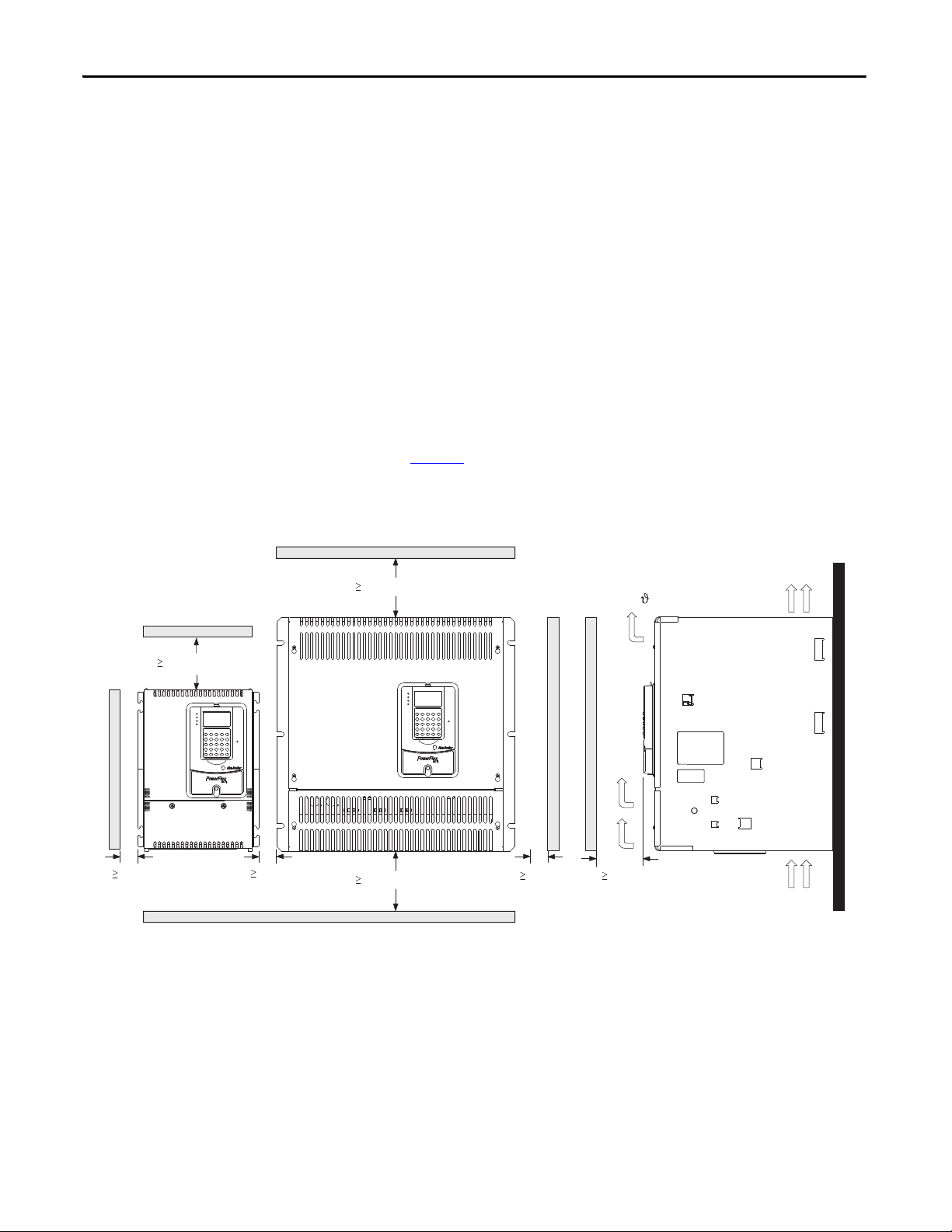
Airflow through the drive
must not be impeded.
Mount the Drive
Operating Conditions and Temperatures
PowerFlex DC drives are designed to operate at 0…50 °C (32…122 °F)
surrounding air temperature without derating. The drive must be mounted in a
clean, dry location. Contaminants such as oils, corrosive vapors, and abrasive
debris must be kept out of the enclosure. NEMA / UL Type Open, IP20
enclosures are intended for indoor use primarily to provide a degree of protection
against contact with enclosed equipment. These enclosures offer no protection
against airborne contaminants.
Minimum Mounting Clearances
Minimum clearance requirements are intended to be from drive to drive. Other
objects can occupy this space; however, reduced airflow can cause protection
circuits to fault the drive. The drive must be mounted in a vertical orientation as
shown in Figure 1
vertical. Intake air temperature must not exceed the product specification.
Figure 1 - Drive Enclosure Minimum Mounting Clearances
and must not be mounted at an angle greater than 30° from
Maximum Surrounding Air Temperature Specifications
• 0…50 °C (32…122 °F), typical
• De-rate 1.25% for every 1 °C (°F) over 50 °C (122 °F), to 55 °C (131 °F)
• Additional cooling is required for temperatures above 55 °C (131 °F)
18 Rockwell Automation Publication 20P-UM001K-EN-P - July 2014
Page 19
Installation and Wiring Chapter 1
A
B
A2
B1
C
STS
PORT
MOD
NET A
NET B
A1
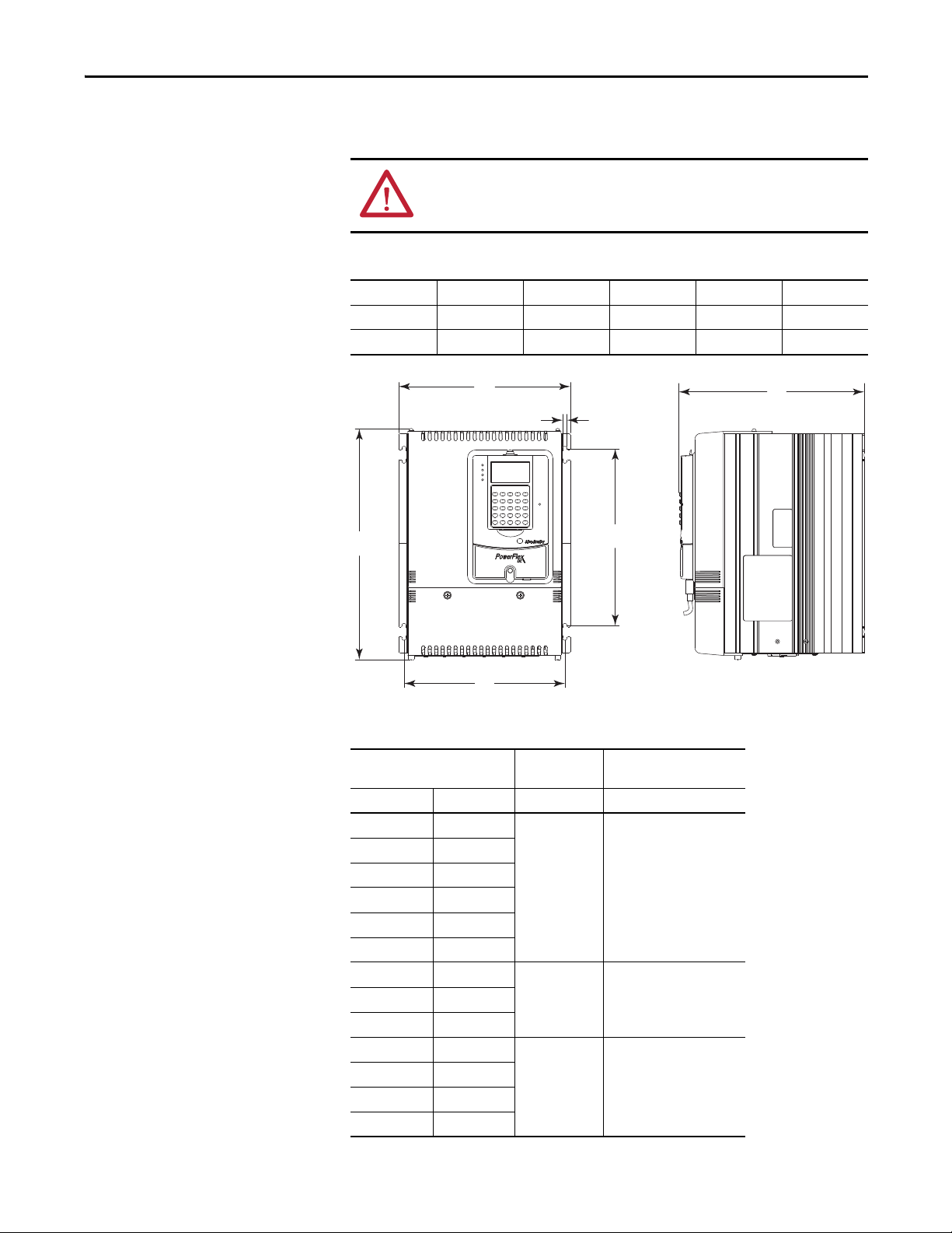
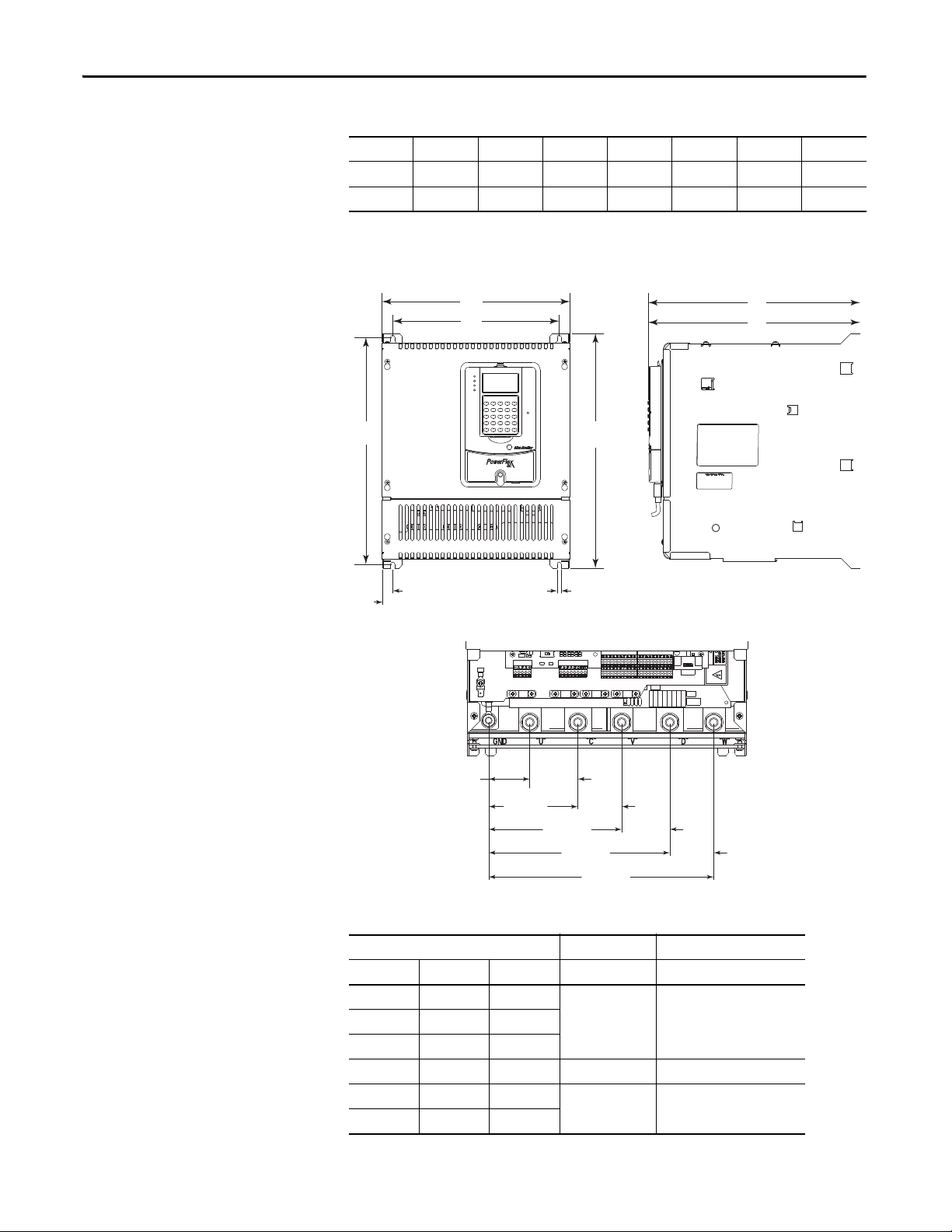
Approximate Drive Dimensions and Weights
The PowerFlex DC drive is available in a NEMA / UL Type Open, IP20
enclosure only. Follow all mounting clearances to provide proper drive operation.
ATTENTION: Remove all loose packing materials, including the containers of
desiccants (if any), from the drive enclosure before you mount and energize the
drive.
Figure 2 - Frame A Drive Dimensions
A B C A1A2B1
mm (in.) mm (in.) mm (in.) mm (in.) mm (in.) mm (in.)
267 (10.5) 359 (14.0) 287 (11.3) 7 (0.3) 250 (9.8) 275 (10.8)
Table 1 - Frame A Weights
Drive Current Rating Code Drive Weight Drive and Packaging
230V 460V kg (lb) kg (lb)‘
7P0 4P1
9P0 6P0
012 010
020 014
–019
029 027
8.4 (18.5) 10.5 (23.2)
038 035
–052
073 073
093 086
8.8 (19.4) 11 (24.3)055 045
10.8 (23.8) 13 (28.7)
110 100
–129
Weig ht
Rockwell Automation Publication 20P-UM001K-EN-P - July 2014 19
Page 20
Chapter 1 Installation and Wiring
A
A1
B1
C1
B
A2
STS
PORT
MOD
NET A
NET B
A3
45.2 (1.8)
98.5 (3.9)
53.1 (2.1)
48.5 (1.9)
147.0 (5.8) 53.1 (2.1)
48.5 (1.9)
200.1 (7.9)
248.6 (9.8)
C2
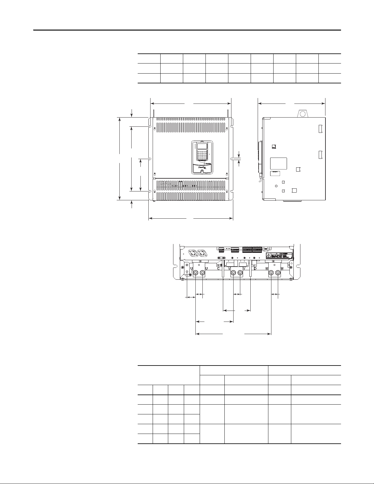
Terminal Details Dimensions in mm (in.)
Figure 3 - Frame B Drive Dimensions
A A1A2A3B B1C1C2
mm (in.) mm (in.) mm (in.) mm (in.) mm (in.) mm (in.) mm (in.) mm (in.)
311 (12.2) 275 (10.8) 16.5 (0.65) 7 (0.3) 388 (15.3) 375 (14.8) 350 (13.8) 380 (15.0)
(1) Only frame B drive catalog numbers 20P21AD330, 20P21AD412, 20P21AE405, 20P41AB36 0, 20P41AB434, 20P41AD330,
20P41AD412, 20P41AE405.
(1)
Table 2 - Frame B Weights
Drive w/ND Rating Code Drive Weight Drive and Packaging Weight
230V 460V 575V kg (lb) kg (lb)
146 167 067
25.5 (56.2) 27.5 (60.6)180 207 101
218 – 135
265 250 270 29.5 (65.0) 31.5 (69.5)
360 330 405
434 412 –
32 (70.5) 34 (75)
20 Rockwell Automation Publication 20P-UM001K-EN-P - July 2014
Page 21
Installation and Wiring Chapter 1
B1
B2
B3
A
A1 C
B
B4
STS
PORT
MOD
NET A
NET B
B5
310.0 (12.2)
155.0 (6.1)
113.0
(4.5)
28.0
(1.1)
28.0
(1.1)
28.0
(1.1)
35.5 (1.4)
Terminal Details Dimensions in mm (in.)
Figure 4 - Frame C Drive Dimensions
A A1 B B1 B2 B3 B4 B5 C
mm (in.) mm (in.) mm (in.) mm (in.) mm (in.) mm (in.) mm (in.) mm (in.) mm (in.)
521 (20.5) 499 (19.7) 511 (20.1) 400 (15.7) 200 (7.9) 55 (2.2) 56 (2.2) 10.5 (0.4) 416 (16.4)
Table 3 - Frame C Weights
Drive w/ND Rating Code Weight - Regenerative Drives Weight - Non-regenerative Drives
230V 460V 575V 690V kg (lb) kg (lb) kg (lb) kg (lb)
– 495 – 61 (134.5) 83 (183.0) 57 (125.7) 79 (174.2)
521 667 –
700 – –
– – 540 452
– – 675 565
Drive Drive and Packaging Drive Drive and Packaging
65 (143.3) 87 (191.8) 62 (136.7) 84 (185.2)
72 (158.7) 94 (207.2) 68 (150.0) 90 (198.4)
Rockwell Automation Publication 20P-UM001K-EN-P - July 2014 21
Page 22
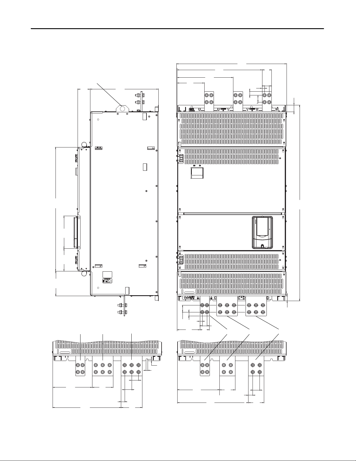
Chapter 1 Installation and Wiring
Dimensions of terminals U, V, and W are the same.
Dimensions are shown in mm and (in.)
Lifting flange
Note: 134 mm (5.3 in.) C and D terminals are installed on 460V AC input, 800 and 900 Hp, 575V AC input, 1000 Hp, and 690V AC input,
1100, 1200, 1250, and 1400 Hp drives only. All other frame D ratings have 100 mm (4.0 in.) C and D terminals.
PE C D
PE C D
80.5
(3.2)
Figure 5 - Frame D Dimensions - Right Side and Front Views
544
(21.4)
359
(14.1)
436.5
(17.2)
174
(6.9)
704
(27.7)
25
(1.0)
15
(0.6)
44.5
(1.8)
60
(2.4)
30
(1.2)
42
(1.7)
792
(31.2)
208
(8.2)
144
(5.7)
157.5
(6.2)
252.5
(10.0)
437.5
(17.2)
134
(5.3)
22.6
(0.9)
44.5
(1.8)
134
(5.3)
44.5
(1.8)
10.5
(0.4)
10
(0.4)
44.5
25
(1.8)
15
(1.0)
(0.6)
146
(5.7)60(2.4)
(1.2)
269.5
(10.6)
454.5
(18.0)
1250
(49.2)
32
(1.3)
30
44.5
27.8
(1.1)
(1.8)
100
(4.0)
100
(4.0)
22 Rockwell Automation Publication 20P-UM001K-EN-P - July 2014
Page 23
215.225
(8.5)
103.25
(4.1)
1435 MAX
(56.5)
129
(5.1)
129
(5.1)
227.5
(9.0)
157.5
(6.2)
1230
(48.4)
16
(0.6)
10.5
(0.4)
10
(0.4)
10.5
(0.4)
127
(5.0)
531
(21.0)
541
(21.3)
94
(3.7)
127
(5.0)
127
(5.0)
127
(5.0)
Ø 23
(0.9)
127
(5.0)
127
(5.0)
127
(5.0)
127
(5.0)
94
(3.7)
94
(3.7)
94
(3.7)
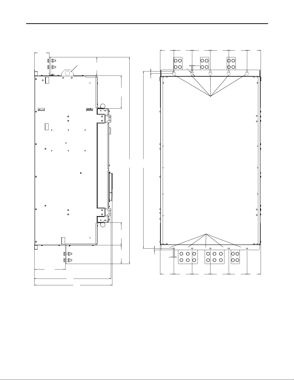
Dimensions are shown in mm and (in.)
Mounting holes
Mounting holes
Lifting flange
Installation and Wiring Chapter 1
Figure 6 - Frame D Dimensions - Left Side and Back Views
Rockwell Automation Publication 20P-UM001K-EN-P - July 2014 23
Page 24

Chapter 1 Installation and Wiring
Table 4 - Frame D - 230V AC Input Drive Weights
Drive w/ND
Rating Code
875
1K0
Weight - Regenerative Drives Weight - Non-regenerative Drives
Drive Drive and Packaging Drive Drive and Packaging
kg (lb) kg (lb) kg (lb) kg (lb)
203 (447.5) 281 (619.5) 152 (335.1) 230 (507.1)
Table 5 - Frame D - 460V AC Input Drive Weights
Drive w/ND
Rating Code
830
996
1K1
1K4
Weight - Regenerative Drives Weight - Non-regenerative Drives
Drive Drive and Packaging Drive Drive and Packaging
kg (lb) kg (lb) kg (lb) kg (lb)
202 (445.3) 280 (617.3) 152 (335.1) 230 (507.1)
215 (474.0) 293 (646.0) 165 (363.8) 243 (535.7)1K3
Table 6 - Frame D - 575V AC Input Drive Weights
Drive w/ND
Rating Code
810
1K0
1K2 215 (474.0) 293 (646.0) 165 (363.8) 243 (535.7)
1K3 222 (489.4) 300 (661.4) 172 (379.2) 250 (551.2)
1K6 241 (531.3) 319 (703.3) 191 (421.1) 269 (593.0)
Weight - Regenerative Drives Weight - Non-regenerative Drives
Drive Drive and Packaging Drive Drive and Packaging
kg (lb) kg (lb) kg (lb) kg (lb)
198 (436.5) 276 (608.5) 148 (326.3) 226 (498.2)
Table 7 - Frame D - 690V AC Input Drive Weights
Drive w/ND
Rating Code
678
791
904 200 (440.9) 278 (612.9) 150 (330.7) 228 (502.7)
1K0 202 (445.3) 280 (617.3)
1K1
1K2 165 (363.8) 243 (535.7)
1K4
1K5 191 (421.1) 269 (593.0)
24 Rockwell Automation Publication 20P-UM001K-EN-P - July 2014
Weight - Regenerative Drives Weight - Non-regenerative Drives
Drive Drive and Packaging D rive Drive and Packaging
kg (lb) kg (lb) kg (lb) kg (lb)
198 (436.5) 276 (608.5) 148 (326.3) 226 (498.2)
215 (474.0) 293 (646.0)
241 (531.3) 319 (703.3)
152 (335.1) 230 (507.1)
172 (379.2) 250 (551.2)
Page 25

Installation and Wiring Chapter 1
IMPORTANT
Lifting PowerFlex DC Drives
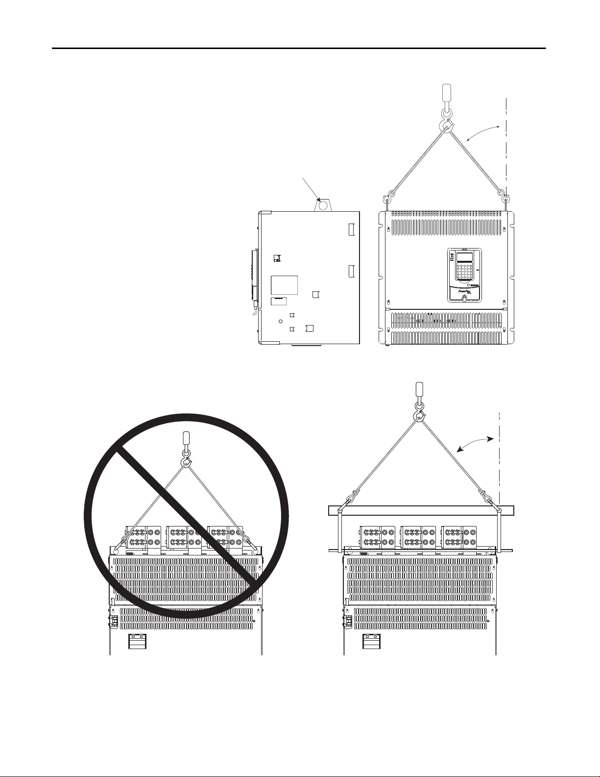
The dimensions and weights that are specified in Ta b l e 3 on page 21 and
Ta b l e 4
the proper equipment to lift and hold the weight of the drive while mounting.
…Ta b l e 7 on page 24 must be considered when mounting the device. Use
ATTENTION: To guard against possible personal injury or equipment damage...
• Inspect all lifting hardware for proper attachment before lifting the drive.
• Do Not let any part of the drive or lift mechanism to contact electrically charged
conductors or components.
• Do Not subject the drive to high rates of acceleration or deceleration while
transporting to the mounting location or when lifting.
• Do Not let personnel or their limbs be directly underneath the drive when it is
being lifted and mounted.
Mount Frame C and D Drives
All lifting equipment and components (hooks, bolts, lifts, slings, and chains)
must have a minimum
lifting capacity of 453.6 kg (1,000 lb).
Verify that all mounting screws are properly tightened before and after drive
operation.
1. Verify the hole pattern on the panel on which you intend to mount the
drive. See Figure 4
2. Install the mounting hardware:
❏ For frame C drives, insert, but do not tighten, a bolt in one of the top
holes in the panel. The bolt must be fully threaded into the panel
before hanging the drive.
❏ For Frame D drives, insert, but do not tighten, the six bolts for the top
mounting flange on the drive into the panel. The bolts must be fully
threaded into the panel before hanging the drive.
3. To limit the pull in forces on the drive, the lifting devices that are
connected to the hooks must be long enough to make the angle between
the chain or cable and a vertical line that extends up from the flange center
less than 45° angle as illustrated in Figure 7
26
.
❏ For frame C drives, insert the properly sized and rated lifting hooks
into the holes on the lifting flanges at the top of the drive. See Figure 7
on page 26
❏ For frame D drives, insert the properly sized lifting rod into the holes
on the lifting flanges at the top of the drive. See Figure 8
on page 21 or 22 on page 22.
on page 26 or Figure 8 on page
.
on page 26.
Rockwell Automation Publication 20P-UM001K-EN-P - July 2014 25
Page 26
Chapter 1 Installation and Wiring
Lifting flanges
Must be less
than 45° angle
Must be less
than 45° angle
Figure 7 - Lift Frame C Drives
Figure 8 - Lift Frame D Drives
4. Lift the drive into place onto the bolts that are installed in the panel.
5. Install the remaining bolts into the panel. Tighten M8 bolts to a minimum
torque of 15 N
N
•m (221.2 lb•in).
26 Rockwell Automation Publication 20P-UM001K-EN-P - July 2014
•m (132.7 lb•in) and M10 bolts to a minimum torque of 25
Page 27
Installation and Wiring Chapter 1
Remove the Drive Covers
Some protective covers must be removed to provide access to the power and I/O
terminals on the drive. Remove the upper cover only to install an optional
communication adapter or service the drive. See Installing a Communication
Adapter on page 367
for information.
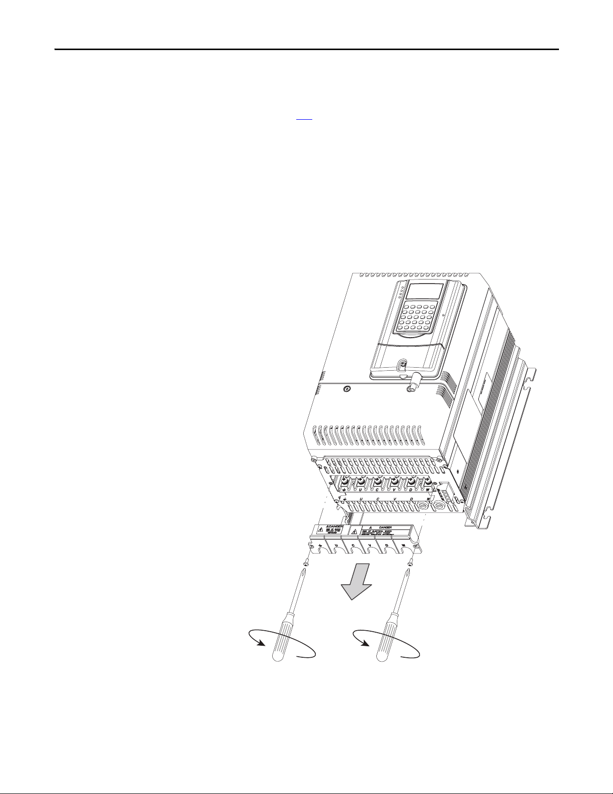
Frame A Drives
You must remove both the lower protective cover and the power terminal cover
on frame A drives to access the power terminals.
Remove the Power Terminal Cover
• Remove the two screws as shown here and slide the cover down and off the
chassis.
Rockwell Automation Publication 20P-UM001K-EN-P - July 2014 27
Page 28
Chapter 1 Installation and Wiring
STS
PORT
MOD
NET A
NET B
Frame B Shown
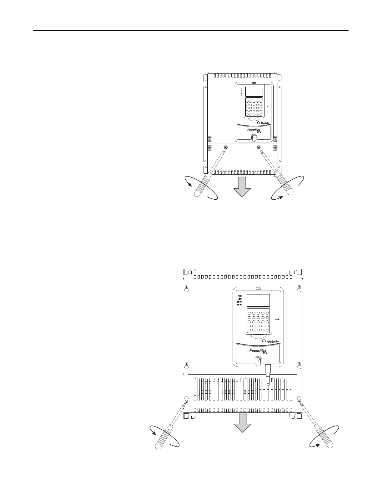
Remove the Lower Protective Cover
• Remove the two screws as shown here and, while gently lifting along the
top edge, slide the cover down and off the chassis.
Frame B and C Drives
1. Loosen, but do not remove, the two screws that secure the bottom cover.
2. Slide the cover down until the screw heads align with the key holes and lift
the cover off the chassis.
28 Rockwell Automation Publication 20P-UM001K-EN-P - July 2014
Page 29
Installation and Wiring Chapter 1
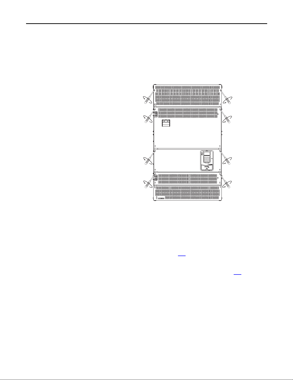
Frame D
1. For any protective cover, loosen, but do not remove, the hexalobular head
screws that secure the cover to the drive frame.
2. Slide the cover up until the screw heads align with the key holes and lift the
cover off the chassis. The top and bottom most covers are also secured with
screws at the top and bottom of the drive, respectively.
Isolation Transformers / Line Reactors
When connecting the drive directly to the main distribution system, an isolation
transformer or 3…5% impedance AC line reactor must be used to guard against
system disturbance. If the isolation transformer provides the required 3…5%
impedance, a line reactor is not required.
See Isolation Transformers on page 256
transformers.
See AC Input Line Reactors and AC Input Contactors on page 254
recommended AC line reactors. The type of line reactor that is used depends
upon the following:
• Current absorbed by the AC input
• AC input voltage
• Relative short circuit voltage
• AC input frequency
for a list of recommended isolation
for a list of
Rockwell Automation Publication 20P-UM001K-EN-P - July 2014 29
Page 30

Chapter 1 Installation and Wiring
Contactors
When an AC input contactor is used, the IEC AC1 rating of the contactor must
be equal to the rated thermal (RMS) current value at the main input of the drive.
Drive configurations for AC or DC contactors, with or without a dynamic brake
(DB), are as follows (see Typical Power Wiring Diagrams on page 45
for
examples):
• When only an AC contactor is used:
❏ Set parameter 1391
(1)
value)
[ContactorControl] to 1 “AC Cntctr” (default
❏ Set one [Relay Out x Sel] parameter and one [Digital Inx Sel]
parameter to “Contactor” (default value for parameters 1392
Out 1 Sel] and 140
[Digital In8 Sel])
[Relay
• When only a DC contactor is used:
❏ Set parameter 1391
[ContactorControl] to 3 “DC Cntctr”
(1)
❏ Set one [Relay Out x Sel] parameter and one [Digital Inx Sel] to
“Contactor” (default value for parameters 1392
[Digital In8 Sel])
140
[Relay Out 1 Sel] and
• When an AC contactor and dynamic brake contactor are used:
❏ Set parameter 1391
[ContactorControl] to “AC Cntctr+DB”
❏ Set one [Relay Out x Sel] parameter (1392 [Relay Out 1 Sel] or 629
[Relay Out 2 Sel]) to “Contactor” and the other relay output to
“ContactorDB”
❏ Set one [Digital Inx Sel] parameter to “Contactor” (default value for
parameter 140
[Digital In8 Sel])
• When a DC contactor and dynamic brake contactor are used:
❏ Set parameter 1391
[ContactorControl] to “DC Cntctr+DB”
❏ Set one [Relay Out x Sel] parameter (1392 [Relay Out 1 Sel] or 629
[Relay Out 2 Sel]) to “Contactor” and the other relay output to
“ContactorDB”
❏ Set one [Digital Inx Sel] parameter to “Contactor” (default value for
parameter 140
[Digital In8 Sel])
• When a contactor is NOT used:
❏ Set parameter 1391
[ContactorControl] to “None”
(1)
❏ Do NOT set either [Relay Out x Sel] parameter to “Contactor” or
“ContactorDB”
(1)
(1)
❏ Do NOT set any [Digital Inx Sel] parameter to “Contactor”
(1) Par 1391 [ContactorControl] is contained in the “Advanced” parameter configuration group. See How Parameters are Organized on
page 115
for more information.
30 Rockwell Automation Publication 20P-UM001K-EN-P - July 2014
Page 31

Installation and Wiring Chapter 1
When operating a drive with firmware version 1.006 in field weakening mode
with a DC contactor or inverting fault device that is installed in the armature
circuit, see Field Weakening Mode Configuration (v1.006) on page 285
.
AC Input Contactors
See AC Input Line Reactors and AC Input Contactors on page 254 for a list of
recommended AC input contactors.
DC Output Contactors
A DC output contactor can be used to connect the output of the armature circuit
to the DC motor. If a DC output contactor is used, an AC input contactor is not
needed.
See Dynamic Brake Resistor Kits and DC Output Contactors on page 258
list of recommended DC output contactors.
for a
Dynamic Brake Resistors
See Dynamic Brake Resistor Kits and DC Output Contactors on page 258 for a
list of recommended dynamic brake resistor kits.
Rockwell Automation Publication 20P-UM001K-EN-P - July 2014 31
Page 32

Chapter 1 Installation and Wiring
L1
L2
L3
U
V
W
C
D
PE1/
STS
PORT
MOD
NET A
NET B
Earth
All wires (including motor
ground) must be connected
inside the motor terminal box.
Transformer
Safety
Ground
AC Mai ns Supp ly
AC Line Reactor
General Grounding Requirements
The drive Safety Ground (PE) must be connected to system ground. Ground
impedance must conform to the requirements of national and local industrial
safety regulations and electrical codes. Periodically check the integrity of all
ground connections.
For installations within a cabinet, use a safety ground point or ground bus bar
connected directly to building steel. Ground all circuits, including the AC input
ground conductor, independently and directly to this point/bar.
For installations in distribution systems that have ungrounded or high
impedance, neutral connections or systems, see Grounding for Installations in an
Ungrounded or High-Impedance, Neutral Ground, or System on page 34
.
ATTENTION: To comply with the essential requirements of the CE Low Voltage
Directive 2006/95/EC, PowerFlex DC drives cannot be powered from a cornerearthed (TN with one phase earthed) supply system. When operating PowerFlex
DC drives from an IT or impedance-earthed supply system, only temporary
operation is permitted after an earth fault is detected in the power system.
Figure 9 - Typical Grounding
32 Rockwell Automation Publication 20P-UM001K-EN-P - July 2014
Page 33

Installation and Wiring Chapter 1
Safety Ground (PE)
The safety ground for the drive that is required by code. This point must be
connected to adjacent building steel (girder, joist), a floor ground rod, or bus bar
(see Figure 9
industrial safety regulations and electrical codes.
on page 32). Ground points must comply with national and local
Power Feeder
Each power feeder from the substation transformer to the drive must be provided
with properly sized ground cables. Bond the conduit or cable armor to the
substation ground at both ends. Each transformer enclosure or frame must be
bonded to ground at a minimum of two locations.
Encoder/Resolver Ground Connections
If used, the encoder or resolver ground connections must be routed in grounded
steel conduit. The conduit must be grounded at both ends. The encoder/resolver
cable shield must be connected to the shield ground on the drive side. Do not
connect the encoder/resolver cable shield to ground on the motor side.
Tachometer Ground Connections
If used, ground connections must be routed in grounded steel conduit. The
conduit must be grounded at both ends. Ground the cable shield at the drive end
by using only the shield clamps on the grounded metal plate that supports the
control board (see Figure 58
on page 81 for shield clamp location).
Rockwell Automation Publication 20P-UM001K-EN-P - July 2014 33
Page 34

Chapter 1 Installation and Wiring
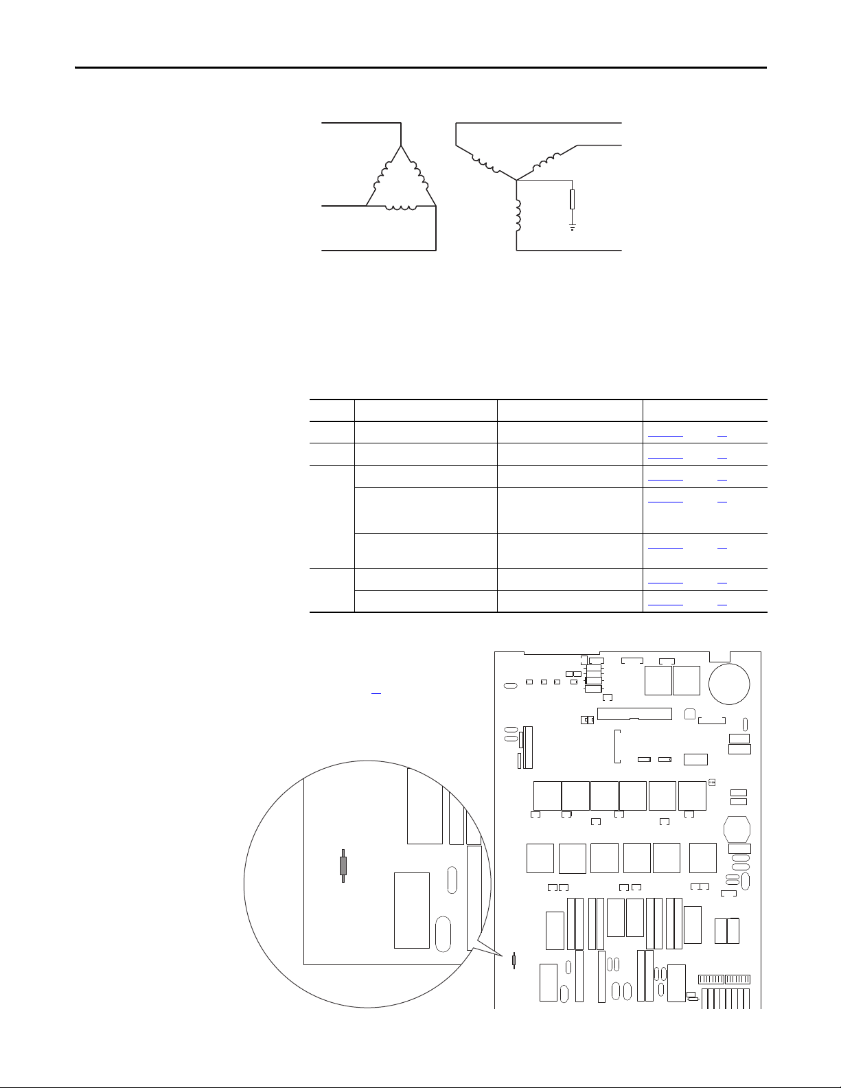
Grounding for Installations
in an Ungrounded or HighImpedance, Neutral Ground,
or System
The PowerFlex DC drive was designed to work in distribution systems where the
isolation transformer Wye neutral is connected to earth ground. PowerFlex DC
drives are not designed to work in distribution systems that have ungrounded or
high-impedance, neutral connections, or systems that have a phase that is
referenced to earth. Symmetrical incoming power is required for correct drive
operation.
The use of a grounded Wye neutral is highly recommended to prevent common
mode rejection problems with the feedback measurement circuits in the drive.
Possible drive damage can occur because of inaccurate feedback measurements of
the incoming AC voltage, armature voltage, or field current.
If the PowerFlex DC drive is installed in a system with an ungrounded Wye
neutral or with an impedance ground connection, see Ta b l e 8
necessary drive modifications that are required for proper installation.
on page 35 for the
Power Distribution
Figure 10 - Delta/Wye with Grounded Wye Neutral
Rockwell Automation strongly recommends the use of grounded neutral systems
for the following reasons:
• Controlled path for common mode noise current
• Consistent line to ground voltage reference, which minimizes insulation
stress
• Accommodation for system-surge protection schemes
Figure 11 - Ungrounded Secondary
Grounding the transformer secondary is essential to the safety of personnel and
safe operation of the drive. A floating secondary can allow dangerously high
voltages occur between the chassis of the drive and the internal power structure
components.
34 Rockwell Automation Publication 20P-UM001K-EN-P - July 2014
Page 35
Installation and Wiring Chapter 1
S9
T01 T04 T02 T05
T03
T06
T1 T4 T2 T5 T3 T6
78 79 35 36 75 76 U2 V2
S4
S3
XY
XR
TR2 TR1
XP
XSW
XSW1
X3
X4
S9
Note: Remove the front covers from the
drive to access the pulse transformer circuit
board. See page 27
for instructions.
Figure 12 - High-impedance Ground
Grounding the Wye secondary neutral through a resistor is an acceptable method
of grounding. In this case, in a short-circuited secondary condition, none of the
output phases to ground will exceed the normal line to line voltage. The resistor
is often used to detect ground current by monitoring the associated voltage drop.
Table 8 - Drive Modifications to Support Ungrounded Wye Neutral or Impedance Grounded
Connections
Frame Circuit Board Jumper/Connection Figure to see for Details
A Pulse transformer (FIR1-xx-xx) Remove jumper S9 Figure 13
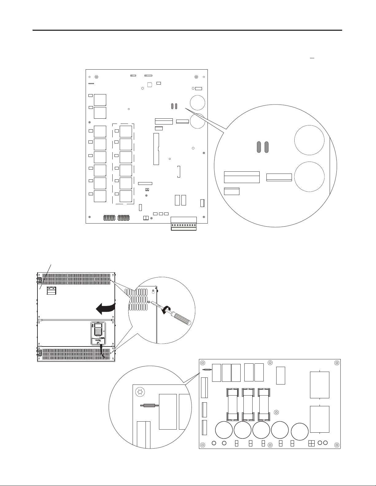
B Pulse transformer (FIR2-xx-xx) Remove jumper S9 Figure 1 4 on page 36
C Pulse transformer (FIR3-xx-xx) Remove jumper S9 Figu re 15 on page 36
Transient noise filter (FIL-31),
200V…500V AC drives
Disconnect the filter board yellow/
green (ground) wire from the PE
connection on the drive chassis
Transient noise filter (FIL-57,
Remove jumper S1 Figure 17 on page 37
FIL-69), 575V…690V AC drives
D Pulse transformer (FIR-D-xx-xx) Remove capacitors C121 and C122 Figure 18 on page 38
Overvoltage clipping (CFSF-xxx) Remove jumper S1 Figure 1 9 on page 38
on page 35
Figure 1 6 on page 37
Figure 13 - Frame A Pulse Transformer Circuit Board S9 Jumper Location
Rockwell Automation Publication 20P-UM001K-EN-P - July 2014 35
Page 36

Chapter 1 Installation and Wiring
S9
PE
XCD_IO
XTA
78 79 35 36 75 76 U2 V2
T01
T4
T1
T2
T02
T5
T3
T6
T03
T06
T04
T05
TR1
TR2
S9
PE
Note: Remove the front covers from the
drive to access the pulse transformer circuit
board. See page 28
for instructions.
X3
XCD_IO
TO5
TO3
TO6
TO2
KGO2
KGO5
KGO3 KGO6
T5 T3
T6
T2
KG2
KG5
KG3
KG6
XCT
PE
PE1
XCD
S3
S4
XUVW
1
1
XTA
TR3
XR
S9
XCD_IO
PE
PE1
XCD
S9
Note: The pulse transformer circuit board is behind the control EMI shield, near the top of the drive. See page 28 for
instructions on removing the front covers from the drive and page 68
for instructions on moving the control EMI shield.
Figure 14 - Frame B Pulse Transformer Circuit Board S9 Jumper Location
Figure 15 - Frame C Pulse Transformer Circuit Board S9 Jumper Location
36 Rockwell Automation Publication 20P-UM001K-EN-P - July 2014
Page 37

Installation and Wiring Chapter 1
STS
PORT
MOD
NET A
NET B
U
V
C
Yellow/Green ( ground) wire
Transient noise filter board
Note: Remove the front covers from the drive to access the transient noise filter circuit board. See page 28 for
instructions. The transient noise filter board is between terminals C and D below the control EMI shield.
Note: Remove the front covers from the drive to access the transient noise filter circuit board. See page 28 for
instructions. The transient noise filter board is on the left side of the control EMI shield.
Figure 16 - Frame C Transient Noise Filter Circuit Board (FIL-31), 200V…500V AC Input Drives,
Ground Wire Location
Figure 17 - Frame C Transient Noise Filter Circuit Board (FIL-57, FIL-69), 575V…690V AC Input
Drives, S1 Jumper Location
P4 P3
S1
F1 F2 F3
S1
Rockwell Automation Publication 20P-UM001K-EN-P - July 2014 37
Page 38
Chapter 1 Installation and Wiring
Note: The pulse transformer circuit board is behind the top and bottom control panel covers. See page 29 for
instructions on removing the covers from the drive.
90°
Note: The overvoltage clipping circuit board is behind the control panel on the upper left side of
the drive chassis. See illustration below, left for instructions on opening the control panel.
Overvoltage clipping board
location inside drive
1. Disconnect the DPI cable from the HIM (if present).
2. Insert a flathead screwdriver into the holes in the right side of the protective
covers on the drive and turn the latch 90° counter-clockwise.
3. Open the control panel to the left.
PE
XP1
XP2
KG1
KG4
KG2
KG5
KG3
KG6
Figure 18 - Frame D Pulse Transformer Circuit Board S1 Jumper Location
XSW1
XSW
X3
TR2
C122 C121
TR1
KG01
T1
T4
T2
T5
T3
T6
T01
KG04
T04
KG02
T02
KG05
T05
KG03
T03
KG06
T06
XTA
S3
S4
XCD_IO
XCD
XR
XY
X4 X5 X6
XCT
XUVW
XUV
C122 C121
XCD_IO
XSPF
XUVW
78 79 35 36 75 76 81 82 U2 V2
Figure 19 - Frame D Overvoltage Clipping Circuit Board S1 Jumper Location
S1
XCD
F31 F21 F11
S1
X1UVW1
XUVW
XCD
38 Rockwell Automation Publication 20P-UM001K-EN-P - July 2014
Page 39

Installation and Wiring Chapter 1
CE Conformity
Compliance with the Low Voltage Directive and Electromagnetic Compatibility
Directive has been demonstrated by using harmonized European Norm (EN)
standards, references to which have been published in the Official Journal of the
European Communities. PowerFlex DC drives comply with the EN standards
listed here when installed according to this User Manual.
EU Declarations of Conformity are available online at:
www.rockwellautomation.com/products/certification/ce/
Low Voltage Directive
• EN 50178 Electronic equipment for use in power installations.
EMC Directive
• EN 61800-3 Adjustable speed electrical power drive systems Part 3: EMC
product standard including specific test methods.
General Considerations
• For CE compliance, the drive installation must satisfy requirements that are
related to both EN 50178 and EN 61800-3 provided in this document.
• PowerFlex DC drives comply with the EMC requirements of EN 61800-3
when installed according to good EMC practices and the instructions that are
provided in this document. However, many factors can influence the EMC
compliance of an entire machine or installation, and compliance of the drive
itself does not ensure compliance of all applications.
• PowerFlex DC drives are not intended to be used on public low-voltage
networks that supply domestic premises. Without additional mitigation,
radio frequency interference is expected if used on such a network. The
installer is responsible to take measures such as supplementary line filters and
enclosures to prevent interference, in addition to the installation requirements
of this document.
• PowerFlex DC drives generate notching and harmonic current emissions on
the AC supply system. When operated on a public low-voltage network, it is
the responsibility of the installer or user to be sure that applicable
requirements of the distribution network operator have been met.
ATTENTION: PowerFlex DC drives can produce DC current in the protective
earthing conductor, which can reduce the ability of residual current-operated
protective devices (RCD) or residual current-operated monitoring devices (RCM),
of type A or AC, to provide protection for other equipment in the installation.
Rockwell Automation Publication 20P-UM001K-EN-P - July 2014 39
Page 40
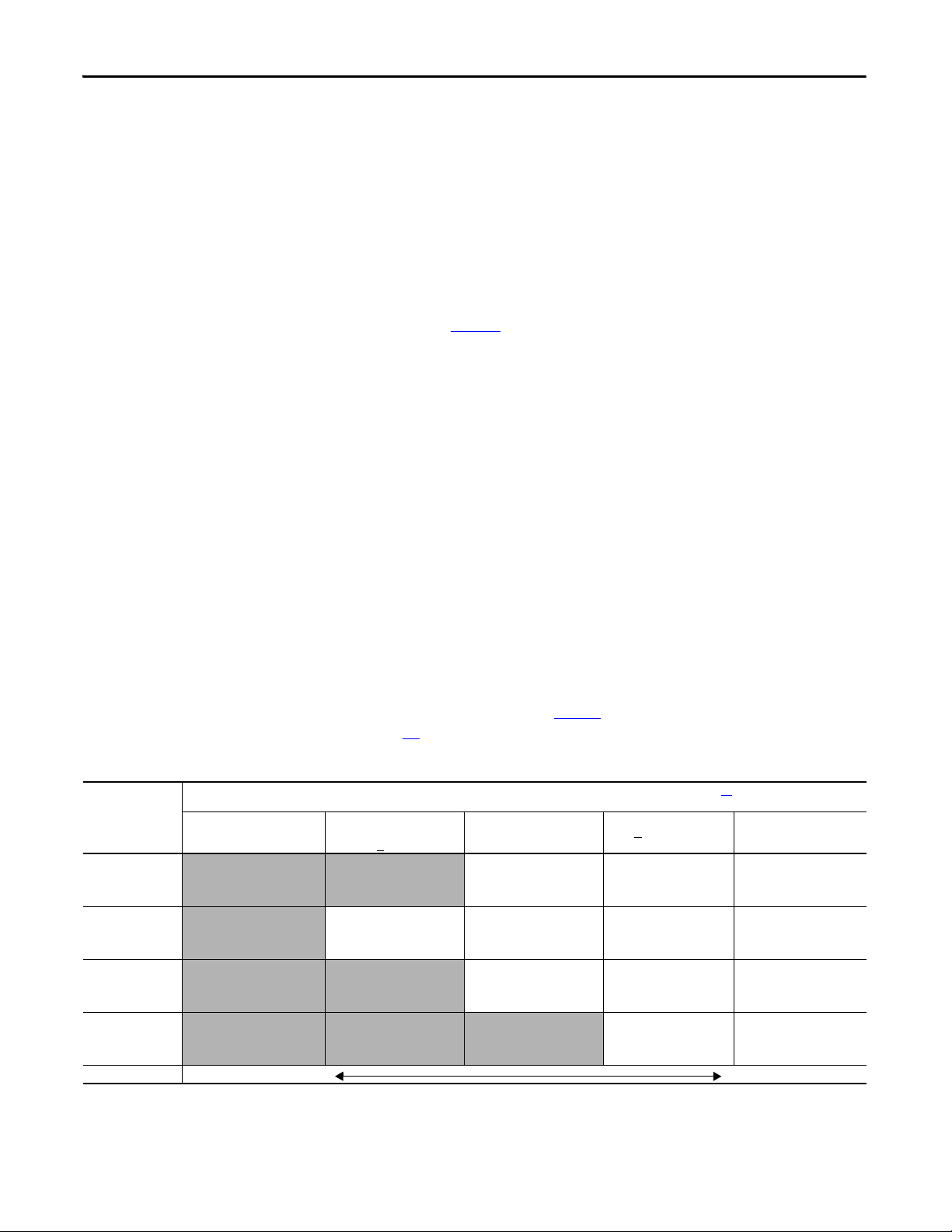
Chapter 1 Installation and Wiring
Installation Requirements Related to the Low Voltage Directive
• PowerFlex DC drives are designed to be CE compliant only if they are NOT
connected to “corner-earthed” supply systems where one of the three phases of
the supply system has been earthed.
• PowerFlex DC drives are compliant with the CE LV Directive when used at
altitudes no greater than 2,000 m (6,562 ft).
• PowerFlex DC drives provided in enclosure type IP20 must be installed in a
pollution degree 1 or 2 environment to be compliant with the CE LV
Directive. Characteristics of the different pollution degree ratings are
provided on page 41
• PowerFlex DC drives can produce leakage current in the protective earthing
conductor that exceeds 3.5 mA AC or 10 mA DC. The minimum size of the
protective earthing (ground) conductor that is used in the application must
comply with local safety regulations for high-protective earthing conductor
current equipment.
• Frame D PowerFlex DC drives must be installed in a supplementary enclosure
that provides protection from electric shock to be compliant with the CE LV
Directive.
.
Drive Frame
Catalog Number
Frame A
20Px1Ax4P1…
20Px1Ax129
Frame B
20Px1Ax167…
20Px1Ax412
Frame C
20Px1Ax495…
20Px1Ax667
Frame D
20Px1Ax…
20Px1Ax
Installation Requirements Related to EN 61800-3 and the EMC Directive
• The drive must be earthed (grounded) as described in this User Manual.
• PowerFlex DC drives require the use of an external EMC filter to comply with
the EMC Directive and emission limits of EN 61800-3: 2004. PowerFlex DC
drives have been tested and verified for compliance to the emission limits of
EN 61800-3: 2004 by using only the specific input filters and motor cable
lengths that are identified in Ta b l e 9
page 45
Table 9 - Standards and Limits for EMC Input Filters
Standard / Limits (Compliance with any of the limits in the Pollution Degree Ratings According to EN 61 800-5-1 table on page 41 satisfies RF emission
requirements for the EMC Directive)
EN61800-3 Category C1
EN61000-6-3 CISPR 11 Group 1
Class B
Compliance may be possible
with supplementary mitigation
(Consult fac tory)
Compliance may be possible
with supplementary mitigation
(Consult fac tory)
Compliance may be possible
with supplementary mitigation
(Consult fac tory)
Compliance may be possible
with supplementary mitigation
(Consult fac tory)
More Stringent Limits Less St ringent Limits
EN61800-3 Category C2
EN61000-6-4 CISPR11 Group 1
Class A…P <
Compliance may be possible
with supplementary
mitigation (Consult factory)
RF line filter required
50 m motor cable limit
Compliance may be possible
with supplementary
mitigation (Consult factory)
Compliance may be possible
with supplementary
mitigation (Consult factory)
for more installation information.
CISPR11 Group 1
20kVA
(1)
Class A…P > 20kVA
RF line filter required
50 m motor cable limit
RF line filter required
50 m motor cable limit
RF line filter required
50 m motor cable limit
Compliance may be possible
with supplementary
mitigation (Consult factory)
. See Typical Power Wiring Diagrams on
EN61800-3 Category
C3…I <
100A
(2)
(1)
(1)
RF line filter required
50 m motor cable limit
RF line filter required
50 m motor cable limit
RF line filter required
50 m motor cable limit
RF line filter required
50 m motor cable limit
EN61800-3 Category
C3…I > 100A
(2)
RF line filter required
50 m motor cable limit
(1)
RF line filter required
50 m motor cable limit
(1)
RF line filter required
50 m motor cable limit
(3)
RF line filter required
50 m motor cable limit
(2)
(1)
(1)
(4)
(1) RF 3xxx-MHU EMC filter from Rasmi Electronics Ltd. xxx designates filter current rating. Rasmi EMC filters are manufactured by Rasmi Electronics Ltd. Refer to the manufacturer’s literature for details.
(2) RF 3xxx-SIEI EMC filter from Rasmi Electronics Ltd. xxx designates filter current rating. Rasmi EMC filters are manufactured by Rasmi Elec tronics Ltd. Refer to the manufacturer’s literature for details.
(3) EPCOS B84143B Type S081 EMC filter from EPCOS AG. EPCOS EMC filters are manufactured by EPCOS AG. Refer to the manufacturer’s literature for details.
40 Rockwell Automation Publication 20P-UM001K-EN-P - July 2014
Page 41

Installation and Wiring Chapter 1
IMPORTANT
Use of EMC filters other than those listed in Ta bl e 9 on page page 40 must be
verified in the application. Additional filters are listed in Alternate EMC Filters
on page 261
.
• Output power wiring to the motor must employ cable with a braided
shield providing 75% or greater coverage, or the cables must be housed in
metal conduit, or equivalent shielding must be provided. Continuous
shielding must be provided from the drive enclosure to the motor
enclosure. Both ends of the motor cable shield (or conduit) must terminate
with a low-impedance connection to earth.
• At the motor end, the motor cable shield or conduit must terminate in a
shielded connector that must be properly installed in an earthed motor
wiring box attached to the motor. The motor wiring box cover must be
installed and earthed.
• All control (I/O) and signal wiring to the drive must use cable with a
braided shield providing 75% or greater coverage, or the cables must be
housed in metal conduit, or equivalent shielding must be provided. When
shielded cable is used, terminate only the drive end of the cable shield to
earth with a low-impedance connection.
• Motor cabling must be separated from control and signal wiring wherever
possible.
• Maximum motor cable length must not exceed the maximum length
indicated in the table on page 40
for compliance with radio frequency
emission limits for the specific standard and installation environment.
Pollution Degree Ratings According to EN 61800-5-1
Pollution
Degree
1 No pollution or only dry, non-conductive pollution occurs. The pollution has no influence.
2 Normally, only non-conductive pollution occurs. Occasionally, however, a temporary conductivity caused
3 Conductive pollution or dry non-conductive pollution occurs, which becomes conductive due to
4 The pollution generates persistent conductivity caused, for example by conduc tive dust or rain or snow.
Description
by condensation is to be expected, when the drive is out of operation.
condensation, which is to be expected.
Rockwell Automation Publication 20P-UM001K-EN-P - July 2014 41
Page 42

Chapter 1 Installation and Wiring
Power Circuit Protection
Control Power Circuit Protection
It is recommended that you install frame A and B PowerFlex DC drives with fast
acting fuses to protect the armature converter on the AC input and DC output
(for four quadrant drives only) sides. Internally mounted fuses for armature
converter protection are provided with frame C and D PowerFlex DC drives. See
Drive Power Circuit Protection on page 236
for a list of replacement fuses and
general fuse locations.
The 115V / 230V AC control circuit power input terminals U2 and V2 are
required to be short circuit protected. This protection can be provided by using
standard time delay fuses or a circuit breaker. The time delay fuses or circuit
breaker must be selected to survive the short circuit available current of the feeder
source for this circuit and the inrush current of the drive’s power supply.
Size the fuses or circuit breaker to primarily protect the wiring from the fuses or
circuit breaker connections to terminals U2 and V2, and not nuisance trip or
blow from the inrush current.
The table below lists the input current characteristics of the control power.
Table 10 - Control Power Protection
Frame Control Power Supply
Circuit Board ID / Revision Power Rated input current Inrush input current
115V AC 230V AC 115V AC 230V AC
A & D SW1-31 / H & below 60 W 1 A 0.5 A 20 A 10 A
SW1-31 / I & above 80 W 1 A 0.5 A 6 A 10 A
B SW2-32 / H & below 110 W 1.2 A 0.7 A 15 A 7.5 A
SW2-32 / I & above 90 W 1.2 A 0.6 A 6 A 10 A
C SW3-32 / H & below 110 W 1.2 A 0.7 A 15 A 7.5 A
SW3-32 / I & above 90 W 1.2 A 0.6 A 6 A 10 A
Provide a control power input supply from a power source that is stabilized and
buffered from the power system transients. The control power of many drives can
be fed from a single source, as long as proper distribution protection is provided.
42 Rockwell Automation Publication 20P-UM001K-EN-P - July 2014
Page 43

Installation and Wiring Chapter 1
Minimum Spacing Between Classes Steel Conduit/Tray
Category
Wiri ng
Class
Signal Definition Signal Example 1
2/3/4 5/6
Power
2
AC Power (le ss
than 600V)
460V 3/Ph AC Lines 3/6 in.
(76/152 mm)
Control
6
24V AC/DC Logic PLC I/O 3/6 in.
(76/152 mm)
Cable and Wiring Recommendations
Category Wiring
Power 1 AC Power (600V Or
Control 5 115V AC/ DC Logic Relay Lo gic/PLC I/O
Signal
(Process)
Signal
(Comm. )
Signal Definition Signal Example Cable Type 1 2/3/4 5/6 7/8 9/10/11 See Cable
Class
Greater)
2AC Power (Less Than
600V)
3 DC Power DC Motor Armature
4 DC Power DC Motor Field
115V AC Power Power Supplies,
6 24V AC/DC Logic PLC I/O
7 Analog Signals, DC
Supplies
Digital (Low Speed) TTL
8 Digital (High Sp eed) I/O, Encoder, Resolver,
9 Serial Communication RS-232 (20-COMM-R),
11 Seri al Communication
(Greater Than 20k Baud)
2.3kV 3/ph AC Lines Per NEC & Local
460V 3/ph AC Lines 3/9 in.
Motor Thermostat
Instruments
Reference/Feedback
Signal, 5 To 24V DC
Count Pulse Tach
42 2 To Term ina ls /pr in ter s
PLC Remote I/O, PLC Data
Highway
Use the following cable and spacing recommendations for all drives sizes:
Minimum Spacing Between Classes - Steel Conduit/Tray
Notes, on
Codes
Shielded Cable –
Belden 8735,
8737, 8404
Shielded Cable –
Belden 9728, 9730
Shielded Cable –
Belden RS-232 –
8735, 8737 RS422 – 9729, 9730
Twi nax ial Cab le –
Belden 9463, A-B
1770-CD
03/9 in.
(76/229 mm)
(76/229 mm)
3/9 in.
(76/229 mm)
3/18 in.
(76/457 mm)
03/6 in.
3/6 in.
(76/152 mm)
3/12 in.
(76/305 mm)
See Note 6 1/3 in.
3/9 in.
(76/229 mm)
(76/152 mm)
03/9 in.
3/9 in.
(76/229 mm)
3/18 in.
(76/457 mm)
3/12 in.
(76/305 mm)
(76/229 mm)
01/3 in.
(25/76 mm)
See Note 6 1/2/5
See Note 6 1/2/5
See Note 6 1/2/5
(25/76 mm)
0–
Spacing
page 44
2/3/4/5
Example:
Spacing relationship between 480V AC incoming power leads and 24V DC logic
leads:
• 480V AC leads are Class 2; 24V DC leads are Class 6
• For separate steel conduits, the conduits must be 3 inches (76 mm) apart
• In a cable tray, the two groups of leads are to be 6 inches (152 mm) apart
Rockwell Automation Publication 20P-UM001K-EN-P - July 2014 43
Page 44

Chapter 1 Installation and Wiring
Cable Spacing Notes:
1. Both outgoing and return current carrying conductors are to be pulled in same conduit or laid adjacent in tray.
2. Cables of the following classes can be grouped together.
a. Class 1; Equal to or above 601V.
b. Classes 2, 3 and 4 may have their respective circuits pulled in the same conduit or layered in the same tray.
c. Classes 5 and 6 may have their respective circuits pulled in the same conduit or layered in the same tray. Note:
Bundle may not exceed conditions of NEC 310.
d. Classes 7 and 8 may have their respective circuits pulled in the same conduit or layered in the same tray. Note:
Encoder cables run in a bundle may experience some amount of EMI coupling. The circuit application may dictate
separate spacing.
e. Classes 9, 10 and 11 may have their respective circuits pulled in the same conduit or layered in the same tray.
Communication cables run in a bundle may experience some amount of EMI coupling and corresponding
communication faults. The application may dictate separate spacing.
3. All wires of class 7 through 11 MUST be shielded per the recommendations.
4. In cable trays, steel separators are advisable between the class groupings.
5. If conduit is used, it must be continuous and composed of magnetic steel.
6. Spacing of communication cables classes 2…6 is:
Conduit Spacing: Through Air:
115V – 25 mm (1 in.) 115V – 51 mm (2 in.)
230V – 38 mm (1.5 in.) 230V – 01.5 mm (4 in.)
380/575V – 76 mm (3 in.) 380/575V – 203 mm (8 in.)
575V– proportional to 152 mm (6 in.) per 1000V. 575V – proportional to 305 mm (12 in.) per 1000V.
Power Wiring
AC Input Voltages
PowerFlex DC drives are rated for the following AC input voltages @ 50/60 Hz
±5%:
Mains Circuit (Terminals U, V, W)
• 230V ±10%, 3Ph
• 400V ±10%, 3Ph
• 440V ±10%, 3Ph
• 460V ±10%, 3Ph
• 480V ±10%, 3Ph
• 575V ±10%, 3Ph
• 690V ±10%, 3Ph
Field Circuit (Terminals U1, V1)
• 230V ±10%, 1Ph
• 400V ±10%, 1Ph
• 460V ±10%, 1Ph
44 Rockwell Automation Publication 20P-UM001K-EN-P - July 2014
Page 45

Installation and Wiring Chapter 1
Control Circuit (Terminals U2, V2)
• 115V ±15% or 230V ±15%, 1Ph
Note: For frame B and C drives only, a jumper must be placed between terminals
SA-SB on the switching power supply circuit board for the control circuits to
work with 115V AC input. See Figure 47
on frame B drives and Figure 48
on page 68 for terminal block location on frame
on page 68 for terminal block location
C drives.
DC Output Voltages
The output voltages below take into account an AC input undervoltage within
the stated tolerance limits and a voltage drop of 4% due to an AC input line
reactor. It is the same as the rated armature voltage suggested for the connected
motor.
Armature Circuit
AC Input Voltage DC Output Armature Voltage (Terminals C & D)
(Terminals U, V, W) Two Quadrant Drive Four Quadrant Drive
230V ±10%, 3Ph 260V 240V
400V ±10%, 3Ph 470V 420V
440V ±10%, 3Ph 530V 460V
460V ±10%, 3Ph 560V 480V
480V ±10%, 3Ph 580V 500V
575V ±10%, 3Ph 680V 600V
690V ±10%, 3Ph 810V 720V
Field Circuit
AC Input Voltage DC Output Field Voltage
(Terminals U1 & V1) Fixed Field Adjustable Field
230V ±10%, 1Ph 200V 200V
400V ±10%, 1Ph 310V 310V
460V ±10%, 1Ph 360V 360V
(1) The max fiel d voltage is equal to 0.85 x AC input line voltage
(1)
(Terminals C1 & D1)
Typical Power Wiring Diagrams
Figure 20 on page 46…Figure 22 on page 48 represent recommended power
wiring configurations for standard PowerFlex DC drive installations. For SAR
installations, see Appendix H
Rockwell Automation Publication 20P-UM001K-EN-P - July 2014 45
.
Page 46
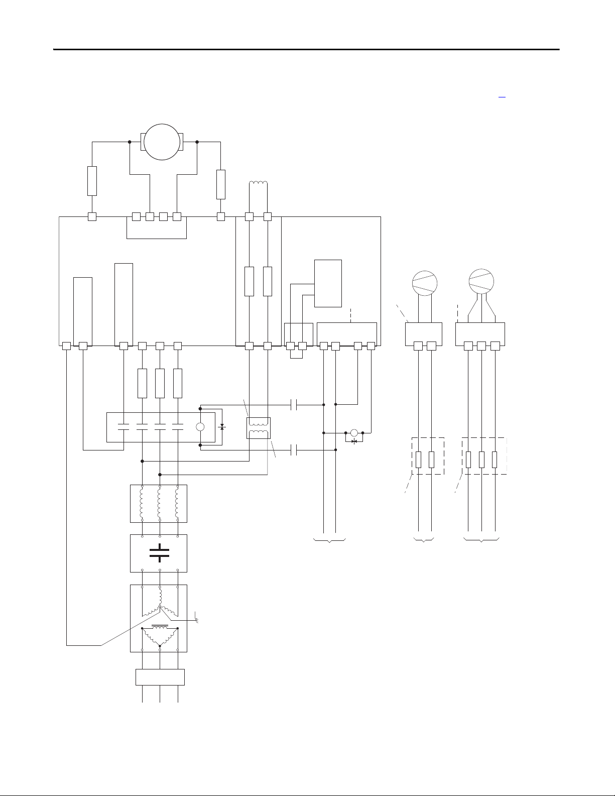
Chapter 1 Installation and Wiring
M
C
D
Aux
PowerFlex DC
Drive
36
(9)
34
(4)
(on I/O TB4)
19
(5)
(+24V on I/O TB2)
(N.O. Relay)
M1 AC Contactor
Control
Board P/S
115V or 230V AC
Input Source
(1, 12)
V2
U2
F2
A1
A2
35
(9)
U
V
W
L1
L2
L3
13 14
L1
L2
L3
A1
T1
T2
T3
A2
U1
V1
C1
D1
F1
FS2
(6)
FS2
(6)
FS1
(3)
FS1
(3)
FS1
(3)
FU1
FV1
Field Power Terminal Block
Control Power / Relay Outputs
Terminal Block
A1
A2
Armature Volt.
Fdbk. Term. Blk.
(7)
1A1
1A2
Line Reactor
(2)
Isolation
Transformer
(2)
Lockable
Installation
Disconnect
SB
(1)
SA
(1)
PE
Safety Ground
AC Input
Voltage
460 VAC
Max. or
230 VAC
Min.
(11)
EMC Filter
(if used)
K1
(14)
K1
(14)
K1
(14)
Fan Power Terminal Block - Series B ,Frame D Drives Only
(10)
400...460V AC
Input Source
(12)
See footnote
(13)
FUFUFU
U3V3W3
Fan Power Terminal Block - Frame C and Series A, Frame D Drives Only
(10)
230V AC
Input Source
(12)
See footnote
(13)
FU
FU
U3
V3
See Power Wiring Diagrams Notes on page 49 for footnotes.
Figure 20 - Power Wiring with AC Input Contactor
46 Rockwell Automation Publication 20P-UM001K-EN-P - July 2014
Page 47
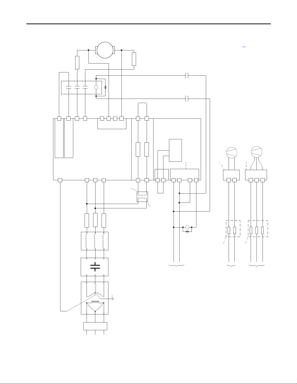
Aux
See Power Wiring Diagrams Notes on page 49 for footnotes.
Installation and Wiring Chapter 1
Figure 21 - Power Wiring with DC Output Contactor
M
A1
(6)
FS2
T1
T2
A2
L1
L2
13 14
A1
A2
(6)
FS2
(14)
(14)
K1
(10)
K1
(10)
(on I/O TB4)
(4)
34
PE
(+24V on I/O TB2)
(5)
19
C
PowerFlex DC
(3)
FS1
(2)
Line Reactor
D
U
(N.O. Relay)
M1 DC
Drive
(3)
FS1
FU1
FV1
F2
D1
V1
AC Input
Voltage
Control
Board P/S
Control Power / Relay Outputs
Terminal Block
(9)
(1)
(1)
U2
SB
SA
(9)
35
36
V2
(14)
K1
Fan Power Terminal Block - Frame C and Series A, Frame D Drives Only
U3
FU
(13)
Fan Power Terminal Block - Series B ,Frame D Drives Only
V3
U3V3W3
FU
FUFUFU
(13)
F1
Contactor
A1
A2
1A1
Armature Volt.
1A2
Fdbk. Term. Blk.
C1
Field Power Terminal Block
V
W
460 VAC
(3)
Max. or
(11)
Min.
230 VAC
U1
FS1
EMC Filter
(2)
Isolation
Lockable
Installation
(if used)
Transformer
Disconnect
L1
See footnote
(1, 12)
115V or 230V AC
Safety Ground
L2
L3
3 Phas e
AC l ine
Input Source
(12)
230V AC
Input Source
Rockwell Automation Publication 20P-UM001K-EN-P - July 2014 47
See footnote
400...460V AC
(12)
Input Source
Page 48

Chapter 1 Installation and Wiring
C
D
PowerFlex DC
Drive
36
(9)
34
(4)
(on I/O TB4)
19
(5)
(+24V - on I/O TB2)
Control
Board P/ S
U2
V2
F2
35
(9)
U
V
W
U1
V1
C1
D1
F1
FS1
(3)
FS1
(3)
FU1
FV1
Field Power Terminal Block
Control Power / Relay Ouputs
Terminal Block
A1
A2
Armature Volt.
Fdbk. Term. Blk.
1A1
1A2
Line Reactor
(2)
SB
(1)
SA
(1)
Aux
(N.O. Relay)
M1 DC Cntctr
13 14
L1
L2
L3
A1
T1
T2
T3
A2
M
A1
A2
FS2
(6)
FS2
(6)
DB
Res.
(8)
FS1
(3)
Isolation
Transformer
(2)
Safety Ground
PE
AC Input
Voltage
460 VAC
Max. or
230 VAC
Min.
(11)
3 Phas e
AC line
L1
L2
L3
Lockable
Installation
Disconnect
115V or 230V AC
Input Source
(1, 12)
EMC Filter
(if used)
K1
(14)
K1
(14)
K1
(14)
Fan Power Terminal Block - Series B ,Frame D Drives Only
(10)
400...460V AC
Input Source
(12)
See footnote
(13)
FUFUFU
U3V3W3
Fan Power Terminal Block - Frame C and Series A, Frame D Drives Only
(10)
230V AC
Input Source
(12)
See footnote
(13)
FU
FU
U3
V3
See Power Wiring Diagrams Notes on page 49 for footnotes.
Figure 22 - Power Wiring with DC Output/Dynamic Braking Contactor and a Dynamic Brake
48 Rockwell Automation Publication 20P-UM001K-EN-P - July 2014
Page 49

Installation and Wiring Chapter 1
Power Wiring Diagrams Notes
1. For frame B and C drives only, a jumper is required between terminals SA
and SB for 115V AC control input power. See Control Circuit Input
Power on page Control Circuit Input Power for more information.
2. An Isolation Transformer and/or 3…5% impedance Line Reactor is
required. If the Isolation Transformer provides the required 3…5%
impedance, a Line Reactor is not required. See AC Input Line Reactors
and AC Input Contactors on page 254
for recommendations. It is recommended that the isolation
256
transformer has a grounded Wye secondary neutral. If the PowerFlex DC
drive is installed in a system with an ungrounded Wye neutral or with an
impedance ground connection, see Grounding for Installations in an
Ungrounded or High-Impedance, Neutral Ground, or System on page 34
for more information.
3. AC input fuses for the armature converter are customer supplied for frame
A and B drives and are internally mounted on frame C and D drives. See
Drive Power Circuit Protection on page 236
4. Par 140 [Digital In8 Sel] set to 31 “Contactor.”
and Isolation Transformers on page
for fuse recommendations.
5. If the +24V internal power supply is used, terminal 18 (24V common)
must be jumpered to terminal 35 (digital input common).
6. Customer supplied armature output fuses are required on four quadrant
and are recommended on two quadrant Frame A and B drives. See Drive
Power Circuit Protection on page 236
for fuse recommendations.
7. Optional armature voltage feedback sensing not required with AC
contactor.
8. The “Enable” input must be removed to perform a dynamic braking stop.
9. Par 1391 [ContactorControl] = 1 “AC Cntctr” and Par 1392 [Relay Out
1 Sel] = 25 “Contactor”. Important: Terminal 35 and 36 are on the
Control Power / Relay Outputs Terminal block, NOT the I/O terminal
blocks. See Figure 37
on page 63…Figure 41 on page 65.
10. Only frame C and D drives require an external power supply for the
heatsink cooling fan(s). See Frame C Heatsink Cooling Fan Specifications
on page 69
page 71
11. See Field Converter Connections on page 56
and Frame D, Series B Heatsink Cooling Fan Specifications on
for more information.
.
12. If sourced from the main 3 phase AC input, the connections must be taken
from the primary side of the isolation transformer or line reactor (clean
power).
13. Fuses or a circuit breaker. See Frame C Heatsink Cooling Fan
Specifications on page 69
Specifications on page 71
and Frame D, Series B Heatsink Cooling Fan
for detailed information.
14. For frames B, C, and D drives, a pilot relay is required for the contactor
coil.
Rockwell Automation Publication 20P-UM001K-EN-P - July 2014 49
Page 50

Chapter 1 Installation and Wiring
IMPORTANT
UCV DWPE
Front View
ATTENTION: Do not operate the drive with the power terminal cover removed.
Operating the drive with the power terminal cover removed may result in a
hazardous condition that could cause personal injury and/or equipment
damage.
Note: Front view of drive shown with bottom protective and power terminal covers removed. See Remove the
Drive Covers on page 27
for information on removing the drive covers.
Armature Converter Connections
Terminals Description
U, V, W Three phase AC input to the armature converter
C, D DC output to the motor armature
PE Safety ground
Table 11 - Armature and Safety Ground (PE) Terminal Specifications
Drive Current Rating Code
230V 460V 575 690
Frame
A 7P0…055 4P1…052 – – U, V, W, C, D, PE
073…110 073…129 – – Terminal Block 12 (106)
B All All All – U, V, W, C, D 10 25 (221)
C All All All All U, V, W, C, D 10 25 (221)
D All All All All U, V, W, C, D, PE 12 45 (398.2)
(1)
Terminals Wire Size and Type Terminal Bolt
See Cable and Wiring
PE 8 15 (132.75)
PE 8 15 (132.75)
Recommendations on
page 43
Size (mm)
5 6 (53)
Tightening
Tor que
N•m (lb•in)
(1) Se e Standard Drive Catalog Number Explanation on page 15, positions 8, 9 and 10 for corresponding drive HP rating, armature amp rating and
field amp rating.
Certain frame D drives require the use of a terminal adapter kit(s) for terminals
U, V, W, C and D. See Terminal Adapter Kits for Frame D Drives on page 264
details.
Figure 23 - Frame A Armature Converter Terminal Locations
for
50 Rockwell Automation Publication 20P-UM001K-EN-P - July 2014
Page 51

Figure 24 - Frame B Armature Converter Terminal Locations
UCVDW
PE
UCVDW
PE
Bottom View
Front View
Figure 25 - Frame C Armature Converter Terminal Locations
Installation and Wiring Chapter 1
Rockwell Automation Publication 20P-UM001K-EN-P - July 2014 51
Page 52
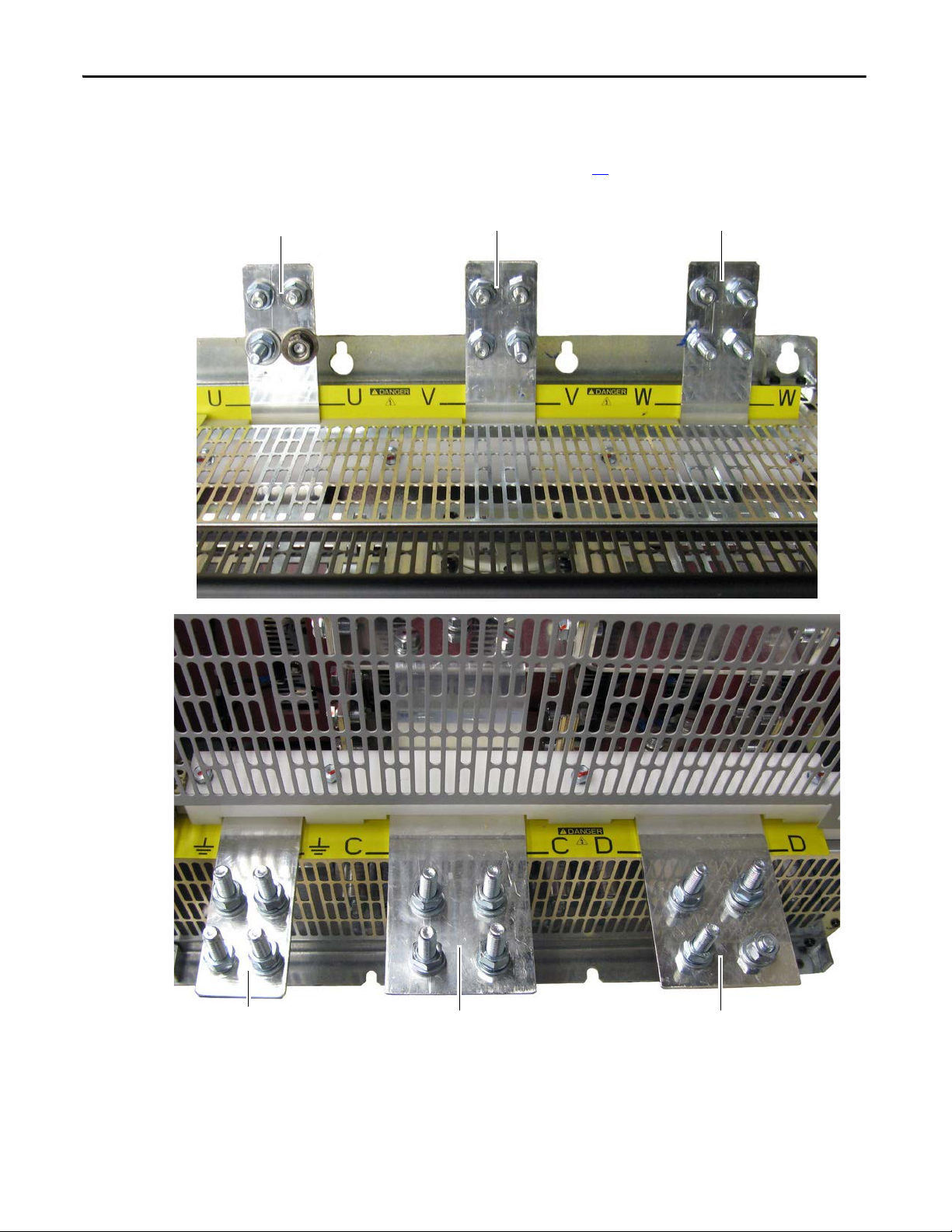
Chapter 1 Installation and Wiring
Top of Dr ive
UV W
Bottom of Drive PE C D
Important: Certain frame D drives require the use of a terminal adapter kit(s) for terminals
U, V, W, C and D. See Terminal Adapter Kits for Frame D Drives on page 264
for details.
Figure 26 - Frame D Armature Converter Terminal Locations
52 Rockwell Automation Publication 20P-UM001K-EN-P - July 2014
Page 53

Installation and Wiring Chapter 1
IMPORTANT
Armature Voltage Feedback Connections
When a DC output contactor or inverting fault breaker or fuse is used with the
drive, the Armature Voltage Feedback terminals can be used to monitor the
armature voltage at the motor regardless of the state of the contactor or inverting
fault device. When this terminal block is not connected to the motor armature
terminals, the terminals must be jumpered (as described in the Ta b l e 1 2
armature voltage feedback is monitored internally within the drive. In this case,
when a DC contactor is used with the drive, a speed feedback device is not used,
and the contactor opens, the drive will no longer receive the armature voltage
feedback signal.
By default, these terminals are jumpered - 1A1 to A1 and 1A2 to A2. If these
terminals are not wired to the motor terminals, the jumpers must be installed.
Note that this terminal block is not present on drives shipped from the factory
prior to those with version 3.001 firmware installed. However, new pulse
transformer circuit boards shipped as replacement parts from the factory contain
this terminal block and can be used with any firmware version.
) and the
Table 12 - Armature Voltage Feedback Terminal Jumper Positions
Terminals Description
1A1 Jumpered to A1 when internal armature voltage feedback is used.
Not used when A1 is connected to motor terminal A1.
A1 Voltage feedback from motor terminal A1.
1A2 Jumpered to A2 when internal armature voltage feedback is used.
Not used when A2 is connected to motor terminal A2.
A2 Voltage feedback from motor terminal A2.
Table 13 - Armature Voltage Feedback Circuit Wire Sizes and Terminal Specifications
Frame Terminals Wire Size and Type
A, B & C 1A1, A1, 1A2, A2 24…10 AWG/kcmils 0.5…0.6 (4.4…5.3)
D 22…8 AWG/kcmils 0.8…1.6 (7.1…14.2)
(1) Wire with an insulation rating of 600V or greater is recommended. See Cable and Wiring
Recommendations on page 43
for cable spacing information.
(1)
Tightening Torque
N•m (lb•in)
Rockwell Automation Publication 20P-UM001K-EN-P - July 2014 53
Page 54

Chapter 1 Installation and Wiring
Bottom of View of Drives
Shown with terminals jumpered for internal armature voltage feedback.
Drive with no fan
Drive with fan
Top of Drive
Shown with terminals jumpered
for internal armature voltage
feedback.
Figure 27 - Frame A Armature Voltage Feedback Circuit Terminal Block Location
Figure 28 - Frame B Armature Voltage Feedback Circuit Terminal Block Location
54 Rockwell Automation Publication 20P-UM001K-EN-P - July 2014
Page 55

Installation and Wiring Chapter 1
1A1
(C)
A1 1A2
(D)
A2
1A1
(C)
A1 1A2
(D)
A2
1A1
(C)
A1 1A2
(D)
A2
1A1
(C)
A1 1A2
(D)
A2
Bottom of Drive
Bottom of Drive, Left Side
Shown with terminals jumpered for
internal armature voltage feedback.
Figure 29 - Frame C Armature Voltage Feedback Circuit Terminal Block Location
Figure 30 - Frame D Armature Voltage Feedback Circuit Terminal Block Location
Rockwell Automation Publication 20P-UM001K-EN-P - July 2014 55
Page 56

Chapter 1 Installation and Wiring
Field Converter Connections
For 575V and 690V AC input drives only, a step down transformer with either a
230 VAC secondary, for a 150V motor field, or 460 VAC, for a 300V motor field,
is required before the input to the field control circuit (terminals U1, V1).
Also, If the rated voltage of the DC motor field is not compatible with the field
DC output voltage of the drive, an external field control transformer must be
used. Refer to the following example for transformer selection information.
Example: 10 Hp, 240V Armature, 17.2A, 240V Field, 2.0 A motor
a. The field control transformer must have a 230V primary, a 460V
secondary, and be single-phase, 60 Hz
b. kVA = 2 A x 460VAC x 1.5 = 1.38 kVA (1.5 kVA is closest)
In addition, the following configuration must be completed in the
PowerFlex DC drive:
c. Control board DIP switch S14 must be set to select a value of 2 A.
d. Parameter 374 [Drv Fld Brdg Cur] must be programmed to match DIP
switch S14 = “2.”
e. Parameter 280 [Nom Mtr Fld Amps] must be programmed to the rated
motor nameplate field current “2.”
Field Converter Terminal Designations
Terminals Description
U1, V1 Single phase AC input to the field circuit
C1, D1 DC output to the motor field
Table 14 - Frames A…C Field Circuit Wire Sizes and Terminal Specifications
(1)
Terminals Wire Size and Type
U1, V1, C1, D1 24…10 AWG/kcmils 0.5…0.8 (4.4…7.1)
(1) See Cable and Wiring Recommendations on page 43 for more information.
Tightening Torque
N•m (lb•in)
56 Rockwell Automation Publication 20P-UM001K-EN-P - July 2014
Page 57

Installation and Wiring Chapter 1
Bottom of Drive
Table 15 - Frame D Field Circuit Wire Sizes and Terminal Specifications
Drive Current Rating Code
(1)
Terminals Wire Size
230V 460V 575V 690V
875 830 810 678
1K0 996 1K0 791
–– 1K2904
–– 1K31K0
–– 1K6–
U1, V1, C1, D1
– 1K1 – 1K1
– 1K3 – 1K2
– 1K4 – 1K4
–––1K5
(1) See Standard Drive Catalog Number Explanation on page 15, positions 8, 9 and 10 for corresponding drive HP rating, armature amp
rating and field amp rating.
(2) See Cable and Wiring Recommendations on page 43 for more information on wire types.
(2)
6 AWG
2 AWG
Tightening Torque
N•m (lb•in)
4.0 (35.4)
Figure 31 - Frame A Field Circuit Terminal Block Location
U1
V1
C1
D1
Rockwell Automation Publication 20P-UM001K-EN-P - July 2014 57
Page 58

Chapter 1 Installation and Wiring
Top of Dr ive
V1U1C1D1
Front of Drive
Figure 32 - Frame B Field Circuit Terminal Block Location
U1
V1
C1
D1
Figure 33 - 230V/460V AC Input Frame C Field Circuit Terminal Block Location
58 Rockwell Automation Publication 20P-UM001K-EN-P - July 2014
Page 59

Installation and Wiring Chapter 1
Top, Left Side of Drive
Bottom of Drive, Left SideTop of Drive Shown with control cover removed.
Remove control cover to a ccess terminals.
AC input for field is at top of fuse
holder (marked FU1, FV1)
C1 D1
Wire r outing hole
Cable clamp
Figure 34 - 575V/690V AC Input Frame C Field Circuit Terminal Block Location
Figure 35 - Frame D Field Circuit Terminal Block Location
Rockwell Automation Publication 20P-UM001K-EN-P - July 2014 59
Page 60
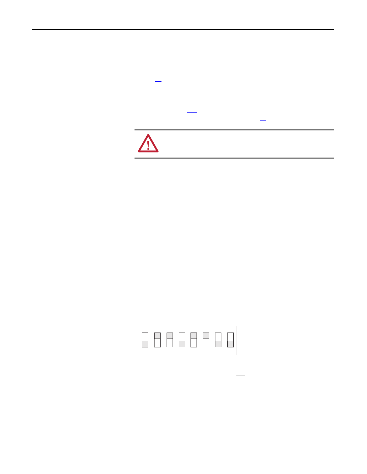
Chapter 1 Installation and Wiring
Note: This illustration is an example configuration
for a drive with a field supply amp rating of 20 A
and a motor with a rated field current less than or
equal to 17 A.
Field Current Configuration
DIP switch S14 on the drive’s control circuit board is factory set to the minimum
field current rating based on the drive size (see DIP Switch and Jumper Settings
on page 75
for S14 location). The configuration of this switch must be changed
to be greater than or equal to the rated field current specified on the motor
nameplate (unless a permanent magnet motor is being used) or possible motor
damage may result. In addition, the value selected with switch S14 must be
entered in parameter 374
drive is commissioned (see Drive Start Up on page 91
[Drv Fld Brdg Cur] in the control software when the
.)
ATTENTION: DIP switch S14 must be set to a value that is greater than or equal
to the rated field current specified on the motor nameplate or possible motor
damage may result.
Set DIP Switch S14 to the Correct Value
Complete the following steps to set switch S14 to the correct field current value.
1. Locate and record the frame size and field supply amp rating listed on the
drive data nameplate (see Drive Nameplate Data on page 12
for location).
2. Locate and record the rated field current value listed on the motor data
nameplate.
3. For frame A, B, and C drives:
• Use Ta b l e 1 6
on page 61 to set switch S14 to be the equivalent or next
higher value as compared to the motor’s rated field current.
For frame D drives:
• Use Ta b l e 1 7
or Ta b l e 1 8 on page 61 to set switch S14 to be the
equivalent or next higher value as compared to motor’s rated field
current.
Figure 36 - Example DIP Switch S14 Configuration
ON
1
3 4
2
5
6
DIP
78
Note : The configuration of switch S14 is not required if the motor’s field control
is provided via an external source (for example, a permanent magnet motor),
however, it is recommended that the switch settings be completed as described
above.
60 Rockwell Automation Publication 20P-UM001K-EN-P - July 2014
Page 61

Installation and Wiring Chapter 1
Table 16 - DIP Switch S14 Field Current Configuration Settings Frames A, B and C Drives
Switch ohms > 168.5 333.3 182 36.4 845 1668 3333 – Equivalent
Field Current Scale S14-1 S14-2 S14-3 S14-4 S14-5 S14-6 S14-7 S14-8 Ohms
1 A OFF OFF OFF OFF OFF ON
2 A OFF OFF OFF OFF ON OFF 845
3 A OFF OFF OFF OFF ON ON 560.9
5 A OFF ON OFF OFF OFF OFF 333.3
10 A ON OFF OFF OFF OFF OFF 168.5
13 A ON OFF OFF OFF ON ON 129.6
17 A OFF ON ON OFF ON ON 97.3
20 A ON OFF ON OFF OFF ON 83.1
Not used
(OFF)
Resistance
1668
Table 17 - DIP Switch S14 Field Current Configuration Settings for Frame D Drives and Standalone
Regulators with a Rated Field Supply of 40 A
Switch ohms > 168.5 333.3 182 36.4 845 1668 3333 – Equivalent
Field Current Scale S14-1 S14-2 S14-3 S14-4 S14-5 S14-6 S14-7 S14-8 Ohm
1 A OFF OFF OFF OFF OFF OFF ON
2 A OFF OFF OFF OFF OFF ON OFF 1668
4 A OFF OFF OFF OFF ON OFF OFF 845
6 A OFF OFF OFF OFF ON ON OFF 560.9
10 A OFF ON OFF OFF OFF OFF OFF 333.3
20 A ON OFF OFF OFF OFF OFF OFF 168.5
30 A ON ON OFF OFF OFF OFF OFF 111.9
40 A ON OFF ON OFF OFF ON OFF 83.1
Resistance
3333
Not
used
(OFF)
Table 18 - DIP Switch S14 Field Current Configuration Settings for Frame D Drives and Standalone
Regulators with a Rated Field Supply of 70 A
Switch ohms > 168.5 333.3 182 36.4 845 1668 3333 – Equivalent
Field Current Scale S14-1 S14-2 S14-3 S14-4 S14-5 S14-6 S14-7 S14-8 Ohm
1 A OFF OFF OFF OFF OFF ON OFF
5 A OFF ON OFF OFF OFF OFF OFF 333.3
10 A ON OFF OFF OFF OFF OFF OFF 168.5
20 A ON OFF ON OFF OFF ON OFF 83.1
50 A OFF ON OFF ON OFF OFF OFF 32.8
70 A ONONONONOFFOFFOFF 23.9
Rockwell Automation Publication 20P-UM001K-EN-P - July 2014 61
Resistance
1668
Not
used
(OFF)
Page 62

Chapter 1 Installation and Wiring
Relay Outputs
Terminals 35 and 36 and 75 and 76 are N.O. relay outputs. The relay output
between terminals 35 and 36 is configured with parameter 1392
[Relay Out 1 Sel]. The relay output between terminals 75 and 76 is configured
with parameter 629
[Relay Out 2 Sel]. See Contactors on page 30 for more
information.
Terminals Description Maximum
Voltag e
35, 36 Normally open contact. Configured with parameter 1392 [Relay Out 1
Sel], set to 25 “Contactor” by default.
250V AC 1 A75, 76 Normally open contact. Configured with parameter 629 [Relay Out 2
Sel], set to 5 “Ready” by default.
78, 79 Motor thermistor (PTC) or thermal switch connections
Maximum
Current
Note: If external contactor coil current ratings are greater than 1 amp, use an
interposing relay between the drive relay 1 or relay 2 output and the contactor
coil.
Thermistors and Thermal Switches
To detect motor overheating and protect the motor from overloading, an
external, user-supplied thermistor (PTC) or thermal switch must be connected
to terminals 78 and 79. The drive’s response to a motor over temperature fault is
configured in parameter 365
switch is not used, a 1 k
79 (installed at the factory). Follow the appropriate instructions below when
installing a thermal sensor.
[OverTemp Flt Cfg]. If a thermistor or thermal
Ω resistor must be connected between terminals 78 and
Thermistors (PTC)
PTC thermistors fitted in the motor can be connected directly to the drive via
terminals 78 and 79. In this case the 1 k
terminals 78 and 79.
Thermal Switches (Klixon®) in the Motor Windings
“Klixon” type temperature-dependent contacts can disconnect the drive from the
motor via an external control or can be configured as an external fault by using a
digital input on drive. They can also be connected to terminals 78 and 79 to
indicate a drive “Motor Over Temp” fault (F16), though this is not
recommended due to the noise sensitivity of the current threshold circuitry. If a
thermal switch is used a 1 k
and one of the terminals.
62 Rockwell Automation Publication 20P-UM001K-EN-P - July 2014
Ω resistor must be placed in series between the switch
Ω resistor is not required between
Page 63

Installation and Wiring Chapter 1
78 79 35 36 75 76
Note: Terminals 78 and 79 shown with 1
kΩ resistor in place of temperature sensor.
78 79 35 36 75 76
Table 19 - Relay Outputs and Thermistor/Thermal Switch Wire Sizes and Specifications
Signal Type Terminals Wire Size and Type
Flexible
(mm2)
Relay Outputs 35 & 36, 75 & 76
Thermistor and
Thermal Switches
(1) See Cable and Wiring Recommendations on page 43 for more information.
78 & 79
0.140…1.500 0.140…1.500 26…14 0.5 (4.4)
(1)
Multi-core
(mm2)
AWG
Tightening
Tor que
N•m (lb•in)
Figure 37 - Frame A Relay and Thermistor/Thermal Switch Terminal Block Locations
Figure 38 - Frame B Relay and Thermistor/Thermal Switch Terminal Block Locations
Rockwell Automation Publication 20P-UM001K-EN-P - July 2014 63
Page 64

Chapter 1 Installation and Wiring
35 36 75 76 78 79
Lower, right side of the control pan.
78 79 35 36 75 76
Figure 39 - 230V/460C AC Input Frame C Relay and Thermistor/Thermal Switch Terminal Block
Locations
Figure 40 - 575V/690C AC Input Frame C Relay and Thermistor/Thermal Switch Terminal Block
Locations
64 Rockwell Automation Publication 20P-UM001K-EN-P - July 2014
Page 65

Installation and Wiring Chapter 1
Control pan, to the left of the
HIM cradle.
78 79 35 36 75 76
Figure 41 - Frame D Relay and Thermistor/Thermal Switch Terminal Block Locations
Control Circuit Input Power
The control circuit must be powered by a clean, external 230V AC or 115V AC
single phase power supply. For frame B and C drives only
between terminals SA and SB for 115V AC control input power. For frame B
drive SA-SB terminal block location, see Figure 47
SA-SB terminal block location, see Figure 47
on page 68.
Note: If the SA-SB terminal block is not configured for the correct input voltage,
“No Fault” (F0) displays on the HIM, if installed.
Terminals Description
U2, V2 Single phase AC power for the control circuits
PE Safety ground (on frame C drive terminal blocks only)
Table 20 - Control Circuit Wire Sizes and Terminal Specifications
Terminals Wire Size and Type
Flexible
2
)
(mm
U2, V2 0.14…1.5 0.14…2.5 26…14 0.5 (4.4)
PE 2.5…10 2.5…10 12…8 2.0 (18.0)
(1) See Cable and Wiring Recommendations on page 43 for more information.
(1)
Multi-core
(mm2)
AWG
Tightening Torque
N•m (lb•in)
, a jumper is required
on page 68. For frame C drive
Rockwell Automation Publication 20P-UM001K-EN-P - July 2014 65
Page 66

Chapter 1 Installation and Wiring
U2 V2
U2 V2
U2 V2 PE
Figure 42 - Frame A Control Circuit Terminal Block Location
Figure 43 - Frame B Control Circuit Terminal Block Location
Figure 44 - 230V/460V AC Input Frame C Control Circuit Terminal Block Location
66 Rockwell Automation Publication 20P-UM001K-EN-P - July 2014
Page 67

Installation and Wiring Chapter 1
Lower, right side of the control pan.
U2 V2
U2 V2
Figure 45 - 575V/690V AC Input Frame C Control Circuit Terminal Block Location
Figure 46 - Frame D Control Circuit Terminal Block Location
Rockwell Automation Publication 20P-UM001K-EN-P - July 2014 67
Page 68
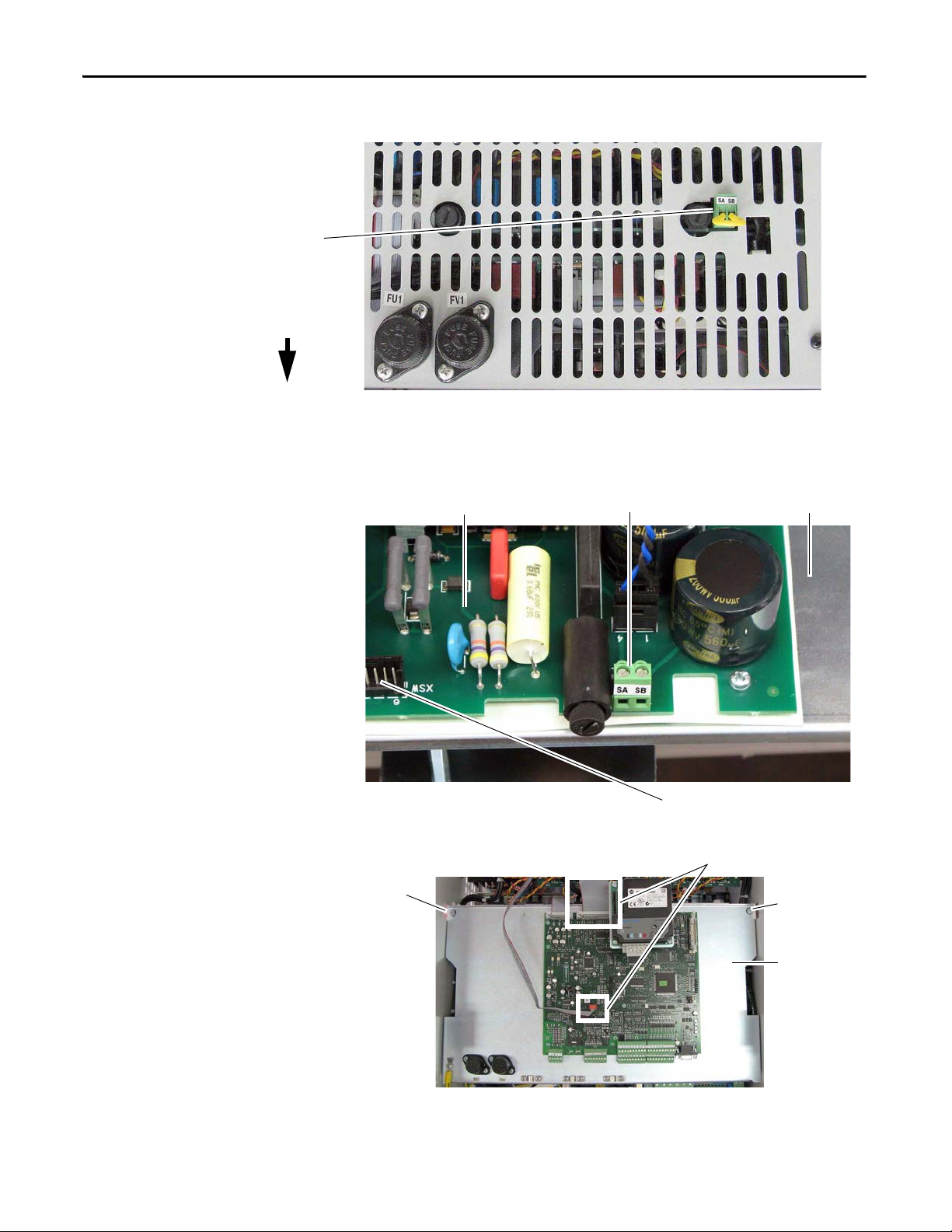
Chapter 1 Installation and Wiring
Front of Drive
Top, right side of drive.
Switching power supply board SA-SB terminals Back of control board EMI shield
The SA-SB terminal block is on the switching power supply
circuit board on the back of the control board EMI shield.
1. Remove the top protective cover from the drive.
3. Loosen
captive
screws.
2. Disconnect cables XFCD and XR.
4. Lower control
board EMI shield
and disconnect
cable XSW from
switching power
supply board (see
above).
XSW connector
To access the SA-SB terminal block:
3. Loosen captive
screws.
Figure 47 - SA-SB Terminal Block Location on Frame B Drives
Figure 48 - SA-SB Terminal Block Location on Frame C Drives
68 Rockwell Automation Publication 20P-UM001K-EN-P - July 2014
Page 69

Installation and Wiring Chapter 1
Frame C Heatsink Cooling Fan Specifications
Frame C drives require an external 230V AC power supply for the heatsink
cooling fans. If sourced from the main 3 phase AC input, the power supply
connections must be taken from the primary side of the installed Isolation
Transformer or Line Reactor (clean power).
In addition, the fan power input terminals U3 and V3 are required to be short
circuit protected. This protection can be provided by using a circuit breaker or
fuses.
• If a circuit breaker is used, it must be rated for the short circuit available
current of the feeder source for this circuit and the inrush current of the
fan. Size the circuit breaker to primarily protect the wiring from the circuit
breaker connections to terminals U3 and V3, and not nuisance trip or
blow from the inrush current.
• If fuses are used, they must be rated for either 230V AC, 2.0 Amps (slow
blow).
Table 21 - Frame C Heatsink Cooling Fans Terminal Designations
Terminal Description Maximum Voltage Maximum Current
U3
V3
Single-phase AC input power for cooling fans. 230V AC 1 A
Table 22 - Frame C Heatsink Cooling Fans Wire Sizes and Terminal Specifications
Terminals Wire Size and Type
Flexible
(mm2)
U3, V3 0.14…1.5 0.14…2.5 26…16 0.4 (3.5)
(1) See Cable and Wiring Recommendations on page 43 for more information.
(1)
Multi-core
(mm2)
AWG
Tightening Torque
N•m (lb•in)
Rockwell Automation Publication 20P-UM001K-EN-P - July 2014 69
Page 70

Chapter 1 Installation and Wiring
U3 V3
Lower, right side of the control pan.
U3 V3
Figure 49 - 230V/460V AC Input Frame C Heatsink Cooling Fan Terminal Block Location
Figure 50 - 575V/690V AC Input Frame C Heatsink Cooling Fan Terminal Block Location
70 Rockwell Automation Publication 20P-UM001K-EN-P - July 2014
Page 71

Installation and Wiring Chapter 1
IMPORTANT
Airflow Direction
Airflow Direction
Frame D, Series B Heatsink Cooling Fan Specifications
The Frame D, series B drive cooling fan requires three phase (50/60 Hz),
400…460V AC input power. If sourced from the main 3 phase AC input, the
power supply connections must be taken from the primary side of the installed
isolation transformer or line reactor (clean power).
When connecting the fan power wiring, verify that the airflow exits through
the top of the drive. If the airflow is incorrect, switch the leads on terminals U3
and V3.
The cooling fan power input terminals U3, V3 and W3 are required to be short
circuit protected. This protection can be provided by using a circuit breaker or
fuses.
• If a circuit breaker is used, it must be rated for the short circuit available
current of the feeder source for this circuit and the inrush current of the
fan. Size the circuit breaker to primarily protect the wiring from the circuit
breaker connections to terminals U3, V3, and W3, and not nuisance trip
or blow from the inrush current.
• If fuses are used, they must be rated for either 400V AC, 2.5 Amps (slow
blow), or 460V AC, 3.15 Amps (slow blow).
A normally closed (N.C.) contact wired to terminals 31 and 32 of the fan
terminal block can be connected to an external device to provide indication of a
fan supply failure or can be wired to drive digital input terminals configured for
14 “Aux Fault” (via Pars 133…144).
Rockwell Automation Publication 20P-UM001K-EN-P - July 2014 71
Page 72

Chapter 1 Installation and Wiring
Top View
of Drive
Series B terminal
block shown
Table 23 - Frame D, Series B Heatsink Cooling Fan Terminal Designations
Terminal Block Terminal Description AC Voltage Max Current
U3 Three-phase AC input
V3
power connections
400…460V AC
(50/60 Hz)
1.5 A
W3
PE Safety ground – –
31 Normally clo sed contact 250V AC 1 A
32
Table 24 - Frame D Heatsink Cooling Fan Signal Wire Sizes and Terminal Specifications
Terminals Wire Size and Type
Flexible (mm2) Multi-core (mm2)AWG
U3, V3, W3, 31, 32, PE 0.14…1.5 0.14…2.5 28…12 0.5…0.6 (4.4…5.3)
(1) See Cable and Wiring Recommendations on page 43 for more information.
(1)
Tightening Torque
N•m (lb•in)
Figure 51 - Frame D Heatsink Cooling Fan Terminal Block Location
U3 V3 W3 PE 31 32
U3 V3 W3 PE 31 32
72 Rockwell Automation Publication 20P-UM001K-EN-P - July 2014
Page 73
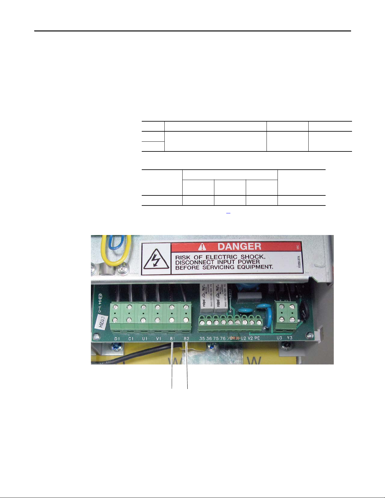
Installation and Wiring Chapter 1
81 82
Frame C and D Armature Fuse Signal Terminals
Terminals 81 and 82 on frame C and D drives are connected to the indicating
switch mounted on each of the internal armature circuit protection fuses. These
terminals can be connected to an external device to provide indication that the
fuses have opened. Alternatively, terminals 81 and 82 can be wired to drive digital
input terminals configured for 64 “Invert Flt” (via Pars 133…144).
Table 25 - Armature Fuse Signal Terminal Designations
Terminal Description Maximum Voltage Maximum Current
81
82
Table 26 - Armature Fuse Signal Wire Size and Terminal Specifications
Terminals Wire Size and Type
81, 82 0.14…1.5 0.14…2.5 26…16 0.4 (3.5)
Internal armature fuse intervention signal. 250V AC 1 A
Flexible
2
(mm
)
(1)
Multi-core
(mm2)
AWG
Tightening Torque
N•m (lb•in)
(1) See Cable and Wiring Recommendations on page 43 for more information.
Figure 52 - 230V/460V AC Input Frame C Internal Armature Fuse Signal Terminal Block Location
Rockwell Automation Publication 20P-UM001K-EN-P - July 2014 73
Page 74

Chapter 1 Installation and Wiring
Lower, right side of the control pan.
81 82
81 82
Figure 53 - 575V/690V AC Input Frame C Internal Armature Fuse Signal Terminal Block Location
Figure 54 - Frame D Internal Armature Fuse Signal Terminal Block Location
74 Rockwell Automation Publication 20P-UM001K-EN-P - July 2014
Page 75

Installation and Wiring Chapter 1
See Tab le 27 on page 76 for
descriptions corresponding to
the ID numbers shown here.
1
6
9
2
3
8
5
4
7
Do not use - for
engineering use only.
DIP Switch and Jumper Settings
DIP switches and jumpers on the control circuit board are used to configure the
drive for flashing firmware to the control board EEPROM, the appropriate speed
feedback device settings, analog input signals and minimum field current.
Figure 55 - Control Circuit Board DIP Switch and Jumper Locations
S15
1 2 3 4 5 6 7 8
1 2 3 4 5 6 7 8
S3
RST
S2
ACT
RUN
S1
PWR
S0
S18
S12
DEBUG
S4
- A B C +
- A B C +
1 2 3 4 5 6 7 8
S21
ENC_5 ENC_12
S14
ON
S20
A+ A- B+ B- Z+ Z- COM +V
A+ A- B+ B- Z+ Z- COM +V
S11
S10
S9
21 22 23 24 25 26 27 28 29 30
21 22 23 24 25 26 27 28 29 30
1 2 3 4 5 6 7 8 9 10
1 2 3 4 5 6 7 8 9 10
ON
31 32 33 34 35 36 37 38 39 40
31 32 33 34 35 36 37 38 39 40
11 12 13 14 15 16 17 18 19 20
11 12 13 14 15 16 17 18 19 20
Rockwell Automation Publication 20P-UM001K-EN-P - July 2014 75
Page 76

Chapter 1 Installation and Wiring
1
2
3
= ON
= OFF
4
5
6
7
8
= ON
= OFF
9
= 12-15V
= 5V
ENC_5 ENC_12
ENC_5 ENC_12
Table 27 - Control Circuit Board Jumper and DIP Switch Settings
ID Jumper/
Function Factory Default Example
Switch
S0 For factory boot flashing only. Leave set to the factory setting. Jumper Off
Jumper On Firmware boot
Jumper Off Normal function
S1 For factory boot flashing only. Leave set to the factory setting. Jumper Off
Jumper On Write firmware boot code
Jumper Off Boot code on flash is protected
S2 Not used. Leave set to the factory setting. Jumper Off
S3 For factory boot flashing only. Leave set to the factory setting. Jumper Off
Jumper On Reset
Jumper Off Normal function
S4 Configures the input voltage of the DC analog tachometer.
See Tab le 2 8
on page 77 for configuration.
90V –
S9 Configures the input signal of Analog Input 1 (terminals 1 and 2): On
Off Position 0…20 mA / 4…20 mA
On Position 0…10V / ±10V
Note: The input signal type must also be programmed accordingly in Par 71 [Anlg In1 Config].
S10 Configures the input signal of Analog Input 2 (terminal 3 and 4): On
Off Position 0…20 mA / 4…20 mA
On Position 0…10V / ±10V
Note: The input signal type must also be programmed accordingly in Par 76 [Anlg In2 Config].
S11 Configures the input signal of Analog Input 3 (terminals 5 and 6): On
Off Position 0…20 mA / 4…20 mA
On Position 0…10V / ±10V
Note: The input signal type must also be programmed accordingly in Par 81 [Anlg In3 Config].
S12 Not used. Leave set to the factory setting. Off –
= ON
= OFF
=OFF
S14 Field current resistors setting, see Field Current Configuration on page 60
.
The value selected with switch S14 must be entered in Par 374 [Drv Fld Brdg Cur] when the drive is
commissioned. For permanent magnet motor applications, leave set to the factory default settings.
S15 Configuration of the control circuit board to the appropriate drive size. Leave set to the factory setting, unless the
control board has been supplied as a spare part. See DIP Switch S15 Settings on page 77
based on drive current rating code.
S18 Not used. Leave set to the factory setting. Off –
S20 Monitoring of the Z channel of the Digital Encoder on connector XE2: On
Off Position Z channel monitored
On Position Z channel not monitored
The S20 setting must match the value selected in Par 652 [Encoder Err Chk].
For example, if S20 = “Off”, then Par 652 = 1 “Enabled”.
S21 Encoder power supply voltage and input selection:
This switch setting determines both the power supply (input) and feedback level (output) voltage of the
connected encoder.
Note: When control power is supplied to the drive, the appropriate LED lights to indicate the selection of the
switch.
ENC_5 +5 V encoder (+2.5…5.4V input range)
ENC_12 +12…15 V encoder (+5.4V…15.2V input range)
76 Rockwell Automation Publication 20P-UM001K-EN-P - July 2014
for switch configuration
Minimum field
current rating based
on drive size.
Armature current
based on drive size.
12…5 V
–
–
Page 77

Installation and Wiring Chapter 1
Note: The illustration depicts the DIP switch
settings for 90V (factory default).
1
ON
2
3 4
5
6
78
DIP
Note: Illustration for example only.
DIP Switch S4 Settings
ATTENTION: The drive can overspeed if DIP switch S4 is set incorrectly or the
tachometer is wired incorrectly. Failure to observe this precaution could result in
damage to, or destruction of, the equipment.
DIP switch S4 must be configured to be greater than or equal to the maximum
DC input voltage. Maximum DC Input Voltage = (Tach Volts/1000 rpm) x Par
45 [Max Ref Speed] x 1.1. See Drive Reference and Feedback Scaling on page
for details on programming speed feedback values.
279
Figure 56 - DC Analog Tachometer DIP Switch S4 Example
ON
1
3 4
2
5
6
DIP
78
Table 28 - DC Analog Tachometer DIP Switch S4 Configuration
Maximum DC
Input Voltage
22V ON ON ON ON
45V ONONONOFF
90V ON ON OFF OFF
180V ON OFF OFF OFF
300V OFF OFF OFF OFF
S4-1
S4-8
S4-2
S4-7
S4-3
S4-6
S4-4
S4-5
DIP Switch S15 Settings
DIP Switch S15 is configured for the appropriate drive size at the factory. Do not
change the settings unless you are installing a replacement control board.
Figure 57 - Drive Size DIP Switch S15 Example
Rockwell Automation Publication 20P-UM001K-EN-P - July 2014 77
Page 78

Chapter 1 Installation and Wiring
Table 29 - Drives with 230V Input - DIP Switch S15 Configuration
Frame Drive Current
A 7P0 ON OFF OFF OFF OFF OFF OFF OFF
B 146 ON ON OFF ON OFF OFF OFF OF F
C 521 ON OFF OFF OFF ON OFF OFF OFF
D
Rating Code
9P0 OFF ON OFF OFF OFF OFF OFF OFF
012 ON ON OFF OFF OFF OFF OFF OFF
020 OFF OFF ON OFF OFF OFF OFF OFF
029 ON OFF ON OFF OFF OFF OFF OF F
038 OFF ON ON OFF OFF OFF OFF OFF
055 ON ON ON OFF OFF OFF OFF OFF
073 OFF OFF OFF ON OFF OFF OFF OFF
093 ON OFF OFF ON OFF OFF OFF OFF
110 OFF ON OFF ON OFF OFF OFF OFF
180 OFF OFF ON ON OFF OFF OFF OFF
218 ON OFF ON ON OFF OFF OFF OFF
265 OFF ON ON ON OFF OFF OFF OFF
360 ON ON ON ON OFF OFF OFF OFF
434 OFF OFF OFF OFF ON OFF OFF OFF
700 OFF ON OFF OFF ON OFF OFF OFF
875 ON ON OFF OFF ON OFF OFF OFF
1K0 OFF OFF ON OFF ON OFF OFF OFF
S15-1 S15-2 S15-3 S15-4 S15-5 S15-6 S15-7 S15-8
Table 30 - Drives with 460V Input - DIP Switch S15 Configuration
Frame Drive Current
A
Rating Code
4P1 OFF OFF OFF OFF OFF OFF ON OFF
6P0 ON OFF OFF OFF OFF OFF ON OFF
010 OFF ON OFF OFF OFF OFF ON OFF
014 ON ON OFF OFF OF F OFF ON OFF
019 OFF OFF ON OFF OFF OFF ON OFF
027 ON OFF ON OFF OFF OFF ON OFF
035 OFF ON ON OFF OFF OFF ON OFF
045 ON ON ON OFF OFF OFF ON OFF
052 OFF OFF OFF ON OFF OFF ON OFF
073 ON OFF OFF ON OFF OFF ON OFF
086 OFF ON OFF ON OFF OFF ON OFF
100 ON ON OFF ON OFF OFF ON OFF
129 OFF OFF ON ON OF F OFF ON OFF
S15-1 S15-2 S15-3 S15-4 S15-5 S15-6 S15-7 S15-8
78 Rockwell Automation Publication 20P-UM001K-EN-P - July 2014
Page 79

Installation and Wiring Chapter 1
Frame Drive Current
B 167 ON OFF ON ON OFF OFF ON OFF
C 495 OFF ON OFF OFF ON OFF ON OFF
D
Rating Code
207 OFF ON ON ON OFF OFF ON OFF
250 ONON ON ONOFFOFFONOFF
330 OFF OFF OFF OFF ON OFF ON OFF
412 ON OFF OFF OFF ON OFF ON OFF
667 ON ON OFF OFF ON OFF ON OFF
830 OFF OFF ON OFF ON OFF ON OFF
996 ON OFF ON OFF ON OFF ON OFF
1K1 OFF ON ON OFF ON OFF ON OFF
1K3 ON ON ON OFF ON OFF ON OFF
1K4 OFF OFF OFF ON ON OFF ON OFF
S15-1 S15-2 S15-3 S15-4 S15-5 S15-6 S15-7 S15-8
Table 31 - Drives with 575V Input - DIP Switch S15 Configuration
Fram
e
Drive Current
Rating Code
B
C 540 ON OFF ON OFF OFF OFF OFF ON
D 810 ON ON ON OFF OFF OFF OFF ON
067 OFF OFF OFF OFF OFF OFF OFF ON
101 ON OFF OFF OFF OFF OFF OFF ON
135 OFF ON OFF OFF OFF OFF OFF ON
270 ON O N OFF OFF OFF OFF OFF ON
405 OFF OFF ON OFF OFF OFF OFF ON
675 OFF ON ON OF F OFF OFF OFF ON
1K0 OFF OFF OFF ON OFF OFF OFF ON
1K2 ON OFF OFF ON OFF OFF OFF ON
1K3 OFF ON OFF ON OFF OFF OFF ON
1K6 ON ON OFF ON OFF OFF OFF ON
S15-1 S15-2 S15-3 S15-4 S15-5 S15-6 S15-7 S15-8
Rockwell Automation Publication 20P-UM001K-EN-P - July 2014 79
Page 80

Chapter 1 Installation and Wiring
IMPORTANT
Table 32 - Drives with 690V Input - DIP Switch S15 Configuration
I/O Wiring
Frame Drive Current
Rating Code
C 452 OFF OFF OFF OFF OFF OFF ON ON
565 ON OFF OFF OFF OFF OFF ON ON
D 678 OFF ON OFF OFF OFF OFF ON ON
791 ON ON OFF OFF OFF OFF ON ON
904 ON OFF ON OFF OFF OFF ON ON
1K0 OFF ON ON OFF OFF OFF ON ON
1K1 ON ON ON OFF OFF OFF ON ON
1K2 OFF OFF OFF ON OFF OFF ON ON
1K4 OFF ON OFF ON OFF OFF ON ON
1K5 ON ON OFF ON OFF OFF ON ON
S15-1 S15-2 S15-3 S15-4 S15-5 S15-6 S15-7 S15-8
Observe the following points when installing I/O wiring:
• Use copper wire only.
• Wire with an insulation rating of 600V or greater is recommended.
I/O terminals labeled “(–)” or “Common” are not referenced to earth ground
and are designed to greatly reduce common mode interference. Grounding
these terminals can cause signal noise.
ATTENTION: Configuring an analog input for current operation and driving it from
a voltage source could cause component damage. Verify proper switch
configuration prior to applying input signals. See DIP Switch and Jumper Settings
on page 75
.
ATTENTION: Hazard of personal injury or equipment damage exists when bipolar
input sources are used. Noise and drift in sensitive input circuits can cause
unpredictable changes in motor speed and direction. Use speed command
parameters to help reduce input source sensitivity.
80 Rockwell Automation Publication 20P-UM001K-EN-P - July 2014
Page 81

Installation and Wiring Chapter 1
Terminal Block 3
Ter mina l Bl ock 1
Ter minal Bloc k 4
Terminal Block 2
2
3
4
5
1
7
8
9
10
6
I/O Signal and Control Wiring
Eight (8) digital inputs, four (4) digital outputs, three (3) analog inputs, and two
(2) analog outputs are available on the standard I/O terminal blocks provided
with the drive. One digital input (1…8) must be configured for “Enable” (digital
input 4 by default = “Enable”). See I/O and Control Wire Routing on page 89
for information on routing I/O signal and control wires.
Additional digital and analog I/O is available when the optional I/O expansion
circuit board is installed. See Appendix F
for more information. Also, you can use
the optional 115V AC Converter circuit board to convert 115V AC digital input
signals to 24V DC digital inputs signals to interface with the digital inputs on the
standard I/O terminal blocks. See Appendix G
Table 33 - Analog I/O, Digital I/O and DC Analog Tachometer Wire Sizes and Terminal
Specifications
Signal Type Terminal Block
(Terminals)
Analog and Digital I/O TB1…4 (1…40)
DC Analog Tach M3 (+ and –)
Wire Size and Type
Flexible (mm
0.140…1.500 0.140…1.500 26…16 0.4 (3.5)
for more information.
(1)
2
)Multi-core
(mm2)
AWG
Tightening
Tor que
N•m (lb•in)
(1) See Cable and Wiring Recommendations on page 43 for more information.
Figure 58 - I/O Terminal Block Locations
Table 34 - I/O Terminal Block 1 Designations
No. Signal Description Factory Default Config. Parameter
1 Analog Input 1 (+) Isolated
2 Analog Input 1 (–)
3 Analog Input 2 (+) 0 “Off” 75 [Anlg In2 Sel]
4 Analog Input 2 (–)
5 Analog Input 3 (+) 0 “Off” 80 [Anlg In3 Sel]
6 Analog Input 3 (–)
7 +10V Pot Reference 2…5 kΩ load. Max ±10V, 10 mA. – –
8 –10V Pot Reference
9 Pot Common For (+) and (–) 10V pot references. – –
10 PE ground PE ground to drive chassis. – –
(1)
, bipolar, differential
±10V / 0…20 mA or 4…20 mA.
Important: 0…20 mA or 4…20 mA operation
requires that switch S9, S10, and S11 on the control
board be in the “Off” position. Drive damage may
occur if the switch is not in the correct position based
on the type of input signal. See Ta bl e 2 7
on page 54.
Max ±10V, Max 0.25 mA.
1 “Speed Ref A” 70 [Anlg In1 Sel]
(1) D ifferential Isolation - External source must be maintained at less than 160V with respect to PE. Input provides high common mode immunity.
Rockwell Automation Publication 20P-UM001K-EN-P - July 2014 81
Page 82

Chapter 1 Installation and Wiring
12
13
14
15
11
17
18
19
20
16
22
23
24
25
21
27
28
29
30
26
32
33
34
35
31
37
38
39
40
36
Table 35 - I/O Terminal Block 2 Designations
No. Signal Description Factory Default Config. Parameter
11 Internal 0V (Gnd) – –
12 Digital Input 1 Max +30V, 15V/3.2 mA, 24V/5 mA,
13 Digital Input 2 3 “Start” 134 [Digital In2 Sel]
14 Digital Input 3 11 “Jog” 135 [Digital In3 Sel]
15 Digital Input 4 1 “Enable” 136 [Digital In4 Sel]
and 30V/6.4 mA.
A digital input (1…8) must be configured for
“Enable”.
16 Digital Input Common Important: When the internal +24V DC supply
2 “Stop/CF” 133 [Digital In1 Sel]
––
(terminal 19) is used for digital inputs 1…4, you
must connect the digital input common (terminal
16) to the +24V supply common (terminal 18).
17 Not Used – –
18 24V Supply Common Common for the internal power supply. – –
19 Internal +24V DC Supply Drive supplied +24V DC I/O power.
––
Max. +20…30V, 200 mA
Note: The total current draw is the sum of encoder
power, digital outputs and any other loads connected
to terminal 19.
20 PE ground PE ground to drive chassis. – –
Table 36 - I/O Terminal Block 3 Designations
No. Signal Description Factory
Default
21 Analog Output 1 (+) Max. ±10V, 5 mA. 12 “Motor Speed” 66 [Anlg Out1 Sel]
22 Analog Output 1 (–)
23 Analog Output 2 (+) 13 “Motor Curr” 67 [Anlg Out2 Sel]
24 Analog Output 2 (–)
25 Digital Output Common – –
26 Digital Output 1 Max. +30V, 50 mA 5 “Ready” 145 [Digital Out1 Sel]
27 Digital Output 2 9 “Fault” 146 [Digital Out2 Sel]
28 Digital Output 3 2 “Spd Thresh” 147 [Digital Out3 Sel]
29 Digital Output 4 4 “CurrentLimit” 148 [Digital Out4 Sel]
30 Digital Output +24V DC Source Tie point for the internal supply or customer
––
supplied voltage for the digital outputs. See the
I/O Wiring Examples for sourcing digital outputs
on page85
for more information.
Max. +30V DC, 80 mA.
Important: When the internal +24V DC supply
(terminal 19) is used for digital outputs 1…4,
you must connect terminal 19 to terminal 30 and
the digital output common (terminal 25) to the
+24V supply common (terminal 18).
Config. Parameter
Table 37 - I/O Terminal Block 4 Designations
No. Signal Description Factory Default Config. Parameter
31 Digital Input 5 Max +30V, 15V/3.2 mA, 24V/5 mA,
32 Digital Input 6 18 “Speed Sel 2” 138 [Digital In6 Sel]
33 Digital Input 7 19 “Speed Sel 3” 139 [Digital In7 Sel]
34 Digital Input 8 31 “Contactor” 140 [Digital In8 Sel]
and 30V/6.4 mA.
A digital input (1…8) must be configured for
“Enable”.
35 Digital Input Common Important: When the internal +24V DC supply
(terminal 19) is used for digital inputs 5…8, you
must connect the digital input common (terminal
35) to the +24V supply common (terminal 18).
36
Not Used – –
…
40
82 Rockwell Automation Publication 20P-UM001K-EN-P - July 2014
17 “Speed Sel 1” 137 [Digital In5 Sel]
––
Page 83
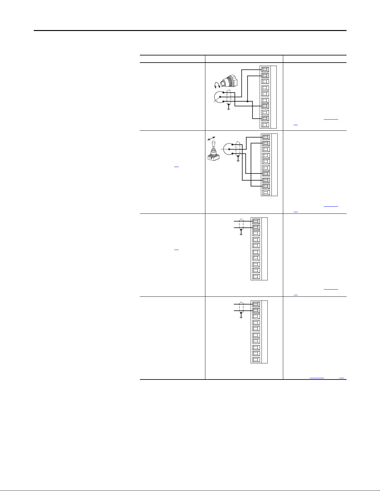
Installation and Wiring Chapter 1
1
2
3
4
5
6
7
8
9
10
I/O Wiring Examples
Input/Output Connection Example Required Parameter Changes
Potentiometer Unipolar Speed
Reference
10kΩ Pot. Recommended
(2kΩ Minimum)
• Adjust Scaling:
1
72 [Anlg In1 Scale] and
2
73 [Anlg1 Tune Scale]
3
• View Signal Value:
4
1404 [Analog In1 Value]
5
6
• Vi ew Sign al Output:
385 [Speed Ref Out]
7
8
Note: Ver ify that DI P switch S9 is set
to “On” (0…10V). See Tab le 27
9
page 54.
10
on
Joystick Bipolar Speed
Reference
±10V Input
Important: See the Attention
statement on page 80
for important
bipolar wiring information.
Analog Input Bipolar Speed
Reference
±10V Input
Important: See the Attention
statement on page 80 for important
bipolar wiring information.
Analog Input Unipolar Speed
Reference
0…+10V Input
or
0…20 mA or 4…20 mA
+
Common
+
Common
• Set Direction Mode:
1322 [Direction Mode]
= 1 “Bipolar”
• Adjust Scaling:
72 [Anlg In1 Scale] and
73 [Anlg1 Tune Scale]
• View Signal Value:
1404 [Analog In1 Value]
• Vi ew Sign al Output:
385 [Speed Ref Out]
Note: Ver ify that DI P switch S9 is set
to “On” (0…10V). See Tab le 27
on
page 54.
1
2
3
4
5
6
7
8
9
10
• Configure for Voltage or Current:
71 [Anlg In1 Config]
• Adjust Scaling:
72 [Anlg In1 Scale] and
73 [Anlg1 Tune Scale]
• View Signal Value:
1404 [Analog In1 Value]
• Vi ew Sign al Output:
385 [Speed Ref Out]
Note: Ver ify that DI P switch S9 is set
to “On” for 0…10V operation, or
“Off” for 0…20 mA or 4…20 mA
operation. See Tab l e 27
on page 54.
Rockwell Automation Publication 20P-UM001K-EN-P - July 2014 83
Page 84

Chapter 1 Installation and Wiring
21
22
23
24
25
26
27
28
29
30
+–
11
12
13
14
15
16
17
18
19
20
11
12
13
14
15
16
17
18
19
20
Stop
Start
Input/Output Connection Example Required Parameter Changes
Analog Output Bipolar Signal
±10V Bipolar (based on the signal of
the assigned input source - for
example Analog Input 1)
• Select Source Value:
66 [Anlg Out1 Sel]
• Adjust Scaling:
62 [Anlg Out1 Scale]
or
0…10V Unipolar (shown)
Enable Input
24V DC internal supply
2-Wire Control Non-Reversing
24V DC internal supply
Important: Programming inputs
for 2-wire control deactivates the
HIM Start and Jog buttons.
2-Wire Control
Reversing
24V DC external supply
Important: Programming inputs
for 2-wire control deactivates the
HIM Start and Jog buttons.
+24V
Stop-Run
Run Fwd.
Run Rev.
Neutral/
Common
• No Changes Required.
Note: If the digital input used for
“Enable” is changed from the
default setting of digital input 4,
the wiring must be changed
accordingly.
• Disable Digital Input 1:
11
12
13
14
15
16
17
18
19
20
11
12
13
14
15
16
17
18
19
20
133 [Digital In1 Sel]
= 0 “Not Used”
• Set Digital Input 2:
134 [Digital In2 Sel]
= 5 “Run”
• Set Digital Input 1:
133 [Digital In1 Sel]
= 6 “Run Forward”
• Set Digital Input 2:
134 [Digital In2 Sel]
= 7 “Run Reverse”
3-Wire Control
24V DC internal supply
84 Rockwell Automation Publication 20P-UM001K-EN-P - July 2014
• No Changes Required.
Page 85
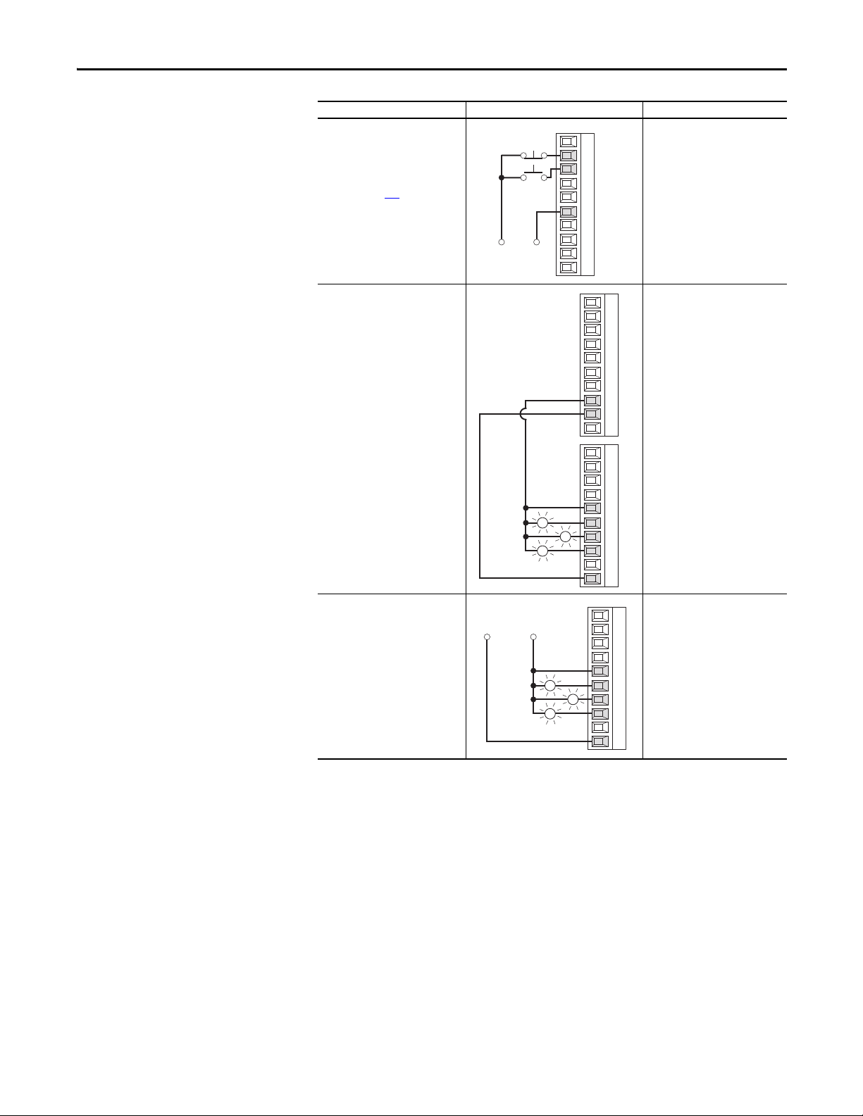
Installation and Wiring Chapter 1
11
12
13
14
15
16
17
18
19
20
Stop
Start
+24V
Neutral/
Common
21
22
23
24
25
26
27
28
29
30
Ready
Fault
External
+24V DC
External
Neutral/
Common
Spd Thresh
Input/Output Connection Example Required Parameter Changes
3-Wire Control
• No Changes Required
24V DC external supply
Requires 3-wire functions only
([Digital In1 Sel]). configuring
2-wire selections will cause a type 2
alarm (see page 224
).
Sourcing Digital O utputs
Internal 24V DC supply
Sourcing Digital O utputs
External 24V DC supply
Ready
Fault
Spd Thresh
• No Changes Required
11
12
13
14
15
16
17
18
19
20
21
22
23
24
25
26
27
28
29
30
• No Changes Required
Rockwell Automation Publication 20P-UM001K-EN-P - July 2014 85
Page 86
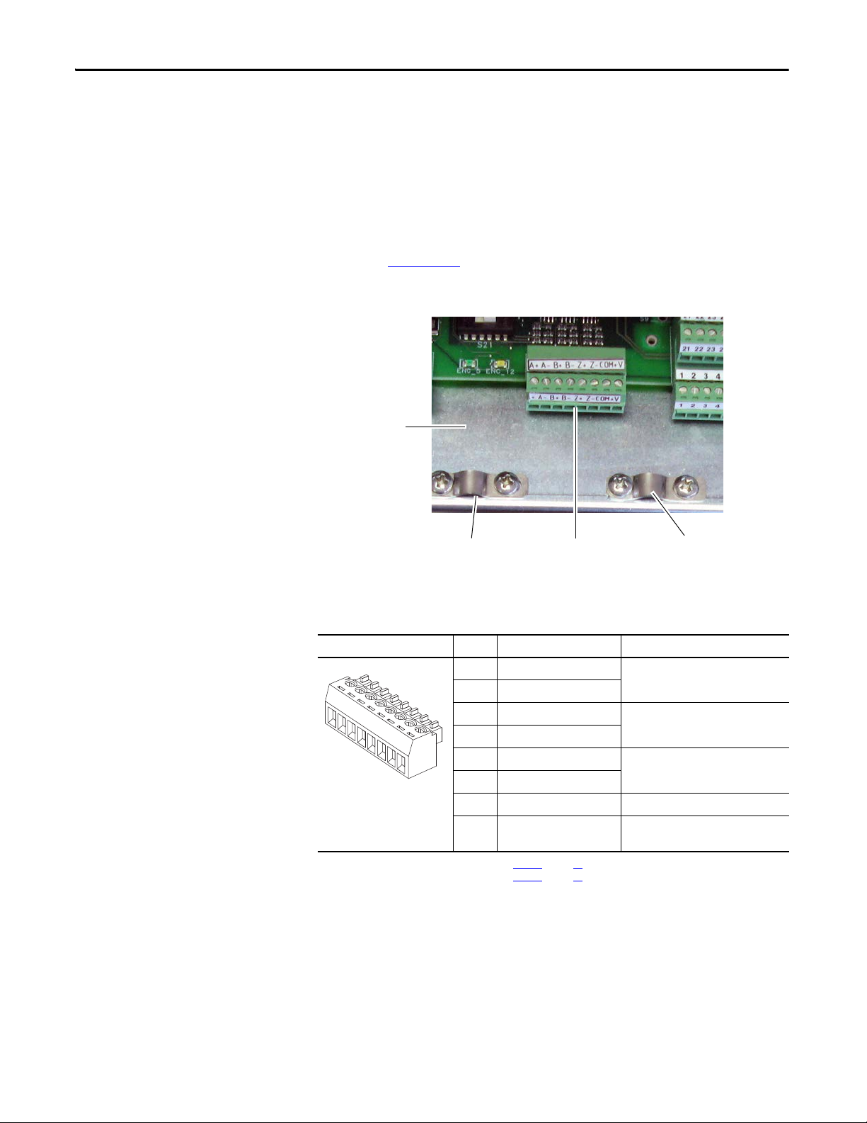
Chapter 1 Installation and Wiring
Digital Encoder terminal block
Control board
EMI shield
Wire s hield g round
Wire s hield g round
Digital Encoder Terminal Block
Always connect the encoder connection cables directly to the terminals on the
encoder terminal block. The encoder cable must be made up of twisted pairs with
the shield connected to the shield ground on the drive side. Do not connect the
shield to ground on the motor side. In some cases (for example, cable lengths that
exceed 100 meters), it may be necessary to ground the shield of each twisted pair
on the power supply. See the PowerFlex Digital DC Drive Technical Data,
publication 20P-TD001
Figure 59 - Digital Encoder Terminal Block Location
, for digital encoder specifications.
Table 38 - Digital Encoder Terminal Designations
Terminal Block Label Signal
A+ Encoder A Single channel A or dual channel
A+
A-
B+
B-
Z+
Z-
COM
+V
(1) S electable via switch S21 on the control board. See Tabl e 2 7 on page 76.
(2) S electable via switch S20 on the control board. See Tabl e 2 7 on page 76.
A- Encoder A (NOT)
B+ Encoder B Single channel B or dual channel
B- Encoder B (NOT)
Z+ Encoder Z Pulse, marker or registration input
Z- Encoder Z (N OT)
(1)
COM +5/12…15V
+V +5/12…15V
DC Return Internal power common
(1)
DC Power
Description
quadrature A input
quadrature B input
(2)
Internal power source
200 mA
86 Rockwell Automation Publication 20P-UM001K-EN-P - July 2014
Page 87

Figure 60 - Sample Encoder Power Wiring
Common
+5/12-15V DC
(200 mA)
A+
A-
B+
B-
Z+
Z-
COM
+V
to Shield
(1)
B
B NOT
A NOT
A
Z
Z NOT
Supply Common
A+
A-
B+
B-
Z+
Z-
COM
+V
to Shield
(1)
Power Source Connection Example
Internal Drive Power
+5/12…15V DC, 200 mA
(1)
Installation and Wiring Chapter 1
External Power Source
+V
COM
Z-
Z+
B-
B+
+
External
Power
Supply
Common
A-
A+
(1) Shield connec tion is on drive control board EMI shield. See Figure 59 on page 86.
Figure 61 - Sample Encoder Signal Wiring
Encoder Signal Connection Example
Single-Ended, Dual Channel
to
Shield
(1)
Differential, Dual Channel
+V
COM
to Shield
Z NOT
Z
B NOT
B
A NOT
A
(1)
Z-
Z+
B-
B+
A-
A+
Rockwell Automation Publication 20P-UM001K-EN-P - July 2014 87
Page 88

Chapter 1 Installation and Wiring
Analog Tachometer
terminal block
A
B
C
+
−
DC Analog Tachometer Terminal Block
Figure 62 - Analog Tachometer Terminal Block Location
See the PowerFlex Digital DC Drive Technical Data, publication 20P-TD001,
for DC analog tachometer specifications.
ATTENTION: The drive can overspeed if DIP switch S4 is set incorrectly, or the
tachometer is wired incorrectly. Failure to observe this precaution could result in
damage to, or destruction of, the equipment.
Table 39 - DC Analog Tachometer Terminal Designations
Label Signal Description
– Negative input –
A
(Not Used)B
C
+ Positive input
See Verify Motor Rotation and Run Feedback
Polarity Checks on page 103
on determining feedback polarity.
(1) Max imum voltage depends on the configuration of DIP switch S4. See DC Analog Tachometer DIP Switch S4 Example on page 77.
for informati on
22.7 / 45.4 / 90.7 / 181.6 / 302.9V
max voltage
8 mA max. current
(1)
Resolver Feedback Module
The resolver feedback module (catalog number 20P-RES-A0), which provides a
drive interface to a selection of compatible resolvers, must be ordered and
purchased separately from the drive. The resolver option module includes the
PowerFlex DC Drive Resolver Feedback Module Installation Instructions,
publication 20P-IN071
Resolver Type Selection on page 310
resolvers.
, which provides installation and wiring information. See
for more information on compatible
88 Rockwell Automation Publication 20P-UM001K-EN-P - July 2014
Page 89

Installation and Wiring Chapter 1
Frame A Shown
I/O and Control Wire Routing
Frames A…C
Route all I/O and control wires from through the bottom of the drive, between
the bottom front protective cover and the terminal cover (frame A) or plastic
covers (frames B and C).
Frame D
Route the field power input cables through the opening at the top left side of the
control panel.
Route control and I/O cables through the opening at the bottom left side of the
control panel.
Rockwell Automation Publication 20P-UM001K-EN-P - July 2014 89
Page 90

Chapter 1 Installation and Wiring
Notes:
90 Rockwell Automation Publication 20P-UM001K-EN-P - July 2014
Page 91

Chapter 2
IMPORTANT
Drive Start Up
This chapter describes how to start up the PowerFlex DC drive. If using the LCD
HIM (Human Interface Module) to commission the drive, it is recommended
that you read Appendix B
ATTENTION: Power must be applied to the drive to perform the following startup procedure. Some of the voltages present are at incoming line potential. To
avoid electric shock hazard or damage to equipment, allow only qualified service
personnel to perform the following procedure. Thoroughly read and understand
the procedure before beginning. If an event does not occur while performing this
procedure, Do Not Proceed. Remove Power including user supplied control
voltages. Correct the malfunction before continuing.
- HIM Overview before performing these procedures.
Drive Start Up Checklist
It is recommended that you uncouple the motor from all loads at this time,
until otherwise directed.
This checklist contains the major steps required to complete the drive
commissioning procedure.
❏ Verify all Drive Configuration Settings - page 92
❏ Verify the Power Wiring - page 92
❏ Verify the Control and I/O Wiring - page 92
❏ Apply Voltage to the Control Circuits - page 93
❏ Verify the Control Voltages - page 95
❏ Load the Default Settings - page 95
❏ Configure the Most Commonly Used Parameters - page 95
❏ Tun e th e Cur ren t R eg ul at or - page 101
❏ Verify Motor Rotation and Run Feedback Polarity Checks - page 103
❏ Configure the Speed Feedback Parameters - page 106
❏ Tune the Speed Regulator - page 108
.
.
.
.
.
.
.
.
.
.
.
❏ Verify Speed Reference Settings and Drive Operation - page 110
Rockwell Automation Publication 20P-UM001K-EN-P - July 2014 91
.
Page 92

Chapter 2 Drive Start Up
Before Applying Power to the Drive
Verify all Drive Configuration Settings
1. With the bottom cover removed from the drive (see Remove the Drive
Covers on page 27
the rated field current specified on the motor nameplate. See Ta b l e 1 6
on page 61
2. Verify all switch settings (S9, S10, and S11) for the analog inputs. See
Ta b l e 2 7
3. Verify all DIP switch and jumper settings for the digital encoder or
analog tachometer feedback device. See Ta b l e 2 7
Figure 56
.
on page 76.
on page 77.
ATTENTION: The Drive can overspeed if DIP switch S4 is set incorrectly, or the
tachometer is wired incorrectly. Failure to observe this precaution could result in
damage to, or destruction of, the equipment.
), verify that DIP switch S14 is set correctly to be ≥
on page 76 and
Verify the Power Wiring
• Verify that the AC line power at the disconnect device is within the rated
value of the drive and that all power wiring is correct. See Power Wiring on
page 44
for further information.
ATTENTION: Do not connect any external power to the armature output
terminals, personal injury and/or equipment damage can occur.
Verify the Control and I/O Wiring
1. Verify that control power and I/O wiring is correct. A digital input (1…8
only) must be wired and configured as a drive enable. See Control
Circuit Input Power on page 65
information.
2. If you are using a PTC thermistor or thermal switch to protect the
motor from overloading, remove the 1 k
and 79. See Thermistors and Thermal Switches on page 62
and I/O Wiring on page 80 for further
Ω resistor between terminals 78
92 Rockwell Automation Publication 20P-UM001K-EN-P - July 2014
Page 93

Drive Start Up Chapter 2
IMPORTANT
Applying Power to the Drive
The remainder of the “Drive Start Up” procedure in this manual uses a HIM to
configure and autotune the drive. If you prefer, you can use the DriveExplorer™,
DriveTools™ SP, or Connected Components Workbench™ software to program
drive parameters or use the drive “Start Up” wizard (basic application
configuration only) available with both software packages. You must use
DriveExplorer v5.02 or higher or DriveTools SP v4.01 or higher with a PowerFlex
DC drive specific software patch. The patch can be downloaded from http://
www.ab.com/support/abdrives/webupdate/.
If an operator interface is not available, use a remote device to start up the drive.
For information on using the HIM, see the HIM Overview on page 265
When power is first applied, the HIM may require approximately 5 seconds
until commands are recognized (including the Stop key).
.
Apply Voltage to the Control Circuits
1. Apply power to the control circuits (terminals U2 and V2) of the drive.
2. If any of the digital inputs are configured to “Stop/CF” (CF = Clear
Fault), “Enable” or “Aux Fault,” verify that signals are present or
reconfigure [Digital Inx Sel]. If a fault code displays, see Chapter 4 Troubleshooting on page 215
.
3. If the STS LED is not flashing green at this point, see “Drive Status
Indicators” below.
Rockwell Automation Publication 20P-UM001K-EN-P - July 2014 93
Page 94

Chapter 2 Drive Start Up
2
1
Figure 63 - Drive Status Indicators
PORT
MOD
NET A
NET B
STS
# Name Color State Description
1 STS
(Status)
Green Flashing Drive ready, but not running and no faults are present.
Steady Drive running, no faults are present.
Yellow Flashing, Drive
Stopped
Flashing, Drive
Running
A condition exists that is preventing the drive from starting. Check
parameters 1403 [Start Inhibits] and/or 1380 [Drive Alarm 1].
An intermittent type 1 alarm condition is occurring. Check parameter
1380 [Drive Alarm 1]. See Fault Descriptions on page 218
and/or Alarm
Descriptions on page 224.
Steady,
Drive Running
A continuous type 1 alarm condition exists. Check parameter 1380 [Drive
Alarm 1]. See Fault Descriptions on page 218
and/or Alarm Descriptions
on page 224.
Red Flashing A fault has occurred. Check [Fault x Code] or view the Fault Queue on the
HIM. See Fault Descriptions on page 218
.
Steady A non-resettable, non-configurable fault has occurred. Check [Fault x
Code] or view the Fault Queue on the HIM. See Fault Descriptions on page
218
.
2 PORT Refer to the Communication
MOD Status of communications module (when installed).
Adapter User Manu al.
Status of DPI port internal communications (if present).
NET A Status of network (if connected).
NET B Status of secondary network (if connected).
94 Rockwell Automation Publication 20P-UM001K-EN-P - July 2014
Page 95

Drive Start Up Chapter 2
IMPORTANT
Verify the Control Voltages
• Verify that the following voltages are present at I/O terminal block 1 and
2. See I/O Signal and Control Wiring on page 81
Terminal Number… Voltage to Terminal Number…
7 +10V 9
8-10V 9
19 +24 - 30V 18
:
Load the Default Settings
It is recommended that you reset the drive to the default settings. By resetting the
drive to the default settings, any previous parameter modifications you have made
will be overwritten.
1. On the HIM, from the “Main” menu scroll to the “Memory Storage”
menu.
2. Press Enter.
3. Scroll to “Reset To Defaults” and press Enter.\
A message displays to verify that you want to reset the drive to the
factory settings.
4. Press Enter.
Note: A “Params Defaulted” (F48) entry will be made in the drive’s Fault
Queue to indicate the change.
Configure the Most Commonly Used Parameters
If your application only requires basic drive parameter set up, you can use the
S.M.A.R.T. list screen available on the HIM to program the drive. See Using the
S.M.A.R.T. List Screen on page 267
To access all parameters in this procedure you must set the Parameter View
option to “Advanced”.
for more information.
Rockwell Automation Publication 20P-UM001K-EN-P - July 2014 95
Page 96

Chapter 2 Drive Start Up
1. At the Main menu, scroll to the Parameter option.
2. Press ALT and then Sel.
3. Scroll to the Numbered List option.
4. Press Enter.
5. Type 211.
6. Press Enter.
7. Press Sel.
8. Typ e 1 .
9. Press Enter.
10. Press Esc.
11. Press ALT and then Sel.
12. Scroll to the File-Group-Par option.
13. Press Enter.
14. Scroll to the “Motor Control” file.
15. Press Enter.
96 Rockwell Automation Publication 20P-UM001K-EN-P - July 2014
Page 97

Drive Start Up Chapter 2
16. With the “Motor Data” group selected, press Enter.
17. Configure the following parameters:
Note: Parameters 45 [Max Ref Speed] and 162 [Max Feedback Spd] are
typically set to the motor nameplate base speed. However, if a speed
feedback device is used (encoder or tachometer), see Drive Reference
and Feedback Scaling on page 279
for details on setting these
parameters.
❏ 45 [Max Ref Speed] - Enter the motor nameplate base speed.
❏ 162 [Max Feedback Spd] - Enter the motor nameplate base speed.
❏ 175 [Rated Motor Volt] - Enter the rated motor nameplate
armature voltage. This value is the measured armature voltage when
the motor is running at base speed with rated field current and
represents 100% of the rated armature voltage when field weakening
is not used. If field weakening is used, set this value to 90% of the
rated armature voltage to prevent a possible overvoltage condition
when the drive transitions to the field weakening mode.
❏ 179 [Nom Mtr Arm Amps] - Enter the rated motor nameplate
armature current. Note: To prevent current scaling/resolution
issues, the drive size (as set by DIP switch S15 and shown in Par 465
[Drive Size]) can not exceed the motor size (as set by Par 179) by
more than three times.
❏ 374 [Drv Fld Brdg Cur] - Enter the rated current of the field bridge
regulator to match the value set using the DIP switch S14. See Field
Current Configuration on page 60
.
❏ 280 [Nom Mtr Fld Amps] - Enter the rated motor nameplate field
current. If using a permanent magnet motor, leave this parameter set
to the default value.
Rockwell Automation Publication 20P-UM001K-EN-P - July 2014 97
Page 98

Chapter 2 Drive Start Up
IMPORTANT
18. Access the “Field Config” group.
19. Configure the following parameters:
❏ If the motor field power is supplied by an external source, set Par
497 [Field Reg Enable] = 0 “Disabled”. Otherwise, verify that this
parameter is set to 1 “Enabled” (default). Leave set to the default
value if using a permanent magnet motor.
❏ If you are utilizing field economy when the drive is stopped or at
zero speed, set Par 1407 [Field Econ Delay] to the desired amount
of time to elapse after the drive stops or reaches zero speed before
field economy becomes active (the value set in Par 468 [Min Fld
Curr Pct]). The default value is 300 seconds. Leave set to the default
value if using a permanent magnet motor.
❏ Par 469 [Field Mode Sel] - select the desired field mode (default = 0
“Base Speed”, constant field current):
• 1 “Field Weaken”, field weakening mode
• 2 “External”, power to the field is supplied externally
• 3 “PM External”, external field is created by a permanent magnet
(PM) motor
❏ If you are utilizing field economy at zero speed, set 468 [Min Fld
Curr Pct] to the desired minimum field current for field economy
(default = 30%). Leave set to the default value if using a permanent
magnet motor.
❏ If you are operating the drive in field weakening mode, set Par 456
[Fld Weaken Ratio] = Motor nameplate base speed / Par 45 [Max
Ref Speed] x 100. Leave set to the default value if using a permanent
magnet motor.
When operating the drive in field weakening mode, it is necessary to refer to
the CEMF value or to the crossover data. If the maximum field current is not
within 10% of the maximum value of the internal field converter, configure the
current feedback using DIP switch S14. See Field Current Configuration on page
60
.
98 Rockwell Automation Publication 20P-UM001K-EN-P - July 2014
Page 99

Drive Start Up Chapter 2
20. Access the “Utility” file.
21. Press Enter.
22. Access the “Alarms” group.
23. Configure the following parameters:
❏ Par 481 [UnderVolt Thresh] - Enter the value at which an AC under
voltage condition will be detected by the drive (default = 200V on a
240V AC line and 400V on a 480V AC line). Typically, this value is
approximately 85% of the nominal AC line voltage.
❏ Par 584 [OverCurrent Thr] - Enter the value at which a drive over
current condition will be detected (default = 175%). Set the
threshold level at least 10% above the selected operating current
limit (Par 7 [Current Limit]).
❏ Par 585 [OverSpeed Val] - Enter a value that is 10% above the
maximum speed that the motor will achieve. Typically 10% above
Par 162 [Max Feedback Spd].
24. Access the “Input & Output” file.
25. Press Enter.
26. Access the “Analog Inputs” group.
27. Configure the following:
❏ If you have connected a potentiometer to analog input 1 for a speed
reference:
• Verify that Par 70 [Anlg In1 Sel] is set to 1 “Speed Ref A”
(default).
• Verify that switch S9 and Par 71 [Anlg In1 Config] are
configured to match (voltage versus a current signal). See DIP
Switch and Jumper Settings on page 75
.
• Set Par 72 [Anlg In1 Scale] and Par 74 [Anlg In1 Offset]
appropriately.
❏ If you are using the HIM on the drive cover (Port 1) for the speed
reference, set Par 70 [Anlg In1 Sel] to 0 “Off ”.
Rockwell Automation Publication 20P-UM001K-EN-P - July 2014 99
Page 100

Chapter 2 Drive Start Up
28. Access the “Digital Inputs” group.
29. Configure the following parameters:
❏ Par 1391 [ContactorControl] - Select the type of contactor(s) used
with the drive: 1 “Contactor” (default, AC input or DC output
contactor), 2 “Contactor+DB” (AC input or DC output contactor
and dynamic brake contactor), or 0 “None”.
Note : If you select 0 “None” for Par 1391 [ContactorControl], a
“CntactrCflct” alarm will display. The alarm will be resolved and
automatically clear when you complete the Digital Output
configuration below.
Note : If Par 1391 [ContactorControl] is set to 1 or 2, an Auxiliary
Status contactor must be wired to a digital input (default for digital
input 8).
❏ Par 140 [Digital In8 Sel] - If a contactor is NOT used, set to other
than 31 “Contactor” (for example, 0 “Not Used”).
❏ If an auxiliary status contactor is wired to a digital input, set the
appropriate [Digital Inx Sel] parameter to 31 “Contactor”.
30. Access the “Digital Outputs” group.
31. Configure the following parameters:
❏ If a contactor and a dynamic brake resistor are used:
• Par 629 [Relay Out 2 Sel] = 24 “ContactorDB”.
❏ If a neither a contactor nor a dynamic brake resistor are used:
• Par 629 [Relay Out 2 Sel] = Set to other than 24 “ContactorDB”
or 25 “Contactor” (for example, 0 “Not Used”).
• Par 1392 [Relay Out 1 Sel] = Set to other than 24
“ContactorDB” or 25 “Contactor” (for example, 0 “Not Used”).
100 Rockwell Automation Publication 20P-UM001K-EN-P - July 2014
 Loading...