


User Manual
PowerFlex Digital DC Drive
PowerFlex DC Drive V1.006…5.006, PowerFlex DC Standalone Regulator V1.006…5.006
Important User Information
IMPORTANT
Solid-state equipment has operational characteristics differing from those of electromechanical equipment. Safety
Guidelines for the Application, Installation and Maintenance of Solid State Controls (publication SGI-1.1
your local Rockwell Automation® sales office or online at http://www.rockwellautomation.com/literature/
important differences between solid-state equipment and hard-wired electromechanical devices. Because of this difference,
and also because of the wide variety of uses for solid-state equipment, all persons responsible for applying this equipment
must satisfy themselves that each intended application of this equipment is acceptable.
In no event will Rockwell Automation, Inc. be responsible or liable for indirect or consequential damages resulting from the
use or application of this equipment.
The examples and diagrams in this manual are included solely for illustrative purposes. Because of the many variables and
requirements associated with any particular installation, Rockwell Automation, Inc. cannot assume responsibility or
liability for actual use based on the examples and diagrams.
No patent liability is assumed by Rockwell Automation, Inc. with respect to use of information, circuits, equipment, or
software described in this manual.
Reproduction of the contents of this manual, in whole or in part, without written permission of Rockwell Automation,
Inc., is prohibited.
Throughout this manual, when necessary, we use notes to make you aware of safety considerations.
available from
) describes some
WARNING: Identifies information about practices or circumstances that can cause an explosion in a hazardous environment,
which may lead to personal injury or death, property damage, or economic loss.
ATTENTION: Identifies information about practices or circumstances that can lead to personal injury or death, property
damage, or economic loss. Attentions help you identify a hazard, avoid a hazard, and recognize the consequence.
SHOCK HAZARD: Labels may be on or inside the equipment, for example, a drive or motor, to alert people that dangerous
voltage may be present.
BURN HAZARD: Labels may be on or inside the equipment, for example, a drive or motor, to alert people that surfaces may
reach dangerous temperatures.
Identifies information that is critical for successful application and understanding of the product.
Allen-Bradley, Connected Components Workbench, DriveExplorer, DriveTools SP, PowerFlex, Rockwell Automation, and TechConnect are trademarks of Rockwell Automation, Inc.
Trademarks not belonging to Rockwell Automation are property of their respective companies.

This manual contains new and updated information.
Summary of Changes
New and Updated Information
This table contains the changes made to this revision.
Top ic Pa ge
Added a note to Figure 5
terminal sizes apply to which frame D drive ratings.
Added instructions for drive installations in an ungrounded or high-impedance neutral ground or
systems
Updated the Typical Power Wiring Diagrams and the Field Conver ter Connections section to include
the step-down transformer required in the field converter input power supply circuit for 575V and
690V AC input drives.
Updated the Field Converter Connections section to include information on a requirements for a
step down transformer.
Updated the description for Par 469 [Field Mode Sel] option 1 “Field Weaken” to include the
requirement to wire the armature voltage feedback terminals A1 and A2 on the drive to terminals
A1 and A2 on the motor, respectively, when Par 458 [SpdReg FB Bypass] is set to 1 “Enabled.”
Updated the maximum value listed for parameters 7 [Current Limit], 8 [Current Lim Pos], and 9
[Current Lim Neg] from 200% to 250%.
Added a note to Par 458 [SpdReg FB Bypass] requiring, that when set to 1 “Enabled” and Par 469
[Field Mode Sel] is set 1 “Field Weaken,” the armature voltage feedback terminals A1 and A2 on the
drive must be wired to terminals A1 and A2 on the motor, respec tively.
Updated the S-curve parameter descriptions (19, 665, 666, 667, and 668) to better reflect the
function of the ramp time.
Updated the drive armature overcurrent trip specifications. 212
Added the noise level values for each drive frame fan. 215
Updated the Bussmann North American Fuse Block part numbers for frame A and B drives. 219
Added the new S-curve Configuration section. 284
Updated the Ramp Reference Block Diagram to reflect the interaction of the linear and S-curve
ramps.
- Frame D Dimensions - Right Side and Front Views indicating which
Figure 5
35
46 and 56
56
126
127
133
144 and 146
319
Changes to this manual for previous revisions are included in Appendix I History
of Changes on page 351
Rockwell Automation Publication 20P-UM001I-EN-P - February 2013 3
.

Summary of Changes
Notes:
4 Rockwell Automation Publication 20P-UM001I-EN-P - February 2013

Table of Contents
Preface
Installation and Wiring
Drive Storage Conditions. . . . . . . . . . . . . . . . . . . . . . . . . . . . . . . . . . . . . . . . . 11
Drive Nameplate Data. . . . . . . . . . . . . . . . . . . . . . . . . . . . . . . . . . . . . . . . . . . . 12
Drive Frame Sizes . . . . . . . . . . . . . . . . . . . . . . . . . . . . . . . . . . . . . . . . . . . . . . . . 12
Drive Firmware Version . . . . . . . . . . . . . . . . . . . . . . . . . . . . . . . . . . . . . . . . . . 12
Specifications . . . . . . . . . . . . . . . . . . . . . . . . . . . . . . . . . . . . . . . . . . . . . . . . . . . . 12
Additional Resources . . . . . . . . . . . . . . . . . . . . . . . . . . . . . . . . . . . . . . . . . . . . . 13
Technical Support . . . . . . . . . . . . . . . . . . . . . . . . . . . . . . . . . . . . . . . . . . . . . . . 13
Conventions. . . . . . . . . . . . . . . . . . . . . . . . . . . . . . . . . . . . . . . . . . . . . . . . . . . . . 13
General Precautions . . . . . . . . . . . . . . . . . . . . . . . . . . . . . . . . . . . . . . . . . . . . . . 14
Standard Drive Catalog Number Explanation . . . . . . . . . . . . . . . . . . . . . . 15
Standard Drive Catalog Number Explanation, Cont.. . . . . . . . . . . . . . . . 16
Standalone Regulator Catalog Numbers. . . . . . . . . . . . . . . . . . . . . . . . . . . . 16
Chapter 1
Mounting Considerations . . . . . . . . . . . . . . . . . . . . . . . . . . . . . . . . . . . . . . . . 18
Operating Conditions and Temperatures. . . . . . . . . . . . . . . . . . . . . . . 18
Minimum Mounting Clearances. . . . . . . . . . . . . . . . . . . . . . . . . . . . . . . 18
Approximate Drive Dimensions and Weights . . . . . . . . . . . . . . . . . . . . . . 19
Lifting PowerFlex DC Drives . . . . . . . . . . . . . . . . . . . . . . . . . . . . . . . . . . . . . 25
Mounting Frame C and D Drives. . . . . . . . . . . . . . . . . . . . . . . . . . . . . . 25
Removing the Drive Covers . . . . . . . . . . . . . . . . . . . . . . . . . . . . . . . . . . . . . . . 28
Frame A Drives . . . . . . . . . . . . . . . . . . . . . . . . . . . . . . . . . . . . . . . . . . . . . . 28
Frame B and C Drives . . . . . . . . . . . . . . . . . . . . . . . . . . . . . . . . . . . . . . . . 29
Frame D . . . . . . . . . . . . . . . . . . . . . . . . . . . . . . . . . . . . . . . . . . . . . . . . . . . . . 30
Isolation Transformers / Line Reactors . . . . . . . . . . . . . . . . . . . . . . . . . . . . 30
Using Contactors . . . . . . . . . . . . . . . . . . . . . . . . . . . . . . . . . . . . . . . . . . . . . . . . 31
AC Input Contactors. . . . . . . . . . . . . . . . . . . . . . . . . . . . . . . . . . . . . . . . . 32
DC Output Contactors. . . . . . . . . . . . . . . . . . . . . . . . . . . . . . . . . . . . . . . 32
Dynamic Brake Resistors. . . . . . . . . . . . . . . . . . . . . . . . . . . . . . . . . . . . . . 32
General Grounding Requirements. . . . . . . . . . . . . . . . . . . . . . . . . . . . . . . . . 33
Safety Ground (PE). . . . . . . . . . . . . . . . . . . . . . . . . . . . . . . . . . . . . . . . . . . 34
Power Feeder . . . . . . . . . . . . . . . . . . . . . . . . . . . . . . . . . . . . . . . . . . . . . . . . 34
Encoder/Resolver Ground Connections. . . . . . . . . . . . . . . . . . . . . . . . 34
Tachometer Ground Connections . . . . . . . . . . . . . . . . . . . . . . . . . . . . . 34
Grounding for Installations in an Ungrounded or High-Impedance
Neutral Ground or System . . . . . . . . . . . . . . . . . . . . . . . . . . . . . . . . . . . . . . . . 35
Power Distribution . . . . . . . . . . . . . . . . . . . . . . . . . . . . . . . . . . . . . . . . . . . 35
CE Conformity . . . . . . . . . . . . . . . . . . . . . . . . . . . . . . . . . . . . . . . . . . . . . . . . . . 40
Low Voltage Directive (2006/95/EC). . . . . . . . . . . . . . . . . . . . . . . . . . 40
EMC Directive (2004/108/EC) . . . . . . . . . . . . . . . . . . . . . . . . . . . . . . . 40
General Considerations . . . . . . . . . . . . . . . . . . . . . . . . . . . . . . . . . . . . . . . 40
Installation Requirements Related to the Low Voltage Directive. . 41
Installation Requirements Related to EN 61800-3 and the EMC
Directive . . . . . . . . . . . . . . . . . . . . . . . . . . . . . . . . . . . . . . . . . . . . . . . . . . . . 41
Pollution Degree Ratings According to EN 61800-5-1 . . . . . . . . . . 42
Rockwell Automation Publication 20P-UM001I-EN-P - February 2013 5

Table of Contents
Power Circuit Protection . . . . . . . . . . . . . . . . . . . . . . . . . . . . . . . . . . . . . . . . . 43
Control Power Protection. . . . . . . . . . . . . . . . . . . . . . . . . . . . . . . . . . . . . . . . . 43
Cable and Wiring Recommendations . . . . . . . . . . . . . . . . . . . . . . . . . . . . . . 44
Power Wiring . . . . . . . . . . . . . . . . . . . . . . . . . . . . . . . . . . . . . . . . . . . . . . . . . . . . 45
AC Input Voltages. . . . . . . . . . . . . . . . . . . . . . . . . . . . . . . . . . . . . . . . . . . . 45
DC Output Voltages. . . . . . . . . . . . . . . . . . . . . . . . . . . . . . . . . . . . . . . . . . 46
Typical Power Wiring Diagrams . . . . . . . . . . . . . . . . . . . . . . . . . . . . . . . 46
Armature Converter Connections . . . . . . . . . . . . . . . . . . . . . . . . . . . . . 50
Armature Voltage Feedback Connections. . . . . . . . . . . . . . . . . . . . . . . 53
Field Converter Connections . . . . . . . . . . . . . . . . . . . . . . . . . . . . . . . . . . 56
Field Current Configuration . . . . . . . . . . . . . . . . . . . . . . . . . . . . . . . . . . 60
Set DIP Switch S14 to the Correct Value . . . . . . . . . . . . . . . . . . . . . . . 60
Relay Outputs . . . . . . . . . . . . . . . . . . . . . . . . . . . . . . . . . . . . . . . . . . . . . . . . 62
Thermistors and Thermal Switches . . . . . . . . . . . . . . . . . . . . . . . . . . . . 62
Control Circuit Input Power . . . . . . . . . . . . . . . . . . . . . . . . . . . . . . . . . . 65
Frame C Heatsink Cooling Fans Power Supply Terminals . . . . . . . 68
Frame D Heatsink Cooling Fan Power Supply Terminals . . . . . . . . 69
Frame C and D Armature Fuse Signal Terminals . . . . . . . . . . . . . . . . 70
DIP Switch and Jumper Settings. . . . . . . . . . . . . . . . . . . . . . . . . . . . . . . . . . . 72
I/O Wiring . . . . . . . . . . . . . . . . . . . . . . . . . . . . . . . . . . . . . . . . . . . . . . . . . . . . . . 77
I/O Signal and Control Wiring . . . . . . . . . . . . . . . . . . . . . . . . . . . . . . . . 78
I/O Wiring Examples . . . . . . . . . . . . . . . . . . . . . . . . . . . . . . . . . . . . . . . . 80
Digital Encoder Terminal Block . . . . . . . . . . . . . . . . . . . . . . . . . . . . . . . 83
DC Analog Tachometer Terminal Block . . . . . . . . . . . . . . . . . . . . . . . 85
Resolver Feedback Module . . . . . . . . . . . . . . . . . . . . . . . . . . . . . . . . . . . . 85
I/O and Control Wire Routing . . . . . . . . . . . . . . . . . . . . . . . . . . . . . . . . 86
Drive Start Up
Chapter 2
Drive Start Up Checklist. . . . . . . . . . . . . . . . . . . . . . . . . . . . . . . . . . . . . . . . . . 87
Before Applying Power to the Drive. . . . . . . . . . . . . . . . . . . . . . . . . . . . . . . . 88
Verify all Drive Configuration Settings . . . . . . . . . . . . . . . . . . . . . . . . . 88
Verify the Power Wiring . . . . . . . . . . . . . . . . . . . . . . . . . . . . . . . . . . . . . . 88
Verify the Control and I/O Wiring . . . . . . . . . . . . . . . . . . . . . . . . . . . . 88
Applying Power to the Drive . . . . . . . . . . . . . . . . . . . . . . . . . . . . . . . . . . . . . . 89
Apply Voltage to the Control Circuits. . . . . . . . . . . . . . . . . . . . . . . . . . 89
Verify the Control Voltages . . . . . . . . . . . . . . . . . . . . . . . . . . . . . . . . . . . 91
Load the Default Settings. . . . . . . . . . . . . . . . . . . . . . . . . . . . . . . . . . . . . . 91
Configure the Most Commonly Used Parameters . . . . . . . . . . . . . . . 91
Tune the Current Regulator . . . . . . . . . . . . . . . . . . . . . . . . . . . . . . . . . . . 97
Verify Motor Rotation and Run Feedback Polarity Checks. . . . . . . 99
Configure the Speed Feedback Parameters . . . . . . . . . . . . . . . . . . . . . 102
Tune the Speed Regulator . . . . . . . . . . . . . . . . . . . . . . . . . . . . . . . . . . . . 104
Verify Speed Reference Settings and Drive Operation. . . . . . . . . . . 106
6 Rockwell Automation Publication 20P-UM001I-EN-P - February 2013

Chapter 3
Table of Contents
Programming and Parameters
Troubleshooting
About Parameters . . . . . . . . . . . . . . . . . . . . . . . . . . . . . . . . . . . . . . . . . . . . . . . 109
Parameters Table Example . . . . . . . . . . . . . . . . . . . . . . . . . . . . . . . . . . . 110
How Parameters are Organized. . . . . . . . . . . . . . . . . . . . . . . . . . . . . . . . . . . 111
File–Group–Parameter Order. . . . . . . . . . . . . . . . . . . . . . . . . . . . . . . . 111
Numbered List View. . . . . . . . . . . . . . . . . . . . . . . . . . . . . . . . . . . . . . . . . 111
Cross Reference Tables . . . . . . . . . . . . . . . . . . . . . . . . . . . . . . . . . . . . . . 111
Basic Parameter View . . . . . . . . . . . . . . . . . . . . . . . . . . . . . . . . . . . . . . . . 112
Advanced Parameter View . . . . . . . . . . . . . . . . . . . . . . . . . . . . . . . . . . . 114
Monitor File . . . . . . . . . . . . . . . . . . . . . . . . . . . . . . . . . . . . . . . . . . . . . . . . 119
Motor Control File . . . . . . . . . . . . . . . . . . . . . . . . . . . . . . . . . . . . . . . . . 123
Speed Command File . . . . . . . . . . . . . . . . . . . . . . . . . . . . . . . . . . . . . . . 138
Dynamic Control File . . . . . . . . . . . . . . . . . . . . . . . . . . . . . . . . . . . . . . . 144
Applications File . . . . . . . . . . . . . . . . . . . . . . . . . . . . . . . . . . . . . . . . . . . . 150
Utility File . . . . . . . . . . . . . . . . . . . . . . . . . . . . . . . . . . . . . . . . . . . . . . . . . 163
Communications File . . . . . . . . . . . . . . . . . . . . . . . . . . . . . . . . . . . . . . . 175
Input / Output File . . . . . . . . . . . . . . . . . . . . . . . . . . . . . . . . . . . . . . . . . 179
Parameter Cross Reference – by Name . . . . . . . . . . . . . . . . . . . . . . . . . . . . 190
Parameter Cross Reference – by Number. . . . . . . . . . . . . . . . . . . . . . . . . . 194
Chapter 4
Faults and Alarms . . . . . . . . . . . . . . . . . . . . . . . . . . . . . . . . . . . . . . . . . . . . . . . 199
Drive Status . . . . . . . . . . . . . . . . . . . . . . . . . . . . . . . . . . . . . . . . . . . . . . . . . . . . 200
HIM Indicators . . . . . . . . . . . . . . . . . . . . . . . . . . . . . . . . . . . . . . . . . . . . . 201
Manually Clearing Faults . . . . . . . . . . . . . . . . . . . . . . . . . . . . . . . . . . . . . . . . 201
Fault Descriptions. . . . . . . . . . . . . . . . . . . . . . . . . . . . . . . . . . . . . . . . . . . . . . . 202
Clearing Alarms. . . . . . . . . . . . . . . . . . . . . . . . . . . . . . . . . . . . . . . . . . . . . . . . . 206
Alarm Descriptions . . . . . . . . . . . . . . . . . . . . . . . . . . . . . . . . . . . . . . . . . . . . . 206
Common Drive Symptoms and Corrective Actions . . . . . . . . . . . . . . . . 208
Drive will not start . . . . . . . . . . . . . . . . . . . . . . . . . . . . . . . . . . . . . . . . . . 208
Drive starts but motor does not turn and no armature current . . 209
The motor does not reach commanded speed . . . . . . . . . . . . . . . . . . 209
The motor is turning in the wrong direction . . . . . . . . . . . . . . . . . . 209
The motor reaches maximum speed immediately . . . . . . . . . . . . . . 210
Testpoint Codes and Functions . . . . . . . . . . . . . . . . . . . . . . . . . . . . . . . . . . 210
Supplemental Drive Information
Appendix A
Specifications . . . . . . . . . . . . . . . . . . . . . . . . . . . . . . . . . . . . . . . . . . . . . . . . . . . 212
IP20 NEMA/UL Type Open Watts Loss . . . . . . . . . . . . . . . . . . . . . . . . . 215
Communication Configurations . . . . . . . . . . . . . . . . . . . . . . . . . . . . . . . . . 217
Typical Programmable Controller Configurations . . . . . . . . . . . . . 217
Logic Command/Status Words . . . . . . . . . . . . . . . . . . . . . . . . . . . . . . 217
Drive Power Circuit Protection . . . . . . . . . . . . . . . . . . . . . . . . . . . . . . . . . . 219
Frame A and B Fuse Information . . . . . . . . . . . . . . . . . . . . . . . . . . . . . 219
Frame C and D Fuse Information. . . . . . . . . . . . . . . . . . . . . . . . . . . . . 225
Rockwell Automation Publication 20P-UM001I-EN-P - February 2013 7

Table of Contents
HIM Overview
Control Power Circuit Protection Fuses. . . . . . . . . . . . . . . . . . . . . . . . . . . 233
Switching Power Supply Circuit Board Fuses . . . . . . . . . . . . . . . . . . 233
Frame B Pulse Transformer Circuit Board Fuses . . . . . . . . . . . . . . . 235
Frame C Transient Noise Filter Circuit Board Fuses. . . . . . . . . . . . 236
Frame D Overvoltage Clipping Circuit Board Fuses . . . . . . . . . . . . 237
AC Input Line Reactors and AC Input Contactors. . . . . . . . . . . . . . . . . 238
Isolation Transformers. . . . . . . . . . . . . . . . . . . . . . . . . . . . . . . . . . . . . . . . . . . 241
Dynamic Brake Resistor Kits and DC Output Contactors . . . . . . . . . . 243
DC Contactor Crimp Lug Kit Specifications . . . . . . . . . . . . . . . . . . . . . . 244
Alternate Dynamic Brake Resistor Kits and DC Output Contactors. 245
Alternate EMC Filters . . . . . . . . . . . . . . . . . . . . . . . . . . . . . . . . . . . . . . . . . . . 247
Terminal Adapter Kits for Frame D Drives . . . . . . . . . . . . . . . . . . . . . . . . 250
Appendix B
External and Internal Connections . . . . . . . . . . . . . . . . . . . . . . . . . . . . . . . 251
LCD Display Elements . . . . . . . . . . . . . . . . . . . . . . . . . . . . . . . . . . . . . . . . . . 252
ALT Functions. . . . . . . . . . . . . . . . . . . . . . . . . . . . . . . . . . . . . . . . . . . . . . . . . . 252
Using the S.M.A.R.T. List Screen . . . . . . . . . . . . . . . . . . . . . . . . . . . . . 253
Menu Structure . . . . . . . . . . . . . . . . . . . . . . . . . . . . . . . . . . . . . . . . . . . . . . . . . 254
Viewing and Editing Parameters . . . . . . . . . . . . . . . . . . . . . . . . . . . . . . . . . . 256
LCD HIM . . . . . . . . . . . . . . . . . . . . . . . . . . . . . . . . . . . . . . . . . . . . . . . . . 256
Removing/Installing the HIM. . . . . . . . . . . . . . . . . . . . . . . . . . . . . . . . . . . . 257
Application Notes
Appendix C
Alpha Test Mode. . . . . . . . . . . . . . . . . . . . . . . . . . . . . . . . . . . . . . . . . . . . . . . . 259
Alpha Test Setup and Operation . . . . . . . . . . . . . . . . . . . . . . . . . . . . . 260
Analog Input Configuration . . . . . . . . . . . . . . . . . . . . . . . . . . . . . . . . . . . . . 262
Example 1: . . . . . . . . . . . . . . . . . . . . . . . . . . . . . . . . . . . . . . . . . . . . . . . . . . 262
Example 2: . . . . . . . . . . . . . . . . . . . . . . . . . . . . . . . . . . . . . . . . . . . . . . . . . . 262
Analog Input Signal Comparison . . . . . . . . . . . . . . . . . . . . . . . . . . . . . 263
Current / Speed Curve. . . . . . . . . . . . . . . . . . . . . . . . . . . . . . . . . . . . . . . . . . . 264
Drive Reference and Feedback Scaling. . . . . . . . . . . . . . . . . . . . . . . . . . . . . 265
Armature Voltage Feedback . . . . . . . . . . . . . . . . . . . . . . . . . . . . . . . . . . 266
DC Analog Tachometer Feedback . . . . . . . . . . . . . . . . . . . . . . . . . . . . 266
Encoder Feedback . . . . . . . . . . . . . . . . . . . . . . . . . . . . . . . . . . . . . . . . . . . 266
Drive Reference and Feedback Scaling Examples . . . . . . . . . . . . . . . 266
Speed Feedback. . . . . . . . . . . . . . . . . . . . . . . . . . . . . . . . . . . . . . . . . . . . . . 269
Droop Compensation . . . . . . . . . . . . . . . . . . . . . . . . . . . . . . . . . . . . . . . . . . . 271
Field Weakening Mode Configuration (v1.006) . . . . . . . . . . . . . . . . . . . 271
Using a DC Contactor Only (Firmware v1.006 Only) . . . . . . . . . . 272
Using a DC Contactor and a Dynamic Brake (Firmware v1.006
Only). . . . . . . . . . . . . . . . . . . . . . . . . . . . . . . . . . . . . . . . . . . . . . . . . . . . . . . 272
Using an Inverting Fault Device Only (Firmware v1.006
Only). . . . . . . . . . . . . . . . . . . . . . . . . . . . . . . . . . . . . . . . . . . . . . . . . . . . . . . 272
Using a DC Contactor and an Inverting Fault Device (Firmware
v1.006 Only) . . . . . . . . . . . . . . . . . . . . . . . . . . . . . . . . . . . . . . . . . . . . . . . . 273
8 Rockwell Automation Publication 20P-UM001I-EN-P - February 2013

Table of Contents
Using a DC Contactor, a Dynamic Brake and an Inverting Fault
Device (Firmware v1.006 Only) . . . . . . . . . . . . . . . . . . . . . . . . . . . . . . 274
PID Function. . . . . . . . . . . . . . . . . . . . . . . . . . . . . . . . . . . . . . . . . . . . . . . . . . . 275
Configure a Line Speed Signal . . . . . . . . . . . . . . . . . . . . . . . . . . . . . . . . 276
Configure the Feedback Signal in the Follower Drive(s) . . . . . . . . 277
Configure the Tension Set Point Signal in the Follower
Drive(s) . . . . . . . . . . . . . . . . . . . . . . . . . . . . . . . . . . . . . . . . . . . . . . . . . . . . 279
Reference Control . . . . . . . . . . . . . . . . . . . . . . . . . . . . . . . . . . . . . . . . . . . . . . 280
“Auto” Speed Sources. . . . . . . . . . . . . . . . . . . . . . . . . . . . . . . . . . . . . . . . 280
“Manual” Speed Sources . . . . . . . . . . . . . . . . . . . . . . . . . . . . . . . . . . . . . 280
Changing Speed Sources . . . . . . . . . . . . . . . . . . . . . . . . . . . . . . . . . . . . . 280
Torque Reference Source . . . . . . . . . . . . . . . . . . . . . . . . . . . . . . . . . . . . 280
Auto/Manual Examples. . . . . . . . . . . . . . . . . . . . . . . . . . . . . . . . . . . . . . 281
Resolver Cable Balance Tuning Test . . . . . . . . . . . . . . . . . . . . . . . . . . . . . . 282
Performing the Cable Balance Tuning Test . . . . . . . . . . . . . . . . . . . . 282
Resolver Type Selection . . . . . . . . . . . . . . . . . . . . . . . . . . . . . . . . . . . . . . . . . 283
S-curve Configuration . . . . . . . . . . . . . . . . . . . . . . . . . . . . . . . . . . . . . . . . . . . 284
S-curve Acceleration Ramp Example: . . . . . . . . . . . . . . . . . . . . . . . . . 285
Scale Blocks. . . . . . . . . . . . . . . . . . . . . . . . . . . . . . . . . . . . . . . . . . . . . . . . . . . . . 286
Linking Parameters Via the Scale Block Parameters. . . . . . . . . . . . . 287
Speed Regulation Functions. . . . . . . . . . . . . . . . . . . . . . . . . . . . . . . . . . . . . . 287
Adaptive Speed Regulator . . . . . . . . . . . . . . . . . . . . . . . . . . . . . . . . . . . . 287
Speed Up Function . . . . . . . . . . . . . . . . . . . . . . . . . . . . . . . . . . . . . . . . . . 290
Speed Threshold Indicators . . . . . . . . . . . . . . . . . . . . . . . . . . . . . . . . . . 291
Speed Zero Function . . . . . . . . . . . . . . . . . . . . . . . . . . . . . . . . . . . . . . . . 292
Speed Draw Function. . . . . . . . . . . . . . . . . . . . . . . . . . . . . . . . . . . . . . . . 293
Speed / Torque Mode Selection . . . . . . . . . . . . . . . . . . . . . . . . . . . . . . . . . . 294
Zero Torque Mode . . . . . . . . . . . . . . . . . . . . . . . . . . . . . . . . . . . . . . . . . . 294
Speed Regulation Mode. . . . . . . . . . . . . . . . . . . . . . . . . . . . . . . . . . . . . . 295
Torque Regulation Mode . . . . . . . . . . . . . . . . . . . . . . . . . . . . . . . . . . . . 295
Speed Limited Adjustable Torque (SLAT) Min Mode and
SLAT Max Mode . . . . . . . . . . . . . . . . . . . . . . . . . . . . . . . . . . . . . . . . . . . 295
Sum Mode . . . . . . . . . . . . . . . . . . . . . . . . . . . . . . . . . . . . . . . . . . . . . . . . . . 299
Start At Powerup . . . . . . . . . . . . . . . . . . . . . . . . . . . . . . . . . . . . . . . . . . . . . . . 300
Fine Tuning the Regulators . . . . . . . . . . . . . . . . . . . . . . . . . . . . . . . . . . . . . . 301
Manually Adjusting the Current Regulator Tune Settings . . . . . . 302
Fine Tuning the Field Current Regulator. . . . . . . . . . . . . . . . . . . . . .
304
Fine Tuning the Speed Regulator . . . . . . . . . . . . . . . . . . . . . . . . . . . . . 307
Fine Tuning the Voltage Regulator in the Field Converter . . . . . . 309
Tuning the Field Current Curve. . . . . . . . . . . . . . . . . . . . . . . . . . . . . . 311
Control Block Diagrams
Appendix D
Diagram Conventions . . . . . . . . . . . . . . . . . . . . . . . . . . . . . . . . . . . . . . . 313
Rockwell Automation Publication 20P-UM001I-EN-P - February 2013 9

Table of Contents
Appendix E
Installing a Communication Adapter
Optional Analog and Digital I/O
Expansion Circuit Board
Optional 115V AC to 24V DC I/O
Converter Circuit Board
PowerFlex DC Standalone Regulator
Installation
Communication Adapter Kits. . . . . . . . . . . . . . . . . . . . . . . . . . . . . . . . . . . . 337
What The Communication Adapter Kit Includes . . . . . . . . . . . . . . . . . . 337
Tools That You Need. . . . . . . . . . . . . . . . . . . . . . . . . . . . . . . . . . . . . . . . . . . . 337
Safety Precautions . . . . . . . . . . . . . . . . . . . . . . . . . . . . . . . . . . . . . . . . . . . . . . . 338
Installing the Communication Adapter Module in the Drive. . . . . . . . 338
Frame A:. . . . . . . . . . . . . . . . . . . . . . . . . . . . . . . . . . . . . . . . . . . . . . . . . . . . 339
Frames B and C . . . . . . . . . . . . . . . . . . . . . . . . . . . . . . . . . . . . . . . . . . . . . 340
Frame D . . . . . . . . . . . . . . . . . . . . . . . . . . . . . . . . . . . . . . . . . . . . . . . . . . . . 341
Appendix F
What This Option Board Provides. . . . . . . . . . . . . . . . . . . . . . . . . . . . . . . . 343
I/O Expansion Board Wiring. . . . . . . . . . . . . . . . . . . . . . . . . . . . . . . . . . . . . 343
Appendix G
What This Option Board Provides. . . . . . . . . . . . . . . . . . . . . . . . . . . . . . . . 345
I/O Converter Board Wiring. . . . . . . . . . . . . . . . . . . . . . . . . . . . . . . . . . . . . 346
Appendix H
Installation and Wiring Instructions . . . . . . . . . . . . . . . . . . . . . . . . . . . . . . 349
Appendix I
History of Changes
Index
20P-UM001H-EN-P, April 2011. . . . . . . . . . . . . . . . . . . . . . . . . . . . . . . . . 351
20P-UM001G-EN-P, October 2010 . . . . . . . . . . . . . . . . . . . . . . . . . . . . . . 352
20P-UM001F-EN-P, June 2009 . . . . . . . . . . . . . . . . . . . . . . . . . . . . . . . . . . 353
20P-UM001E-EN-P, November 2008 . . . . . . . . . . . . . . . . . . . . . . . . . . . . 353
10 Rockwell Automation Publication 20P-UM001I-EN-P - February 2013

Preface
Top ic Pa ge
Drive Storage Conditions Below
Drive Nameplate Data 12
Additional Resources 13
Drive Frame Sizes 12
Convent ions 13
General Precautions 14
Standard Drive Catalog Number Explanation 15
Standalone Regulator Catalog Numbers 16
The purpose of this manual is to provide you with the basic information needed
to install, start-up and troubleshoot the PowerFlex DC drive. This manual is
intended for qualified personnel. You must be able to program and operate DC
drives. In addition, you must have an understanding of the parameter settings and
functions detailed in this manual.
Drive Storage Conditions
If it is necessary to store the drive for any length of time before installation, follow
these storage guidelines in order to ensure satisfactory operation at start up and to
maintain warranty coverage:
• After receipt and inspection, repack the drive in its original shipping
container and store in a clean, dry place.
• Place where the ambient temperatures do not exceed -25° C (-13° F) or
+55°C (131° F)
• Place where the relative air humidity range does not exceed 5…95%.
• At an altitude of less than 3,000 meters (10,000 ft.) above sea level.
Rockwell Automation Publication 20P-UM001I-EN-P - February 2013 11

Preface
Note: Certification
Marks Location.
See the data
nameplate label on
your drive for actual
agency certifications.
Drive frame size
Drive serial number
Drive Nameplate Data
Drive Frame Sizes
The PowerFlex DC drive contains a data nameplate label located on the side of
each drive that identifies the specific model number design, applicable AC input
power and DC output power data. All communication with Rockwell
Automation personnel concerning this product should include this information.
Cat No.
20P41AD4P1RA0NNN
UL Type OPEN/IP20
Input: 460VAC 50/60 Hz 3.3A 3 Phase
Output: 500VDC 4.1A REGEN 2.0HP
1 Min Overload Amps
3 Sec Overload Amps
DC Field:
Input: 460VAC 50/60 Hz 10A max. 1 Phase
Output: 360VDC 10A max.
Regulator Power: 115/230VAC 50/60 Hz 1.0/0.5A 1 Phase
MFD. in 2XXX on MMM DD
Made in Italy
6.2
8.2
EXAMPLE ONLY
Series: A
I/O: 24VDC (Standard)
Original Firmware V. 1.001
N223
Frame: A
Serial Number: A23E0042
C
Ind. Cont.
Eq. 31KF
Listed
R
US
Similar PowerFlex DC drive sizes are grouped into frame sizes to simplify spare
parts ordering, dimensioning, etc. The drive frame size can be located just above
the serial number on the data nameplate label. See the Standard Drive Catalog
Number Explanation on page 15
for a list of drive catalog numbers and their
respective frame sizes.
Drive Firmware Version
Specifications
The original firmware version of the drive as shipped from the factory appears on
the data nameplate label just above the certifications. If the firmware version has
been upgraded since the drive was shipped, you can view the current version on
the HIM (if installed). See Diagnostics Menu on page 255
for details.
For drive specification information, see the PowerFlex Digital DC Drive,
Technical Data, 20P-TD001
.
12 Rockwell Automation Publication 20P-UM001I-EN-P - February 2013

Preface
Additional Resources
Technical Support
These documents contain additional information concerning related products
from Rockwell Automation.
Resource Description
Preventive Maintenance of Industrial Control and Drive
System Equipment, DRIVES-TD001
Safety Guidelines for the Application, Installation and
Maintenance of Solid State Control, SGI-1.1
A Global Reference Guide for Reading Schematic Diagrams,
100-2.10
Guarding Against Electrostatic Damage, 8000-4.5.2 Provides common practices to help guard against ESD.
Industrial Automation Wiring and Grounding Guidelines,
publication 1770-4.1
Product Certifications website, http://ab.com
Provides a checklist for performing preventive
maintenance.
Provides general guidelines for the application,
installation, and maintenance of solid-state control in the
form of individual devices or packaged assemblies
incorporating solid-state components.
Provides a simple cross-reference of common schematic/
wiring diagram symbols used throughout various parts of
the world.
Provides general guidelines for installing a Rockwell
Automation industrial system.
Provides declarations of conformity, certificates, and other
certification details.
You can view or download publications at: http://
literature.rockwellautomation.com. To order paper copies of technical
documentation, contact your local Allen-Bradley distributor or Rockwell
Automation sales representative.
For Allen-Bradley Drives Technical Support:
Title Online at . . .
Allen-Bradley Drives Technical Support www.ab.com/support/abdrives
Conventions
• To help differentiate parameter names and LCD display text from other
text, the following conventions will be used:
– Parameter Names will appear in [brackets].
For example: [Armature Voltage].
– Display Text will appear in “quotes.” For example: “Enabled.”
• The following words are used throughout the manual to describe an
action:
Word Mean ing
Can Possible, able to do something
Cannot Not possible, not able to do something
May Permitted, allowed
Must Unavoidable, you must do this
Shall Required and necessary
Should Recommended
Should Not Not recommended
Rockwell Automation Publication 20P-UM001I-EN-P - February 2013 13
Preface
General Precautions
AT TE NT IO N: This drive contains ESD (Electrostatic Discharge) sensitive parts and
assemblies. Static control precautions are required when installing, testing,
servicing or repairing this assembly. Component damage may result if ESD
control procedures are not followed. If you are not familiar with static control
procedures, reference A-B publication 8000-4.5.2, “Guarding Against
Electrostatic Damage” or any other applicable ESD protection handbook.
AT TE NT IO N: An incorrectly applied or installed drive can result in component
damage or a reduction in product life. Wiring or application errors, such as,
undersizing the motor, incorrect or inadequate AC supply, or excessive
surrounding air temperatures may result in malfunction of the system.
AT TE NT IO N: Only qualified personnel familiar with DC drives and associated
machinery should plan or implement the installation, start-up and subsequent
maintenance of the system. Failure to comply may result in personal injury and/
or equipment damage.
AT TE NT IO N: An incorrectly applied or installed bypass system can result in
component damage or reduction in product life. The most common causes are:
• Wiring AC line to drive output or control terminals.
• Improper bypass or output circuits not approved by Allen-Bradley.
• Output circuits which do not connect directly to the motor.
Contact Allen-Bradley for assistance with application or wiring.
14 Rockwell Automation Publication 20P-UM001I-EN-P - February 2013
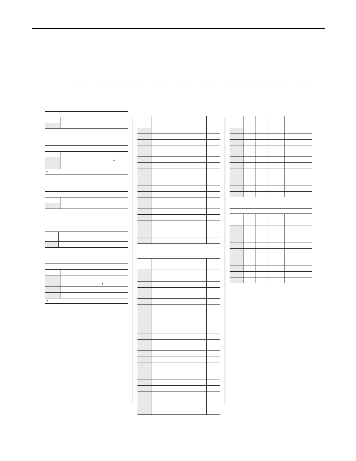
Standard Drive Catalog
Position
1-3 4 5 6 7 8-10 11 12 13 14 15 16
20P 4 1 A D 4P1 R A 0 N N N
abcdef gh i jkl
a
Drive
Code Type
20P PowerFlex DC
b
Motor Operation
Code Type
2 Two Quadrant Operation
4 Four Quadrant Operation
c
Input Type
Code Type
1 6 Pulse
d
Enclosure
Code Enclosure Rating
Conform.
Coat
A IP20, NEMA/UL Type Open
e
Input Voltage
Code Voltage
B 230V AC
D 460V AC
E 600V AC
F 690V AC
f1
f2
Yes
Not available for 230V AC input drives.
Use this code for 400V AC input applications.
f3
f4
2
3
5
7.5
10
15
20
25
30
40
50
60
75
100
125
150
200
250
300
400
500
600
700
800
900
1.5
2.2
3.7
5.5
7.5
11
15
18.5
22
30
37
45
56
75
93
112
149
187
224
298
373
447
552
597
671
4.1
6
10
14
19
27
35
45
52
73
86
100
129
167
207
250
330
412
495
667
830
996
1162
1238
1494
A
A
A
A
A
A
A
A
A
A
A
A
A
B
B
B
B
B
C
C
D
D
D
D
D
10
10
10
10
10
10
10
10
10
14
14
14
14
20
20
20
20
20
20
20
40
40
70
70
70
Hp
Armature
Amps
Frame
Field
Amps
Code kW
460V, 60 Hz Input
4P1
6P0
010
014
019
027
035
045
052
073
086
100
129
167
207
250
330
412
495
667
830
996
1K1
1K3
1K4
1.5
2
3
5
7.5
10
15
20
25
30
40
50
60
75
100
125
150
200
250
300
1.2
1.5
2.2
3.7
5.5
7.5
11
15
18.5
22
30
37
45
56
75
93
112
149
186
224
7
9
12
20
29
38
55
73
93
110
146
180
218
265
360
434
521
700
875
1050
A
A
A
A
A
A
A
A
A
A
B
B
B
B
B
B
C
C
D
D
10
10
10
10
10
10
10
14
14
14
20
20
20
20
20
20
20
20
40
40
Hp
Armature
Amps
Frame
Field
Amps
Code kW
230V, 60 Hz Input
7P0
9P0
012
020
029
038
055
073
093
110
146
180
218
265
360
434
521
700
875
1K0
50
75
100
200
300
400
500
600
800
900
1000
1250
37
56
75
149
224
298
373
447
597
671
746
932
67.5
101.3
135
270
405
540
675
810
1080
1215
1350
1668
B
B
B
B
B
C
C
D
D
D
D
D
20
20
20
20
20
20
20
40
40
40
40
40
Hp
Armature
Amps
Frame
Field
Amps
Code kW
575V, 60 Hz Input
067
101
135
270
405
540
675
810
1K0
1K2
1K3
1K6
298
373
447
552
597
671
746
820
932
1044
Hp
Armature
Amps
Frame
Field
Amps
Code kW
690V, 60 Hz Input
452
565
678
791
904
1K0
1K1
1K2
1K4
1K5
400
500
600
700
800
900
1000
1100
1250
1400
452
565
678
791
904
1017
1130
1243
1413
1582
C
C
D
D
D
D
D
D
D
D
20
20
40
40
40
40
70
70
70
70
Number Explanation
Preface
Rockwell Automation Publication 20P-UM001I-EN-P - February 2013 15

Preface
Position
1-3 4 5 6 7 8-10 11 12 13 14 15 16
20P 4 1 A D 4P1 R A 0 N N N
abcdefgh i jkl
g
Field Supply
Code Type
R Single-Phase Regulated
h
Packaging/Documentation
Code Shipping Carton User Manual
A Yes Yes
i
HIM
Code Operator Interface
0 Blank Cover
Standard - for user installed options, see
Human Interface and Wireless Interface
Modules on page 9.
j
I/O Options
Code Control
N
None (8 - 24V DC Digital Inputs,
4 Digital Outputs, 3 Analog Inputs,
and 2 Analog Outputs are Standard)
k
Communication Options
Code Description
N None
l
Cabinet Options
Code Type
N None
Standard - for user installed options, see
Communication Option Kits on page 10.
All I/O Options are purchased separately and
are user installed. See I/O Options on page 9.
Standard Drive Catalog Number Explanation, Cont.
Standalone Regulator Catalog Numbers
All catalog numbers below are provided with conformally coated circuit boards.
230V / 460V AC Input Regulators 575V / 690V AC Input Regulators Field Amps
Catalog Number Catalog Number
23PMD4 23PMF4 40
23PMD7 23PMF7 70
(1)
23PAMP
(1) Gate Amplifier - used with all voltage classes of the Standalone Regulator. Note: The Standalone Regulator and Gate Amplifier are
currently sold through Rockwell Automation Drive Systems only. Consult the factory for availability.
23PAMP
(1)
(1)
16 Rockwell Automation Publication 20P-UM001I-EN-P - February 2013

Chapter 1
IMPORTANT
IMPORTANT
Installation and Wiring
Topic Page Topic Page
Mounting Considerations 18 CE Conformity 40
Approximate Drive Dimensions and
Wei ght s
Lifting PowerFlex DC Drives 25 Control Power Protection 43
Removing the Drive Covers 28 Cable and Wiring Recommendations 44
Isolation Transformers / Line Reactors 30 Power Wiring 45
Using Contactors 31 DIP Switch and Jumper Settings 72
General Grounding Requirements 33 I/O Wiring 77
19 Power Circuit Protection 43
This chapter provides information on mounting and wiring the PowerFlex DC
drive.
Most start-up difficulties are the result of incorrect wiring. Every precaution must
be taken to assure that the wiring is done as instructed. All items must be read and
understood before the actual installation begins.
For PowerFlex DC Standalone Regulator (SAR) installations, see Appendix H
for important installation and configuration information. The SAR is identified
by a 23PMDx catalog number contained on the data nameplate on the drive (see
Drive Nameplate Data on page 12
for location).
The PowerFlex DC drive is not designed for use with multiple motor
applications or resistive loads.
The drive to motor horsepower ration must not exceed 2:1.
AT TE NT IO N: The following information is merely a guide for proper installation.
Rockwell Automation cannot assume responsibility for the compliance or the
noncompliance to any code, national, local or otherwise for the proper
installation of this drive or associated equipment. A hazard of personal injury
and/or equipment damage exists if codes are ignored during installation.
Rockwell Automation Publication 20P-UM001I-EN-P - February 2013 17

Chapter 1 Installation and Wiring
10 mm
10 mm
50 mm
(0.4 in.)
(0.4 in.) (2.0 in.)
10 mm
(0.4 in.)
150 mm (6.0 in.)
150 mm (6.0 in.)
150 mm (6.0 in.)
STS
POR
T
MOD
NET A
NET B
STS
POR
T
MOD
NET A
NET B
Airflow through the
drive must not be
impeded.
Mounting Considerations
Operating Conditions and Temperatures
PowerFlex DC drives are designed to operate at 0…50 °C (32…122 °F)
surrounding air temperature without derating. The drive must be mounted in a
clean, dry location. Contaminants such as oils, corrosive vapors and abrasive
debris must be kept out of the enclosure. NEMA/UL Type Open, IP20
enclosures are intended for indoor use primarily to provide a degree of protection
against contact with enclosed equipment. These enclosures offer no protection
against airborne contaminants.
Minimum Mounting Clearances
Minimum clearance requirements (indicated in Figure 1) are intended to be from
drive to drive. Other objects can occupy this space; however, reduced airflow may
cause protection circuits to fault the drive. The drive must be mounted in a
vertical orientation as shown below and must not be mounted at an angle greater
than 30 degrees from vertical. In addition, inlet air temperature must not exceed
the product specification.
Figure 1 - Drive Enclosure Minimum Mounting Clearances
18 Rockwell Automation Publication 20P-UM001I-EN-P - February 2013

Installation and Wiring Chapter 1
A
B
A2
B1
C
STS
PORT
MOD
NET A
NET B
A1
Approximate Drive Dimensions and Weights
The PowerFlex DC drive is available in a NEMA/UL Type Open, IP20 enclosure
only. Follow all mounting dimensions and instructions in order to ensure proper
operation.
ATTENTION: Remove all loose packing materials, including the container(s) of
desiccants (if any), from the drive enclosure before mounting and energizing the
drive.
Figure 2 - Frame A Drive Dimensions
A B C A1A2B1
mm (in.) mm (in.) mm (in.) mm (in.) mm (in.) mm (in.)
267 (10.5) 359 (14.0) 287 (11.3) 7 (0.3) 250 (9.8) 275 (10.8)
Table 1 - Frame A Weights
Drive Current Rating Code Drive Weight Drive & Packaging Weight
230V 460V kg (lb) kg (lb)‘
7P0 4P1
9P0 6P0
012 010
020 014
–019
029 027
038 035
–052
073 073
093 086
110 100
–129
Rockwell Automation Publication 20P-UM001I-EN-P - February 2013 19
8.4 (18.5) 10.5 (23.2)
8.8 (19.4) 11 (24.3)055 045
10.8 (23.8) 13 (28.7)

Chapter 1 Installation and Wiring
A
A1
B1
C
B
A2
STS
PORT
MOD
NET A
NET B
A3
45.2 (1.8)
98.5 (3.9)
53.1 (2.1)
48.5 (1.9)
147.0 (5.8) 53.1 (2.1)
48.5 (1.9)
200.1 (7.9)
248.6 (9.8)
Terminal Details Dimensions in mm (in.)
Figure 3 - Frame B Drive Dimensions
A A1A2A3B B1C
mm (in.) mm (in.) mm (in.) mm (in.) mm (in.) mm (in.) mm (in.)
311 (12.2) 275 (10.8) 16.5 (0.65) 7 (0.3) 388 (15.3) 375 (14.8) 350 (13.8)
Table 2 - Frame B Weights
Drive w/ND Rating Code Drive Weight Drive & Packaging Weight
230V 460V 575V kg (lb) kg (lb)
146 167 067
25.5 (56.2) 27.5 (60.6)180 207 101
218 – 135
265 250 270 29.5 (65.0) 31.5 (69.5)
360 330 405
434 412 –
32 (70.5) 34 (75)
20 Rockwell Automation Publication 20P-UM001I-EN-P - February 2013
Installation and Wiring Chapter 1
B1
B2
B3
A
A1 C
B
B4
STS
PORT
MOD
NET A
NET B
B5
310.0 (12.2)
155.0 (6.1)
113.0
(4.5)
28.0
(1.1)
28.0
(1.1)
28.0
(1.1)
35.5 (1.4)
Terminal Details Dimensions in mm (in.)
Figure 4 - Frame C Drive Dimensions
A A1 B B1 B2 B3 B4 B5 C
mm (in.) mm (in.) mm (in.) mm (in.) mm (in.) mm (in.) mm (in.) mm (in.) mm (in.)
521 (20.5) 499 (19.7) 511 (20.1) 400 (15.7) 200 (7.9) 55 (2.2) 56 (2.2) 10.5 (0.4) 416 (16.4)
Table 3 - Frame C Weights
Drive w/ND Rating Code Weight - Regenerative Drives Weight - Non-regenerative Drives
230V 460V 575V 690V kg (lb) kg (lb) kg (lb) kg (lb)
– 495 – 61 (134.5) 83 (183.0) 57 (125.7) 79 (174.2)
521 667 –
700 – –
– – 540 452
– – 675 565
Drive Drive & Packaging Drive Drive & Packaging
65 (143.3) 87 (191.8) 62 (136.7) 84 (185.2)
72 (158.7) 94 (207.2) 68 (150.0) 90 (198.4)
Rockwell Automation Publication 20P-UM001I-EN-P - February 2013 21

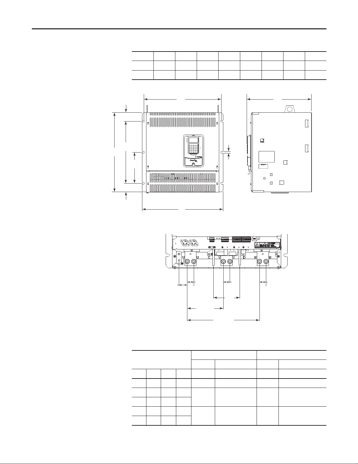
Chapter 1 Installation and Wiring
Dimensions of terminals U, V, and W are the same.
Dimensions are shown in mm and (in.)
Lifting flange
Note: 134 mm (5.3 in.) C and D terminals are installed on 460V AC input, 800 and 900 Hp, 575V AC input, 1000 Hp, and 690V AC input,
1100, 1200, 1250, and 1400 Hp drives only. All other frame D ratings have 100 mm (4.0 in.) C and D terminals.
PE C D
PE C D
80.5
(3.2)
Figure 5 - Frame D Dimensions - Right Side and Front Views
544
(21.4)
359
(14.1)
436.5
(17.2)
174
(6.9)
704
(27.7)
25
(1.0)
15
(0.6)
44.5
(1.8)
60
(2.4)
30
(1.2)
42
(1.7)
792
(31.2)
208
(8.2)
144
(5.7)
157.5
(6.2)
252.5
(10.0)
437.5
(17.2)
134
(5.3)
22.6
(0.9)
44.5
(1.8)
134
(5.3)
44.5
(1.8)
10.5
(0.4)
10
(0.4)
44.5
25
(1.8)
15
(1.0)
(0.6)
146
(5.7)60(2.4)
(1.2)
269.5
(10.6)
454.5
(18.0)
1250
(49.2)
32
(1.3)
30
44.5
27.8
(1.1)
(1.8)
100
(4.0)
100
(4.0)
22 Rockwell Automation Publication 20P-UM001I-EN-P - February 2013

215.225
(8.5)
103.25
(4.1)
1435 MAX
(56.5)
129
(5.1)
129
(5.1)
227.5
(9.0)
157.5
(6.2)
1230
(48.4)
16
(0.6)
10.5
(0.4)
10
(0.4)
10.5
(0.4)
127
(5.0)
531
(21.0)
541
(21.3)
94
(3.7)
127
(5.0)
127
(5.0)
127
(5.0)
Ø 23
(0.9)
127
(5.0)
127
(5.0)
127
(5.0)
127
(5.0)
94
(3.7)
94
(3.7)
94
(3.7)
Dimensions are shown in mm and (in.)
Mounting holes
Mounting holes
Lifting flange
Installation and Wiring Chapter 1
Figure 6 - Frame D Dimensions - Left Side and Back Views
Rockwell Automation Publication 20P-UM001I-EN-P - February 2013 23

Chapter 1 Installation and Wiring
Table 4 - Frame D - 230V AC Input Drive Weights
Drive w/ND
Rating Code
875
1K0
Weight - Regenerative Drives Weight - Non-regenerative Drives
Drive Drive & Packaging Drive Drive & Packaging
kg (lb) kg (lb) kg (lb) kg (lb)
203 (447.5) 281 (619.5) 152 (335.1) 230 (507.1)
Table 5 - Frame D - 460V AC Input Drive Weights
Drive w/ND
Rating Code
830
996
1K1
1K4
Weight - Regenerative Drives Weight - Non-regenerative Drives
Drive Drive & Packaging Drive Drive & Packaging
kg (lb) kg (lb) kg (lb) kg (lb)
202 (445.3) 280 (617.3) 152 (335.1) 230 (507.1)
215 (474.0) 293 (646.0) 165 (363.8) 243 (535.7)1K3
Table 6 - Frame D - 575V AC Input Drive Weights
Drive w/ND
Rating Code
810
1K0
1K2 215 (474.0) 293 (646.0) 165 (363.8) 243 (535.7)
1K3 222 (489.4) 300 (661.4) 172 (379.2) 250 (551.2)
1K6 241 (531.3) 319 (703.3) 191 (421.1) 269 (593.0)
Weight - Regenerative Drives Weight - Non-regenerative Drives
Drive Drive & Packaging Drive Drive & Packaging
kg (lb) kg (lb) kg (lb) kg (lb)
198 (436.5) 276 (608.5) 148 (326.3) 226 (498.2)
Table 7 - Frame D - 690V AC Input Drive Weights
Drive w/ND
Rating Code
678
791
904 200 (440.9) 278 (612.9) 150 (330.7) 228 (502.7)
1K0 202 (445.3) 280 (617.3)
1K1
1K2 165 (363.8) 243 (535.7)
1K4
1K5 191 (421.1) 269 (593.0)
24 Rockwell Automation Publication 20P-UM001I-EN-P - February 2013
Weight - Regenerative Drives Weight - Non-regenerative Drives
Drive Drive & Packaging Drive Drive & Packaging
kg (lb) kg (lb) kg (lb ) kg (lb)
198 (436.5) 276 (608.5) 148 (326.3) 226 (498.2)
215 (474.0) 293 (646.0)
241 (531.3) 319 (703.3)
152 (335.1) 230 (507.1)
172 (379.2) 250 (551.2)

Installation and Wiring Chapter 1
IMPORTANT
Lifting PowerFlex DC Drives
The dimensions and weights specified above must be taken into consideration
when mounting the device. Use the proper equipment to safely lift and hold the
weight of the drive while mounting.
ATTENTION: To guard against possible personal injury or equipment damage...
• Inspect all lifting hardware for proper attachment before lifting the drive.
• Do Not allow any part of the drive or lifting mechanism to make contact with
electrically charged conductors or components.
• Do Not subject the drive to high rates of acceleration or deceleration while
transporting to the mounting location or when lifting.
• Do Not allow personnel or their limbs directly underneath the drive when it is
being lifted and mounted.
Mounting Frame C and D Drives
All lifting equipment and lifting components (hooks, bolts, lifts, slings, chains,
etc.) must have a minimum
Verify that all mounting screws are properly tightened before and after drive
operation.
lifting capacity of 453.6 kg (1,000 lb).
1. Verify the hole pattern on the panel to which the drive will be mounted.
See Figure 4
2. Install the mounting hardware:
❏ For frame C drives, insert, but do not tighten, a bolt in one of the top
holes in the panel. The bolt must be fully threaded into the panel
before hanging the drive.
❏ For Frame D drives, insert, but do not tighten, the six bolts for the top
mounting flange on the drive into the panel. The bolts must be fully
threaded into the panel before hanging the drive.
3. To limit the pull in forces on the drive, the lifting devices connected to the
hooks must be long enough to make the angle between the chain or cable
and a vertical line extending up from the flange center less than 45° angle as
illustrated in Figure 7
❏ For frame C drives, insert the properly sized and rated lifting hooks
into the holes on the lifting flanges at the top of the drive. See Figure 7
on page 26
❏ For frame D drives, insert the properly sized lifting rod into the holes
on the lifting flanges at the top of the drive. See Figure 8
on page 21 or 22 on page 22.
on page 26 or Figure 8 on page 27.
.
on page 27.
Rockwell Automation Publication 20P-UM001I-EN-P - February 2013 25

Chapter 1 Installation and Wiring
Lifting flanges
Must be less
than 45° angle
Figure 7 - Lifting Frame C Drives
26 Rockwell Automation Publication 20P-UM001I-EN-P - February 2013
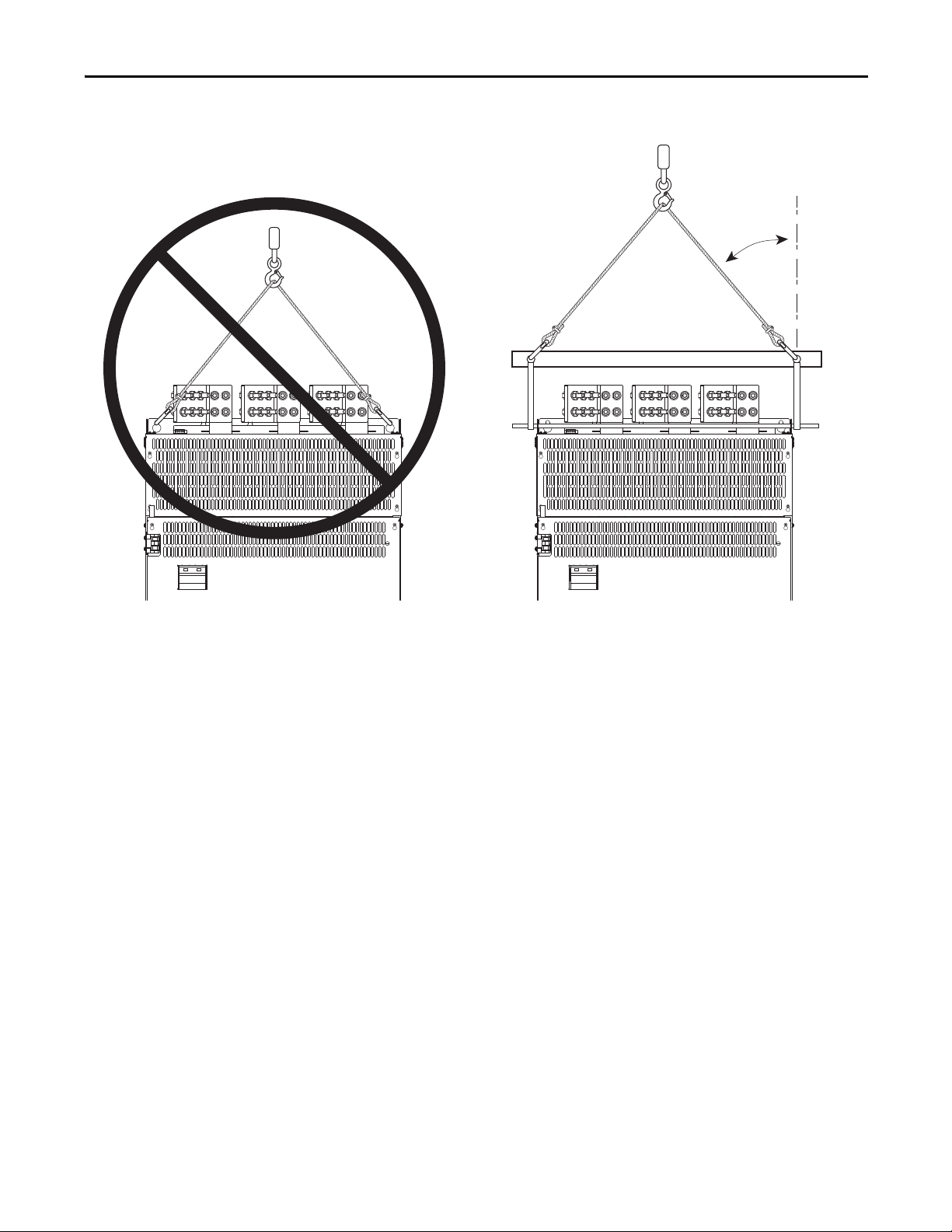
Figure 8 - Lifting Frame D Drives
Must be less
than 45° angle
Installation and Wiring Chapter 1
4. Lift the drive into place onto the bolt(s) installed in the panel.
5. Install the remaining bolts into the panel. Tighten M8 bolts to a minimum
torque of 15 N
•m (221.2 lb•in).
N
•m (132.7 lb•in) and M10 bolts to a minimum torque of 25
Rockwell Automation Publication 20P-UM001I-EN-P - February 2013 27

Chapter 1 Installation and Wiring
Removing the Drive Covers
The appropriate protective cover(s) must be removed in order to access the drive’s
power and I/O terminals. The upper cover only needs to be removed to install an
optional communication adapter and service the drive. (See Installing a
Communication Adapter on page 337
for information.)
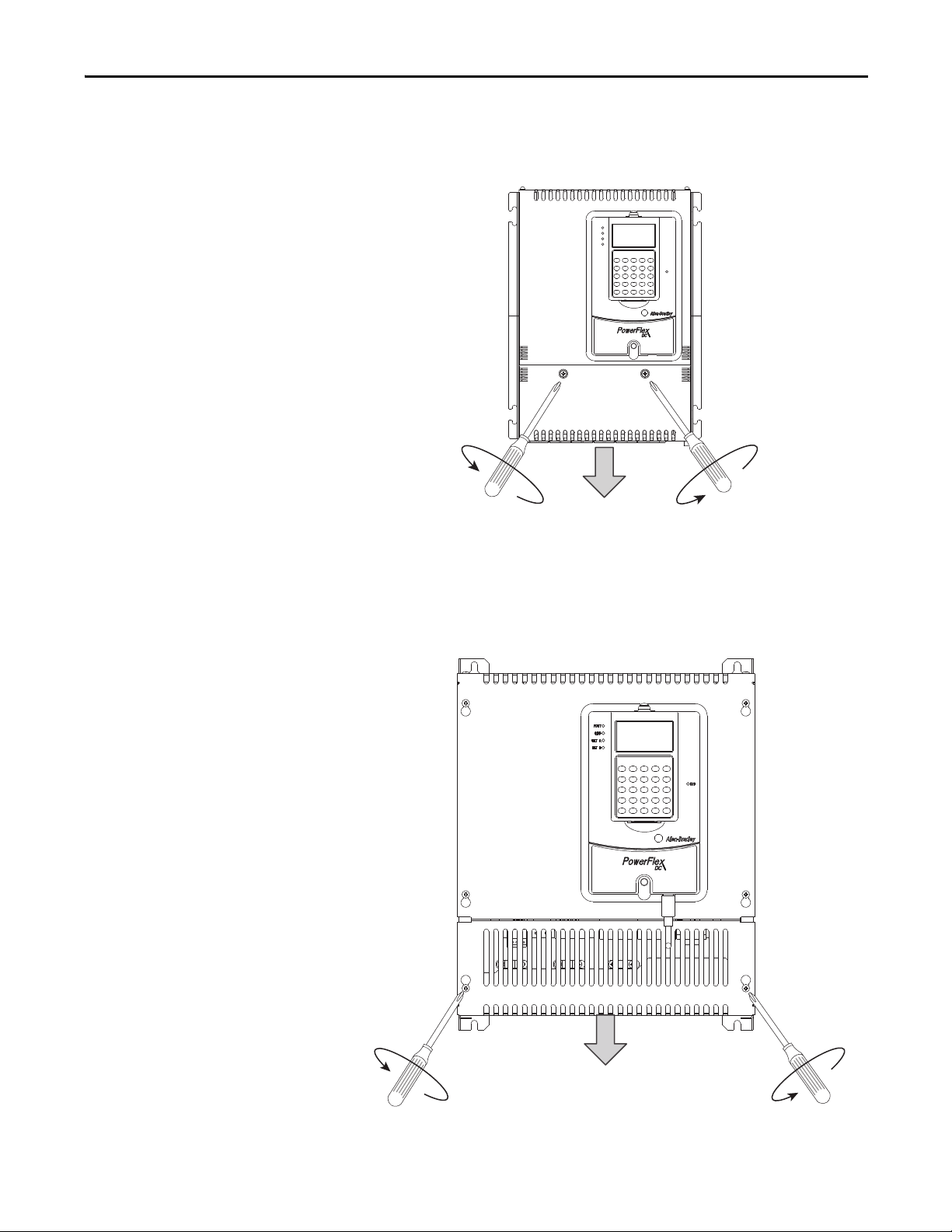
Frame A Drives
You must remove both the lower protective cover and the power terminal cover
on frame A drives to access the power terminals.
Remove the Power Terminal Cover
Remove the two screws as shown below and slide the cover down and off the
chassis.
28 Rockwell Automation Publication 20P-UM001I-EN-P - February 2013
Installation and Wiring Chapter 1
STS
PORT
MOD
NET A
NET B
Frame B Shown
Remove the Lower Protective Cover
Remove the two screws as shown below and, while gently lifting along the top
edge, slide the cover down and off the chassis.
Frame B and C Drives
Loosen, but do not remove, the two screws that secure the bottom cover. Then,
slide the cover down until the screw heads line up with the key holes and lift the
cover off the chassis.
Rockwell Automation Publication 20P-UM001I-EN-P - February 2013 29
Chapter 1 Installation and Wiring
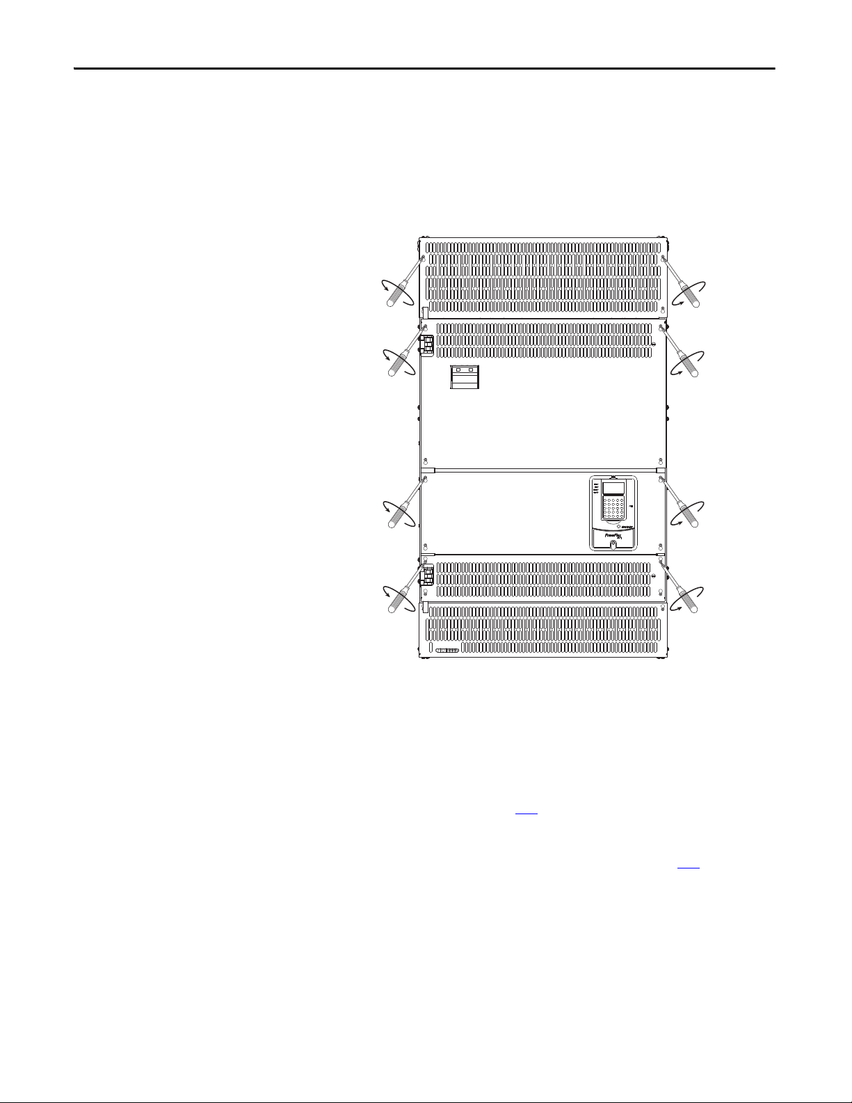
Frame D
For any protective cover, loosen, but do not remove, the Hexalobular head screws
that secure the cover to the drive frame. Then, slide the cover up until the screw
heads line up with the key holes and lift the cover off the chassis. The top and
bottom most covers are also secured by screws at the top and bottom of the drive,
respectively.
Isolation Transformers / Line Reactors
30 Rockwell Automation Publication 20P-UM001I-EN-P - February 2013
When connecting the drive directly to the main distribution system an isolation
transformer and/or 3…5% impedance AC line reactor must be used to guard
against system disturbance. If the isolation transformer provides the required
3…5% impedance, a line reactor is not required.
See Isolation Transformers on page 241
transformers.
See AC Input Line Reactors and AC Input Contactors on page 238
recommended AC line reactors. The type of line reactor used depends upon the
following:
• the current absorbed by the AC input
• the AC input voltage
• the relative short circuit voltage
• the AC input frequency
for a list of recommended isolation
for a list of
 Loading...