

Page 1

Installation Instructions
PowerFlex 400 AC Drive Packages for Fan & Pump
Applications
Page 2
Important User Information
IMPORTANT
Read this document and the documents listed in the additional resources section about installation, configuration, and
operation of this equipment before you install, configure, operate, or maintain this product. Users are required to
familiarize themselves with installation and wiring instructions in addition to requirements of all applicable codes, laws,
and standards.
Activities including installation, adjustments, putting into service, use, assembly, disassembly, and maintenance are required
to be carried out by suitably trained personnel in accordance with applicable code of practice.
If this equipment is used in a manner not specified by the manufacturer, the protection provided by the equipment may be
impaired.
In no event will Rockwell Automation, Inc. be responsible or liable for indirect or consequential damages resulting from the
use or application of this equipment.
The examples and diagrams in this manual are included solely for illustrative purposes. Because of the many variables and
requirements associated with any particular installation, Rockwell Automation, Inc. cannot assume responsibility or
liability for actual use based on the examples and diagrams.
No patent liability is assumed by Rockwell Automation, Inc. with respect to use of information, circuits, equipment, or
software described in this manual.
Reproduction of the contents of this manual, in whole or in part, without written permission of Rockwell Automation,
Inc., is prohibited.
Throughout this manual, when necessary, we use notes to make you aware of safety considerations.
WARNING: Identifies information about practices or circumstances that can cause an explosion in a hazardous environment,
which may lead to personal injury or death, property damage, or economic loss.
ATTENTION: Identifies information about practices or circumstances that can lead to personal injury or death, property
damage, or economic loss. Attentions help you identify a hazard, avoid a hazard, and recognize the consequence.
Identifies information that is critical for successful application and understanding of the product.
Labels may also be on or inside the equipment to provide specific precautions.
SHOCK HAZARD: Labels may be on or inside the equipment, for example, a drive or motor, to alert people that dangerous
voltage may be present.
BURN HAZARD: Labels may be on or inside the equipment, for example, a drive or motor, to alert people that surfaces may
reach dangerous temperatures.
ARC FLASH HAZARD: Labels may be on or inside the equipment, for example, a motor control center, to alert people to
potential Arc Flash. Arc Flash will cause severe injury or death. Wear proper Personal Protective Equipment (PPE). Follow ALL
Regulatory requirements for safe work practices and for Personal Protective Equipment (PPE).
Allen-Bradley, Rockwell Software, Rockwell Automation, and TechConnect are trademarks of Rockwell Automation, Inc.
Trademarks not belonging to Rockwell Automation are property of their respective companies.
Page 3

This manual contains new and updated information.
Summary of Changes
New and Updated Information
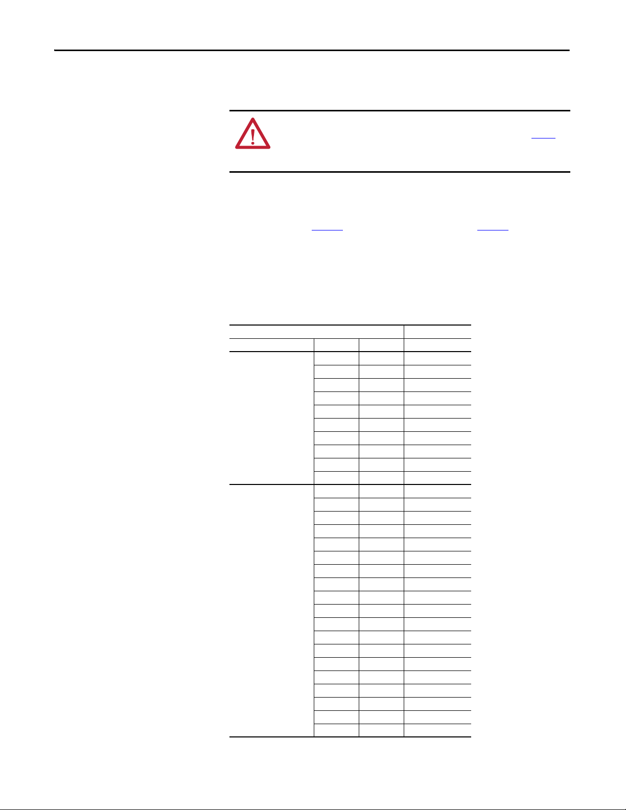
This table contains the changes made to this revision.
Top ic Pag e
Removed all content related to the discontinued 3 Contactor Basic Bypass with Disconnect Package
(Style C)
–
Rockwell Automation Publication 23C-IN001B-EN-P - June 2013 3
Page 4

Summary of Changes
Notes:
4 Rockwell Automation Publication 23C-IN001B-EN-P - June 2013
Page 5

Table of Contents
Preface
Main Input Disconnect Package
(Style A/M)
Who Should Use this Manual? . . . . . . . . . . . . . . . . . . . . . . . . . . . . . . . . . . . . . . 9
What Is Not in this Manual. . . . . . . . . . . . . . . . . . . . . . . . . . . . . . . . . . . . . . . . . 9
Additional Resources . . . . . . . . . . . . . . . . . . . . . . . . . . . . . . . . . . . . . . . . . . . . . 10
Manual Conventions . . . . . . . . . . . . . . . . . . . . . . . . . . . . . . . . . . . . . . . . . . . . . 10
General Precautions . . . . . . . . . . . . . . . . . . . . . . . . . . . . . . . . . . . . . . . . . . . . . . 11
Catalog Number Explanation . . . . . . . . . . . . . . . . . . . . . . . . . . . . . . . . . . . . . 12
Chapter 1
Style Explanation . . . . . . . . . . . . . . . . . . . . . . . . . . . . . . . . . . . . . . . . . . . . . . . . 13
Hardware Overview . . . . . . . . . . . . . . . . . . . . . . . . . . . . . . . . . . . . . . . . . . . . . . 13
Main Disconnect Switch (DS1) . . . . . . . . . . . . . . . . . . . . . . . . . . . . . . . 13
Main Circuit Breakers (CB1). . . . . . . . . . . . . . . . . . . . . . . . . . . . . . . . . . 13
Main Fuses (FU1-FU3) . . . . . . . . . . . . . . . . . . . . . . . . . . . . . . . . . . . . . . . 14
Electrical Installation . . . . . . . . . . . . . . . . . . . . . . . . . . . . . . . . . . . . . . . . . . . . . 15
Input Power Wiring . . . . . . . . . . . . . . . . . . . . . . . . . . . . . . . . . . . . . . . . . . 15
Output Power Wiring . . . . . . . . . . . . . . . . . . . . . . . . . . . . . . . . . . . . . . . . 16
Control and Signal Wiring . . . . . . . . . . . . . . . . . . . . . . . . . . . . . . . . . . . . 17
Parameter Defaults (Style A/M) . . . . . . . . . . . . . . . . . . . . . . . . . . . . . . . . . . 18
Drawing Index. . . . . . . . . . . . . . . . . . . . . . . . . . . . . . . . . . . . . . . . . . . . . . . . . . . 19
208V AC Input – Main Input Disconnect Drive Packages
(Style A/M) . . . . . . . . . . . . . . . . . . . . . . . . . . . . . . . . . . . . . . . . . . . . . . . . . 19
460V AC – Main Input Disconnect Drive Packages (Style A/M) 20
Schematic Drawings. . . . . . . . . . . . . . . . . . . . . . . . . . . . . . . . . . . . . . . . . . . . . . 22
Interconnect Drawings . . . . . . . . . . . . . . . . . . . . . . . . . . . . . . . . . . . . . . . . . . . 29
Layout Drawings. . . . . . . . . . . . . . . . . . . . . . . . . . . . . . . . . . . . . . . . . . . . . . . . . 34
Outline Drawings . . . . . . . . . . . . . . . . . . . . . . . . . . . . . . . . . . . . . . . . . . . . . . . . 70
3 Contactor Full Feature Bypass with
Disconnect Package (Style B/N)
Chapter 2
Style Explanation . . . . . . . . . . . . . . . . . . . . . . . . . . . . . . . . . . . . . . . . . . . . . . . . 87
Hardware Overview . . . . . . . . . . . . . . . . . . . . . . . . . . . . . . . . . . . . . . . . . . . . . . 87
Main Disconnect Switch (DS1) . . . . . . . . . . . . . . . . . . . . . . . . . . . . . . . 87
Main Circuit Breakers (CB1). . . . . . . . . . . . . . . . . . . . . . . . . . . . . . . . . . 87
Main Fuses (FU1-FU3) . . . . . . . . . . . . . . . . . . . . . . . . . . . . . . . . . . . . . . . 88
Contactors (DIC, DOC, BC) . . . . . . . . . . . . . . . . . . . . . . . . . . . . . . . . . 89
Motor Overload Relay (OL). . . . . . . . . . . . . . . . . . . . . . . . . . . . . . . . . . . 89
Control Transformer (T1) . . . . . . . . . . . . . . . . . . . . . . . . . . . . . . . . . . . . 91
Bypass Control Interface (CP1) . . . . . . . . . . . . . . . . . . . . . . . . . . . . . . . 91
Electrical Installation . . . . . . . . . . . . . . . . . . . . . . . . . . . . . . . . . . . . . . . . . . . . . 92
Input Power Wiring . . . . . . . . . . . . . . . . . . . . . . . . . . . . . . . . . . . . . . . . . . 92
Output Power Wiring . . . . . . . . . . . . . . . . . . . . . . . . . . . . . . . . . . . . . . . . 93
Control and Signal Wiring . . . . . . . . . . . . . . . . . . . . . . . . . . . . . . . . . . . . 94
Customer Connections. . . . . . . . . . . . . . . . . . . . . . . . . . . . . . . . . . . . . . . . . . . 95
Interlock. . . . . . . . . . . . . . . . . . . . . . . . . . . . . . . . . . . . . . . . . . . . . . . . . . . . . 95
Freeze/Fire Stat . . . . . . . . . . . . . . . . . . . . . . . . . . . . . . . . . . . . . . . . . . . . . . 95
Autostart . . . . . . . . . . . . . . . . . . . . . . . . . . . . . . . . . . . . . . . . . . . . . . . . . . . . 95
Rockwell Automation Publication 23C-IN001B-EN-P - June 2013 5
Page 6

Table of Contents
Bypass . . . . . . . . . . . . . . . . . . . . . . . . . . . . . . . . . . . . . . . . . . . . . . . . . . . . . . . 95
Purge . . . . . . . . . . . . . . . . . . . . . . . . . . . . . . . . . . . . . . . . . . . . . . . . . . . . . . . . 96
Bypass Running . . . . . . . . . . . . . . . . . . . . . . . . . . . . . . . . . . . . . . . . . . . . . . 96
Operating Modes. . . . . . . . . . . . . . . . . . . . . . . . . . . . . . . . . . . . . . . . . . . . . . . . . 96
Parameter Defaults (Style B/N) . . . . . . . . . . . . . . . . . . . . . . . . . . . . . . . . . . . 97
Drawing Index . . . . . . . . . . . . . . . . . . . . . . . . . . . . . . . . . . . . . . . . . . . . . . . . . . . 98
208V AC – 3 Contactor Full Feature Bypass with Disconnect
Package (Style B/N) . . . . . . . . . . . . . . . . . . . . . . . . . . . . . . . . . . . . . . . . . . 98
460V AC – 3 Contactor Full Feature Bypass with Disconnect
Package (Style B/N) . . . . . . . . . . . . . . . . . . . . . . . . . . . . . . . . . . . . . . . . . . 99
Schematic Drawings . . . . . . . . . . . . . . . . . . . . . . . . . . . . . . . . . . . . . . . . . . . . . 101
Interconnect Drawings . . . . . . . . . . . . . . . . . . . . . . . . . . . . . . . . . . . . . . . . . . 117
Layout Drawings . . . . . . . . . . . . . . . . . . . . . . . . . . . . . . . . . . . . . . . . . . . . . . . . 122
Outline Drawings . . . . . . . . . . . . . . . . . . . . . . . . . . . . . . . . . . . . . . . . . . . . . . . 159
Chapter 3
Mechanical Installation
Electrical Installation
Supplemental Information
Mounting Considerations. . . . . . . . . . . . . . . . . . . . . . . . . . . . . . . . . . . . . . . . 177
Environment . . . . . . . . . . . . . . . . . . . . . . . . . . . . . . . . . . . . . . . . . . . . . . . . 177
Maximum Surrounding Air Temperature. . . . . . . . . . . . . . . . . . . . . . 177
Minimum Mounting Clearances . . . . . . . . . . . . . . . . . . . . . . . . . . . . . . 177
Lifting and Mounting the Drive . . . . . . . . . . . . . . . . . . . . . . . . . . . . . . . . . . 180
Watts Loss. . . . . . . . . . . . . . . . . . . . . . . . . . . . . . . . . . . . . . . . . . . . . . . . . . . . . . 181
Weights . . . . . . . . . . . . . . . . . . . . . . . . . . . . . . . . . . . . . . . . . . . . . . . . . . . . . . . . 182
Chapter 4
Power Wire Size Requirements . . . . . . . . . . . . . . . . . . . . . . . . . . . . . . . . . . . 185
Power Terminal Block Specification . . . . . . . . . . . . . . . . . . . . . . . . . . . . . . 185
Control and Signal Wiring . . . . . . . . . . . . . . . . . . . . . . . . . . . . . . . . . . . . . . . 186
Installing Input Power Wiring. . . . . . . . . . . . . . . . . . . . . . . . . . . . . . . . . . . . 186
Installing Output Power Wiring . . . . . . . . . . . . . . . . . . . . . . . . . . . . . . . . . . 187
Installing an Optional Transformer or Reactor. . . . . . . . . . . . . . . . . . . . . 187
Installing Fuses for Branch Circuit Protection. . . . . . . . . . . . . . . . . . 188
Installing the Required External/Separate Input Disconnect . . . . 189
Installing Input/Output Power Wiring. . . . . . . . . . . . . . . . . . . . . . . . 189
Appendix A
Specifications . . . . . . . . . . . . . . . . . . . . . . . . . . . . . . . . . . . . . . . . . . . . . . . . . . . 191
Appendix B
Replacement Parts
6 Rockwell Automation Publication 23C-IN001B-EN-P - June 2013
Common Parts. . . . . . . . . . . . . . . . . . . . . . . . . . . . . . . . . . . . . . . . . . . . . . . . . . 193
Disconnect Parts . . . . . . . . . . . . . . . . . . . . . . . . . . . . . . . . . . . . . . . . . . . . . . . . 194
Bypass Parts. . . . . . . . . . . . . . . . . . . . . . . . . . . . . . . . . . . . . . . . . . . . . . . . . . . . . 196
Enclosure Parts. . . . . . . . . . . . . . . . . . . . . . . . . . . . . . . . . . . . . . . . . . . . . . . . . . 198
Page 7

Preface
The purpose of this manual is to provide basic information needed to install,
®
start-up and troubleshoot PowerFlex
Packages for Fan & Pump Applications.
User documentation for the PowerFlex 400 Drive Packages for Fan & Pump
Applications includes these Installation Instructions and the PowerFlex 400 User
Manual, Publication 22C-UM001…. Both manuals are required to properly
install and operate the PowerFlex 400 Adjustable Frequency AC Drive Packages
for Fan & Pump Applications.
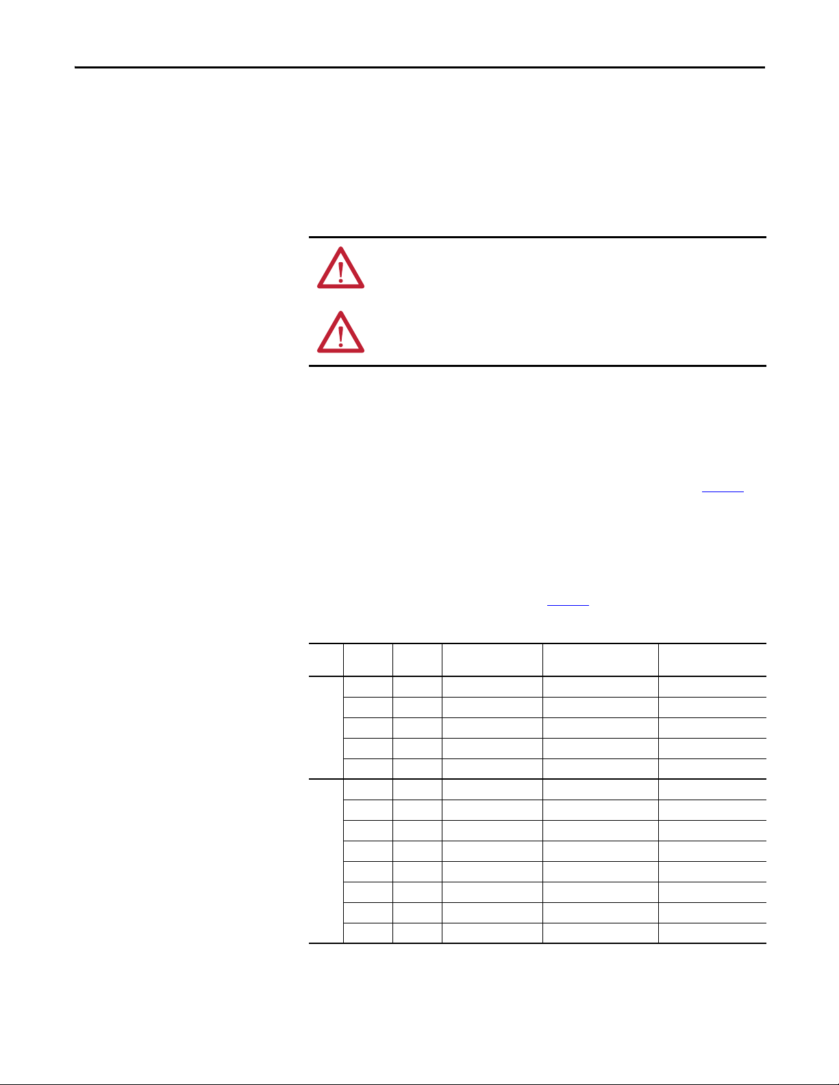
Top ic Pag e
Who Should Use this Manual? 7
What Is Not in this Manual 7
Additional Resources 8
Manual Conventions 8
General Precautions 9
Catalog Number Explanation 10
400 Adjustable Frequency AC Drive
Who Should Use this Manual?
What Is Not in this Manual
This manual is intended for qualified personnel. You must be able to program
and operate Adjustable Frequency AC Drive devices. In addition, you must have
an understanding of the parameter settings and functions.
The PowerFlex 400 Adjustable Frequency AC Drive Packages for Fan & Pump
Applications Installation Instructions is designed to provide only basic
installation and operation information. For this reason, the following topics have
not been included:
• Specifications
• Troubleshooting
• Startup
• Programming and Parameters
Please refer to the PowerFlex 400 User Manual for detailed drive information.
Rockwell Automation Publication 23C-IN001B-EN-P - June 2013 7
Page 8
Preface
Additional Resources
These documents contain additional information concerning related products
from Rockwell Automation.
Resource Description
Wiring and Grounding Guidelines for Pulse Width Modulated
(PWM) AC Drives, publication DRIVES-IN001
Preventive Maintenance of Industrial Control and Drive
System Equipment, publication DRIVES-TD001
PowerFlex 400 User Manual, publication 22C-UM001 Provides the basic information needed to install, start-
Industrial Automation Wiring and Grounding Guidelines,
publication 1770-4.1
Product Certifications website, http://www.ab.com Provides declarations of conformity, certificates, and
Provides the basic information needed to properly wire
and ground Pulse Width Modulated (PWM) AC drives.
Contains a checklist that can be used as a guide to
perform preventive maintenance on variable frequency
AC drives.
up and troubleshoot the PowerFlex 400 Adjustable
Frequenc y AC Drive.
Provides general guidelines for installing a Rockwell
Automation industrial system.
other certification details.
You can view or download publications at
http:/www.rockwellautomation.com/literature/
. To order paper copies of
technical documentation, contact your local Allen-Bradley distributor or
Rockwell Automation sales representative.
Manual Conventions
• To help differentiate parameter names and LCD display text from other
text, the following conventions will be used:
• Parameter Names will appear in [brackets].
For example: [DC Bus Voltage].
• Display Text will appear in “quotes.” For example: “Enabled.”
• The following words are used throughout the manual to describe an
action:
Word Mean ing
Can Possible, able to do something
Cannot Not possible, not able to do something
May Permitted, allowed
Must Unavoidable, you must do this
Shall Required and necessary
Should Recommended
Should Not Not recommended
8 Rockwell Automation Publication 23C-IN001B-EN-P - June 2013
Page 9
General Precautions
Preface
ATTENTION: This drive contains ESD (Electrostatic Discharge) sensitive parts and
assemblies. Static control precautions are required when installing, testing,
servicing or repairing this assembly. Component damage may result if ESD
control procedures are not followed. If you are not familiar with static control
procedures, reference A-B publication 8000-4.5.2, “Guarding Against
Electrostatic Damage” or any other applicable ESD protection handbook.
ATTENTION: An incorrectly applied or installed drive can result in component
damage or a reduction in product life. Wiring or application errors, such as,
undersizing the motor, incorrect or inadequate AC supply, or excessive ambient
temperatures may result in malfunction of the system.
ATTENTION: Only qualified personnel familiar with adjustable frequency AC
drives and associated machinery should plan or implement the installation, startup and subsequent maintenance of the system. Failure to comply may result in
personal injury and/or equipment damage.
ATTENTION: To avoid an electric shock hazard, verify that the voltage on the bus
capacitors has discharged before performing any work on the drive. Measure the
voltage at the drive (Refer to the PowerFlex 400 User Manual for test point
locations). The voltage must be zero.
Rockwell Automation Publication 23C-IN001B-EN-P - June 2013 9
Page 10
Preface
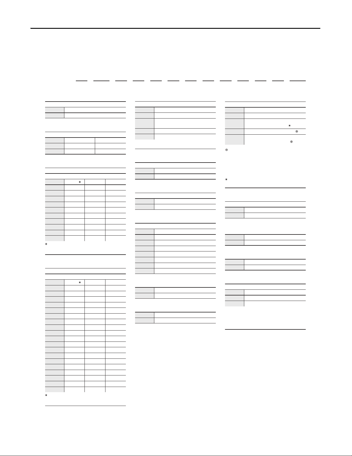
Position
1-345 6-8 9 101112131415161718 19+
23C
– D 038 A 1 0 3 N N B A N N -LR
abcdefghijklmn
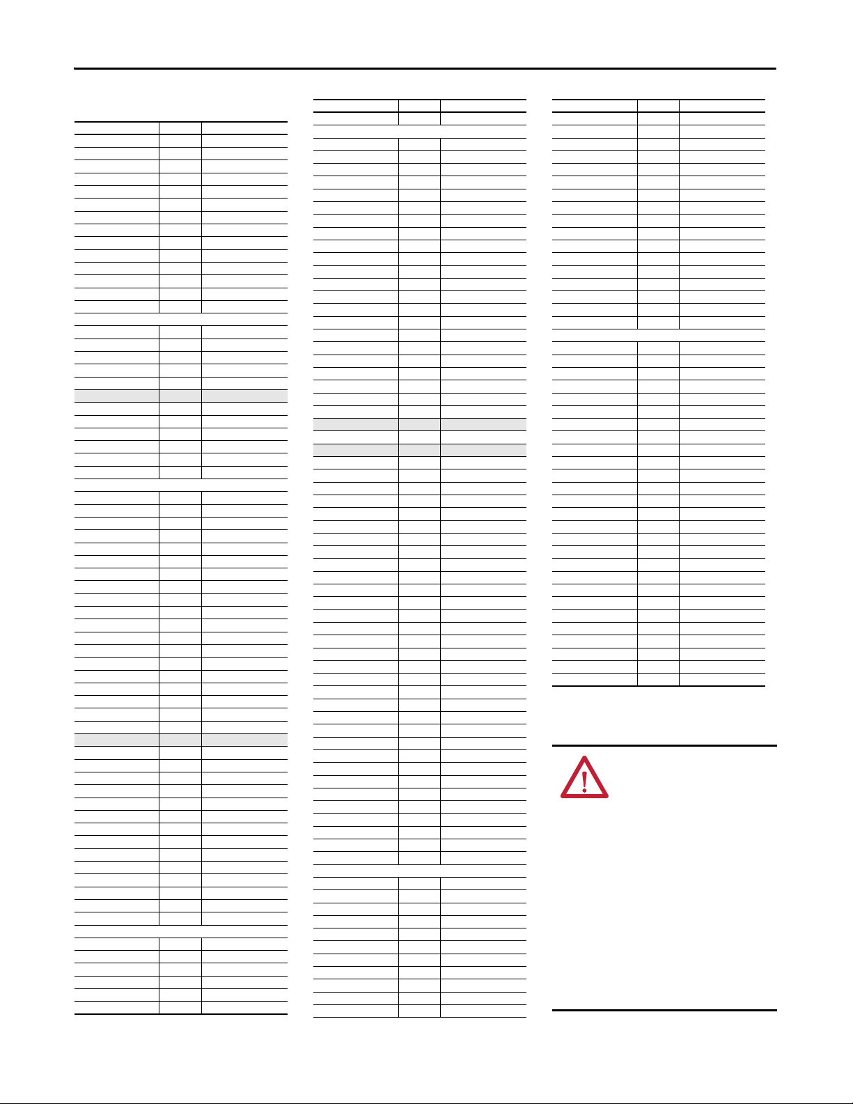
a
Drive
Code Type
23C PowerFlex 400
b
Voltage Rating
Code Voltage Ph.
X 208V ac 3
D 480V ac 3
c1
Rating
208V, 60Hz Input
Code Amps kW (Hp) Frame
012 12 2.2 (3.0) C
017 16.8 3.7 (5.0) C
024 24 5.5 (7.5) C
033 30.8 7.5 (10) C
049 46.2 11 (15) D
065 64 15 (20) D
075 75 18.5 (25) D
090 88 22 (30) D
120 114 30 (40) E
145 143 37 (50) E
Congured drive amp ratings may dier from
stand-alone drive ratings. Congured drives
sized per NEC motor amps.
d
Enclosure
Code Enclosure
A NEMA/UL Type 1
H
NEMA/UL Type 12 with Fan and
Filter
X NEMA/UL Type 3R ‡
E NEMA/UL Type 4 ‡
‡ Designed for maximum ambient temperature of
40° C with no direct sunlight exposure.
e
HIM
Code Interface Module
1 Fixed Keypad
f
Emission Class
Code Rating
0 Not Filtered
j
Package
Code Description
A Main Input Disconnect
B
3 Contactor Full Feature Bypass
with Disconnect
M
Main Input Circuit Breaker
N
3 Contactor Full Feature Bypass
with Circuit Breaker
Available with all ratings in NEMA/UL Type 12,
3R, or 4 enclosures (Position d = H, X, or E)
and 160-250 kW (250-350 Hp) ratings in
NEMA/UL Type 1 enclosures (Position d = A).
k
Control
Code Description
A Single Motor
l
Code Rating
N Reserved
c2
Rating
460V, 60Hz Input
Code Amps kW (Hp) Frame
6P0 4.8 2.2 (3.0) C
010 7.6 4.0 (5.0) C
012 11 5.5 (7.5) C
017 14 7.5 (10) C
022 21 11 (15) C
030 27 15 (20) C
038 34 18.5 (25) D
045 40 22 (30) D
060 52 30 (40) D
072 65 37 (50) E
088 77 45 (60) E
105 96 55 (75) E
142 124 75 (100) E
170 156 90 (125) F
208 180 110 (150) F
260 240 132 (200) G
310 302 160 (250) G
370 361 200 (300) H
460 414 250 (350) H
Congured amp ratings may dier from standalone drive ratings. Congured drives sized per
NEC motor amps.
g
Version
Code Version
3 RS485
B BACnet Adapter
C ControlNet Adapter
D DeviceNet Adapter
E EtherNet/IP Adapter
L LonWorks Adapter
P PROFIBUS DP Adapter
h
Code Rating
N Reserved
i
Code Rating
N Reserved
m
Code Rating
N Reserved
n
Options
Code Description
-LR 3% Input Line Reactor §
-E5
Space Heater - Local Power ♣
§ 3% Input Line Reactor not available for all
package styles. Consult product selection
tables for additional detail.
♣ Available with NEMA/UL Type 3R and 4
enclosures only.
‡ Not available with all ratings at 460V. Consult
product selection tables for details.
‡
Not available with all ratings at 460V. Consult
product selection tables for details.
Catalog Number Explanation
The PowerFlex 400 Adjustable Frequency AC Drive Packages for Fan & Pump
Applications catalog numbering scheme is shown below.
10 Rockwell Automation Publication 23C-IN001B-EN-P - June 2013
Page 11

Chapter 1
Main Input Disconnect Package (Style A/M)
This chapter describes the features and operation for the Main Input Disconnect
Package (Style A/M).
Top ic Pa ge
Hardware O verview 11
Electrical Installation 13
Parameter Defaults (Style A/M) 16
Drawing Index 17
Schematic Drawings 20
Interconnect Drawings 27
Layout Drawings 32
Outline Drawings 68
Style Explanation
Hardware Overview
• Style A = Fused Disconnect
• Style M = Circuit Breaker
The Main Input Disconnect Package (Style A/M) combines an Adjustable
Frequency AC Drive with a means for disconnecting input power within a single
package. Input power is connected to the PowerFlex drive through a door
interlocked fuse disconnect switch or circuit breaker.
Main Disconnect Switch (DS1)
An Allen-Bradley Bulletin 194R Fused Disconnect Switch with lockable rotary
mounted operator handle is provided. The disconnect switch is designed to meet
disconnect switch requirements for branch circuit protection. The door
mounted handle accepts up to three (3) padlocks.
Main Circuit Breakers (CB1)
An Allen-Bradley Bulletin 140U circuit breaker with lockable rotary mounted
operator handle is provided. The circuit breaker is designed to meet circuit
breaker requirements for branch circuit protection. The door-mounted handle
accepts up to three (3) padlocks.
Rockwell Automation Publication 23C-IN001B-EN-P - June 2013 11
Page 12
Chapter 1 Main Input Disconnect Package (Style A/M)
Main Fuses (FU1-FU3)
ATT EN TI ON : Most codes require that upstream branch circuit protection be
provided to protect input power wiring. Install the fuses recommended in Tab l e 1
Do not exceed the fuse ratings. Failure to observe this precaution could result in
damage to, or destruction of, the equipment.
Input line branch circuit protection fuses must be used to protect the input
power lines. If input fuses are not provided with your drive, recommended fuse
values are shown in Ta b l e 1
for one drive per branch circuit. No other load may be applied to that fused
circuit.
The recommended fuse type for all PowerFlex 400 Drive Packages for Fan &
Pump Applications is UL Class J.
Table 1 - Fuse Recommendations
Drive Rating Fuse Rating
Input Voltage kW Hp Amps
208V AC – 3-Phase 2.2 3.0 20
460V AC – 3-Phase 2.2 3.0 10
. The input fuse ratings listed in Ta b l e 1 are applicable
3.7 5.0 20
5.5 7.5 35
7.5 10 40
11 15 80
15 20 100
18.5 25 125
22 30 150
30 40 200
37 50 250
4.0 5.0 15
5.5 7.5 20
7.5 10 20
11 15 35
15 20 35
18.5 25 60
22 30 70
30 40 80
37 50 100
45 60 150
55 75 175
75 100 200
90 125 250
110 150 350
132 200 400
160 250 500
200 300 600
250 350 700
.
12 Rockwell Automation Publication 23C-IN001B-EN-P - June 2013
Page 13
Main Input Disconnect Package (Style A/M) Chapter 1
Electrical Installation
Input Power Wiring
Use 75 °C rated copper conductors only for customer power wiring.
Refer to the PowerFlex 400 User Manual for additional detailed information
about input power wiring recommendations and selection.
ATT EN TI ON : Protect the contents of the options cabinet from metal chips and
other debris while drilling the conduit openings. Failure to observe this
precaution could result in damage to, or destruction of, the equipment.
ATT EN TI ON : Do not route signal and control wiring with power wiring in the
same conduit. This can cause interference with drive operation. Failure to observe
this precaution could result in damage to, or destruction of, the equipment.
To connect AC input power to the drive package:
❏ 1. Select the proper wire size according to NEC and all applicable local codes
and standards. Note that you must punch openings in the Option Cabinet
of the desired conduit size, following NEC and all applicable local codes
and standards. Power terminal block specifications are listed in Ta b l e 2
.
❏ 2. Connect the three-phase AC input power leads (three-wire VAC) to the
appropriate terminals. Connect the AC input power leads to terminals
L1, L2, L3 on the fused disconnect switch.
❏ 3. Tighten the AC input terminal power terminals to the proper torque
according to drive type as shown in Ta b l e 2
Table 2 - AC Input Power Terminal Block Specifications
Volts ACkW Hp Maximum Wire Size
2
208V 2.2…3.7 3.0…5.0 8.4 mm
5.5…7.5 7.5…10 16.0 mm
11…15 15…20 33.6 mm
18.5…30 25…40 250 MCM 10.0 mm
37 50 350 MCM 35.0 mm
460V 2.2…7.5 3.0…10 8.4 mm
11…18.5 15…25 16.0 mm
22…37 30…50 33.6 mm
45…75 60…100 250 MCM 10.0 mm
90…110 125…150 (2) 350 MCM (2) 10.0 mm
132 200 (2) 350 MCM (2) 35.0 mm
160…200 250…300 (2) 350 MCM (2) 70.0 mm
250 350 (2) 400 MCM (2) 70.0 mm
(8 AWG) 2.5 mm2 (14 AWG) 4.0 N•m (35 lb•in)
2
(4 AWG) 2.5 mm2 (14 AWG) 4.0 N•m (35 lb•in)
2
(2 AWG) 2.5 mm2 (14 AWG) 17.5 N•m (155 lb•in)
2
(8 AWG) 2.5 mm2 (14 AWG) 4.0 N•m (35 lb•in)
2
(4 AWG) 2.5 mm2 (14 AWG) 4.0 N•m (35 lb•in)
2
(2 AWG) 2.5 mm2 (14 AWG) 17.5 N•m (155 lb•in)
(1)
Minimum Wire Size Recommended Torque
.
2
(6 AWG) 31.1 N•m (275 lb•in)
2
(1/0 AWG) 31.1 N•m (275 lb•in)
2
(6 AWG) 31.1 N•m (275 lb•in)
2
(6 AWG) 31.1 N•m (275 lb•in)
2
(1/0 AWG) 31.1 N•m (275 lb•in)
2
(3/0 AWG) 31.1 N•m (275 lb•in)
2
(3/0 AWG) 31.1 N•m (275 lb•in)
(1) Maximum/minimum sizes that the terminal block will accept - these are not recommendations. If national or local codes require
sizes outside the range, lugs may be used.
Rockwell Automation Publication 23C-IN001B-EN-P - June 2013 13
Page 14

Chapter 1 Main Input Disconnect Package (Style A/M)
❏ 1. Wire the three-phase AC output power motor leads by routing them
Output Power Wiring
Refer to the PowerFlex 400 User Manual for additional detailed information
about output power wiring recommendations and selection.
ATT EN TI ON : Unused wires in conduit must be grounded at both ends to avoid a
possible shock hazard caused by induced voltages. Also, if a drive sharing a
conduit is being serviced or installed, all drives using this conduit should be
disabled to eliminate the possible shock hazard from cross-coupled motor leads.
Failure to observe these precautions could result in bodily injury.
ATT EN TI ON : Do not route signal and control wiring with power wiring in the
same conduit. This can cause interference with drive operation. Failure to observe
this precaution could result in damage to, or destruction of, the equipment.
To connect AC output power wiring from the drive to the motor:
according to the drive option type. Note that you must punch openings in
the option cabinet of the desired conduit size, following NEC and all
applicable local codes and standards. Power terminal block specifications
are listed in Ta b l e 3
.
Do not route more than three sets of motor leads through a single conduit.
This will minimize cross-talk that could reduce the effectiveness of noise
reduction methods. If more than three drive/motor connections per
conduit are required, shielded cable must be used. If possible, each conduit
should contain only one set of motor leads.
❏ 2. Connect the three-phase AC output power motor leads to terminals
U, V, W (T1, T2, T3) on the power terminal block located on the drive.
❏ 3. Tighten the three-phase AC output power terminals to the proper torque
according to drive type as shown in Ta b l e 3
Table 3 - AC Output Power Terminal Block Specifications
Volt s ACkW Hp Maximum Wire Size
2
208V 2.2…7.5 3.0…10 8.4 mm
11…22 15…30 33.6 mm
30…37 40…50 33.6 mm
460V 2.2…15 3.0…20 8.4 mm
18.5…30 25…40 33.6 mm
37…45 50…60 33.6 mm
55…75 75…100 107.2 mm
90…110 125…150 300 MCM 70.0 mm
132…160 200…250 300 MCM 107.2 mm
200…250 300…350 500 MCM 300 MCM 40.0 N•m (354 lb•in)
(8 AWG) 1.3 mm2 (16 AWG) 3.7 N•m (33 lb•in)
2
(2 AWG) 8.4 mm2 (8 AWG) 5.1 N•m (45 lb•in)
2
(2 AWG) 2.5 mm2 (14 AWG) 17.5 N•m (155 lb•in)
2
(8 AWG) 1.3 mm2 (16 AWG) 3.7 N•m (33 lb•in)
2
(2 AWG) 8.4 mm2 (8 AWG) 5.1 N•m (45 lb•in)
2
(2 AWG) 3.5 mm2 (12 AWG) 5.6 N•m (49.5 lb•in)
2
(4/0 AWG) 53.5 mm2 (1/0 AWG) 19.5 N•m (173 lb•in)
(1)
.
Minimum Wire Size Recommended Torque
2
(3/0 AWG) 19.5 N•m (173 lb•in)
2
(4/0 AWG) 29.4 N•m (260 lb•in)
(1) Maximum/minimum sizes that the terminal block will accept - these are not recommendations. If national or local codes require
sizes outside the range, lugs may be used.
14 Rockwell Automation Publication 23C-IN001B-EN-P - June 2013
Page 15

Main Input Disconnect Package (Style A/M) Chapter 1
Control and Signal Wiring
Refer to the PowerFlex 400 User Manual for additional detailed information
about control and signal wiring.
The Control I/O Terminal Block (TB1) and Relay Terminal Block (TB2)
located on the drive Main Control Board provide terminals for interfacing
customer supplied control inputs and outputs. All analog and discrete control
wiring will be made at these terminals. Typical customer control and signal wiring
is shown on the Interconnect Drawings Figure 8
28
.
To connect control and signal wiring to the drive package:
❏ 1. Wire the control and signal leads by routing them according to the drive
option type. Note that you must punch openings in the option cabinet of
the desired conduit size, following NEC and all applicable local codes and
standards. I/O terminal block specifications are listed in Ta b l e 4
Control and signal wires should be separated from power wires by at least
0.3 meters (1 foot).
on page 27 and Figure 9 on page
.
❏ 2. Connect the control and signal wiring to the I/O terminals located on the
drive.
❏ 3. Tighten the I/O terminals to the proper torque according to drive type as
shown in Ta b l e 4
Table 4 - I/O Terminal Block Specifications
Voltage Rating Maximum Wire Size
208…460V AC 1.3 mm
(1) Maximum/minimum sizes that the terminal block will accept - these are not recommendations.
.
(1)
Minimum Wire Size Torque
2
(16 AWG) 0.13 mm2 (26 AWG) 0.5…0.8 N•m (4.4…7 lb•in)
Rockwell Automation Publication 23C-IN001B-EN-P - June 2013 15
Page 16
Chapter 1 Main Input Disconnect Package (Style A/M)
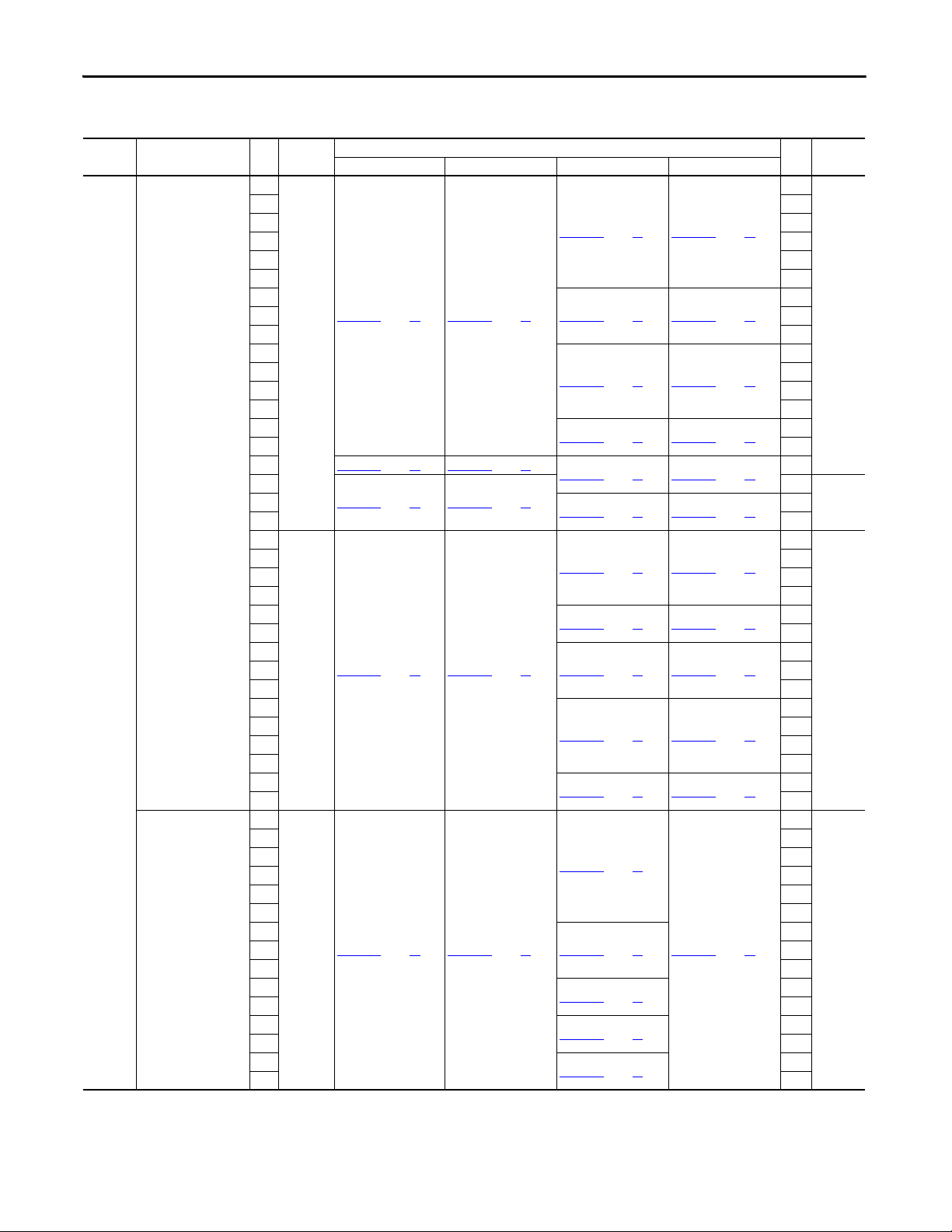
Parameter Defaults (Style A/M)
Parameter Name Number Default
Output Freq b001 Read Only
Commanded Freq b002 Read Only
Output Current b003 Read Only
Output Voltage b004 Read Only
DC Bus Voltage b005 Read Only
Drive Status b006 Read Only
Fault 1 Code b007 Read Only
Process Display b008 Read Only
Output Power b010 Read Only
Elapsed MWh b011 Read Only
Elapsed Run Time b012 Read Only
Torque Current b013 Read Only
Drive Temp b014 Read Only
Elapsed kWh b015 Read Only
Motor NP Volts P031 Drive Rated Volts
Motor NP Hertz P032 60 Hz
Motor OL Current P033 Drive Rated Amps
Minimum Freq P034 0.0 Hz
Maximum Freq P035 60 Hz
Start Source P036 6 “2-W Lvl/Enbl”
Stop Mode P037 1 “Coast, CF”
Speed Reference P038 2 “Analog In1”
Accel Time 1 P039 20.00 Secs
Decel Time 1 P040 20.00 Secs
Reset To Defalts P041 0 “Ready/Idle”
Auto Mode P042 1 “Hnd-Off-Auto”
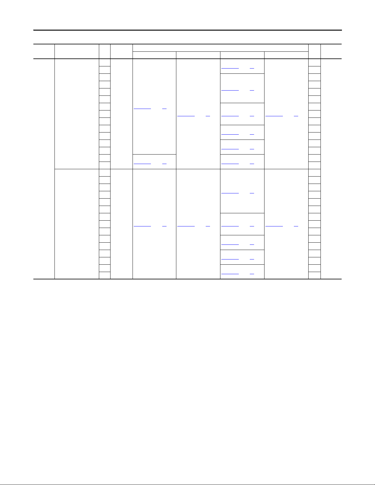
Digital In1 Sel T051 1 “Purge”
Digital In2 Sel T052 3 “Local”
Digital In3 Sel T053 10 “Clear Fault”
Digital In4 Sel T054 4 “Comm Port”
Relay Out1 Sel T055 0 “Ready/Fault”
Relay Out1 Level T056 0.0
Relay 1 On Time T058 0.0 Secs
Relay 1 Off Time T059 0.0 Secs
Relay Out2 Sel T060 2 “MotorRunning”
Relay Out2 Level T061 0.0
Relay 2 On Time T063 0.0 Secs
Relay 2 Off Time T064 0.0 Secs
Opto Out Sel T065 1 “At Frequency”
Opto Out Level T066 0.0
Opto Out Logic T068 0 “Normally Open”
Analog In 1 Sel T069 2 “0-10V”
Analog In 1 Lo T070 0.0%
Analog In 1 Hi T071 100.0%
Analog In 1 Loss T072 0 “Disabled”
Analog In 2 Sel T073 1 “4-20 mA”
Analog In 2 Lo T074 0.0%
Analog In 2 Hi T075 100.0%
Analog In 2 Loss T076 0 “Disabled”
Sleep-Wake Sel T077 0 “Disabled”
Sleep Level T078 10.0%
Sleep Time T079 0.0 Secs
Wake Level T080 15.0%
Wake Time T081 0.0 Secs
Analog Out1 Sel T082 0 “OutFreq 0-10”
Analog Out1 High T083 100%
Analog Out1 Setpt T084 0.0%
Analog Out2 Sel T085 1 “OutCurr 0-10”
Analog Out2 High T086 100%
Analog Out2 Setpt T087 0.0%
Language C101 1 “English”
Comm Format C102 0 “RTU 8-N-1”
Comm Data Rate C103 3 “9600”
Comm Node Addr C104 100
Comm Loss Action C105 0 “Fault”
Comm Loss Time C106 5.0 Secs
(1)
(1)
Parameter Name Number Default
Comm Write Mode C107 0 “Save”
Purge Frequency A141 5.0 Hz
Internal Freq A142 60.00 Hz
Preset Freq 0 A143 0.0 Hz
Preset Freq 1 A144 5.0 Hz
Preset Freq 2 A145 10.0 Hz
Preset Freq 3 A146 20.0 Hz
Accel Time 2 A147 30.00 Secs
Decel Time 2 A148 30.00 Secs
S Curve % A149 20%
PID Trim Hi A150 60.0 Hz
PID Trim Lo A151 0.0 Hz
PID Ref Sel A152 0 “PID Disabled”
PID Feedback Sel A153 0 “Analog In 1”
PID Prop Gain A154 0.01
PID Integ Time A155 2.0 Secs
PID Diff Rate A156 0.00
PID Setpoint A157 0.0%
PID Deadband A158 0.0%
PID Preload A159 0.0 Hz
Process Factor A160 30.0
Auto Rstrt Tries A163 0
Auto Rstrt Delay A164 1.0 Secs
Start At PowerUp A165 1 “Enabled”
Reverse Disable A166 1 “Rev D isabled”
Flying Star t En A167 1 “Enabled”
PWM Frequency A168 4.0 kHz
PWM Mode A169 1 “2-Phase”
Boost Select A170 4 “45.0, VT”
Start Boost A171 2.5%
Break Voltage A172 25.0%
Break Frequency A173 15.0 Hz
Maximum Voltage A174 Drive Rated Volts
Slip Hertz @ FLA A175 2.0 Hz
DC Brake Time A176 0.0 Secs
DC Brake Level A177 Drive Rated Amps
DC Brk Time@Strt A178 0 (Disabled)
Current Limit 1 A179 Drive Rated Amps
Current Limit 2 A180 Drive Rated Amps
Motor OL Select A181 0 “No Derate”
Drive OL Mode A182 3 “B oth-PWM 1st”
SW Current Trip A183 0.0 (Disabled)
Load Los s Level A184 0 .0 (Disab led)
Load Loss Time A185 0 Secs
Stall Fault Time A186 0 “60 Seconds”
Bus Reg Mode A187 1 “Enabled”
Skip Frequency 1 A188 0 Hz
Skip Freq Band 1 A189 0.0 H z
Skip Frequency 2 A190 0 Hz
Skip Freq Band 2 A191 0.0 H z
Skip Frequency 3 A192 0 Hz
Skip Freq Band 3 A193 0.0 H z
Compensati on A194 1 “Ele ctrical”
Reset Meters A195 0 “Ready/Idle”
Tes tp oin t S el A1 96 4 00
Fault Clear A197 0 “Ready/Idle”
Program Lock A198 0 “Unlocked”
Motor NP Poles A199 4
Relay Out3 Sel R221 0 “Rea dy/Fault”
Relay Out3 Level R222 0.0
Relay Out4 Sel R224 0 “Rea dy/Fault”
Relay Out4 Level R225 0.0
Relay Out5 Sel R227 0 “Rea dy/Fault”
Relay Out5 Level R228 0.0
Relay Out6 Sel R230 0 “Rea dy/Fault”
Relay Out6 Level R231 0.0
Relay Out7 Sel R233 0 “Rea dy/Fault”
Relay Out7 Level R234 0.0
Relay Out8 Sel R236 0 “Rea dy/Fault”
(1)
(1)
Parameter Name Num ber Default
Relay Out8 Level R237 0.0
Aux Motor Mode R239 0 “Disabled”
Aux Motor Qty R240 1 “1 Aux Mtr”
Aux 1 Start Freq R241 50.0 Hz
Aux 1 Stop Freq R242 25.0 Hz
Aux 1 Ref Add R243 0.0%
Aux 2 Start Freq R244 50.0 Hz
Aux 2 Stop Freq R245 25.0 Hz
Aux 2 Ref Add R246 0.0%
Aux 3 Start Freq R247 50.0 Hz
Aux 3 Stop Freq R248 25.0 Hz
Aux 3 Ref Add R249 0.0%
Aux Start Delay R250 5.0 Secs
Aux Stop Delay R251 3.0 Secs
Aux Prog Delay R252 0.50 Secs
Aux AutoSwap Tme R253 0.0 Hr
Aux AutoSwap Lvl R254 50.0%
Control Source d301 Read Only
Contrl In Status d302 Read Only
Comm Status d303 Read Only
PID Setpnt Displ d304 Read Only
Analog In 1 d305 Read Only
Analog In 2 d306 Read Only
Fault 1 Code d307 Read Only
Fault 2 Code d308 Read Only
Fault 3 Code d309 Read Only
Fault 1 Time-hr d310 Read Only
Fault 1 Time-min d311 Read Only
Fault 2 Time-hr d312 Read Only
Fault 2 Time-min d313 Read Only
Fault 3 Time-hr d314 Read Only
Fault 3 Time-min d315 Read Only
Elapsed Time -hr d3 16 Rea d Only
Elapsed Time -min d317 Re ad Only
Output Powr Fctr d318 Read Only
Testpoint Data d319 Read Only
Control SW Ver d320 Read Only
Drive Type d321 Read Only
Output Speed d322 Read Only
Output RPM d323 Read Only
Fault Frequency d324 Read Only
Fault Current d325 Read Only
Fault Bus Volts d326 Read Only
Status @ Fault d327 Read Only
(1) The default values of these parameter s differ from Factory
Defaults. Setting P041 [Reset To Defalts] to 1 “Factory Rset” will
change these parameter settings to the defaults list in the
PowerFlex 400 User Manual.
ATTENTION: Parame ter
A165 [Start At PowerUp] ships
from the factory enabled. This
feature allows a Run
command to automatically
cause the drive to resume
running at commanded speed
after drive input power is
restored. Equipment damage
and/or personal injury may
result if this parameter is used
in an inappropriate
application. Do not use this
function without considering
applicable local, national and
international codes, standards,
regulations or industry
guidelines.
16 Rockwell Automation Publication 23C-IN001B-EN-P - June 2013
Page 17
Main Input Disconnect Package (Style A/M) Chapter 1
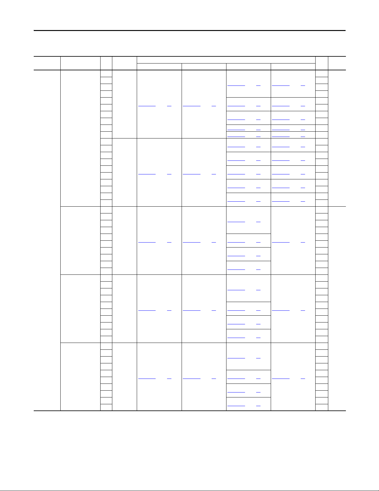
Drawing Index 208V AC Input – Main Input Disconnect Drive Packages (Style A/M)
Input
Voltag e
208V AC
Type Hp Input Line
NEMA/UL Type 1
NEMA/UL Type 12
NEMA/UL Type 4
NEMA/UL Type 3R
Reactor
3
5 5
7.5 7.5
10 10
15
No 98D00697
20 20
25
30 30
40 95D00760 35 95D00693 71 40
50 95D00776
3
5 5
7.5
10 10
15
Yes 98D00756 21 97D00754 28
20 20
25
30 30
40
50 50
3
5 5
7.5 7.5
10 10
15
With or
With out
20 20
25
30 30
40
50 50
3
5 5
7.5 7.5
10 10
15
With or
With out
20 20
25
30 30
40
50 50
3
5 5
7.5 7.5
10 10
15
With or
With out
20 20
25
30 30
40
50 50
Drawing Hp Style
SchematicPage InterconnectPage LayoutPage OutlinePage
3
95D00758 32 95D00689 68
20 97D00696 27
98D01535 24 97D01548 31
25 97D01548 31
98D01537
24 97D01548 31
98D01535
95D00759
33 95D00691 69
34 95D00692 70
95D00775
36 95D00694 72 50
95D00791 40 95D00690 76
41 95D00753 77
95D00792
95D01367
42 95D01359 78
95D01368 43 95D01360 79
44 95D01361 80
95D01369
95D01575 46
47
95D01576
95D02451
48
95D02497 49
95D01563 54
95D01565 55
56
95D02455
95D02495
57
95D01553 61
95D01554 62
95D02453 63
64
95D02493
95D01552 82
95D01551 83
95D01550 84
15
25
3
7.5
15
25
40
3
15
25
40
3
15
25
40
3
15
25
40
A
A & M
Rockwell Automation Publication 23C-IN001B-EN-P - June 2013 17
Page 18
Chapter 1 Main Input Disconnect Package (Style A/M)
Input
Voltag e
460V AC
Type Hp Input Line
NEMA/UL Type 1
NEMA/UL Type 12
Reactor
3
5 5
7.5 7.5
10 10
15 15
20 20
25
30 30
40 40
50
No
60 60
75 75
100 100
125
150 150
200 98D01888
250
350 350
3
5 5
7.5 7.5
10 10
15
20 20
25
Yes 98D00756
30 30
40 40
50
60 60
75 75
100 100
125
150 150
3
5 5
7.5 7.5
10 10
15 15
20 20
25
With or
30 30
With out
40 40
50
60 60
75
100 100
125
150 150
460V AC – Main Input Disconnect Drive Packages (Style A/M)
Drawing Hp Style
SchematicPage InterconnectPage LayoutPage OutlinePage
3
95D00758 32 95D00689 68
25
98D00697
20 97D00696 27
22 97D01890 29
98D01887
23 97D01889 30
21 97D00754 28
98D01535 24 97D01548 31
95D00759
33 95D00691 69
95D00760
35 95D00693 71
95D01262
37 95D01264 73
95D01862 38 95D01866 74
95D01864 39 95D01868 75
95D00791 40 95D00690 76
95D00792
41 95D00753 77
95D01367
42 95D01359 78
95D01369
44 95D01361 80
95D01370
45 95D01362 81
95D01575 46
95D01576
47
95D02470
50
95D02476 51
95D01579
52
95D01552 82
50
125
200
250
300
3
15
25
50
125
3
25
50
75
125
A
M300
A
A & M
18 Rockwell Automation Publication 23C-IN001B-EN-P - June 2013
Page 19
Main Input Disconnect Package (Style A/M) Chapter 1
Input
Voltag e
460V AC
Type Hp Input Line
NEMA/UL Type 4
NEMA/UL Type 3R
Reactor
3
5 5
7.5
10 10
15 15
20 20
25
With or
30 30
With out
40 40
50
60 60
75
100 100
125
150 150
3
5 5
7.5 7.5
10 10
15 15
20 20
25
With or
30 30
With out
40 40
50
60 60
75
100 100
125
150 150
Drawing Hp Style
SchematicPage InterconnectPage LayoutPage OutlinePage
3
7.5
25
50
75
125
3
25
50
75
125
A & M
98D01537 25
97D01548 31
98D01538
26 95D01568 60
98D01535 24 97D01548 31
95D02442 53
95D01563
54
95D01565
55
95D02469
58
95D02475
59
95D01553 61
95D01554
62
95D02468
65
95D02474
66
95D01557
67
95D01551 83
95D01550 84
Rockwell Automation Publication 23C-IN001B-EN-P - June 2013 19
Page 20
Chapter 1 Main Input Disconnect Package (Style A/M)
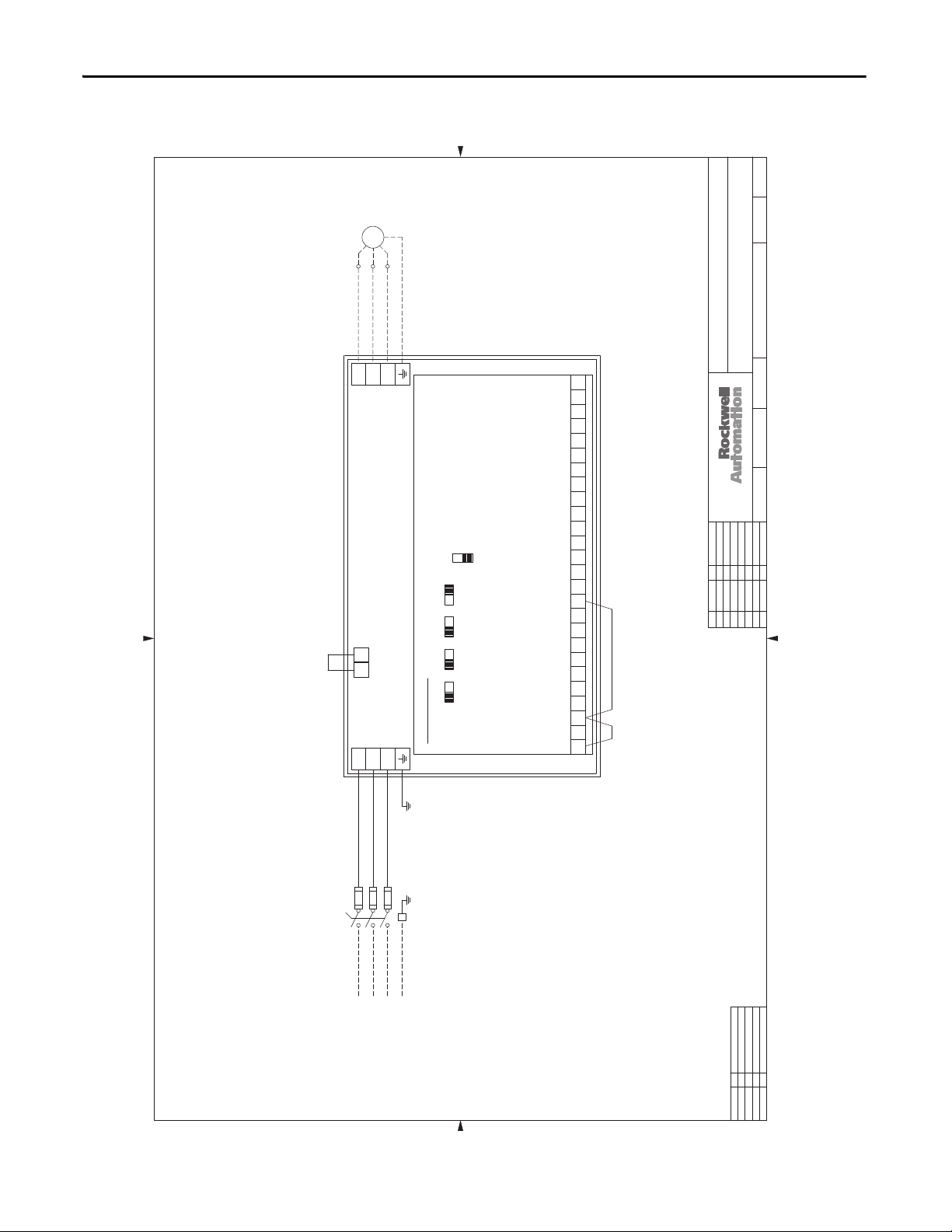
Schematic Drawings
0203040506070809101112131415161718192021222324252627282930313233343536373839404142
01
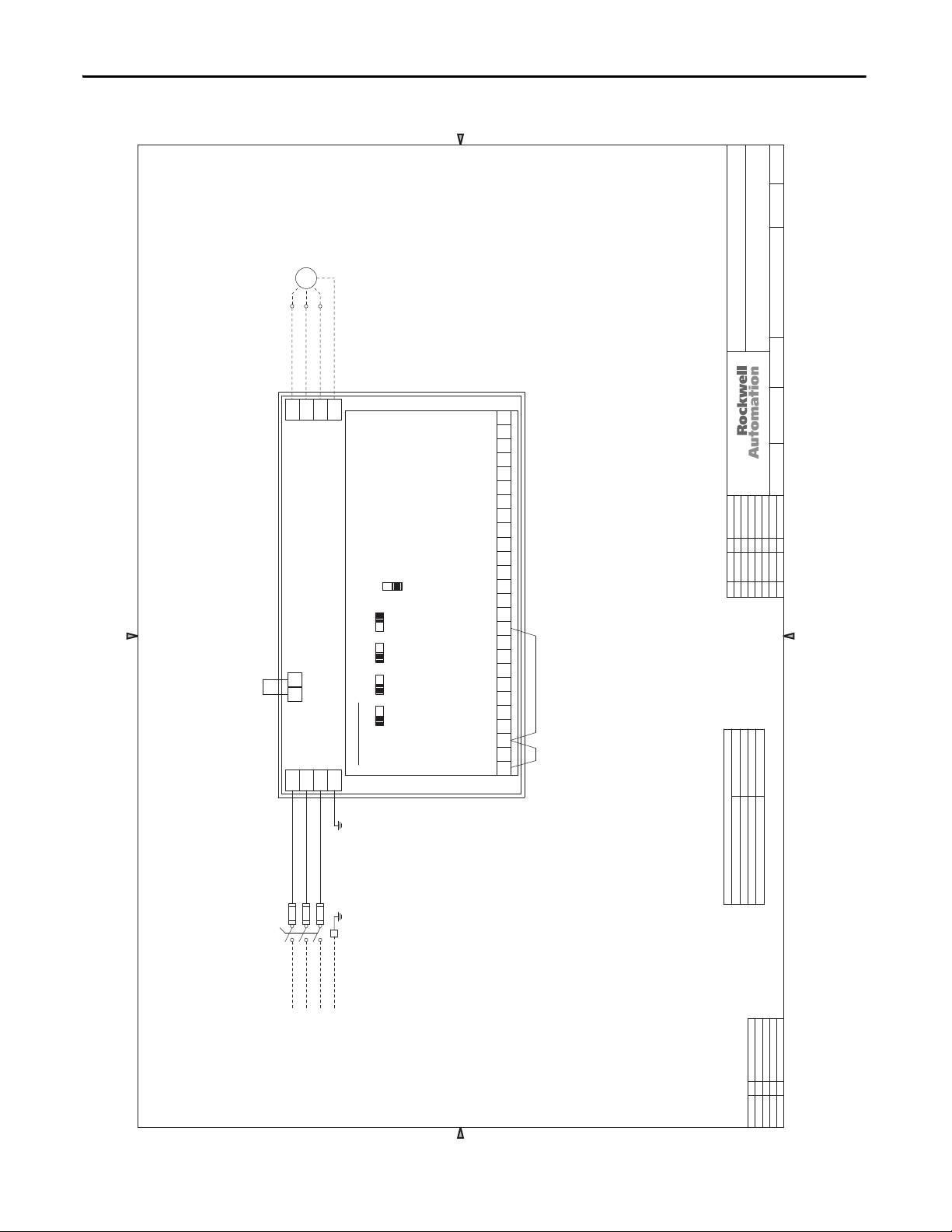
Figure 1 - 3.0…50 Hp, 208V AC & 3.0…150 Hp, 460V AC Drives - NEMA/UL Type 1
98D00697
MOTOR
T3T1T2
GND
V/T2
U/T1
POWERFLEX 400
P2P1
R/L1
S/L2
W/T3
T/L3
DM1
CONTROL BOARD
AI2
10V 20MA
10V 20MA
AO2
10V 20MA
AO1 AI1
10V 20MA
SRC
SNK
#2 RELAY N.C.
#2 RELAY COMMON
#2 RELAY N.O. (MOTOR RUNNING)
#1 RELAY N.C.
#1 RELAY COMMON
#1 RELAY N.O. (READY/FAULT)
RJ-45 SHIELD
OPTO OUTPUT (AT FREQUENCY)
ANALOG COM #2
ANALOG INPUT #2
ANALOG OUTPUT #2 (OUTPUT CURRENT 0-10V)
ANALOG OUTPUT #1 (FREQUENCY 0-10V)
151110 12 13 14 16 17 1918 20 R3R1 R2 R4 R5 R6
ANALOG COM. #1
ANALOG INPUT #1
+ 10VDC
+ 24VDC
OPTO COMMON
DIGITAL COMMON
DIGITAL INPUT 4 (COMM PORT)
DIGITAL INPUT 3 (CLEAR FAULT)
DIGITAL INPUT 2 (LOCAL)
DIGITAL INPUT 1 (PURGE)
DIGITAL COMMON
SOFTWARE ENABLE
RUN/FWD
FUNCTION LOSS
JUMPERJUMPER
1 324 75 6 89
11
11/24/04
SH.NEXT
NO.SH.
-
98D00697
NO.DATE DATE
DWG.ENG.
SCHEMATIC DRAWING - PF400, STYLE A
3-50HP @ 208VAC & 3-150HP @ 460VAC
TITLE
THIS DRAWING IS THE PROPERTY OF ROCKWELL AUTOMATION, INC.
OR ITS SUBSIDIARIES AND MAY NOT BE COPIED, USED OR DISCLOSED FOR ANY
PURPOSE EXCEPT AS AUTHORIZED IN WRITING BY ROCKWELL AUTOMATION, INC.
JFH/ACI
4/5/04
CHK. BY
JRF/ACI
4/5/04
DATE
DR. BY
DATEREV. BY ECN/CR. NO.
A 11/24/04 JRF
B 2/3/05 JRF
C 6/7/07 REH
D 8/10/07 REH
E 1/31/11 JLD
L11
L13
L12
FU3
FU2
FU1
01
02030405060708
11
10
09
DS1
SWITCH
MAIN DISC.
12131415161718
L1
L2
f POWER
INCOMING
3
LG
L3
192021
22232425262728
30
29
20 Rockwell Automation Publication 23C-IN001B-EN-P - June 2013
31
32333435363738
39
APPROVAL
DESIGN REVIEW
FOR MANUFACTURING
BYDATE
41
40
AS SHIPPED
AS COMMISSIONED
42
Page 21
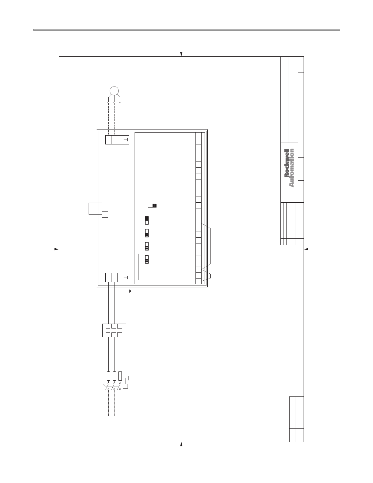
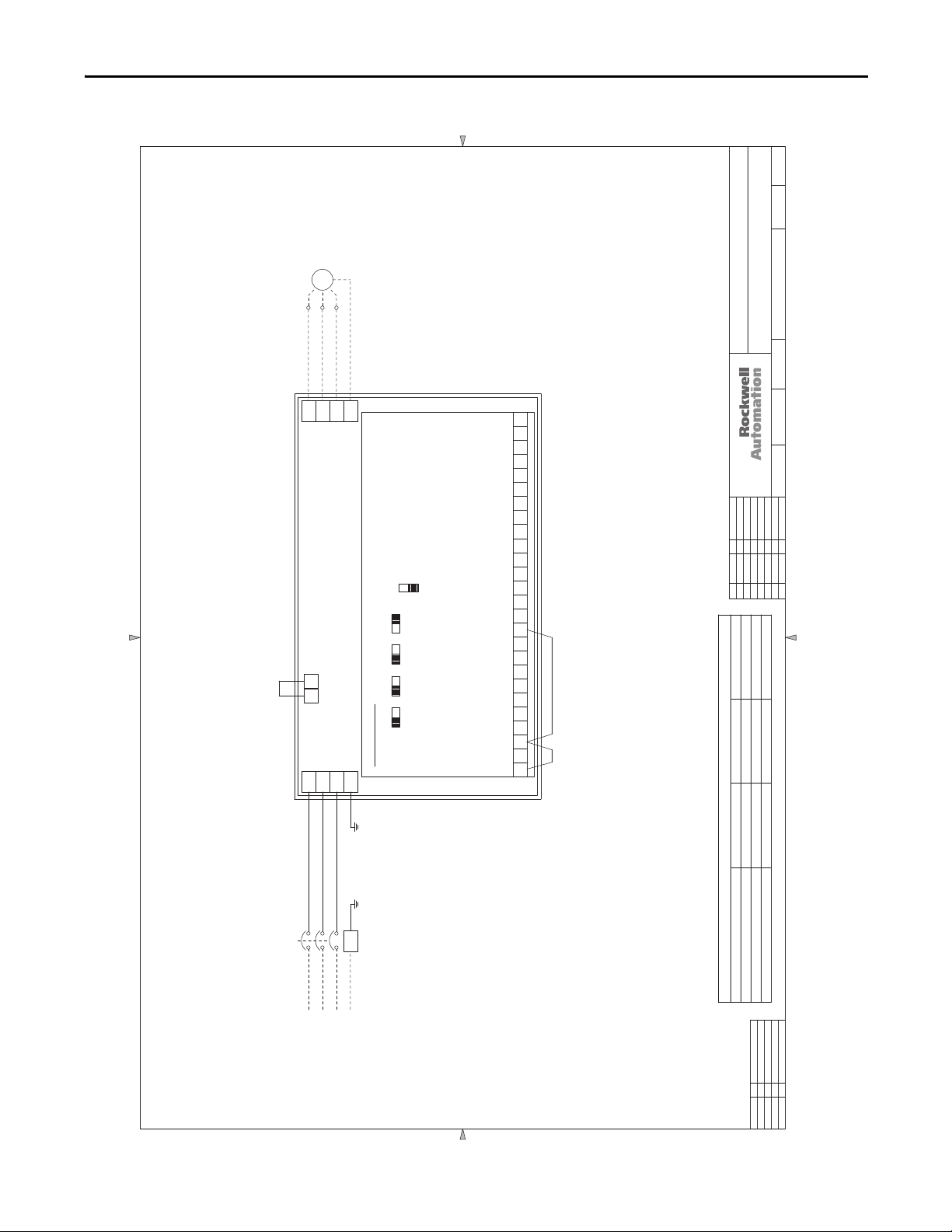
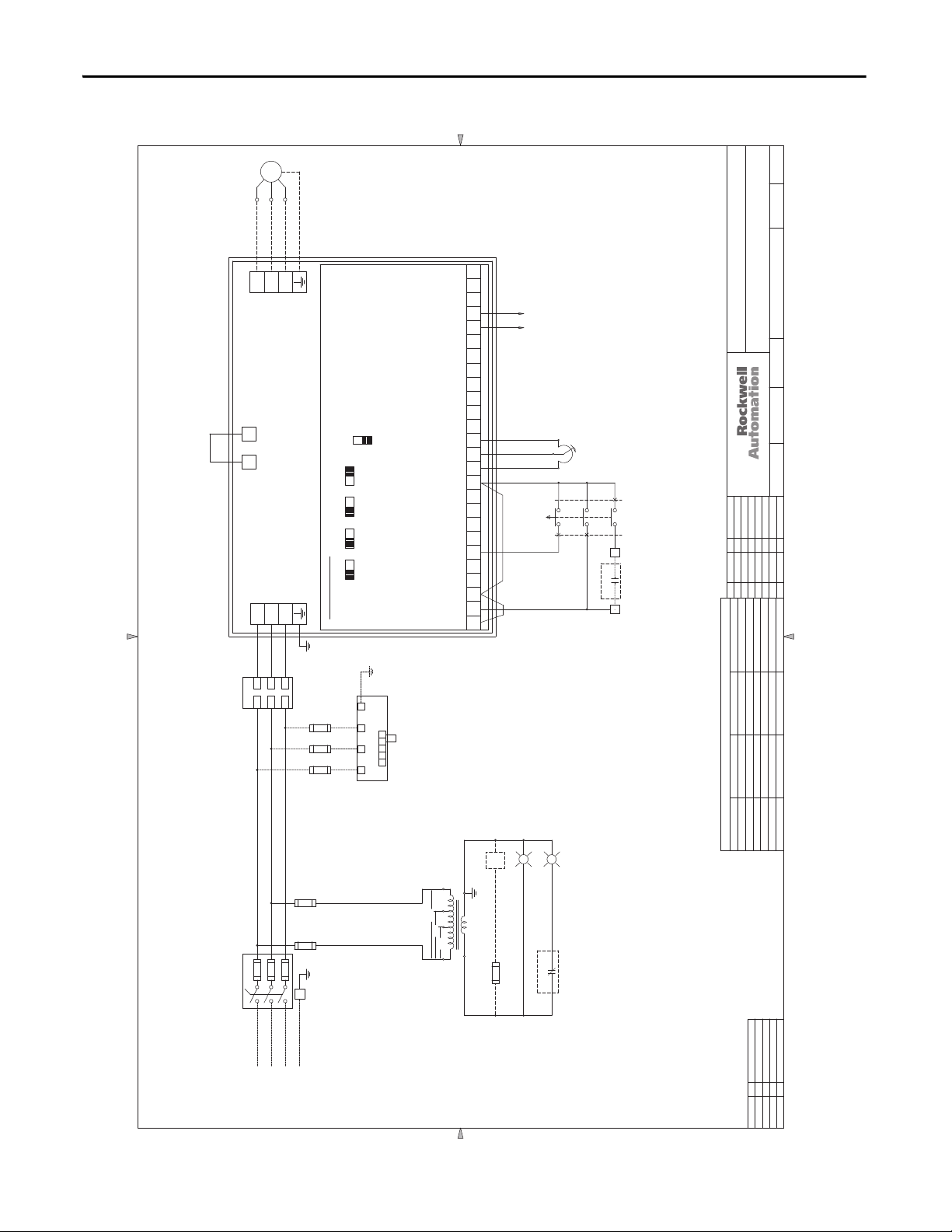
Figure 2 - 3.0…50 Hp, 208V AC & 3.0…150 Hp, 460V AC Drives with Line Reactor - NEMA/UL Type 1
01
02030405060708
09
10
11
12131415161718
192021
30
31
40
41
0203040506070809101112131415161718192021222324252627282930313233343536373839404142
01
DATEREV. BY ECN/CR. NO.
A 11/24/04 JRF
B 5/18/05 JRF
C 6/7/07 REH
D 1/31/11 JLD
APPROVAL
DESIGN REVIEW
FOR MANUFACTURING
AS SHIPPED
AS COMMISSIONED
BYDATE
SH.NEXT
NO.SH.
-
DWG.ENG.
TITLE
CHK. BY
NO.DATE DATE
DR. BY
DATE
THIS DRAWING IS THE PROPERTY OF ROCKWELL AUTOMATION, INC.
OR ITS SUBSIDIARIES AND MAY NOT BE COPIED, USED OR DISCLOSED FOR ANY
PURPOSE EXCEPT AS AUTHORIZED IN WRITING BY ROCKWELL AUTOMATION, INC.
11
SCHEMATIC DRAWING - PF400, STYLE A, W/LINE REACTOR
3-50HP @ 208VAC & 3-150HP @ 460VAC
98D00756
JRF/ACI
5/17/04
JFH/ACI
5/17/04
11/24/04
CONTROL BOARD
RUN/FWD
FUNCTION LOSS
SOFTWARE ENABLE
1 23
R/L1
T/L3
S/L2
FU3
FU2
FU1
L23
L22
L21
19
OPTO OUTPUT (AT FREQUENCY)
+ 10VDC
+ 24VDC
ANALOG INPUT #1
ANALOG COM. #1
ANALOG OUTPUT #1 (FREQUENCY 0-10V)
ANALOG OUTPUT #2 (OUT CURRENT 0-10V)
ANALOG INPUT #2
ANALOG COM #2
DIGITAL INPUT 1 (PURGE)
DIGITAL COMMON
DIGITAL INPUT 2 (ANALOC 1 IN)
DIGITAL INPUT 3 (CLEAR FAULT)
DIGITAL COMMON
DIGITAL INPUT 4 (COMM PORT)
OPTO COMMON
54 76 981110 151312 14 1716 18
10V 20MA
AI2
10V 20MA10V 20MA
AO1
AO2 AI1
10V 20MA
SNK
SRC
POWERFLEX 400
P1 P2
#1 RELAY N.O. (READY/FAULT)
#1 RELAY COMMON
#1 RELAY N.C.
#2 RELAY N.O. (MOTOR RUNNING)
#2 RELAY COMMON
#2 RELAY N.C.
RJ-45 SHIELD
R3R120 R2 R5R4 R6
MOTOR
T1
T2
T3
L3
G
INCOMING
3
f POWER
L1
L2
C2C1
B1
A1
B2
A2
LR
DS1
MAIN DISC.
SWITCH
OR OPTIONAL
CIRCUIT
BREAKER
LINE
REACTOR
U/T1
W/T3
V/T2
T1
T2
T3
GND
JUMPERJUMPER
T
S
R
98D00756
Main Input Disconnect Package (Style A/M) Chapter 1
Rockwell Automation Publication 23C-IN001B-EN-P - June 2013 21
Page 22
Chapter 1 Main Input Disconnect Package (Style A/M)
0203040506070809101112131415161718192021222324252627282930313233343536373839404142
01
MOTOR
T3T1T2
Figure 3 - 200 Hp, 460V AC Drives - NEMA/UL Type 1
98D01888
GND
434445
THIS DRAWING IS THE PROPERTY OF ROCKWELL AUTOMATION, INC.
OR ITS SUBSIDIARIES AND MAY NOT BE COPIED, USED OR DISCLOSED FOR ANY
PURPOSE EXCEPT AS AUTHORIZED IN WRITING BY ROCKWELL AUTOMATION, INC.
SCHEMATIC DRAWING (FUSED DISCONNECT)
TITLE
PF400, 200HP/460VAC, NEMA1
46
11
NO.SH.
SH.NEXT
-
98D01888 1
NO.DATE DATE
DWG.ENG.
STYLE A, FRAME G
AWR/ACI
10/5/06
R/L1
S/L2
POWERFLEX 400
P2P1
R/L1
S/L2
L1
L2
PE
T/L3
DM1
AI2
10V 20MA
10V 20MA
AO2
10V 20MA
AO1 AI1
10V 20MA
SRC
SNK
CONTROL BOARD
PE
T/L3
L3
#2 RELAY N.C.
#2 RELAY COMMON
#2 RELAY N.O. (MOTOR RUNNING)
#1 RELAY N.C.
#1 RELAY COMMON
#1 RELAY N.O. (READY/FAULT)
RJ-45 SHIELD
OPTO OUTPUT (AT FREQUENCY)
ANALOG COM #2
ANALOG INPUT #2
ANALOG OUTPUT #2 (OUTPUT CURRENT 0-10V)
ANALOG OUTPUT #1 (FREQUENCY 0-10V)
151110 12 13 14 16 17 1918 20 R3R1 R2 R4 R5 R6
ANALOG COM. #1
ANALOG INPUT #1
+ 10VDC
+ 24VDC
OPTO COMMON
DIGITAL COMMON
DIGITAL INPUT 4 (COMM PORT)
DIGITAL INPUT 3 (CLEAR FAULT)
DIGITAL INPUT 2 (LOCAL)
DIGITAL INPUT 1 (PURGE)
DIGITAL COMMON
SOFTWARE ENABLE
RUN/FWD
FUNCTION LOSS
JUMPERJUMPER
1 324 756 8 9
AWR/AC I
10/6/06
CHK. BY
REH/ACI
10/6/06
DATE
DR. BY
DATEREV. BY ECN/CR. NO.
A 6/7/07 REH
275
260
DISC-L1, L2, L3
GROUND LUG-LG 275
DRIVE HORSEPOWER 200HP
DRIVE-R, S, T & PE
TERMINAL TORQUE VALUES - INCH POUNDS
FU3
FU2
FU1
01
02030405060708
DS1
SWITCH
MAIN DISC.
11
10
09
G
f POWER
INCOMING
3
12131415161718
192021
22232425262728
31
30
29
32333435363738
22 Rockwell Automation Publication 23C-IN001B-EN-P - June 2013
APPROVAL
AS SHIPPED
DESIGN REVIEW
AS COMMISSIONED
FOR MANUFACTURING
BYDATE
41
40
434445
39
42
46
Page 23
Main Input Disconnect Package (Style A/M) Chapter 1
Figure 4 - 250…350 Hp, 460V AC Drives - NEMA/UL Type 1
0203040506070809101112131415161718192021222324252627282930313233343536373839404142
01
98D01887
MOTOR
T3T1T2
GND
434445
SCHEMATIC DRAWING (CIRCUIT BREAKER)
PF400, 250-350HP/460VAC, NEMA1
TITLE
THIS DRAWING IS THE PROPERTY OF ROCKWELL AUTOMATION, INC.
OR ITS SUBSIDIARIES AND MAY NOT BE COPIED, USED OR DISCLOSED FOR ANY
PURPOSE EXCEPT AS AUTHORIZED IN WRITING BY ROCKWELL AUTOMATION, INC.
STYLE A, FRAMES G & H
46
11
NO.SH.
SH.NEXT
-
98D018871
NO.DATE DATE
DWG.ENG.
AWR/ACI
10/5/06
T/L3
R/L1
S/L2
POWERFLEX 400
P2P1
T/L3
R/L1
S/L2
PE
DM1
AI2
10V 20MA
10V 20MA
AO2
10V 20MA
AO1 AI1
10V 20MA
SRC
SNK
CONTROL BOARD
#2 RELAY N.C.
#2 RELAY COMMON
#2 RELAY N.O. (MOTOR RUNNING)
#1 RELAY N.C.
#1 RELAY COMMON
#1 RELAY N.O. (READY/FAULT)
RJ-45 SHIELD
OPTO OUTPUT (AT FREQUENCY)
ANALOG COM #2
ANALOG INPUT #2
ANALOG OUTPUT #2 (OUTPUT CURRENT 0-10V)
ANALOG OUTPUT #1 (FREQUENCY 0-10V)
151110 12 13 14 16 17 1918 20 R3R1 R2 R4 R5 R6
ANALOG COM. #1
ANALOG INPUT #1
+ 10VDC
+ 24VDC
OPTO COMMON
DIGITAL COMMON
DIGITAL INPUT 4 (COMM PORT)
DIGITAL INPUT 3 (CLEAR FAULT)
DIGITAL INPUT 2 (LOCAL)
DIGITAL INPUT 1 (PURGE)
DIGITAL COMMON
SOFTWARE ENABLE
RUN/FWD
FUNCTION LOSS
JUMPERJUMPER
1 324 756 8 9
AWR/ACI
10/6/06
CHK. BY
REH/ACI
10/6/06
DATE
DR. BY
DATEREV. BY ECN/CR. NO.
A 6/7/07 REH
PE
275 275 275
260 354 354
01
02030405060708
CB1
CIRCUIT
BREAKER
11
10
09
L11
L13
L12
TERMINAL TORQUE VALUES - INCH POUNDS
GND
POWER
INCOMING
12131415161718
192021
22232425262728
31
30
29
32333435363738
41
40
39
42
GROUND LUG 275 275 275
CB1-L1, L2, L3
DRIVE HORSEPOWER 250HP 300HP 350HP
APPROVAL
BYDATE
434445
DRIVE-R, S, T & PE
AS SHIPPED
DESIGN REVIEW
FOR MANUFACTURING
46
Rockwell Automation Publication 23C-IN001B-EN-P - June 2013 23
AS COMMISSIONED
Page 24
Chapter 1 Main Input Disconnect Package (Style A/M)
01
0203040506070809101112131415161718192021222324252627282930313233343536373839404142
MOTOR
T1
T2
T1
T2
V/T2
U/T1
P1 P2
R/L1
S/L2
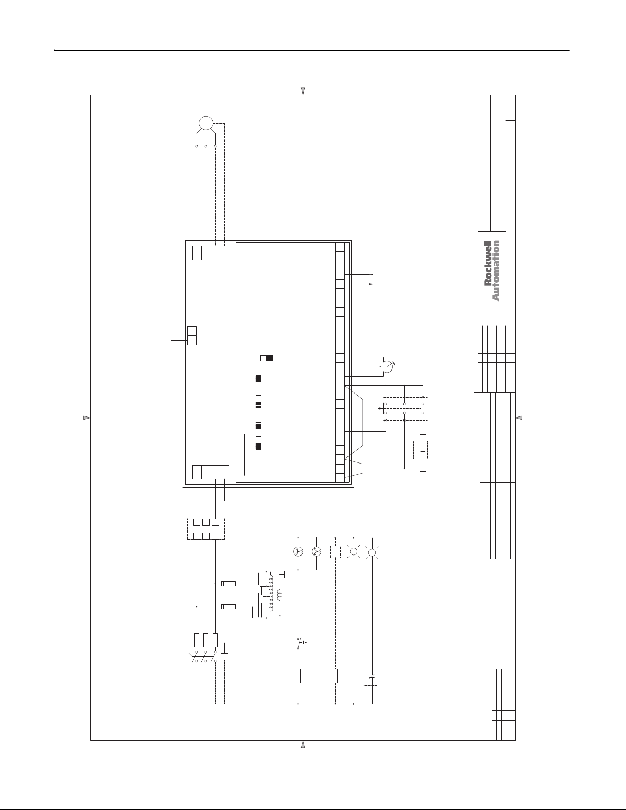
Figure 5 - 3.0…50 Hp, 208V AC & 3.0…150 Hp, 460V AC Drives - NEMA/UL Type 12 & 3R
98D01535
T3
T3
GND
#2 RELAY N.C.
PE
W/T3
POWERFLEX 400
PE
T/L3
CONTROL BOARD
AI2
10V 20MA
10V 20MA
10V 20MA10V 20MA
AO1 AO2 AI1
SRC
SNK
#2 RELAY COMMON
#2 RELAY N.O. (MOTOR RUNNING)
#1 RELAY N.C.
R3R120 R2 R5R4 R6
#1 RELAY COMMON
#1 RELAY N.O. (READY/FAULT)
RJ-45 SHIELD
OPTO OUTPUT (AT FREQUENCY)
19
ANALOG COM #2
ANALOG INPUT #2
ANALOG OUTPUT #2 (OUT CURRENT 0-10V)
ANALOG OUTPUT #1 (FREQUENCY 0-10V)
ANALOG COM. #1
ANALOG INPUT #1
+ 10VDC
+ 24VDC
OPTO COMMON
DIGITAL COMMON
DIGITAL INPUT 4 (COMM PORT)
DIGITAL INPUT 3 (CLEAR FAULT)
DIGITAL INPUT 2 (ANALOG 1 IN)
DIGITAL INPUT 1 (PURGE)
547698 1110 151312 14 1716 18
DIGITAL COMMON
SOFTWARE ENABLE
RUN/FWD
FUNCTION LOSS
123
SEE
3124
LADDER
12 13 14
11
AUTO
SS1
OFF
HAND
6
P1
SPEED
MANUAL
AUTO STA R T
34 35
434445
THIS DRAWING IS THE PROPERTY OF ROCKWELL AUTOMATION, INC.
OR ITS SUBSIDIARIES AND MAY NOT BE COPIED, USED OR DISCLOSED FOR ANY
PURPOSE EXCEPT AS AUTHORIZED IN WRITING BY ROCKWELL AUTOMATION, INC.
DATEREV. BY ECN/CR. NO.
A 2/17/06 JCL
B 8/3/06 JCL
TITLE
46
11
.SH.
SH.NEXT
NO
-
98D01535
NO.DATE DATE
DWG.ENG.
SCHEMATIC DRAWING - PF400, STYLE A, NEMA 3R, 12
3-50HP @ 208VAC, 3-150HP @ 460VAC
JFH/ACI
11/17/05
JCL/ACI
02/17/06
CHK. BY
11/17/05
DATE
DR. BY
C 11/14/06 REH
D 11/27/06 REH
E 12/15/06 JCL
F 6/7/07 REH
T
S
R
A2
C2C1
B2
LR
01
02030405060708
DS1
09
LINE
OPTIONAL
SWITCH
MAIN DISC.
OR OPTIONAL
10
REACTOR
CIRCUIT
A1
B1
L21
L23
L22
FU3
FU2
FU1
BREAKER
L1
11
G
L3
L2
f POWER
INCOMING
3
12131415161718
OPTIONAL
ONLY
ENCLOSURE
CF2
125, 150HP
HEATER
HTR
23
FU8
ENCLOSURE
FAN
X2
X2
CF1
X2
H4
T
X2
H3H2
460V
FU5
FU4
230V
208V
H1
192021
X1
31
115VAC
22
TH1
THERMOSTAT
21
FU7
22232425262728
LT1
POWER ON
G
31
29
LT2
24R3R2
FAULT
30
DRIVE FAULT
R
31
32333435363738
24 Rockwell Automation Publication 23C-IN001B-EN-P - June 2013
PARAMETER SETTING CHANGES
T073 ANALOG IN 2 SEL 2 "0-10V" 1 "4-20MA"
T052 DIGITAL IN2 SET 3 "LOCAL" 14 "ANLG 1 INCTRL"
A165 START AT POWERUP 0 "DISABLED" 1 "ENABLED"
P036 STA R T SOURCE 3 2-W LVL SENS" 6 2-W LVL SENS"
P038 SPEED REF 2 "ANALOG IN 1" 3 "ANALOG IN 2"
P042 AUTO MODE 1 "HND-OFF-AUTO" 0 "NO FUNCTION"
PARAMETER DESCRIPTION DEFAULT CHANGE TO
APPROVAL
AS SHIPPED
DESIGN REVIEW
AS COMMISSIONED
FOR MANUFACTURING
BYDATE
41
40
434445
39
42
46
Page 25
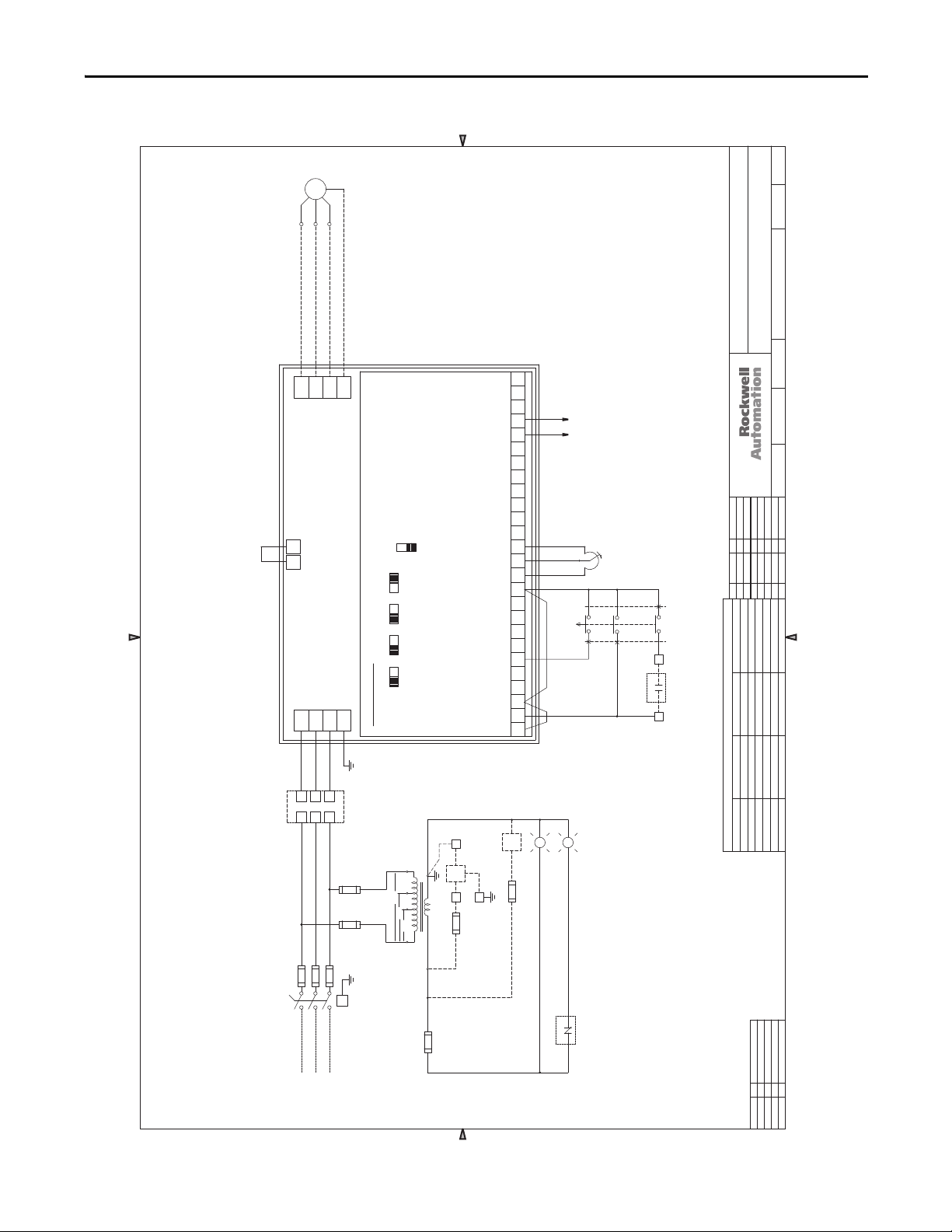
Figure 6 - 3.0…50 Hp, 208V AC & 3.0…100 Hp, 460V AC Drives - NEMA/UL Type 4
MOTOR
T2
T3
T2
T3
V/T2
POWERFLEX 400
S/L2
98D01537
GND
#2 RELAY N.C.
PE
W/T3
SRC
SNK
AI2
10V 20MA
10V 20MA
10V 20MA10V 20MA
AO1 AO2 AI1
CONTROL BOARD
PE
T/L3
#2 RELAY COMMON
#2 RELAY N.O. (MOTOR RUNNING)
#1 RELAY N.C.
R3R120 R2 R5R4 R6
#1 RELAY COMMON
#1 RELAY N.O. (READY/FAULT)
RJ-45 SHIELD
OPTO OUTPUT (AT FREQUENCY)
19
ANALOG COM #2
ANALOG INPUT #2
ANALOG OUTPUT #2 (OUT CURRENT 0-10V)
ANALOG OUTPUT #1 (FREQUENCY 0-10V)
ANALOG COM. #1
ANALOG INPUT #1
+ 10VDC
+ 24VDC
OPTO COMMON
DIGITAL COMMON
DIGITAL INPUT 4 (COMM PORT)
DIGITAL INPUT 3 (CLEAR FAULT)
DIGITAL INPUT 2 (ANALOG 1 IN)
DIGITAL INPUT 1 (PURGE)
DIGITAL COMMON
SOFTWARE ENABLE
RUN/FWD
FUNCTION LOSS
12 13 14
SS1
547698 1110 151312 14 1716 18
123
01
020304050607080910111213141516171819202122232425262728293031323334
T1
T1
U/T1
P1 P2
R/L1
Main Input Disconnect Package (Style A/M) Chapter 1
5
36373839404142
3124
3
SEE
LADDER
P1
SPEED
MANUAL
11
AUTO
OFF
HAND
6
18 AWG BLU
35
AUTO STA RT
34
434445
TITLE
THIS DRAWING IS THE PROPERTY OF ROCKWELL AUTOMATION, INC.
OR ITS SUBSIDIARIES AND MAY NOT BE COPIED, USED OR DISCLOSED FOR ANY
PURPOSE EXCEPT AS AUTHORIZED IN WRITING BY ROCKWELL AUTOMATION, INC.
DATEREV. BY ECN/CR. NO.
H 6/25/08 AWR
SCHEMATIC DRAWING - PF400, STYLE A, NEMA4
3 -50HP @ 208VAC & 3-100HP @ 460VAC
SH.NEXT
DWG.ENG.
JFH/ACI
JCL/ACI
CHK. BY
REH/ACI
DR. BY
46
11
.SH.
NO
-
98D01537
NO.DATE DATE
11/17/05
02/17/06
2/1/06
DATE
01
02030405060708
DS1
09
LINE
OPTIONAL
SWITCH
MAIN DISC.
OR OPTIONAL
10
REACTOR
CIRCUIT
T
S
R
A2
C2C1
B2
LR
A1
B1
L21
L23
L22
FU3
FU1
FU2
BREAKER
11
G
L1
L3
L2
f POWER
INCOMING
3
12131415161718
Rockwell Automation Publication 23C-IN001B-EN-P - June 2013 25
PARAMETER SETTING CHANGES
3-50HP@208VAC
7.5-100HP@460VAC
ENCLOSURE A/C
X2
WHT
X2
H4
T
A/C
X2
FU5
FU4
230V
208V
H1
192021
H3H2
460V
30
115VAC
FU7
RED
X1
FU6
SEE NOTE 1
31
22232425262728
OPTIONAL
ENCLOSURE
HTR
23
GRN
FU8
G
SEE NOTE 1
DRIVE FAULT
POWER ON
HEATER
T073 ANALOG IN 2 SEL 2 "0-10V" 1 "4-20MA"
T052 DIGITAL IN2 SET 3 "LOCAL" 14 "ANLG 1 INCTRL"
A165 START AT POWERUP 0 "DISABLED" 1 "ENABLED"
P036 STA R T SOURCE 3 2-W LVL SENS" 6 2-W LVL SENS"
P038 SPEED REF 2 "ANALOG IN 1" 3 "ANALOG IN 2"
P042 AUTO MODE 1 "HND-OFF-AUTO" 0 "NO FUNCTION"
G
R
LT1
LT2
31
24
R3R2
FAULT
NOTES:
1. NOT USED ON 3-5HP @ 460VAC.
31
30
29
32333435363738
39
PARAMETER DESCRIPTION DEFAULT CHANGE TO
APPROVAL
AS SHIPPED
DESIGN REVIEW
AS COMMISSIONED
FOR MANUFACTURING
BYDATE
41
40
42
434445
46
Page 26
Chapter 1 Main Input Disconnect Package (Style A/M)
01
0203040506070809101112131415161718192021222324252627282930313
MOTOR
T1
T3
T2
T1
T3
T2
GND
Figure 7 - 125…150 Hp, 460V AC Drives - NEMA/UL Type 4
98D01538
2
333435363738394041
42
434445
SH.NEXT
46
11
.SH.
NO
LINE
REACTOR
OPTIONAL
SCHEMATIC DRAWING - PF400, STYLE A, NEMA4
TITLE
OR ITS SUBSIDIARIES AND MAY NOT BE COPIED, USED OR DISCLOSED FOR ANY
PURPOSE EXCEPT AS AUTHORIZED IN WRITING BY ROCKWELL AUTOMATION, INC.
I 6/25/08 AWR
G 4/19/07 JCL
H12/31/07 JCL
-
98D01538
NO.DATE DATE
DWG.ENG.
125-150HP @ 460VAC
JFH/ACI
11/17/05
JCL/ACI
01/17/06
CHK. BY
JRF/ACI
11/17/05
DATE
DR. BY
#2 RELAY N.C.
V/T2
U/T1
W/T3
SRC
FU11
FU10
FU9
CONTROL BOARD
AI2
10V 20MA
10V 20MA
10V 20MA10V 20MA
AO1 AO2 AI1
L33
L32
L31
SNK
G
L3
43PE21
JP
AC1
L1 L2
X54
X40
P1 P2
POWERFLEX 400
T/L3
R/L1
S/L2
T
S
R
A2
C2C1
B2
LR
A1
B1
#2 RELAY COMMON
#2 RELAY N.O. (MOTOR RUNNING)
#1 RELAY N.C.
R3R120 R2 R5R4 R6
#1 RELAY COMMON
#1 RELAY N.O. (READY/FAULT)
RJ-45 SHIELD
OPTO OUTPUT (AT FREQUENCY)
19
ANALOG COM #2
ANALOG INPUT #2
ANALOG OUTPUT #2 (OUT CURRENT 0-10V)
ANALOG OUTPUT #1 (FREQUENCY 0-10V)
ANALOG COM. #1
ANALOG INPUT #1
+ 10VDC
+ 24VDC
OPTO COMMON
DIGITAL COMMON
DIGITAL INPUT 4 (COMM PORT)
DIGITAL INPUT 3 (CLEAR FAULT)
DIGITAL INPUT 2 (ANALOC 1 IN)
DIGITAL INPUT 1 (PURGE)
547698 1110 151312 14 1716 18
DIGITAL COMMON
SOFTWARE ENABLE
RUN/FWD
FUNCTION LOSS
123
SEE
LADDER
3124
12 13 14
11
AUTO
SS1
OFF
HAND
6
THIS DRAWING IS THE PROPERTY OF ROCKWELL AUTOMATION, INC.
P1
SPEED
MANUAL
35
DATEREV. BY ECN/CR. NO.
AUTO STA R T
34
PARAMETER SETTING CHANGES
L21
L23
01
02030405060708
OR
SWITCH
DS1-MAIN DISCONNECT
FU1
CIRCUIT
BREAKER
CB1-OPTIONAL
L1
09
L22
FU2
L2
f POWER
INCOMING
3
10
FU3
L3
FU5
FU4
LG
11
12131415161718
192021
460V
230V
208V
22232425262728
OPTIONAL
POWER ON
ENCLOSURE
HEATER
X2
HTR
H4
T
X2
H3H2
H1
23
115VAC
X1
FU8
31
DRIVE FAULT
G
R
LT1
LT2
31
R3
FAULT
R2 24
31
30
29
32333435363738
26 Rockwell Automation Publication 23C-IN001B-EN-P - June 2013
T073 ANALOG IN 2 SEL 2 "0-10V" 1 "4-20MA"
T052 DIGITAL IN2 SET 3 "LOCAL" 14 "ANLG 1 INCTRL"
A165 START AT POWERUP 0 "DISABLED" 1 "ENABLED"
P036 STA R T SOURCE 3 2-W LVL SENS" 6 2-W LVL SENS"
P038 SPEED REF 2 "ANALOG IN 1" 3 "ANALOG IN 2"
P042 AUTO MODE 1 "HND-OFF-AUTO" 0 "NO FUNCTION"
PARAMETER DESCRIPTION DEFAULT CHANGE TO
APPROVAL
AS SHIPPED
DESIGN REVIEW
AS COMMISSIONED
FOR MANUFACTURING
BYDATE
41
40
39
42
434445
46
Page 27

Interconnect Drawings
0203040506070809101112131415161718192021222324252627282930313233343536373839404142
01
Main Input Disconnect Package (Style A/M) Chapter 1
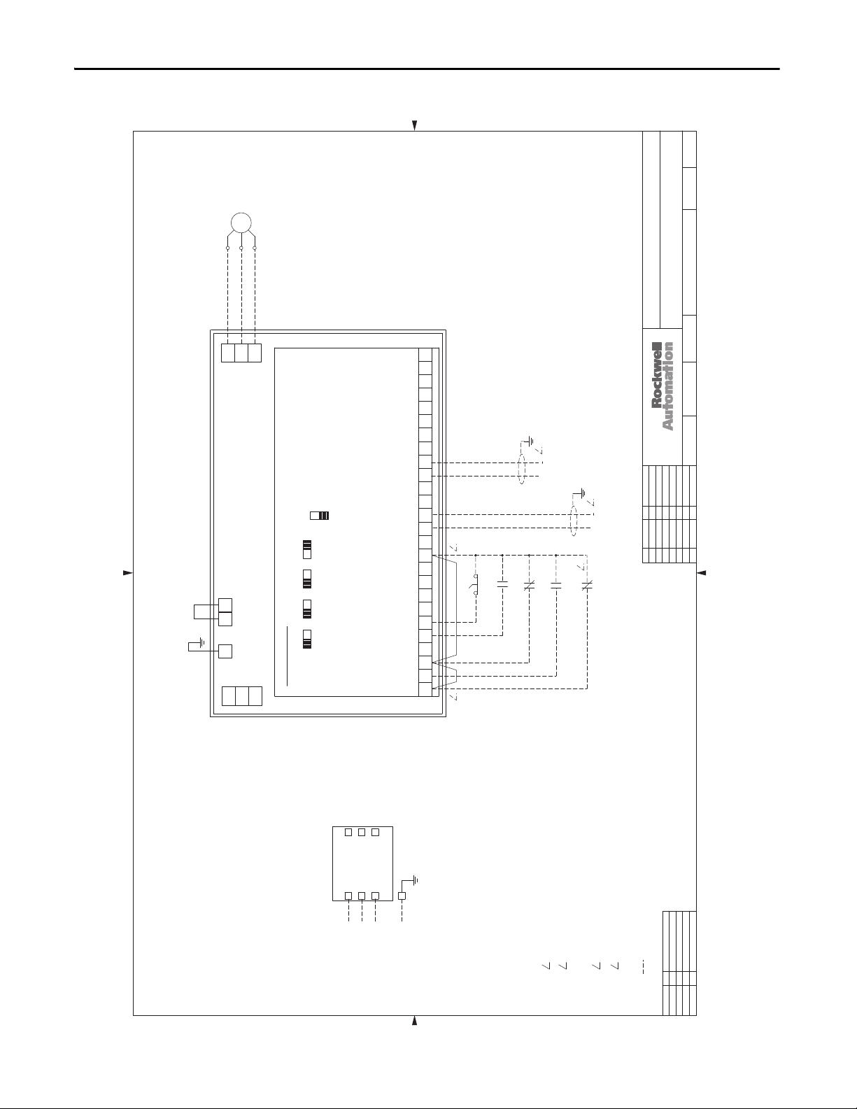
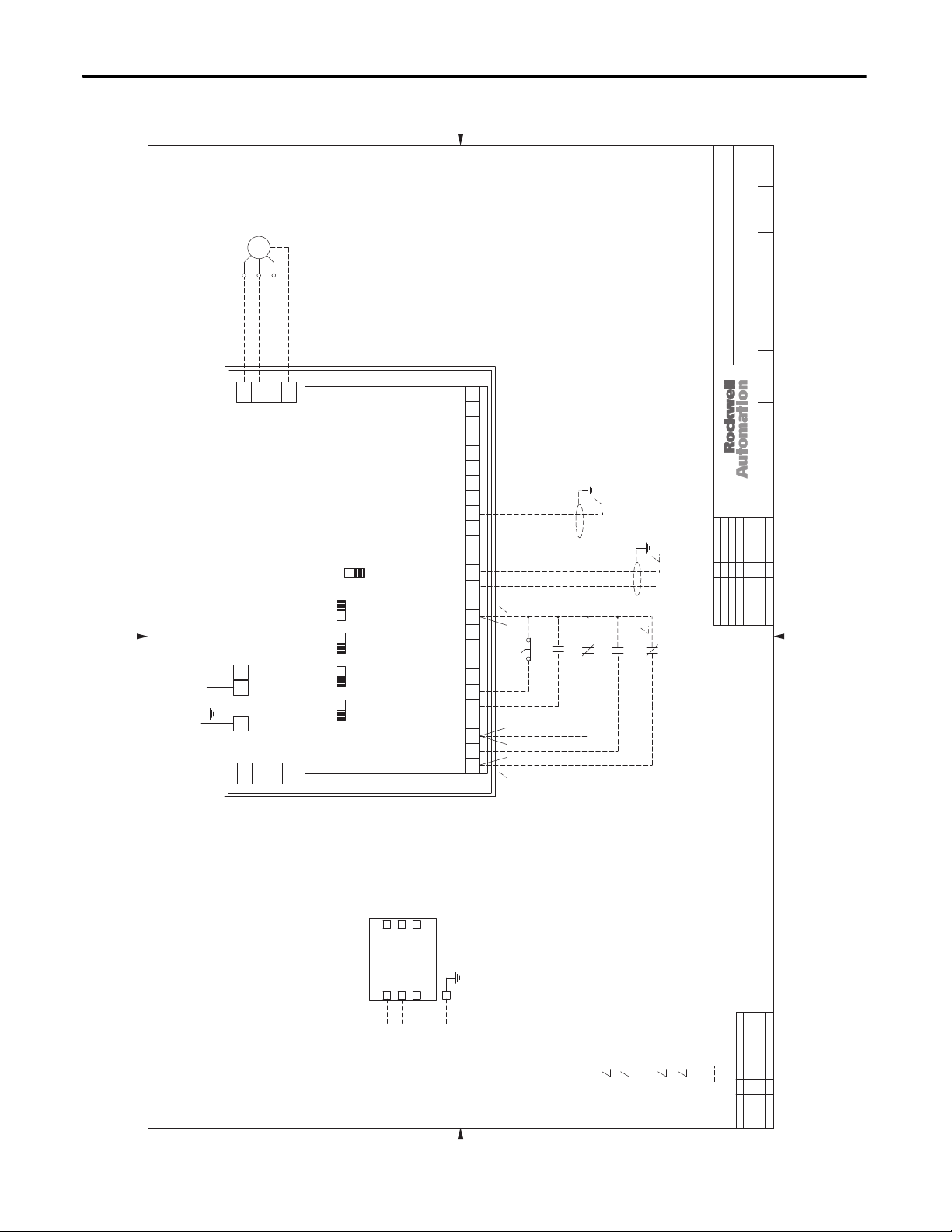
Figure 8 - 3.0…50 Hp, 208V AC & 3.0…150 Hp, 460V AC Drives - NEMA/UL Type 1
97D00696
SH.NEXT
11
NO.SH.
MOTOR
T1
T2
V/T2
U/T1
POWERFLEX 400
G P2P1
R/L1
S/L2
T3
W/T3
T/L3
G
-
97D00696
NO.DATE DATE
DWG.ENG.
INTER-CONNECT DRAWING - PF400, STYLE A
3-50HP @ 208VAC & 3-150HP @ 460VAC
TITLE
THIS DRAWING IS THE PROPERTY OF ROCKWELL AUTOMATION, INC.
OR ITS SUBSIDIARIES AND MAY NOT BE COPIED, USED OR DISCLOSED FOR ANY
PURPOSE EXCEPT AS AUTHORIZED IN WRITING BY ROCKWELL AUTOMATION, INC.
G
DM1
AI2
10V 20MA10V 20MA
AI1
10V 20MA
AO1 AO2
10V 20MA
SRC
SNK
CONTROL BOARD
#2 RELAY N.C.
#2 RELAY COMMON
#2 RELAY N.O. (MOTOR RUNNING)
#1 RELAY N.C.
#1 RELAY COMMON
#1 RELAY N.O. (READY/FAULT)
R1
RJ-45 SHIELD
OPTO OUTPUT (AT FREQUENCY)
ANALOG COM #2
ANALOG INPUT #2
ANALOG OUTPUT #2 (OUTPUT CURRENT 0-10V)
ANALOG OUTPUT #1 (FREQUENCY 0-10V)
ANALOG COM. #1
ANALOG INPUT #1
+ 10VDC
+ 24VDC
11 12 1413 15 1716 18 2019 R4R2 R3 R5 R6
OPTO COMMON
10
DIGITAL COMMON
DIGITAL INPUT 4 (COMM PORT)
DIGITAL INPUT 3 (CLEAR FAULT)
DIGITAL INPUT 2 (LOCAL)
DIGITAL INPUT 1 (PURGE)
DIGITAL COMMON
SOFTWARE ENABLE
RUN/FWD
FUNCTION LOSS
AUTO
HAND
576 89
324
1
3 4
PURGE
2
INTERLOCKS
+
SPEED REF. INPUT
4-20MA, 250 OHM
AUTO START
INPUT IMPEDANCE
STAT S
FREEZE/FIRE
JFH/ACI
4/5/04
CHK. BY
JRF/ACI
4/5/04
DATE
DR. BY
2
+
SPEED REF. INPUT
1
0 TO +10VDC, 100KOHM
INPUT IMPEDANCE
DATEREV. BY ECN/CR. NO.
A 11/24/04 JRF
B 2/3/05 JRF
C 11/14/06 REH
D 2/2/11 DJK
01
02030405060708
DS1
MAIN
SWITCH
DISCONNECT
L1
INCOMING
G
L3
L2
GROUND
f POWER
3
11
10
09
12131415161718
192021
22232425262728
31
30
29
OPENING OF THE FREEZE/FIRE INTERLOCK
1
WHEN IN "AUTO MODE" SPEED REFERENCE WILL
COME FROM 0-10V SOURCE WIRED TO ANALOG
INPUT #1. IF 4-20mA SOURCE IS TO BE USED,
WIRE TO ANALOG INPUT #2 AND CHANGE PARAMETER
PO38 [SPEED REFERENCE] =3 "ANALOG In2".
IF THE INTERLOCK CONTACT IS USED, THE JUMPER
IF FREEZE/FIRE STAUS INTERLOCK IS USED, THE
WILL REQUIRE MANUAL RESET.
32333435363738
JUMPER WIRE FROM TERMINALS 1 TO 3 MUST BE REMOVED.
2
3
FROM TERMINALS 1 TO 3 MUST BE REMOVED AND
THE JUMPER WIRE FROM TERMINALS 3 TO 11 SHOULD4BE RELOCATED TO CONNECT TERMINALS 1 TO 11.
CONNECTIONS SUPPLIED BY CUSTOMER
39
APPROVAL
DESIGN REVIEW
FOR MANUFACTURING
BYDATE
41
40
AS SHIPPED
AS COMMISSIONED
42
Rockwell Automation Publication 23C-IN001B-EN-P - June 2013 27
Page 28
Chapter 1 Main Input Disconnect Package (Style A/M)
01
02030405060708
09
10
11
12131415161718
192021
30
31
40
41
0203040506070809101112131415161718192021222324252627282930313233343536373839404142
01
DATEREV. BY ECN/CR. NO.
A 11/24/04 JRF
B 4/21/08 TGM
C 6/25/08 AWR
D 2/2/11 DJK
APPROVAL
DESIGN REVIEW
FOR MANUFACTURING
AS SHIPPED
AS COMMISSIONED
BYDATE
SH.NEXT
NO.SH.
-
DWG.ENG.
TITLE
CHK. BY
NO.DATE DATE
DR. BY
DATE
THIS DRAWING IS THE PROPERTY OF ROCKWELL AUTOMATION, INC.
OR ITS SUBSIDIARIES AND MAY NOT BE COPIED, USED OR DISCLOSED FOR ANY
PURPOSE EXCEPT AS AUTHORIZED IN WRITING BY ROCKWELL AUTOMATION, INC.
11
INTER-CONNECT DRAWING - PF400, STYLE A, W/LINE REACTOR
3-50HP @ 208VAC & 3-150HP @ 460VAC
97D00754
JRF/ACI
5/17/04
JFH/ACI
5/17/04
11/24/04
G
L3
INCOMING
3
f POWER
L2
L1
MAIN
DISCONNECT
SWITCH
GROUND
CONNECTIONS SUPPLIED BY CUSTOMER
OPENING OF THE FREEZE/FIRE INTERLOCK
WILL REQUIRE MANUAL RESET.
1
10
OPTO COMMON
AUTO
DIGITAL INPUT 4 (COMM PORT)
DIGITAL COMMON
DIGITAL INPUT 3 (CLEAR FAULT)
DIGITAL INPUT 2 (LOCAL)
DIGITAL COMMON
DIGITAL INPUT 1 (PURGE)
SOFTWARE ENABLE
FUNCTION LOSS
STAT S
FREEZE/FIRE
AUTO START
INTERLOCKS
1
RUN/FWD
324
PURGE
HAND
576 89
10V 20MA
AO1 AO2
10V 20MA
CONTROL BOARD
S/L2
T/L3
R/L1
G P2P1
RJ-45 SHIELD
#2 RELAY N.C.
#2 RELAY COMMON
#2 RELAY N.O. (MOTOR RUNNING)
#1 RELAY N.C.
#1 RELAY COMMON
OPTO OUTPUT (AT FREQUENCY)
ANALOG COM #2
#1 RELAY N.O. (READY/FAULT)
ANALOG INPUT #2
ANALOG OUTPUT #2 (OUTPUT CURRENT 0-10V)
ANALOG OUTPUT #1 (FREQUENCY 0-10V)
ANALOG COM. #1
ANALOG INPUT #1
SPEED REF. INPUT
0 TO +10VDC, 100KOHM
INPUT IMPEDANCE
R1
1
+
SPEED REF. INPUT
4-20MA, 250 OHM
INPUT IMPEDANCE
+
+ 24VDC
+ 10VDC
11 12 1413 15 1716 18 2019 R4R2 R3 R5 R6
10V 20MA10V 20MA
AI1
SNK
AI2
SRC
POWERFLEX 400
W/T3
V/T2
U/T1
MOTOR
T2
T3
T1
2
2
2
WHEN IN "AUTO MODE" SPEED REFERENCE WILL
COME FROM 0-10V SOURCE WIRED TO ANALOG
INPUT #1. IF 4-20mA SOURCE IS TO BE USED,
WIRE TO ANALOG INPUT #2 AND CHANGE PARAMETER
PO38 [SPEED REFERENCE] =3 "ANALOG In2".
DM1
DS1
3 4
IF FREEZE/FIRE STAUS INTERLOCK IS USED, THE
JUMPER WIRE FROM TERMINALS 1 TO 3 MUST BE REMOVED.
3
IF THE INTERLOCK CONTACT IS USED, THE JUMPER
FROM TERMINALS 1 TO 3 MUST BE REMOVED AND
THE JUMPER WIRE FROM TERMINALS 3 TO 11 SHOULD4BE RELOCATED TO CONNECT TERMINALS 1 TO 11.
Figure 9 - 3.0…50 Hp, 208V AC & 3.0…150 Hp, 460V AC Drives with Line Reactor - NEMA/UL Type 1
97D00754
28 Rockwell Automation Publication 23C-IN001B-EN-P - June 2013
Page 29

Figure 10 - 200 Hp, 460V AC Drives - NEMA/UL Type 1
01
02030405060708
09
10
11
12131415161718
192021
30
31
40
41
0203040506070809101112131415161718192021222324252627282930313233343536373839404142
01
DATEREV. BY ECN/CR. NO.
A 4/11/12 JCK
APPROVAL
DESIGN REVIEW
FOR MANUFACTURING
AS SHIPPED
AS COMMISSIONED
BYDATE
SH.NEXT
NO.SH.
-
DWG.ENG.
TITLE
CHK. BY
NO.DATE DATE
DR. BY
DATE
THIS DRAWING IS THE PROPERTY OF ROCKWELL AUTOMATION, INC.
OR ITS SUBSIDIARIES AND MAY NOT BE COPIED, USED OR DISCLOSED FOR ANY
PURPOSE EXCEPT AS AUTHORIZED IN WRITING BY ROCKWELL AUTOMATION, INC.
11
INTER-CONNECT DRAWING (DISCONNECT SWITCH)
PF400, 200HP/460VAC, NEMA1
STYLE A, FRAME G, CONTROL
97D01890
REH/ACI
10/9/06
AWR/ACI
10/9/06
AWR/ACI
10/9/06
G
L3
INCOMING
3
f POWER
L2
L1
MAIN
DISCONNECT
SWITCH
GROUND
CONNECTIONS SUPPLIED BY CUSTOMER
OPENING OF THE FREEZE/FIRE INTERLOCK
WILL REQUIRE MANUAL RESET.
1
10
OPTO COMMON
AUTO
DIGITAL INPUT 4 (COMM PORT)
DIGITAL COMMON
DIGITAL INPUT 3 (CLEAR FAULT)
DIGITAL INPUT 2 (LOCAL)
DIGITAL COMMON
DIGITAL INPUT 1 (PURGE)
SOFTWARE ENABLE
FUNCTION LOSS
STAT S
FREEZE/FIRE
AUTO START
INTERLOCKS
1
RUN/FWD
324
PURGE
HAND
576 89
10V 20MA
AO1 AO2
10V 20MA
CONTROL BOARD
S/L2
T/L3
R/L1
G P2P1
RJ-45 SHIELD
#2 RELAY N.C.
#2 RELAY COMMON
#2 RELAY N.O. (MOTOR RUNNING)
#1 RELAY N.C.
#1 RELAY COMMON
OPTO OUTPUT (AT FREQUENCY)
ANALOG COM #2
#1 RELAY N.O. (READY/FAULT)
ANALOG INPUT #2
ANALOG OUTPUT #2 (OUTPUT CURRENT 0-10V)
ANALOG OUTPUT #1 (FREQUENCY 0-10V)
ANALOG COM. #1
ANALOG INPUT #1
SPEED REF. INPUT
0 TO +10VDC, 100KOHM
INPUT IMPEDANCE
R1
1
+
SPEED REF. INPUT
4-20MA, 250 OHM
INPUT IMPEDANCE
+
+ 24VDC
+ 10VDC
11 12 1413 15 1716 18 2019 R4R2 R3 R5 R6
10V 20MA10V 20MA
AI1
SNK
AI2
SRC
POWERFLEX 400
W/T3
V/T2
U/T1
MOTOR
T2
T3
T1
2
2
2
WHEN IN "AUTO MODE" SPEED REFERENCE WILL
COME FROM 0-10V SOURCE WIRED TO ANALOG
INPUT #1. IF 4-20mA SOURCE IS TO BE USED,
WIRE TO ANALOG INPUT #2 AND CHANGE PARAMETER
PO38 [SPEED REFERENCE] =3 "ANALOG In2".
DM1
DS1
3 4
IF FREEZE/FIRE STAUS INTERLOCK IS USED, THE
JUMPER WIRE FROM TERMINALS 1 TO 3 MUST BE REMOVED.
3
IF THE INTERLOCK CONTACT IS USED, THE JUMPER
FROM TERMINALS 1 TO 3 MUST BE REMOVED AND
THE JUMPER WIRE FROM TERMINALS 3 TO 11 SHOULD4BE RELOCATED TO CONNECT TERMINALS 1 TO 11.
PE
97D01890
Main Input Disconnect Package (Style A/M) Chapter 1
Rockwell Automation Publication 23C-IN001B-EN-P - June 2013 29
Page 30
Chapter 1 Main Input Disconnect Package (Style A/M)
01
02030405060708
09
10
11
12131415161718
192021
30
31
40
41
0203040506070809101112131415161718192021222324252627282930313233343536373839404142
01
DATEREV. BY ECN/CR. NO.
A 4/11/12 JCK
APPROVAL
DESIGN REVIEW
FOR MANUFACTURING
AS SHIPPED
AS COMMISSIONED
BYDATE
SH.NEXT
NO.SH.
-
DWG.ENG.
TITLE
CHK. BY
NO.DATE DATE
DR. BY
DATE
THIS DRAWING IS THE PROPERTY OF ROCKWELL AUTOMATION, INC.
OR ITS SUBSIDIARIES AND MAY NOT BE COPIED, USED OR DISCLOSED FOR ANY
PURPOSE EXCEPT AS AUTHORIZED IN WRITING BY ROCKWELL AUTOMATION, INC.
11
INTER-CONNECT DRAWING (CIRCUIT BREAKER)
PF400, 250-350HP/460VAC, NEMA1
STYLE A, FRAMES G & H, CONTROL
97D01889
REH/ACI
10/9/06
AWR/ACI
10/9/06
AWR/ACI
10/9/06
G
L3
INCOMING
3
f POWER
L2
L1
MAIN
CIRCUIT
BREAKER
GROUND
CONNECTIONS SUPPLIED BY CUSTOMER
OPENING OF THE FREEZE/FIRE INTERLOCK
WILL REQUIRE MANUAL RESET.
1
10
OPTO COMMON
AUTO
DIGITAL INPUT 4 (COMM PORT)
DIGITAL COMMON
DIGITAL INPUT 3 (CLEAR FAULT)
DIGITAL INPUT 2 (LOCAL)
DIGITAL COMMON
DIGITAL INPUT 1 (PURGE)
SOFTWARE ENABLE
FUNCTION LOSS
STAT S
FREEZE/FIRE
AUTO START
INTERLOCKS
1
RUN/FWD
324
PURGE
HAND
576 89
10V 20MA
AO1 AO2
10V 20MA
CONTROL BOARD
S/L2
T/L3
R/L1
G P2P1
RJ-45 SHIELD
#2 RELAY N.C.
#2 RELAY COMMON
#2 RELAY N.O. (MOTOR RUNNING)
#1 RELAY N.C.
#1 RELAY COMMON
OPTO OUTPUT (AT FREQUENCY)
ANALOG COM #2
#1 RELAY N.O. (READY/FAULT)
ANALOG INPUT #2
ANALOG OUTPUT #2 (OUTPUT CURRENT 0-10V)
ANALOG OUTPUT #1 (FREQUENCY 0-10V)
ANALOG COM. #1
ANALOG INPUT #1
SPEED REF. INPUT
0 TO +10VDC, 100KOHM
INPUT IMPEDANCE
R1
1
+
SPEED REF. INPUT
4-20MA, 250 OHM
INPUT IMPEDANCE
+
+ 24VDC
+ 10VDC
11 12 1413 15 1716 18 2019 R4R2 R3 R5 R6
10V 20MA10V 20MA
AI1
SNK
AI2
SRC
POWERFLEX 400
W/T3
V/T2
U/T1
MOTOR
T2
T3
T1
2
2
2
WHEN IN "AUTO MODE" SPEED REFERENCE WILL
COME FROM 0-10V SOURCE WIRED TO ANALOG
INPUT #1. IF 4-20mA SOURCE IS TO BE USED,
WIRE TO ANALOG INPUT #2 AND CHANGE PARAMETER
PO38 [SPEED REFERENCE] =3 "ANALOG In2".
DM1
CB1
3 4
IF FREEZE/FIRE STAUS INTERLOCK IS USED, THE
JUMPER WIRE FROM TERMINALS 1 TO 3 MUST BE REMOVED.
3
IF THE INTERLOCK CONTACT IS USED, THE JUMPER
FROM TERMINALS 1 TO 3 MUST BE REMOVED AND
THE JUMPER WIRE FROM TERMINALS 3 TO 11 SHOULD4BE RELOCATED TO CONNECT TERMINALS 1 TO 11.
PE
Figure 11 - 250…350 Hp, 460V AC Drives - NEMA/UL Type 1
97D01889
30 Rockwell Automation Publication 23C-IN001B-EN-P - June 2013
Page 31

Figure 12 - 3.0…50 Hp, 208V AC & 3.0…150 Hp, 460V AC Drives - NEMA/UL Type 12, 4, & 3R
01
02030405060708
09
10
11
12131415161718
192021
30
31
40
41
0203040506070809101112131415161718192021222324252627282930313233343536373839404142
01
DATEREV. BY ECN/CR. NO.
A 11/14/06 REH
B 4/11/12 JCK
APPROVAL
DESIGN REVIEW
FOR MANUFACTURING
AS SHIPPED
AS COMMISSIONED
BYDATE
SH.NEXT
NO.SH.
-
DWG.ENG.
TITLE
CHK. BY
NO.DATE DATE
DR. BY
DATE
THIS DRAWING IS THE PROPERTY OF ROCKWELL AUTOMATION, INC.
OR ITS SUBSIDIARIES AND MAY NOT BE COPIED, USED OR DISCLOSED FOR ANY
PURPOSE EXCEPT AS AUTHORIZED IN WRITING BY ROCKWELL AUTOMATION, INC.
11
INTER-CONNECT DRAWING - PF400, STYLE A
3-50HP @ 208VAC, 3-150HP @ 460VAC
NEMA 3R, 4, 12
97D01548
JFH/ACI
11/23/05
JCL/ACI
02/17/06
JFH/ACI
11/23/06
INCOMING
3
f POWER
MAIN
DISCONNECT
SWITCH
GROUND
CONNECTIONS SUPPLIED BY CUSTOMER
OPENING OF THE FREEZE/FIRE INTERLOCK
WILL REQUIRE MANUAL RESET.
1
10
OPTO COMMON
AUTO
DIGITAL INPUT 4 (COMM PORT)
DIGITAL COMMON
DIGITAL INPUT 3 (CLEAR FAULT)
DIGITAL INPUT 2 (ANALOG 1 IN)
DIGITAL COMMON
DIGITAL INPUT 1 (PURGE)
SOFTWARE ENABLE
FUNCTION LOSS
STAT S
FREEZE/FIRE
AUTO START
INTERLOCKS
1
RUN/FWD
324
PURGE
HAND
576 89
10V 20MA
AO1 AO2
10V 20MA
CONTROL BOARD
S/L2
T/L3
R/L1
P2P1
RJ-45 SHIELD
#2 RELAY N.C.
#2 RELAY COMMON
#2 RELAY N.O. (MOTOR RUNNING)
#1 RELAY N.C.
#1 RELAY COMMON
OPTO OUTPUT (AT FREQUENCY)
ANALOG COM #2
#1 RELAY N.O. (READY/FAULT)
ANALOG INPUT #2
ANALOG OUTPUT #2 (OUTPUT CURRENT 0-10V)
ANALOG OUTPUT #1 (FREQUENCY 0-10V)
ANALOG COM. #1
ANALOG INPUT #1
R1
1
SPEED REF. INPUT
4-20MA, 250 OHM
INPUT IMPEDANCE
+
+ 24VDC
+ 10VDC
11 12 1413 15 1716 18 2019 R4R2 R3 R5 R6
10V 20MA10V 20MA
AI1
SNK
AI2
SRC
POWERFLEX 400
W/T3
V/T2
U/T1
2
2
WHEN IN "AUTO MODE" SPEED REFERENCE WILL
COME FROM 4-20ma SOURCE WIRED TO ANALOG
INPUT #2. IF 0-10V SOURCE IS TO BE USED,
CHANGE PARAMETER T73 TO "2" VOLTAGE MODE AND
SET DIP SWITCH "AI2" TO 10V.
DM1
DS1orCB1
3 4
IF FREEZE/FIRE STAUS INTERLOCK IS USED, THE
JUMPER WIRE FROM TERMINALS 1 TO 3 MUST BE REMOVED.
3
IF THE INTERLOCK CONTACT IS USED, THE JUMPER
FROM TERMINALS 1 TO 3 MUST BE REMOVED AND
THE JUMPER WIRE FROM TERMINALS 3 TO 11 SHOULD4BE RELOCATED TO CONNECT TERMINALS 1 TO 11.
34 35
CUSTOMER CONNECTIONS
AUTO START
T3 T2 T1
MOTOR
TB
34 35
OFF
XXX
L3L2L1GND
PE
97D01548
Main Input Disconnect Package (Style A/M) Chapter 1
Rockwell Automation Publication 23C-IN001B-EN-P - June 2013 31
Page 32

Chapter 1 Main Input Disconnect Package (Style A/M)
Layout Drawings
0203040506070809101112131415161718192021222324252627282930313233343536373839404142
01
Figure 13 - 3.0…10 Hp, 208V AC & 3.0…20 Hp, 460V AC Drives - NEMA/UL Type 1
95D00758
CONTROL COMPONENT AND TERMINAL BLOCK LOCATIONS
PF400, FRAME C, STYLE A, 1 - 20HP @ 460VAC
PF400, FRAME C, STYLE A, 1 - 10HP @ 208VAC
TITLE
THIS DRAWING IS THE PROPERTY OF ROCKWELL AUTOMATION, INC.
OR ITS SUBSIDIARIES AND MAY NOT BE COPIED, USED OR DISCLOSED FOR ANY
PURPOSE EXCEPT AS AUTHORIZED IN WRITING BY ROCKWELL AUTOMATION, INC.
(20HP @ 460VAC SHOWN)
11
SH.NEXT
NO.SH.
-
95D00758
NO.DATE DATE
DWG.ENG.
JFH/ACI
5/17/04
CHK. BY
JRF/ACI
5/17/04
DATE
DR. BY
TERMINAL BLOCK
SIGNAL
TERMINAL BLOCK
POWER
400
DS1
INPUT POWER
TERMINAL BLOCK
FU1
FU2
FU3
178358-02
USC
L
U
LISTED
INDUSTRIAL CONTROL EQUIPMENT 38MN
DATEREV. BY ECN/CR. NO.
A 6/2/04 JRF
B 11/24/04 JRF
C 2/2/11 DJK
D 4/2/12 JCK
L1
L2L3
PE GROUND
GND
APPROVAL
AS SHIPPED
DESIGN REVIEW
AS COMMISSIONED
FOR MANUFACTURING
BYDATE
11
01
02030405060708
10
09
12131415161718
192021
22232425262728
30
29
32 Rockwell Automation Publication 23C-IN001B-EN-P - June 2013
31
32333435363738
41
40
39
42
Page 33

Main Input Disconnect Package (Style A/M) Chapter 1
Figure 14 - 15…20 Hp, 208V AC & 25…40 Hp, 460V AC Drives - NEMA/UL Type 1
0203040506070809101112131415161718192021222324252627282930313233343536373839404142
01
95D00759
(40HP @ 460VAC SHOWN)
THIS DRAWING IS THE PROPERTY OF ROCKWELL AUTOMATION, INC.
OR ITS SUBSIDIARIES AND MAY NOT BE COPIED, USED OR DISCLOSED FOR ANY
11
SH.NEXT
NO.SH.
-
95D00759
NO.DATE DATE
DWG.ENG.
CONTROL COMPONENT AND TERMINAL BLOCK LOCATIONS
PF400, FRAME D, STYLE A, 25-40HP @ 460VAC
PF400, FRAME D, STYLE A, 15-20HP @ 208VAC
TITLE
PURPOSE EXCEPT AS AUTHORIZED IN WRITING BY ROCKWELL AUTOMATION, INC.
JFH/ACI
5/18/04
CHK. BY
JRF/ACI
5/18/04
DATE
DR. BY
SIGNAL
TERMINAL BLOCK
POWER
TERMINAL BLOCK
INPUT POWER
TERMINAL BLOCK
ON
DS1
FU1
FU2
FU3
PE GROUND
OFF
ALLEN-BRADLEY 194R-NJ100P3
GND
L3 L2 L1
DATEREV. BY ECN/CR. NO.
178358-02
US
L
U
LISTED
C
INDUSTRIAL CONTROL EQUIPMENT 38MN
ACTURING
APPROVAL
AS SHIPPED
DESIGN REVIEW
AS COMMISSIONED
FOR MANUF
BYDATE
01
02030405060708
11
10
09
12131415161718
192021
22232425262728
31
30
29
32333435363738
41
40
39
42
Rockwell Automation Publication 23C-IN001B-EN-P - June 2013 33
Page 34

Chapter 1 Main Input Disconnect Package (Style A/M)
0203040506070809101112131415161718192021222324252627282930313233343536373839404142
01
Figure 15 - 25…30 Hp, 208V AC Drives - NEMA/UL Type 1
95D00775
(30HP SHOWN)
THIS DRAWING IS THE PROPERTY OF ROCKWELL AUTOMATION, INC.
OR ITS SUBSIDIARIES AND MAY NOT BE COPIED, USED OR DISCLOSED FOR ANY
PURPOSE EXCEPT AS AUTHORIZED IN WRITING BY ROCKWELL AUTOMATION, INC.
TITLE
CONTROL COMPONENT AND TERMINAL BLOCK LOCATIONS
PF400, FRAME D, STYLE A, 25-30HP @ 208VAC
11
SH.NEXT
NO.SH.
-
95D00775
NO.DATE DATE
DWG.ENG.
JFH/ACI
5/18/04
CHK. BY
JRF/ACI
5/18/04
DATE
DR. BY
SIGNAL
TERMINAL BLOCK
TERMINAL BLOCK
POWER
DATEREV. BY ECN/CR. NO.
INPUT POWER
TERMINAL BLOCK
ON
OFF
FU1
DS1
FU2
FU3
L3 L1L2
PE GROUND
GND
178358-02
US
L
U
LISTED
C
INDUSTRIAL CONTROL EQUIPMENT 38MN
ACTURING
APPROVAL
AS SHIPPED
DESIGN REVIEW
AS COMMISSIONED
FOR MANUF
BYDATE
01
02030405060708
11
10
09
12131415161718
192021
22232425262728
30
29
34 Rockwell Automation Publication 23C-IN001B-EN-P - June 2013
31
32333435363738
41
40
39
42
Page 35

Main Input Disconnect Package (Style A/M) Chapter 1
Figure 16 - 40 Hp, 208V AC & 50…100 Hp, 460V AC Drives - NEMA/UL Type 1
0203040506070809101112131415161718192021222324252627282930313233343536373839404142
01
95D00760
(100HP @ 460VAC SHOWN)
THIS DRAWING IS THE PROPERTY OF ROCKWELL AUTOMATION, INC.
OR ITS SUBSIDIARIES AND MAY NOT BE COPIED, USED OR DISCLOSED FOR ANY
11
SH.NEXT
NO.SH.
-
95D00760
NO.DATE DATE
DWG.ENG.
CONTROL COMPONENT AND TERMINAL BLOCK LOCATIONS
PF400, FRAME E, STYLE A, 50-100HP @ 460VAC
PF400, FRAME E, STYLE A, 40HP @ 208VAC
TITLE
PURPOSE EXCEPT AS AUTHORIZED IN WRITING BY ROCKWELL AUTOMATION, INC.
JFH/ACI
5/18/04
CHK. BY
JRF/ACI
5/18/04
DATE
DR. BY
DATEREV. BY ECN/CR. NO.
SIGNAL
TERMINAL BLOCK
PORT
MOD
NET A
NET B
TERMINAL BLOCK
POWER
INPUT POWER
TERMINAL BLOCK
ON
OFF
FU1
DS1
FU2
FU3
L3 L1L2
PE GROUND
GND
178358-02
US
L
U
LISTED
C
INDUSTRIAL CONTROL EQUIPMENT 38MN
ACTURING
APPROVAL
AS SHIPPED
DESIGN REVIEW
AS COMMISSIONED
FOR MANUF
BYDATE
01
02030405060708
11
10
09
12131415161718
192021
22232425262728
31
30
29
32333435363738
41
40
39
42
Rockwell Automation Publication 23C-IN001B-EN-P - June 2013 35
Page 36

Chapter 1 Main Input Disconnect Package (Style A/M)
0203040506070809101112131415161718192021222324252627282930313233343536373839404142
01
Figure 17 - 50 Hp, 208V AC Drives - NEMA/UL Type 1
95D00776
THIS DRAWING IS THE PROPERTY OF ROCKWELL AUTOMATION, INC.
OR ITS SUBSIDIARIES AND MAY NOT BE COPIED, USED OR DISCLOSED FOR ANY
PURPOSE EXCEPT AS AUTHORIZED IN WRITING BY ROCKWELL AUTOMATION, INC.
TITLE
CONTROL COMPONENT AND TERMINAL BLOCK LOCATIONS
PF400, FRAME E, STYLE A, 50HP @ 208VAC
11
SH.NEXT
NO.SH.
-
95D00776
NO.DATE DATE
DWG.ENG.
JFH/ACI
5/27/04
CHK. BY
JRF/ACI
5/27/04
DATE
DR. BY
INPUT POWER
TERMINAL BLOCK
PE GROUND
DS1
DATEREV. BY ECN/CR. NO.
GND
ON
OFF
FU3
FU2
L1 L2 L3
FU1
PORT
MOD
NET A
NET B
POWER
TERMINAL BLOCK
22232425262728
30
29
01
02030405060708
11
10
09
12131415161718
TERMINAL BLOCK
SIGNAL
192021
36 Rockwell Automation Publication 23C-IN001B-EN-P - June 2013
31
32333435363738
ACTURING
APPROVAL
AS SHIPPED
DESIGN REVIEW
AS COMMISSIONED
FOR MANUF
BYDATE
41
40
39
42
Page 37

Main Input Disconnect Package (Style A/M) Chapter 1
Figure 18 - 125…150 Hp, 460V AC Drives - NEMA/UL Type 1
0203040506070809101112131415161718192021222324252627282930313233343536373839404142
01
PE GROUND
INPUT POWER
TERMINAL BLOCK
95D01262
THIS DRAWING IS THE PROPERTY OF ROCKWELL AUTOMATION, INC.
OR ITS SUBSIDIARIES AND MAY NOT BE COPIED, USED OR DISCLOSED FOR ANY
178358-02
US
L
U
LISTED
C
INDUSTRIAL CONTROL EQUIPMENT 38MN
11
SH.NEXT
NO.SH.
-
95D01262
NO.DATE DATE
DWG.ENG.
CONTROL COMPONENT AND TERMINAL BLOCK LOCATIONS
PF400, FRAME F, STYLE A, 125-150HP @ 460VAC
TITLE
PURPOSE EXCEPT AS AUTHORIZED IN WRITING BY ROCKWELL AUTOMATION, INC.
JFH/ACI
2/3/05
CHK. BY
JRF/ACI
2/3/05
DATE
DR. BY
GND
ON
OFF
DATEREV. BY ECN/CR. NO.
FU3
L2L1 L3
DS1
FU2
FU1
PORT
MOD
NET A
NET B
SIGNAL
TERMINAL BLOCK
TERMINAL BLOCK
POWER
01
02030405060708
11
10
09
ACTURING
APPROVAL
AS SHIPPED
DESIGN REVIEW
AS COMMISSIONED
FOR MANUF
BYDATE
12131415161718
192021
22232425262728
31
30
29
32333435363738
41
40
39
42
Rockwell Automation Publication 23C-IN001B-EN-P - June 2013 37
Page 38

Chapter 1 Main Input Disconnect Package (Style A/M)
0203040506070809101112131415161718192021222324252627282930313233343536373839404142
01
Figure 19 - 200…250 Hp, 460V AC Drives - NEMA/UL Type 1
95D01862
434445
SH.NEXT
46
22
NO.SH.
-
PE GROUND
TERMINALS
POWER INPUT
95D01862
NO.DATE DATE
DWG.ENG.
COMPONENT DRAWING
PF400, 200-250HP @ 460VAC
NEMA 1, STYLE A, FRAME G
TITLE
THIS DRAWING IS THE PROPERTY OF ROCKWELL AUTOMATION, INC.
OR ITS SUBSIDIARIES AND MAY NOT BE COPIED, USED OR DISCLOSED FOR ANY
PURPOSE EXCEPT AS AUTHORIZED IN WRITING BY ROCKWELL AUTOMATION, INC.
AWR/ACI
9/25/06
AWR/ACI
9/25/06
250HP
PORT
MOD
NET A
NET B
TERMINALS
POWER OUTPUT
CHK. BY
REH/ACI
9/21/06
DATE
DR. BY
DATEREV. BY ECN/CR. NO.
PE GROUND
ON
OFF
FU-3
FU-2
01
02030405060708
11
10
09
TERMINALS
POWER INPUT
L1 L2 L3
12131415161718
FU-1
PORT
MOD
NET A
NET B
192021
TERMINALS
POWER OUTPUT
22232425262728
31
30
29
32333435363738
38 Rockwell Automation Publication 23C-IN001B-EN-P - June 2013
200HP
APPROVAL
AS SHIPPED
DESIGN REVIEW
AS COMMISSIONED
FOR MANUFACTURING
BYDATE
41
40
434445
39
42
46
Page 39

Main Input Disconnect Package (Style A/M) Chapter 1
Figure 20 - 300…350 Hp, 460V AC Drives - NEMA/UL Type 1
0203040506070809101112131415161718192021222324252627282930313233343536373839404142
01
95D01864
434445
TITLE
THIS DRAWING IS THE PROPERTY OF ROCKWELL AUTOMATION, INC.
OR ITS SUBSIDIARIES AND MAY NOT BE COPIED, USED OR DISCLOSED FOR ANY
PURPOSE EXCEPT AS AUTHORIZED IN WRITING BY ROCKWELL AUTOMATION, INC.
COMPONENT LOCATION DRAWING
PF400, 300-350HP @ 460VAC
NEMA 1, STYLE A, FRAME H
SH.NEXT
DWG.ENG.
AWR/AC I
AWR/AC I
CHK. BY
REH/ACI
DR. BY
46
11
NO.SH.
-
95D01864
NO.DATE DATE
10/04/06
10/12/06
10/12/06
DATE
INPUT
POWER
DATEREV. BY ECN/CR. NO.
CB1
L1 L2 L3
TERMINALS
PE GROUND
POWER
OUTPUT
TERMINALS
01
02030405060708
11
10
09
APPROVAL
AS SHIPPED
DESIGN REVIEW
FOR MANUFACTURING
BYDATE
12131415161718
192021
22232425262728
31
30
29
32333435363738
41
40
434445
39
42
46
Rockwell Automation Publication 23C-IN001B-EN-P - June 2013 39
AS COMMISSIONED
Page 40

Chapter 1 Main Input Disconnect Package (Style A/M)
01
02030405060708
09
10
11
12131415161718
192021
30
31
40
41
0203040506070809101112131415161718192021222324252627282930313233343536373839404142
01
DATEREV. BY ECN/CR. NO.
A 6/2/04 JRF
B 11/24/04 JRF
C 2/2/11 DJK
D 4/2/12 JCK
APPROVAL
DESIGN REVIEW
FOR MANUFACTURING
AS SHIPPED
AS COMMISSIONED
BYDATE
SH.NEXT
NO.SH.
-
DWG.ENG.
TITLE
CHK. BY
NO.DATE DATE
DR. BY
DATE
THIS DRAWING IS THE PROPERTY OF ROCKWELL AUTOMATION, INC.
OR ITS SUBSIDIARIES AND MAY NOT BE COPIED, USED OR DISCLOSED FOR ANY
PURPOSE EXCEPT AS AUTHORIZED IN WRITING BY ROCKWELL AUTOMATION, INC.
11
CONTROL COMPONENT AND TERMINAL BLOCK LOCATIONS
PF400, FRAME C, STYLE A, 3-10HP @ 460VAC W/LINE REACTOR
PF400, FRAME C, STYLE A, 3-5HP @ 208VAC W/LINE REACTOR
95D00791
JRF/ACI
6/1/04
JFH/ACI
6/1/04
INPUT POWER
TERMINAL BLOCK
SIGNAL
TERMINAL BLOCK
PE GROUND
INDUSTRIAL CONTROL EQUIPMENT 38MN
US
L
U
C
LISTED
178358-02
L3 L1L2
40
O FF
Suitable for installation in a Compartment Handling Conditioned Air
DS1
(10HP SHOWN)
TERMINAL BLOCK
POWER
LABEL
LR1
FU3
FU2
FU1
Figure 21 - 3.0…5.0 Hp, 208V AC & 3.0…10 Hp, 460V AC Drives with Line Reactor - NEMA/UL Type 1
95D00791
40 Rockwell Automation Publication 23C-IN001B-EN-P - June 2013
Page 41

Figure 22 - 7.5…10 Hp, 208V AC & 15…20 Hp, 460V AC Drives with Line Reactor - NEMA/UL Type 1
01
02030405060708
09
10
11
12131415161718
192021
30
31
40
41
0203040506070809101112131415161718192021222324252627282930313233343536373839404142
01
DATEREV. BY ECN/CR. NO.
A 4/2/12 JCK
APPROVAL
DESIGN REVIEW
FOR MANUFACTURING
AS SHIPPED
AS COMMISSIONED
BYDATE
SH.NEXT
NO.SH.
-
DWG.ENG.
TITLE
CHK. BY
NO.DATE DATE
DR. BY
DATE
THIS DRAWING IS THE PROPERTY OF ROCKWELL AUTOMATION, INC.
OR ITS SUBSIDIARIES AND MAY NOT BE COPIED, USED OR DISCLOSED FOR ANY
PURPOSE EXCEPT AS AUTHORIZED IN WRITING BY ROCKWELL AUTOMATION, INC.
11
CONTROL COMPONENT AND TERMINAL BLOCK LOCATIONS
PF400, FRAME C, STYLE A, 15-20HP @ 460VAC W/LINE REACTOR
PF400, FRAME C, STYLE A, 7 1/2-10HP @ 208VAC W/LINE REACTOR
95D00792
JRF/ACI
6/1/04
JFH/ACI
6/1/04
INPUT POWER
TERMINAL BLOCK
PE GROUND
LISTED
INDUSTRIAL CONTROL EQUIPMENT 38MN
U
L
C
178358-02
US
40
L3 L2 L1
DS1
(20HP @ 460VAC SHOWN)
POWER
TERMINAL BLOCK
TERMINAL BLOCK
SIGNAL
LABEL
LR1
FU3
FU2
FU1
95D00792
Main Input Disconnect Package (Style A/M) Chapter 1
Rockwell Automation Publication 23C-IN001B-EN-P - June 2013 41
Page 42

Chapter 1 Main Input Disconnect Package (Style A/M)
020304050607080910111213141516171819202122232425262728293031323334353637383940
01
Figure 23 - 15…20 Hp, 208V AC & 25…40 Hp, 460V AC Drives with Line Reactor - NEMA/UL Type 1
95D01367
41
LAYOUT AND TERMINAL BLOCK LOCATIONS
PF400, FRAME D, STYLE A, 25-40HP @ 460VAC, W/LINE REACTOR
TITLE
THIS DRAWING IS THE PROPERTY OF ROCKWELL AUTOMATION, INC.
OR ITS SUBSIDIARIES AND MAY NOT BE COPIED, USED OR DISCLOSED FOR ANY
PURPOSE EXCEPT AS AUTHORIZED IN WRITING BY ROCKWELL AUTOMATION, INC.
42
11
SH.NEXT
NO.SH.
-
95D01367
NO.DATE DATE
DWG.ENG.
PF400, FRAME D, STYLE A, 15-20HP @ 208VAC, W/LINE REACTOR
JFH/ACI
5/17/05
CHK. BY
JRF/ACI
5/17/05
DATE
DR. BY
PORT
MOD
NET A
NET B
POWER
TERMINAL BLOCK
SIGNAL
TERMINAL BLOCK
LR1
TEREV. BY ECN/CR. NO.
PE GROUND
INPUT POWER
ON
L3
L2
L1
DS1
OFF
DA
TERMINAL BLOCK
L3 L2 L1
178358-02
US
L
U
LISTED
C
INDUSTRIAL CONTROL EQUIPMENT 38MN
01
02030405060708
11
10
09
12131415161718
192021
22232425262728
30
29
42 Rockwell Automation Publication 23C-IN001B-EN-P - June 2013
31
32333435363738
APPROVAL
AS SHIPPED
DESIGN REVIEW
AS COMMISSIONED
FOR MANUFACTURING
BYDATE
41
40
39
42
Page 43

Main Input Disconnect Package (Style A/M) Chapter 1
Figure 24 - 25…30 Hp, 208V AC Drives with Line Reactor - NEMA/UL Type 1
0203040506070809101112131415161718192021222324252627282930313233343536373839404142
01
INPUT POWER
TERMINAL BLOCK
PE GROUND
95D01368
THIS DRAWING IS THE PROPERTY OF ROCKWELL AUTOMATION, INC.
OR ITS SUBSIDIARIES AND MAY NOT BE COPIED, USED OR DISCLOSED FOR ANY
178358-02
US
L
U
LISTED
C
INDUSTRIAL CONTROL EQUIPMENT 38MN
11
SH.NEXT
NO.SH.
-
95D01368
NO.DATE DATE
DWG.ENG.
CONTROL COMPONENT AND TERMINAL BLOCK LOCATIONS
PF400, FRAME D, STYLE A, 25-30HP @ 208VAC, W/LINE REACTOR
TITLE
PURPOSE EXCEPT AS AUTHORIZED IN WRITING BY ROCKWELL AUTOMATION, INC.
JFH/ACI
5/18/05
CHK. BY
JRF/ACI
5/18/05
DATE
DR. BY
AU-2/0
GND
LABEL
ON
OFF
FU3
DS1
FU2
FU1
L1 L2 L3
PORT
MOD
NET A
NET B
POWER
TERMINAL BLOCK
SIGNAL
TERMINAL BLOCK
LR1
DATEREV. BY ECN/CR. NO.
ACTURING
APPROVAL
AS SHIPPED
DESIGN REVIEW
AS COMMISSIONED
FOR MANUF
BYDATE
01
02030405060708
11
10
09
12131415161718
192021
22232425262728
31
30
29
32333435363738
41
40
39
42
Rockwell Automation Publication 23C-IN001B-EN-P - June 2013 43
Page 44

Chapter 1 Main Input Disconnect Package (Style A/M)
01
02030405060708
09
10
11
12131415161718
192021
30
31
40
41
0203040506070809101112131415161718192021222324252627282930313233343536
3
7
3839404142
01
DA
TEREV. BY ECN/CR. NO.
APPROVAL
DESIGN REVIEW
FOR MANUFACTURING
AS SHIPPED
AS COMMISSIONED
BYDATE
SH.NEXT
NO.SH.
-
DWG.ENG.
TITLE
CHK. BY
NO.DATE DATE
DR. BY
DATE
THIS DRAWING IS THE PROPERTY OF ROCKWELL AUTOMATION, INC.
OR ITS SUBSIDIARIES AND MAY NOT BE COPIED, USED OR DISCLOSED FOR ANY
PURPOSE EXCEPT AS AUTHORIZED IN WRITING BY ROCKWELL AUTOMATION, INC.
11
CONTROL COMPONENT AND TERMINAL BLOCK LOCATIONS
PF400, FRAME E, STYLE A, 40-50HP @ 208VAC, W/LINE REACTOR
PF400, FRAME E, STYLE A, 50-100HP @ 460VAC, W/LINE REACTOR
95D01369
JRF/ACI
5/17/05
JFH/ACI
5/17/05
LABEL
INPUT POWER
TERMINAL BLOCK
PE GROUND
GND
L1 L2 L3
FU1
FU2
FU3
DS1
POWER
TERMINAL BLOCK
TERMINAL BLOCK
SIGNAL
LR1
OFF
ON
PORT
MOD
NET A
NET B
Figure 25 - 40…50 Hp, 208V AC & 50…100 Hp, 460V AC Drives with Line Reactor - NEMA/UL Type 1
95D01369
44 Rockwell Automation Publication 23C-IN001B-EN-P - June 2013
Page 45

Main Input Disconnect Package (Style A/M) Chapter 1
Figure 26 - 125…150 Hp, 460V AC Drives with Line Reactor - NEMA/UL Type 1
0203040506070809101112131415161718192021222324252627282930313233343536373839404142
01
PE GROUND
INPUT POWER
TERMINAL BLOCK
95D01370
THIS DRAWING IS THE PROPERTY OF ROCKWELL AUTOMATION, INC.
OR ITS SUBSIDIARIES AND MAY NOT BE COPIED, USED OR DISCLOSED FOR ANY
178358-02
US
L
U
LISTED
C
INDUSTRIAL CONTROL EQUIPMENT 38MN
11
SH.NEXT
NO.SH.
-
95D01370
NO.DATE DATE
DWG.ENG.
CONTROL COMPONENT AND TERMINAL BLOCK LOCATIONS
PF400, FRAME F, STYLE A, 125-150HP @ 460VAC, W/LINE REACTOR
TITLE
PURPOSE EXCEPT AS AUTHORIZED IN WRITING BY ROCKWELL AUTOMATION, INC.
JFH/ACI
5/17/05
CHK. BY
JRF/ACI
5/17/05
DATE
DR. BY
GND
ON
OFF
LR1
LABEL
DATEREV. BY ECN/CR. NO.
FU3
L2L1 L3
DS1
FU2
FU1
PORT
MOD
NET A
NET B
SIGNAL
TERMINAL BLOCK
TERMINAL BLOCK
POWER
01
02030405060708
11
10
09
ACTURING
APPROVAL
AS SHIPPED
DESIGN REVIEW
AS COMMISSIONED
FOR MANUF
BYDATE
12131415161718
192021
22232425262728
31
30
29
32333435363738
41
40
39
42
Rockwell Automation Publication 23C-IN001B-EN-P - June 2013 45
Page 46

Chapter 1 Main Input Disconnect Package (Style A/M)
0203040506070809101112131415161718192021222324252627282930313233343536373839404142
01
CB1
L1 L2 L3
OPTIONAL
CIRCUIT BREAKER
TERMINAL BLOCK
INPUT POWER
Figure 27 - 3.0…10 Hp, 208V & 3.0…20 Hp, 460V AC Drives - NEMA/UL Type 12
95D01575
SH.NEXT
11
NO.SH.
-
DS1
GND
CLEARANCE ABOVE
THE DRIVE IS 4.7"
MINIMUM MOUNTING
-RESTRICTED SPACE-
L1 L2 L3
TH1
FU3
FU2
FU8
FU1
T
FU5
FU4
PRIMARY
150VA
SECONDARY
X2 F2F1 X1
H1 H3H2 H4
TA-2-69302
PE GROUND
P1 P2
T3
W/
400
T2
V/
T1
U/
DM1
T/
L3
PANEL MOUNT
FRAME SIZE C
L2
S/
L1
R/
THE DRIVE IS 4.7"
CLEARANCE BELOW
MINIMUM MOUNTING
-RESTRICTED SPACE-
TB
INSIDE VIEW
THIS DRAWING IS THE PROPERTY OF ROCKWELL AUTOMATION, INC.
(DOOR NOT SHOWN FOR CLARITY)
95D01575
NO.DATE DATE
DWG.ENG.
LAYOUT DRAWING
PF400, FRAME C, STYLE A, 3-10HP @ 208VAC, 3-20HP @ 480VAC
NEMA 12
TITLE
OR ITS SUBSIDIARIES AND MAY NOT BE COPIED, USED OR DISCLOSED FOR ANY
PURPOSE EXCEPT AS AUTHORIZED IN WRITING BY ROCKWELL AUTOMATION, INC.
JFH/ACI
11/21/05
JCL/ACI
2/17/06
CHK. BY
REH/ACI
11/21/05
DATE
DR. BY
LR (OPTIONAL)
SIGNAL
TERMINAL BLOCK
OUTPUT POWER
TERMINAL BLOCK
TB
3534
DATEREV. BY ECN/CR. NO.
A 2/2/06 REH
B 8/3/06 JCL
C 11/15/06 REH
D 12/22/06 REH
E 2/7/08 JCL
F 6/20/08 ALB
G 9/21/09 ALB
DATEREV. BY ECN/CR. NO.
I 4/5/12 JCK
H 6/22/2011 DJK
ON
F
F
O
ON
OPEN
GR
GR
POWER
LT1LT2
01
02030405060708
INTERLOCK
ON
DRIVE
FAULT
POWER
11
10
09
LT1LT2
OFF
OFF
MAN AUTO
HAND AUTO
12131415161718
2
2
1
1
3
3
0
0
4
4
5
5
10
10
P1
P1
6
6
SPEED
SPEED
MANUAL
MANUAL
9
9
7
7
SS1
SS1
8
8
192021
22232425262728
30
29
46 Rockwell Automation Publication 23C-IN001B-EN-P - June 2013
FRONT VIEW
31
32333435363738
39
APPROVAL
DESIGN REVIEW
FOR MANUFACTURING
BYDATE
41
40
AS SHIPPED
AS COMMISSIONED
42
Page 47

Main Input Disconnect Package (Style A/M) Chapter 1
Figure 28 - 15…20 Hp, 208V AC & 25…40 Hp 460V AC Drives - NEMA/UL Type 12
0203040506070809101112131415161718192021222324252627282930313233343536373839404142
01
L3
L2
CB1
L1
OPTIONAL CIRCUIT BREAKER
TERMINAL BLOCK
INPUT POWER
95D01576
SH.NEXT
11
NO.SH.
-
DS1
GND
ALLEN-BRADLEY 194R-NJ100P3
FU3
L3
FU2
L2
FU1
L1
OFF
ON
FU6
CF1
THIS DRAWING IS THE PROPERTY OF ROCKWELL AUTOMATION, INC.
T
FU5
FU4
PRIMARY
150VA
SECONDARY
X2 F2F1 X1
H1 H3H2 H4
TA-2-69302
TH1
95D01576
NO.DATE DATE
DWG.ENG.
LAYOUT DRAWING
PF400, FRAME D, STYLE A, 15-20HP @ 208VAC, 25-40HP @ 480VAC
NEMA 12
TITLE
OR ITS SUBSIDIARIES AND MAY NOT BE COPIED, USED OR DISCLOSED FOR ANY
PURPOSE EXCEPT AS AUTHORIZED IN WRITING BY ROCKWELL AUTOMATION, INC.
JFH/ACI
CHK. BY
T3
W/
T2
V/
T1
U/
400
P1 P2 DC-
T/
L3
L2
S/
L1
R/
TERMINAL BLOCK
OUTPUT POWER
PE GROUND
TB
DOOR NOT SHOWN FOR CLARITY
INSIDE VIEW
REH/ACI
DR. BY
11/21/05
DATE
DATEREV. BY ECN/CR. NO.
A2/2/06 REH
B 8/3/06 JCL
C 11/15/06 REH
D 12/22/06 REH
E 2/7/08 JCL
F 2/27/08 AWR
SIGNAL
TERMINAL
BLOCK
LR (OPTIONAL)
3534
TB
DATEREV. BY ECN/CR. NO.
G7/2/08 ALB
H 6/23/11 DJK
01
02030405060708
OPEN
INTERLOCK
ON
POWER
11
10
09
FRONT VIEW
GR
LT1LT 2
OFF
MAN AUTO
SS1
2
1
3
0
4
5
10
P1
6
SPEED
MANUAL
9
7
8
APPROVAL
AS SHIPPED
DESIGN REVIEW
AS COMMISSIONED
FOR MANUFACTURING
BY
DATE
12131415161718
192021
22232425262728
31
30
29
32333435363738
41
40
39
42
Rockwell Automation Publication 23C-IN001B-EN-P - June 2013 47
Page 48

Chapter 1 Main Input Disconnect Package (Style A/M)
01
02030405060708
09
10
11
12131415161718
192021
30
31
40
41
0203040506070809101112131415161718192021222324252627282930313233343536373839404142
01
DATEREV. BY ECN/CR. NO.
A 6/23/11 DJK
APPROVAL
DESIGN REVIEW
FOR MANUFACTURING
AS SHIPPED
AS COMMISSIONED
BYDATE
SH.NEXT
NO.SH.
-
DWG.ENG.
TITLE
CHK. BY
NO.DATE DATE
DR. BY
DATE
THIS DRAWING IS THE PROPERTY OF ROCKWELL AUTOMATION, INC.
OR ITS SUBSIDIARIES AND MAY NOT BE COPIED, USED OR DISCLOSED FOR ANY
PURPOSE EXCEPT AS AUTHORIZED IN WRITING BY ROCKWELL AUTOMATION, INC.
11
LAYOUT DRAWING
PF400, FRAME D, STYLE A, 25-30HP @ 208VAC
NEMA 12
95D02451
ALB/ACI
7/31/08
JCL/ACI JFH/ACI
INPUT POWER
TERMINAL BLOCK
DOOR NOT SHOWN FOR CLARITY
OPEN
INTERLOCK
ON
POWER
GR
1
2
3
4
5
6
7
8
9
10
0
LT1LT2
P1
MAN AUTO
OFF
SS1
SPEED
MANUAL
TB
T
150VA
PRIMARY
FU4
TA-2-69302
FU5
SECONDARY
H1 H3H2 H4
X2 F2F1 X1
3534
TB
INSIDE VIEWFRONT VIEW
CIRCUIT BREAKER
OPTIONAL
CB1
L1 L2 L3
CF1
SIGNAL
TERMINAL
OUTPUT POWER
TERMINAL BLOCK
L1
R/
L2
S/
L3
T/
T1
U/
T2
V/
T3
W/
P1 P2 DC-
BLOCK
LR (OPTIONAL)
TH1
GND
DS1
ON
OFF
[10mm]
SCALE:
1 Inch
9 13/64 [233.7]
7 1/2 [190.5]
FU3
FU2
FU1
L2
L1
L3
LABEL
FU6
X230 G
PWR
A/C
400
Figure 29 - 25…30 Hp, 208V AC Drives - NEMA/UL Type 12
95D02451
48 Rockwell Automation Publication 23C-IN001B-EN-P - June 2013
Page 49

Figure 30 - 40…50 Hp, 208V AC Drives - NEMA/UL Type 12
01
02030405060708
09
10
11
12131415161718
192021
30
31
40
41
0203040506070809101112131415161718192021222324252627282930313233343536373839404142
01
DATEREV. BY ECN/CR. NO.
A 2/24/11 DJK
APPROVAL
DESIGN REVIEW
FOR MANUFACTURING
AS SHIPPED
AS COMMISSIONED
BYDATE
SH.NEXT
NO.SH.
-
DWG.ENG.
TITLE
CHK. BY
NO.DATE DATE
DR. BY
DATE
THIS DRAWING IS THE PROPERTY OF ROCKWELL AUTOMATION, INC.
OR ITS SUBSIDIARIES AND MAY NOT BE COPIED, USED OR DISCLOSED FOR ANY
PURPOSE EXCEPT AS AUTHORIZED IN WRITING BY ROCKWELL AUTOMATION, INC.
11
LAYOUT DRAWING
PF400, FRAME E, STYLE A, 40-50HP @ 208VAC
NEMA 12
95D02497
ALB/ACI
8/07/08
JCL/ACI JFH/ACI
DOOR NOT SHOWN FOR CLARITY
INSIDE VIEW
FRONT VIEW
3534
TB
FU7
TH1
CF1
L2
L1
L3
CB1
INPUT POWER
TERMINAL BLOCK
CIRCUIT BREAKER
OPTIONAL
T
150VA
PRIMARY
FU4
TA-2-69302
FU5
SECONDARY
H1 H3H2 H4
X2 F2F1 X1
OUTPUT POWER
TERMINAL BLOCK
PE GROUND
L1
R/
L2
S/
L3
T/
T1
U/
T2
V/
T3
W/
P1 P2
DC-
SIGNAL
TERMINAL
BLOCK
OPEN
INTERLOCK
ON
POWER
GR
1
2
3
4
5
6
7
8
9
10
0
LT1LT2
P1
MAN AUTO
OFF
SS1
SPEED
MANUAL
AU-2/0
GND
TB
DS1
L2
L1
L3
FU3
FU2
FU1
OFF
ON
LR (OPTIONAL)
FRAME SIZE E
PANEL MOUNT
400
95D02497
Main Input Disconnect Package (Style A/M) Chapter 1
Rockwell Automation Publication 23C-IN001B-EN-P - June 2013 49
Page 50

Chapter 1 Main Input Disconnect Package (Style A/M)
01
02030405060708
09
10
11
12131415161718
192021
30
31
40
41
0203040506070809101112131415161718192021222324252627282930313233343536373839404142
01
DATEREV. BY ECN/CR. NO.
A 6/23/11 DJK
APPROVAL
DESIGN REVIEW
FOR MANUFACTURING
AS SHIPPED
AS COMMISSIONED
BYDATE
SH.NEXT
NO.SH.
-
DWG.ENG.
TITLE
CHK. BY
NO.DATE DATE
DR. BY
DATE
THIS DRAWING IS THE PROPERTY OF ROCKWELL AUTOMATION, INC.
OR ITS SUBSIDIARIES AND MAY NOT BE COPIED, USED OR DISCLOSED FOR ANY
PURPOSE EXCEPT AS AUTHORIZED IN WRITING BY ROCKWELL AUTOMATION, INC.
11
LAYOUT DRAWING
PF400, FRAME E, STYLE A, 50-60HP @ 460VAC
NEMA 12
95D02470
ALB/ACI
7/31/08
JCL/ACI JFH/ACI
INPUT POWER
TERMINAL BLOCK
DOOR NOT SHOWN FOR CLARITY
T
150VA
PRIMARY
FU4
TA-2-69302
FU5
SECONDARY
H1 H3H2 H4
X2 F2F1 X1
INSIDE VIEWFRONT VIEW
CIRCUIT BREAKER
OPTIONAL
CB1
L1 L2 L3
CF1
TB
3534
TB
OPEN
INTERLOCK
ON
POWER
GR
1
2
3
4
5
6
7
8
9
10
0
LT1LT2
P1
MAN AUTO
OFF
SS1
SPEED
MANUAL
TB2
TB1
BC
DIC
DOC
SIGNAL
TERMINAL
OUTPUT POWER
TERMINAL BLOCK
L1
R/
L2
S/
L3
T/
T1
U/
T2
V/
T3
W/
P1 P2 DC-
BLOCK
LR (OPTIONAL)
TH1
GND
DS1
ON
OFF
FU3
FU2
FU1
L2
L1
L3
LABEL
FU6
T
FRAME SIZE E
PANEL MOUNT
400
Figure 31 - 50…60 Hp, 460V AC Drives - NEMA/UL Type 12
95D02470
50 Rockwell Automation Publication 23C-IN001B-EN-P - June 2013
Page 51

Figure 32 - 75…100 Hp, 460V AC Drives - NEMA/UL Type 12
01
02030405060708
09
10
11
12131415161718
192021
30
31
40
41
0203040506070809101112131415161718192021222324252627282930313233343536373839404142
01
DATEREV. BY ECN/CR. NO.
A 6/24/11 DJK
APPROVAL
DESIGN REVIEW
FOR MANUFACTURING
AS SHIPPED
AS COMMISSIONED
BYDATE
SH.NEXT
NO.SH.
-
DWG.ENG.
TITLE
CHK. BY
NO.DATE DATE
DR. BY
DATE
THIS DRAWING IS THE PROPERTY OF ROCKWELL AUTOMATION, INC.
OR ITS SUBSIDIARIES AND MAY NOT BE COPIED, USED OR DISCLOSED FOR ANY
PURPOSE EXCEPT AS AUTHORIZED IN WRITING BY ROCKWELL AUTOMATION, INC.
11
LAYOUT DRAWING
PF400, FRAME E, STYLE A, 75-100HP @ 460VAC
NEMA 12
95D02476
ALB/ACI
8/07/08
JCL/ACI JFH/ACI
DOOR NOT SHOWN FOR CLARITY
INSIDE VIEW
FRONT VIEW
SIGNAL
TERMINAL
BLOCK
3534
TB
DS1
ON
OFF
FU3
FU2
FU1
L2
L1
L3
L2
L1
L3
CB1
INPUT POWER
TERMINAL BLOCK
CIRCUIT BREAKER
OPTIONAL
FU7
TH1
CF1
T
150VA
PRIMARY
FU4
TA-2-69302
FU5
SECONDARY
H1 H3H2 H4
X2 F2F1 X1
OUTPUT POWER
TERMINAL BLOCK
PE GROUND
L1
R/
L2
S/
L3
T/
T1
U/
T2
V/
T3
W/
P1 P2
DC-
OPEN
INTERLOCK
ON
POWER
GR
1
2
3
4
5
6
7
8
9
10
0
LT1LT2
P1
MAN AUTO
OFF
SS1
SPEED
MANUAL
AU-2/0
GND
TB
LR (OPTIONAL)
FRAME SIZE E
PANEL MOUNT
400
95D02476
Main Input Disconnect Package (Style A/M) Chapter 1
Rockwell Automation Publication 23C-IN001B-EN-P - June 2013 51
Page 52

Chapter 1 Main Input Disconnect Package (Style A/M)
0203040506070809101112131415161718192021222324252627282930313233343536373839404142
01
L3
CB1
L1 L2
L3
L2
CB1
OPTIONAL CIRCUIT BREAKER
TERMINAL BLOCK
POWER INPUT
DS1
GND
L3
L2
L1
L1
FU3
FU2
FU1
OFF
ON
PORT
MOD
NET A
NET B
Figure 33 - 125…150 Hp, 460V AC Drives - NEMA/UL Type 12
95D01579
150HP
125HP
TH1
MTR GROUND
T3
W/
T2
V/
T1
U/
11
SH.NEXT
NO.SH.
-
95D01579
NO.DATE DATE
DWG.ENG.
LAYOUT DRAWING
PF400, FRAME F, STYLE A, 125-150HP @ 480VAC
NEMA 12
TITLE
THIS DRAWING IS THE PROPERTY OF ROCKWELL AUTOMATION, INC.
OR ITS SUBSIDIARIES AND MAY NOT BE COPIED, USED OR DISCLOSED FOR ANY
PURPOSE EXCEPT AS AUTHORIZED IN WRITING BY ROCKWELL AUTOMATION, INC.
JFH
11/21/05
FU7
JCL/ACI
CHK. BY
REH/ACI
DR. BY
02/17/06
11/21/05
DATE
T
FU5
FU4
500VA
PRIMARY
SECONDARY
X2 F2F1 X1
H1 H3H2 H4
TA-2-6 9 305
INSIDE VIEW
(DOOR NOT SHOWN FOR CLARITY)
P1 P2 DC-
TERMINAL BLOCK
OUTPUT POWER
T/
L3
PF400_FRAME-F
L2
S/
L1
R/
LR (OPTIONAL)
TERMINAL BLOCK
SIGNAL
ON
F
F
O
TB
JCL
3/06
DATEREV. BY ECN/CR. NO.
C 11/15/06 REH
D 12/22/06 REH
E 8/12/08 ALB
A 2/2/06 REH
B 8/
3534
TB
FRONT VIEW
OPEN
GR
LT1LT 2
INTERLOCK
ON
POWER
2
1
3
0
4
5
OFF
10
P1
6
SPEED
MANUAL
9
7
SS1
MAN AUTO
8
01
02030405060708
11
10
09
12131415161718
192021
22232425262728
30
29
52 Rockwell Automation Publication 23C-IN001B-EN-P - June 2013
31
32333435363738
APPROVAL
AS SHIPPED
DESIGN REVIEW
AS COMMISSIONED
FOR MANUFACTURING
BYDATE
41
40
39
42
Page 53

Main Input Disconnect Package (Style A/M) Chapter 1
Figure 34 - 3.0…5.0 Hp, 460V AC Drives - NEMA/UL Type 4
0203040506070809101112131415161718192021222324252627282930313233343536373839404142
01
CB1
L1 L2 L3
OPTIONAL
CIRCUIT BREAKER
95D02442
SH.NEXT
11
NO.SH.
-
TERMINAL BLOCK
INPUT POWER
GND
DS1
95D02442
NO.DATE DATE
FU8
FU3
DWG.ENG.
LAYOUT DRAWING
PF400, FRAME C, STYLE A, 3-5HP @ 480VAC
NEMA 3R & 4, NO A/C
TITLE
THIS DRAWING IS THE PROPERTY OF ROCKWELL AUTOMATION, INC.
OR ITS SUBSIDIARIES AND MAY NOT BE COPIED, USED OR DISCLOSED FOR ANY
PURPOSE EXCEPT AS AUTHORIZED IN WRITING BY ROCKWELL AUTOMATION, INC.
FU2
FU1
L1 L2 L3
TB3
400
FRAME SIZE C
P1 P2
T3
W/
T2
V/
T1
U/
T/
L3
PANEL MOUNT
L2
S/
L1
R/
PE GROUND
DM1
T
FU5
FU4
PRIMARY
150VA
SECONDARY
X2 F2F1 X1
H1 H3H2 H4
TA-2-69302
CHK. BY
TB
INSIDE VIEW
(DOOR NOT SHOWN FOR CLARITY)
ALB/ACI
7/7/08
DATE
DR. BY
HTR (OPTIONAL)
SIGNAL
TERMINAL BLOCK
OUTPUT POWER
LR (OPTIONAL)
TERMINAL BLOCK
DATEREV. BY ECN/CR. NO.
A 6/22/11 DJK
B 4/5/12 JCK
TB
3534
01
02030405060708
ON
F
F
O
FRONT VIEW
OPEN
GR
LT1LT2
INTERLOCK
OFF
MAN AUTO
ON
POWER
2
1
3
0
4
5
10
P1
6
SPEED
MANUAL
9
7
SS1
8
APPROVAL
AS SHIPPED
DESIGN REVIEW
AS COMMISSIONED
FOR MANUFACTURING
BYDATE
11
10
09
12131415161718
192021
22232425262728
31
32333435363738
30
29
41
40
39
42
Rockwell Automation Publication 23C-IN001B-EN-P - June 2013 53
Page 54

Chapter 1 Main Input Disconnect Package (Style A/M)
01
02030405060708
09
10
11
12131415161718
192021
30
31
32333435363738
39
40
41
42
0203040506070809101112131415161718192021222324252627282930313233343536373839404142
01
DATEREV. BY ECN/CR. NO.
A 2/1/06 REH
B8/3/06 JCL
C 11/15/06 REH
D 12/21/06 REH
E 6/20/08 ALB
F 6/22/11 DJK
G 4/5/12 JCK
APPROVAL
DESIGN REVIEW
FOR MANUFACTURING
AS SHIPPED
AS COMMISSIONED
BYDATE
SH.NEXT
NO.SH.
-
DWG.ENG.
TITLE
CHK. BY
NO.DATE DATE
DR. BY
DATE
THIS DRAWING IS THE PROPERTY OF ROCKWELL AUTOMATION, INC.
OR ITS SUBSIDIARIES AND MAY NOT BE COPIED, USED OR DISCLOSED FOR ANY
PURPOSE EXCEPT AS AUTHORIZED IN WRITING BY ROCKWELL AUTOMATION, INC.
11
LAYOUT DRAWING
PF400, FRAME C, STYLE A, 3-10HP @ 208VAC, 7.5-20HP @ 480VAC
NEMA 4
95D01563
REH/ACI
11/18/05
JCL/ACI
02/17/06
JFH/ACI
11/18/05
TH1
CB1
L1 L2 L3
CIRCUIT BREAKER
OPTIONAL
A/C
A/C DRAIN
ON BACK
T
A/C PWR
H1 H3H2 H5
X2 F2F1 X1
TA-2-54525
PRIMARY
FU5
FU4
1500VA
SECONDARY
H4
FRONT VIEW
ON
O
F
F
GND
DS1
L1 L2 L3
L1
R/
L2
S/
L3
T/
T1
U/
T2
V/
T3
W/
P1 P2
3534
INPUT POWER
TERMINAL BLOCK
INSIDE VIEW
(DOOR NOT SHOWN FOR CLARITY)
OPEN
INTERLOCK
ON
POWER
GR
1
2
3
4
5
6
7
8
9
10
0
LT1LT 2
P1
MAN AUTO
OFF
SS1
SPEED
MANUAL
HTR (OPTIONAL)
TB
LR (OPTIONAL)
TB
T
400
FRAME SIZE C
PANEL MOUNT
DM1
PE GROUND
SIGNAL
TERMINAL BLOCK
OUTPUT POWER
TERMINAL BLOCK
FU3
FU2
FU1
Figure 35 - 3.0…10 Hp, 208V AC & 7.5…20 Hp, 460V AC Drives - NEMA/UL Type 4
95D01563
54 Rockwell Automation Publication 23C-IN001B-EN-P - June 2013
Page 55

Figure 36 - 15…20 Hp, 208V AC & 25…40 Hp, 460V AC Drives - NEMA/UL Type 4
01
02030405060708
09
10
11
12131415161718
192021
30
31
40
41
0203040506070809101112131415161718192021222324252627282930313233343536373839404142
01
DATEREV. BY ECN/CR. NO.
A2/1/06 REH
B 8/3/06 JCL
C 11/15/06 REH
D 12/21/06 REH
E 7/9/08 ALB
F 6/23/11 DJK
APPROVAL
DESIGN REVIEW
FOR MANUFACTURING
AS SHIPPED
AS COMMISSIONED
BYDATE
SH.NEXT
NO.SH.
-
DWG.ENG.
TITLE
CHK. BY
NO.DATE DATE
DR. BY
DATE
THIS DRAWING IS THE PROPERTY OF ROCKWELL AUTOMATION, INC.
OR ITS SUBSIDIARIES AND MAY NOT BE COPIED, USED OR DISCLOSED FOR ANY
PURPOSE EXCEPT AS AUTHORIZED IN WRITING BY ROCKWELL AUTOMATION, INC.
11
LAYOUT DRAWING
PF400, FRAME D, STYLE A, 15-20HP @ 208VAC, 25-40HP @ 480VAC
NEMA 4
95D01565
REH/ACI
11/18/05
JCL/ACI
02/17/06
JFH/ACI
11/18/06
3534
OPTIONAL CIRCUIT BREAKER
L1
L2
L3
CB1
INPUT POWER
TERMINAL BLOCK
INSIDE VIEW
LR (OPTIONAL)
TH1
GND
SIGNAL
TERMINAL
OUTPUT POWER
TERMINAL BLOCK
PE GROUND
L1
R/
L2
S/
L3
T/
T1
U/
T2
V/
T3
W/
P1 P2 DC-
BLOCK
DOOR NOT SHOWN FOR CLARITY
FU6
HTR (OPTIONAL)
FU7
FU8
TB
A/C PWR
T
H1 H3H2 H5
X2 F2F1 X1
TA-2-54525
PRIMARY
FU5
FU4
1500VA
SECONDARY
H4
A/C PWR
X230 G
TB
OPEN
INTERLOCK
ON
POWER
GR
1
2
3
4
5
6
7
8
9
10
0
LT1LT2
P1
MAN AUTO
OFF
SS1
SPEED
MANUAL
400
DS1
FU3
FU2
FU1
L2
L1
L3
FRONT VIEW
95D01565
Main Input Disconnect Package (Style A/M) Chapter 1
Rockwell Automation Publication 23C-IN001B-EN-P - June 2013 55
Page 56

Chapter 1 Main Input Disconnect Package (Style A/M)
01
02030405060708
09
10
11
12131415161718
192021
30
31
40
41
0203040506070809101112131415161718192021222324252627282930313233343536373839404142
01
DATEREV. BY ECN/CR. NO.
A 6/23/11 DJK
APPROVAL
DESIGN REVIEW
FOR MANUFACTURING
AS SHIPPED
AS COMMISSIONED
BYDATE
SH.NEXT
NO.SH.
-
DWG.ENG.
TITLE
CHK. BY
NO.DATE DATE
DR. BY
DATE
THIS DRAWING IS THE PROPERTY OF ROCKWELL AUTOMATION, INC.
OR ITS SUBSIDIARIES AND MAY NOT BE COPIED, USED OR DISCLOSED FOR ANY
PURPOSE EXCEPT AS AUTHORIZED IN WRITING BY ROCKWELL AUTOMATION, INC.
11
LAYOUT DRAWING
PF400, FRAME D, STYLE A, 25-30HP @ 208VAC
NEMA 12
95D02455
ALB/ACI
7/31/08
JCL/ACI JFH/ACI
INPUT POWER
TERMINAL BLOCK
SIGNAL
TERMINAL
OUTPUT POWER
TERMINAL BLOCK
L1
R/
L2
S/
L3
T/
T1
U/
T2
V/
T3
W/
P1 P2 DC-
BLOCK
DOOR NOT SHOWN FOR CLARITY
OPEN
INTERLOCK
ON
POWER
GR
1
2
3
4
5
6
7
8
9
10
0
LT1LT2
P1
MAN AUTO
OFF
SS1
SPEED
MANUAL
LR (OPTIONAL)
TH1
GND
DS1
ON
OFF
FU3
FU2
FU1
L2
L1
L3
LABEL
TB
3534
TB
INSIDE VIEWFRONT VIEW
CIRCUIT BREAKER
OPTIONAL
CB1
L1 L2 L3
FU6
HTR (OPTIONAL)
FU7
FU8
X230 G
PWR
A/C
H1 H3H2 H5
X2 F2F1 X1
TA-2- 81 2 0 2
PRIMARY
FU5
FU4
2000VA
SECONDARY
H4
T
A/C PWR
X230 G
400
Figure 37 - 25…30 Hp, 208V AC Drives - NEMA/UL Type 4
95D02455
56 Rockwell Automation Publication 23C-IN001B-EN-P - June 2013
Page 57

Figure 38 - 40…50 Hp, 208V AC Drives - NEMA/UL Type 4
01
02030405060708
09
10
11
12131415161718
192021
30
31
40
41
0203040506070809101112131415161718192021222324252627282930313233343536373839404142
01
DATEREV. BY ECN/CR. NO.
A 2/24/11 DJK
APPROVAL
DESIGN REVIEW
FOR MANUFACTURING
AS SHIPPED
AS COMMISSIONED
BYDATE
SH.NEXT
NO.SH.
-
DWG.ENG.
TITLE
CHK. BY
NO.DATE DATE
DR. BY
DATE
THIS DRAWING IS THE PROPERTY OF ROCKWELL AUTOMATION, INC.
OR ITS SUBSIDIARIES AND MAY NOT BE COPIED, USED OR DISCLOSED FOR ANY
PURPOSE EXCEPT AS AUTHORIZED IN WRITING BY ROCKWELL AUTOMATION, INC.
11
LAYOUT DRAWING
PF400, FRAME E, STYLE A, 40-50HP @ 208VAC
NEMA 4
95D02495
ALB/ACI
8/07/08
JCL/ACI JFH/ACI
DOOR NOT SHOWN FOR CLARITY
INSIDE VIEW
FRONT VIEW
OUTPUT POWER
TERMINAL BLOCK
PE GROUND
L1
R/
L2
S/
L3
T/
T1
U/
T2
V/
T3
W/
P1 P2
DC-
SIGNAL
TERMINAL
BLOCK
3534
OPEN
INTERLOCK
ON
POWER
GR
1
2
3
4
5
6
7
8
9
10
0
LT1LT2
P1
MAN AUTO
OFF
SS1
SPEED
MANUAL
AU-2/0
GND
TB
L2
L1
L3
CB1
INPUT POWER
TERMINAL BLOCK
CIRCUIT BREAKER
OPTIONAL
DS1
L2
L1
L3
FU3
FU2
FU1
OFF
ON
LR (OPTIONAL)
FU7
PWR
X230 G
A/C
FU8
TB
FU7
PWR
X230 G
A/C
FU8
H1 H3H2 H5
X4 X2X3 X1
TA-2-81203
PRIMARY
FU5
FU4
3000VA
SECONDARY
H4
T
HTR (OPTIONAL)
FU6
FRAME SIZE E
PANEL MOUNT
400
95D02495
Main Input Disconnect Package (Style A/M) Chapter 1
Rockwell Automation Publication 23C-IN001B-EN-P - June 2013 57
Page 58

Chapter 1 Main Input Disconnect Package (Style A/M)
01
02030405060708
09
10
11
12131415161718
192021
30
31
40
41
0203040506070809101112131415161718192021222324252627282930313233343536373839404142
01
DATEREV. BY ECN/CR. NO.
A 6/23/11 DJK
APPROVAL
DESIGN REVIEW
FOR MANUFACTURING
AS SHIPPED
AS COMMISSIONED
BYDATE
SH.NEXT
NO.SH.
-
DWG.ENG.
TITLE
CHK. BY
NO.DATE DATE
DR. BY
DATE
THIS DRAWING IS THE PROPERTY OF ROCKWELL AUTOMATION, INC.
OR ITS SUBSIDIARIES AND MAY NOT BE COPIED, USED OR DISCLOSED FOR ANY
PURPOSE EXCEPT AS AUTHORIZED IN WRITING BY ROCKWELL AUTOMATION, INC.
11
LAYOUT DRAWING
PF400, FRAME E, STYLE A, 50-60HP @ 460VAC
NEMA 4
95D02469
ALB/ACI
7/31/08
JCL/ACI JFH/ACI
DOOR NOT SHOWN FOR CLARITY
INSIDE VIEWFRONT VIEW
CIRCUIT BREAKER
OPTIONAL
CB1
L1 L2 L3
A/C PWR
X230 G
3534
TB
INPUT POWER
TERMINAL BLOCK
SIGNAL
TERMINAL
OUTPUT POWER
TERMINAL BLOCK
L1
R/
L2
S/
L3
T/
T1
U/
T2
V/
T3
W/
P1 P2 DC-
BLOCK
OPEN
INTERLOCK
ON
POWER
GR
1
2
3
4
5
6
7
8
9
10
0
LT1LT2
P1
MAN AUTO
OFF
SS1
SPEED
MANUAL
LR (OPTIONAL)
TH1
GND
DS1
ON
OFF
FU3
FU2
FU1
L2
L1
L3
LABEL
TB
FU6
HTR (OPTIONAL)
FU7
FU8
X230 G
PWR
A/C
H1 H3H2 H5
X2 F2F1 X1
TA-2- 81 2 0 2
PRIMARY
FU5
FU4
2000VA
SECONDARY
H4
T
FRAME SIZE E
PANEL MOUNT
400
Figure 39 - 50…60 Hp, 460V AC Drives - NEMA/UL Type 4
95D02469
58 Rockwell Automation Publication 23C-IN001B-EN-P - June 2013
Page 59

Figure 40 - 75…100 Hp, 460V AC Drives - NEMA/UL Type 4
01
02030405060708
09
10
11
12131415161718
192021
30
31
40
41
0203040506070809101112131415161718192021222324252627282930313233343536373839404142
01
DATEREV. BY ECN/CR. NO.
A 3/11/10 SWC
B 6/24/11 DJK
APPROVAL
DESIGN REVIEW
FOR MANUFACTURING
AS SHIPPED
AS COMMISSIONED
BYDATE
SH.NEXT
NO.SH.
-
DWG.ENG.
TITLE
CHK. BY
NO.DATE DATE
DR. BY
DATE
THIS DRAWING IS THE PROPERTY OF ROCKWELL AUTOMATION, INC.
OR ITS SUBSIDIARIES AND MAY NOT BE COPIED, USED OR DISCLOSED FOR ANY
PURPOSE EXCEPT AS AUTHORIZED IN WRITING BY ROCKWELL AUTOMATION, INC.
11
LAYOUT DRAWING
PF400, FRAME E, STYLE A, 75-100HP @ 460VAC
NEMA 4
95D02475
ALB/ACI
8/07/08
JCL/ACI JFH/ACI
DOOR NOT SHOWN FOR CLARITY
INSIDE VIEW
FRONT VIEW
3534
TB
L2
L1
L3
CB1
INPUT POWER
TERMINAL BLOCK
CIRCUIT BREAKER
OPTIONAL
FU7
PWR
X230 G
A/C
FU8
OUTPUT POWER
TERMINAL BLOCK
PE GROUND
L1
R/
L2
S/
L3
T/
T1
U/
T2
V/
T3
W/
P1 P2
DC-
SIGNAL
TERMINAL
BLOCK
OPEN
INTERLOCK
ON
POWER
GR
1
2
3
4
5
6
7
8
9
10
0
LT1LT2
P1
MAN AUTO
OFF
SS1
SPEED
MANUAL
AU-2/0
GND
TB
DS1
L2
L1
L3
FU3
FU2
FU1
OFF
ON
LR (OPTIONAL)
FU7
PWR
X230 G
A/C
FU8
H1 H3H2 H5
X4 X2X3 X1
TA-2-81203
PRIMARY
3000VA
SECONDARY
H4
T
HTR (OPTIONAL)
FU6
FRAME SIZE E
PANEL MOUNT
400
FU5
FU4
A
95D02475
Main Input Disconnect Package (Style A/M) Chapter 1
Rockwell Automation Publication 23C-IN001B-EN-P - June 2013 59
Page 60

Chapter 1 Main Input Disconnect Package (Style A/M)
01
02030405060708
09
10
11
12131415161718
192021
30
31
40
41
0203040506070809101112131415161718192021222324252627282930313233343536373839404142
01
DATEREV. BY ECN/CR. NO.
A 2/2/06 REH
B 8/3/06 JCL
C 11/15/06 REH
D 12/22/06 REH
E 8/12/08 ALB
F 6/24/11 DJK
APPROVAL
DESIGN REVIEW
FOR MANUFACTURING
AS SHIPPED
AS COMMISSIONED
BYDATE
SH.NEXT
NO.SH.
-
DWG.ENG.
TITLE
CHK. BY
NO.DATE DATE
DR. BY
DATE
THIS DRAWING IS THE PROPERTY OF ROCKWELL AUTOMATION, INC.
OR ITS SUBSIDIARIES AND MAY NOT BE COPIED, USED OR DISCLOSED FOR ANY
PURPOSE EXCEPT AS AUTHORIZED IN WRITING BY ROCKWELL AUTOMATION, INC.
11
LAYOUT DRAWING
PF400, FRAME F, STYLE A, 125-150HP @ 480VAC
NEMA 4
95D01568
REH/ACI
11/18/05
JCL/ACI
02/17/06
JCL/ACI
11/18/06
125HP
CB1
L1
L2
L3
OPTIONAL CIRCUIT BREAKER
150HP
CB1
L1 L2
L3
POWER INPUT
TERMINAL BLOCK
GND
DS1
T
(OPTIONAL)
HTR
FU3
FU2
FU1
OFF
ON
L2
L1
L3
LR (OPTIONAL)
H1 H3H2 H4
X2 F2F1 X1
TA-2-69305
PRIMARY
FU5
FU4
500VA
SECONDARY
INSIDE VIEW
FRONT VIEW
(DOOR NOT SHOWN FOR CLARITY)
TERMINAL
SIGNAL
OUTPUT POWER
TERMINAL BLOCK
MTR GROUND
L1
R/
L2
S/
L3
T/
T1
U/
T2
V/
T3
W/
P1 P2
DC-
BLOCK
OPEN
INTERLOCK
ON
POWER
GR
1
2
3
4
5
6
7
8
9
10
0
LT1LT2
P1
MAN AUTO
OFF
SS1
SPEED
MANUAL
3534
TB
TB
FU9
FU10
FU11
FU8
FRAME SIZE F
PANEL MOUNT
400
Figure 41 - 125…150 Hp, 460V AC Drives - NEMA/UL Type 4
95D01568
60 Rockwell Automation Publication 23C-IN001B-EN-P - June 2013
Page 61

Main Input Disconnect Package (Style A/M) Chapter 1
Figure 42 - 3.0…10 Hp, 208V AC & 3.0…20 Hp, 460V AC Drives - NEMA/UL Type 3R
0203040506070809101112131415161718192021222324252627282930313233343536373839404142
01
CB1
L1 L2 L3
OPTIONAL
CIRCUIT BREAKER
TERMINAL BLOCK
INPUT POWER
FU3
FU2
DS1
FU1
L1 L2 L3
GND
TH1
95D01553
CF1
FU8
THIS DRAWING IS THE PROPERTY OF ROCKWELL AUTOMATION, INC.
OR ITS SUBSIDIARIES AND MAY NOT BE COPIED, USED OR DISCLOSED FOR ANY
T
FU5
FU4
PRIMARY
150VA
SECONDARY
X2 F2F1 X1
H1 H3H2 H4
TA-2-69302
PE GROUND
P1 P2
T3
W/
400
T2
V/
T1
U/
DM1
T/
L3
PANEL MOUNT
FRAME SIZE C
L2
S/
L1
R/
TB
INSIDE VIEW
(DOOR NOT SHOWN FOR CLARITY)
PURPOSE EXCEPT AS AUTHORIZED IN WRITING BY ROCKWELL AUTOMATION, INC.
HTR (OPTIONAL)
LR (OPTIONAL)
TITLE
LAYOUT DRAWING
PF400, FRAME C, STYLE A, 3 - 10HP @208VAC, 3-20HP @ 480VAC
NEMA 3R
11
SH.NEXT
NO.SH.
-
95D01553
NO.DATE DATE
DWG.ENG.
JFH
11/17/05
JCL/ACI
02/17/06
CHK. BY
REH/ACI
11/17/05
DATE
DR. BY
SIGNAL
TERMINAL BLOCK
OUTPUT POWER
TERMINAL BLOCK
ON
F
F
O
DATEREV. BY ECN/CR. NO.
A 2/1/06 REH
B 8/3/06 JCL
C 11/14/06 REH
D 12/21/06 REH
E 6/20/08 ALB
F 6/22/2011 DJK
G 4/5/12 JCK
TB
3534
FRONT VIEW
OPEN
GR
INTERLOCK
POWER
LT1LT 2
OFF
MAN AUTO
ON
2
1
3
0
4
5
10
P1
6
SPEED
MANUAL
9
7
SS1
8
01
02030405060708
11
10
09
APPROVAL
AS SHIPPED
DESIGN REVIEW
AS COMMISSIONED
FOR MANUFACTURING
BY
DATE
12131415161718
192021
22232425262728
31
30
29
32333435363738
41
40
39
42
Rockwell Automation Publication 23C-IN001B-EN-P - June 2013 61
Page 62

Chapter 1 Main Input Disconnect Package (Style A/M)
01
02030405060708
09
10
11
12131415161718
192021
30
31
40
41
0203040506070809101112131415161718192021222324252627282930313233343536373839404142
01
DATEREV. BY ECN/CR. NO.
A 2/3/06 REH
B 8/3/06 JCL
C 11/14/06 REH
D 12/21/06 REH
E 7/8/08 ALB
F 6/23/11 DJK
G 4/5/12 JCK
APPROVAL
DESIGN REVIEW
FOR MANUFACTURING
AS SHIPPED
AS COMMISSIONED
BYDATE
SH.NEXT
NO.SH.
-
DWG.ENG.
TITLE
CHK. BY
NO.DATE DATE
DR. BY
DATE
THIS DRAWING IS THE PROPERTY OF ROCKWELL AUTOMATION, INC.
OR ITS SUBSIDIARIES AND MAY NOT BE COPIED, USED OR DISCLOSED FOR ANY
PURPOSE EXCEPT AS AUTHORIZED IN WRITING BY ROCKWELL AUTOMATION, INC.
11
LAYOUT DRAWING
PF400, FRAME D, STYLE A, 15 - 30HP @ 208VAC, 25-40HP @480VAC
NEMA 3R
95D01554
REH/ACI
11/16/05
JCL/ACI
02/17/06
JCL
02/17/06
TH1
GND
OPEN
INTERLOCK
ON
POWER
GR
1
2
3
4
5
6
7
8
9
10
0
LT1LT 2
P1
MAN AUTO
OFF
SS1
SPEED
MANUAL
TB
LR (OPTIONAL)
FU6
CIRCUIT BREAKER
L1
L2
L3
CB1
INPUT POWER
TERMINAL BLOCK
ON
OFF
DS1
L2
L1
L3
FU3
FU2
FU1
ALLEN-BRADLEY 194R-NJ100P3
OPTIONAL
CF1
3534
TB
SIGNAL
TERMINAL
OUTPUT POWER
TERMINAL BLOCK
PE GROUND
L1
R/
L2
S/
L3
T/
T1
U/
T2
V/
T3
W/
P1 P2 DC-
BLOCK
INSIDE VIEW
FRONT VIEW
DOOR NOT SHOWN FOR CLARITY
T
150VA
PRIMARY
FU4
TA-2-69302
FU5
SECONDARY
H1 H3H2 H4
X2 F2F1 X1
400
HTR (OPTIONAL)
Figure 43 - 15…20 Hp, 208V AC & 25…40 Hp, 460V AC Drives - NEMA/UL Type 3R
95D01554
62 Rockwell Automation Publication 23C-IN001B-EN-P - June 2013
Page 63

Figure 44 - 25…30 Hp, 208V AC Drives - NEMA/UL Type 3R
01
02030405060708
09
10
11
12131415161718
192021
30
31
40
41
0203040506070809101112131415161718192021222324252627282930313233343536373839404142
01
DATEREV. BY ECN/CR. NO.
A 06/24/11 DJK
B 4/5/12 JCK
APPROVAL
DESIGN REVIEW
FOR MANUFACTURING
AS SHIPPED
AS COMMISSIONED
BYDATE
SH.NEXT
NO.SH.
-
DWG.ENG.
TITLE
CHK. BY
NO.DATE DATE
DR. BY
DATE
THIS DRAWING IS THE PROPERTY OF ROCKWELL AUTOMATION, INC.
OR ITS SUBSIDIARIES AND MAY NOT BE COPIED, USED OR DISCLOSED FOR ANY
PURPOSE EXCEPT AS AUTHORIZED IN WRITING BY ROCKWELL AUTOMATION, INC.
11
LAYOUT DRAWING
PF400, FRAME D, STYLE A, 25-30HP @ 208VAC
NEMA 3R
95D02453
ALB/ACI
7/31/08
JCL/ACI JFH/ACI
INPUT POWER
TERMINAL BLOCK
DOOR NOT SHOWN FOR CLARITY
3534
TB
INSIDE VIEWFRONT VIEW
CIRCUIT BREAKER
OPTIONAL
CB1
L1 L2 L3
CF1CF1
T
150VA
PRIMARY
FU4
TA-2-69302
FU5
SECONDARY
H1 H3H2 H4
X2 F2F1 X1
TB
OPEN
INTERLOCK
ON
POWER
GR
1
2
3
4
5
6
7
8
9
10
0
LT1LT2
P1
MAN AUTO
OFF
SS1
SPEED
MANUAL
TB2
TB1
BC
DIC
DOC
SIGNAL
TERMINAL
OUTPUT POWER
TERMINAL BLOCK
L1
R/
L2
S/
L3
T/
T1
U/
T2
V/
T3
W/
P1 P2 DC-
BLOCK
LR (OPTIONAL)
TH1
GND
DS1
ON
OFF
FU3
FU2
FU1
L2
L1
L3
LABEL
FU6
400
HTR (OPTIONAL)
95D02453
Main Input Disconnect Package (Style A/M) Chapter 1
Rockwell Automation Publication 23C-IN001B-EN-P - June 2013 63
Page 64

Chapter 1 Main Input Disconnect Package (Style A/M)
01
02030405060708
09
10
11
12131415161718
192021
30
31
40
41
0203040506070809101112131415161718192021222324252627282930313233343536373839404142
01
DATEREV. BY ECN/CR. NO.
A 6/24/11 DJK
B4/5/12 JCK
APPROVAL
DESIGN REVIEW
FOR MANUFACTURING
AS SHIPPED
AS COMMISSIONED
BYDATE
SH.NEXT
NO.SH.
-
DWG.ENG.
TITLE
CHK. BY
NO.DATE DATE
DR. BY
DATE
THIS DRAWING IS THE PROPERTY OF ROCKWELL AUTOMATION, INC.
OR ITS SUBSIDIARIES AND MAY NOT BE COPIED, USED OR DISCLOSED FOR ANY
PURPOSE EXCEPT AS AUTHORIZED IN WRITING BY ROCKWELL AUTOMATION, INC.
11
LAYOUT DRAWING
PF400, FRAME E, STYLE A, 40-50HP @ 208VAC
NEMA 3R
95D02493
ALB/ACI
8/07/08
JCL/ACI JFH/ACI
DOOR NOT SHOWN FOR CLARITY
INSIDE VIEW
FRONT VIEW
SIGNAL
TERMINAL
BLOCK
3534
TB
L2
L1
L3
CB1
INPUT POWER
TERMINAL BLOCK
CIRCUIT BREAKER
OPTIONAL
CF1
FU7
TH1
T
150VA
PRIMARY
FU4
TA-2-69302
FU5
SECONDARY
H1 H3H2 H4
X2 F2F1 X1
OUTPUT POWER
TERMINAL BLOCK
PE GROUND
L1
R/
L2
S/
L3
T/
T1
U/
T2
V/
T3
W/
P1 P2
DC-
OPEN
INTERLOCK
ON
POWER
GR
1
2
3
4
5
6
7
8
9
10
0
LT1LT2
P1
MAN AUTO
OFF
SS1
SPEED
MANUAL
AU-2/0
GND
TB
DS1
L2
L1
L3
FU3
FU2
FU1
OFF
ON
LR (OPTIONAL)
FRAME SIZE E
PANEL MOUNT
400
HTR (OPTIONAL)
Figure 45 - 40…50 Hp, 208V AC Drives - NEMA/UL Type 3R
95D02493
64 Rockwell Automation Publication 23C-IN001B-EN-P - June 2013
Page 65

Figure 46 - 50…60 Hp, 460V AC Drives - NEMA/UL Type 3R
01
02030405060708
09
10
11
12131415161718
192021
30
31
40
41
0203040506070809101112131415161718192021222324252627282930313233343536373839404142
01
DATEREV. BY ECN/CR. NO.
A 6/24/11 DJK
B 4/5/12 JCK
APPROVAL
DESIGN REVIEW
FOR MANUFACTURING
AS SHIPPED
AS COMMISSIONED
BYDATE
SH.NEXT
NO.SH.
-
DWG.ENG.
TITLE
CHK. BY
NO.DATE DATE
DR. BY
DATE
THIS DRAWING IS THE PROPERTY OF ROCKWELL AUTOMATION, INC.
OR ITS SUBSIDIARIES AND MAY NOT BE COPIED, USED OR DISCLOSED FOR ANY
PURPOSE EXCEPT AS AUTHORIZED IN WRITING BY ROCKWELL AUTOMATION, INC.
11
LAYOUT DRAWING
PF400, FRAME E, STYLE A, 50-60HP @ 460VAC
NEMA 3R
95D02468
ALB/ACI
7/31/08
JCL/ACI JFH/ACI
INPUT POWER
TERMINAL BLOCK
DOOR NOT SHOWN FOR CLARITY
TH1
INSIDE VIEWFRONT VIEW
CIRCUIT BREAKER
OPTIONAL
CB1
L1 L2 L3
3534
TB
CF1
T
150VA
PRIMARY
FU4
TA-2- 69 3 0 2
FU5
SECONDARY
H1 H3H2 H4
X2 F2F1 X1
TB
OPEN
INTERLOCK
ON
POWER
GR
1
2
3
4
5
6
7
8
9
10
0
LT1LT2
P1
MAN AUTO
OFF
SS1
SPEED
MANUAL
TB2
TB1
SIGNAL
TERMINAL
OUTPUT POWER
TERMINAL BLOCK
L1
R/
L2
S/
L3
T/
T1
U/
T2
V/
T3
W/
P1 P2 DC-
BLOCK
LR (OPTIONAL)
GND
DS1
ON
OFF
FU3
FU2
FU1
L2
L1
L3
LABEL
FU6
FRAME SIZE E
PANEL MOUNT
400
HTR (OPTIONAL)
95D02468
Main Input Disconnect Package (Style A/M) Chapter 1
Rockwell Automation Publication 23C-IN001B-EN-P - June 2013 65
Page 66

Chapter 1 Main Input Disconnect Package (Style A/M)
01
02030405060708
09
10
11
12131415161718
192021
30
31
40
41
0203040506070809101112131415161718192021222324252627282930313233343536373839404142
01
DATEREV. BY ECN/CR. NO.
A 6/24/11 DJK
B 4/5/12 JCK
APPROVAL
DESIGN REVIEW
FOR MANUFACTURING
AS SHIPPED
AS COMMISSIONED
BYDATE
SH.NEXT
NO.SH.
-
DWG.ENG.
TITLE
CHK. BY
NO.DATE DATE
DR. BY
DATE
THIS DRAWING IS THE PROPERTY OF ROCKWELL AUTOMATION, INC.
OR ITS SUBSIDIARIES AND MAY NOT BE COPIED, USED OR DISCLOSED FOR ANY
PURPOSE EXCEPT AS AUTHORIZED IN WRITING BY ROCKWELL AUTOMATION, INC.
11
LAYOUT DRAWING
PF400, FRAME E, STYLE A, 75-100HP @ 460VAC
NEMA 3R
95D02474
ALB/ACI
8/07/08
JCL/ACI JFH/ACI
DOOR NOT SHOWN FOR CLARITY
INSIDE VIEW
FRONT VIEW
SIGNAL
TERMINAL
BLOCK
3534
TB
DS1
ON
OFF
FU3
FU2
FU1
L2
L1
L3
L2
L1
L3
CB1
INPUT POWER
TERMINAL BLOCK
CIRCUIT BREAKER
OPTIONAL
FU7
TH1
CF1
T
150VA
PRIMARY
FU4
TA-2-69302
FU5
SECONDARY
H1 H3H2 H4
X2 F2F1 X1
OUTPUT POWER
TERMINAL BLOCK
PE GROUND
L1
R/
L2
S/
L3
T/
T1
U/
T2
V/
T3
W/
P1 P2
DC-
OPEN
INTERLOCK
ON
POWER
GR
1
2
3
4
5
6
7
8
9
10
0
LT1LT2
P1
MAN AUTO
OFF
SS1
SPEED
MANUAL
AU-2/0
GND
TB
LR (OPTIONAL)
FRAME SIZE E
PANEL MOUNT
400
HTR (OPTIONAL)
Figure 47 - 75…100 Hp, 460V AC Drives - NEMA/UL Type 3R
95D02474
66 Rockwell Automation Publication 23C-IN001B-EN-P - June 2013
Page 67

Figure 48 - 125…150 Hp, 460V AC Drives - NEMA/UL Type 3R
01
02030405060708
09
10
11
12131415161718
192021
30
31
40
41
0203040506070809101112131415161718192021222324252627282930313233343536373839404142
01
DATEREV. BY ECN/CR. NO.
A 2/1/06 REH
B 08/03/06 JCL
C 11/14/06 REH
D 12/21/06 REH
E 8/12/08 ALB
F 6/27/11 DJK
APPROVAL
DESIGN REVIEW
FOR MANUFACTURING
AS SHIPPED
AS COMMISSIONED
BYDATE
SH.NEXT
NO.SH.
-
DWG.ENG.
TITLE
CHK. BY
NO.DATE DATE
DR. BY
DATE
THIS DRAWING IS THE PROPERTY OF ROCKWELL AUTOMATION, INC.
OR ITS SUBSIDIARIES AND MAY NOT BE COPIED, USED OR DISCLOSED FOR ANY
PURPOSE EXCEPT AS AUTHORIZED IN WRITING BY ROCKWELL AUTOMATION, INC.
11
LAYOUT DRAWING
PF400, FRAME F, STYLE A, 125-150HP @ 480VAC
NEMA 3R
95D01557
REH/ACI
11/17/05
JCL/ACI
02/17/06
JFH/ACI
11/17/05
125HP
CB1
L1
L2
L3
OPTIONAL CIRCUIT BREAKER
150HP
CB1
L1 L2
L3
INSIDE VIEW
FRONT VIEW
CF1CF2
(DOOR NOT SHOWN FOR CLARITY)
3534
TB
TH1
POWER INPUT
TERMINAL BLOCK
GND
DS1
T
FU3
FU2
FU1
OFF
ON
L2
L1
L3
LR (OPTIONAL)
H1 H3H2 H4
X2 F2F1 X1
TA-2-69305
PRIMARY
FU5
FU4
500VA
SECONDARY
SIGNAL
OUTPUT POWER
TERMINAL BLOCK
MTR GROUND
L1
R/
L2
S/
L3
T/
T1
U/
T2
V/
T3
W/
P1 P2
DC-
BLOCK
OPEN
INTERLOCK
ON
POWER
GR
1
2
3
4
5
6
7
8
9
10
0
LT1LT2
P1
MAN AUTO
OFF
SS1
SPEED
MANUAL
TB
FU7
FRAME SIZE F
PANEL MOUNT
400
HTR (OPTIONAL)
95D01557
Main Input Disconnect Package (Style A/M) Chapter 1
Rockwell Automation Publication 23C-IN001B-EN-P - June 2013 67
Page 68

Chapter 1 Main Input Disconnect Package (Style A/M)
Outline Drawings
0203040506070809101112131415161718192021222324252627282930313233343536373839404142
01
Figure 49 - 3.0…10 Hp, 208V AC & 3.0…20 Hp, 460V AC Drives - NEMA/UL Type 1
95D00689
0.88"
1.12"
[ 22.23mm]
[ 28.57mm]
SH.NEXT
11
11/24/04
NO.SH.
9.37"
[238.09mm]
7.70"
[195.54mm]
SHOWN FOR REFERENCE)
(COMMUNICATION ADAPTER COVER
3.87"
[98.42mm]
3.50"
5.44"
[138.11mm]
[88.90mm]
2.12"
7.38"
[187.33mm]
[53.97mm]
-
95D00689
NO.DATE DATE
DWG.ENG.
OUTLINE DRAWING - PF400, STYLE A
3-10HP @ 208VAC & 3-20HP @ 460VAC
TITLE
THIS DRAWING IS THE PROPERTY OF ROCKWELL AUTOMATION, INC.
OR ITS SUBSIDIARIES AND MAY NOT BE COPIED, USED OR DISCLOSED FOR ANY
PURPOSE EXCEPT AS AUTHORIZED IN WRITING BY ROCKWELL AUTOMATION, INC.
JFH/ACI
4/2/04
CHK. BY
JRF/ACI
4/2/04
DATE
DR. BY
DATEREV. BY ECN/CR. NO.
A 11/24/04 JRF
B 2/2/11 DJK
0.41"
0.50"
[ 10.31mm]
[12.70mm]
9.88"
10.88"
[250.83mm]
[276.23mm]
[38.10mm]
1.50"
01
02030405060708
10
09
400
11
12131415161718
25.75"
28.84"
192021
[654.05mm]
[732.63mm]
ON
22232425262728
F
F
O
29
68 Rockwell Automation Publication 23C-IN001B-EN-P - June 2013
0.41"
[ 10.31mm]
50D00505
31
30
32333435363738
39
APPROVAL
DESIGN REVIEW
BYDATE
41
40
AS SHIPPED
AS COMMISSIONED
FOR MANUFACTURING
42
Page 69

Main Input Disconnect Package (Style A/M) Chapter 1
Figure 50 - 15…20 Hp, 208V AC & 25…40 Hp, 460V AC Drives - NEMA/UL Type 1
0203040506070809101112131415161718192021222324252627282930313233343536373839404142
01
95D00691
0.88"
1.69"
[ 22.23mm]
[ 42.86mm]
THIS DRAWING IS THE PROPERTY OF ROCKWELL AUTOMATION, INC.
OR ITS SUBSIDIARIES AND MAY NOT BE COPIED, USED OR DISCLOSED FOR ANY
8.87"
[225.42mm]
6.44"
[163.51mm]
4.00"
[101.60mm]
[60.32mm]
2.37"
[88.90mm]
3.50"
[114.30mm]
4.50"
11
4/2/04
SH.NEXT
NO.SH.
-
95D00691
NO.DATE DATE
DWG.ENG.
OUTLINE DRAWING - PF400, STYLE A
15-20HP @ 208VAC & 25-40HP @ 460VAC
TITLE
PURPOSE EXCEPT AS AUTHORIZED IN WRITING BY ROCKWELL AUTOMATION, INC.
JFH/ACI
4/2/04
CHK. BY
JRF/ACI
4/2/04
DATE
DR. BY
11.12"
DATEREV. BY ECN/CR. NO.
8.86"
[225.15mm]
[282.34mm]
0.41"
[ 10.32mm]
0.50"
[12.70mm]
PORT
MOD
NET A
NET B
ON
12.88"
11.88"
[327.03mm]
[301.63mm]
[473.08mm]
1.50"
18.63"
[38.10mm]
42.61"
[946.15mm]
37.25"
[1022.35mm]
40.25"
[1082.36mm]
0.41"
[ 10.32mm]
F
F
O
ACTURING
APPROVAL
AS SHIPPED
DESIGN REVIEW
AS COMMISSIONED
FOR MANUF
BYDATE
01
02030405060708
11
10
09
12131415161718
192021
22232425262728
31
30
29
32333435363738
41
40
39
42
Rockwell Automation Publication 23C-IN001B-EN-P - June 2013 69
Page 70

Chapter 1 Main Input Disconnect Package (Style A/M)
0203040506070809101112131415161718192021222324252627282930313233343536373839404142
01
Figure 51 - 25…30 Hp, 208V AC Drives - NEMA/UL Type 1
95D00692
2.50"
0.88"
[63.50mm]
[ 22.23mm]
7.75"
6.50"
5.25"
[165.10mm]
[196.85mm]
11
4/2/04
SH.NEXT
NO.SH.
-
95D00692
NO.DATE DATE
DWG.ENG.
OUTLINE DRAWING - PF400, STYLE A
25-30HP @ 208VAC
TITLE
THIS DRAWING IS THE PROPERTY OF ROCKWELL AUTOMATION, INC.
OR ITS SUBSIDIARIES AND MAY NOT BE COPIED, USED OR DISCLOSED FOR ANY
PURPOSE EXCEPT AS AUTHORIZED IN WRITING BY ROCKWELL AUTOMATION, INC.
JFH/ACI
12.00"
[304.80mm]
9.00"
[228.60mm]
6.00"
[152.40mm]
[133.35mm]
4/2/04
CHK. BY
JRF/ACI
4/2/04
DATE
DR. BY
11.54"
[293.21mm]
13.82"
[350.92mm]
0.41"
0.75"
[ 10.32mm]
[19.05mm]
18.00"
16.50"
[457.20mm]
[419.10mm]
1.50"
[38.10mm]
01
02030405060708
11
10
09
PORT
MOD
NET A
NET B
[508.00mm]
20.00"
12131415161718
192021
[1016.00mm]
40.00"
[1092.20mm]
43.00"
22232425262728
DATEREV. BY ECN/CR. NO.
0.41"
[ 10.32mm]
ON
F
F
O
ACTURING
APPROVAL
AS SHIPPED
DESIGN REVIEW
AS COMMISSIONED
FOR MANUF
BYDATE
31
30
29
32333435363738
41
40
39
42
70 Rockwell Automation Publication 23C-IN001B-EN-P - June 2013
Page 71

Main Input Disconnect Package (Style A/M) Chapter 1
Figure 52 - 40 Hp, 208V AC & 50…100 Hp, 460V AC Drives - NEMA/UL Type 1
0203040506070809101112131415161718192021222324252627282930313233343536373839404142
01
95D00693
2.50"
0.88"
[63.50mm]
[ 22.23mm]
THIS DRAWING IS THE PROPERTY OF ROCKWELL AUTOMATION, INC.
OR ITS SUBSIDIARIES AND MAY NOT BE COPIED, USED OR DISCLOSED FOR ANY
12.00"
[304.80mm]
9.00"
[228.60mm]
6.00"
[152.40mm]
[133.35mm]
5.25"
[165.10mm]
6.50"
[196.85mm]
7.75"
11
4/2/04
SH.NEXT
NO.SH.
-
95D00693
NO.DATE DATE
DWG.ENG.
OUTLINE DRAWING - PF400, STYLE A
40HP @ 208VAC & 50-100HP @ 460VAC
TITLE
PURPOSE EXCEPT AS AUTHORIZED IN WRITING BY ROCKWELL AUTOMATION, INC.
JFH/ACI
4/2/04
CHK. BY
JRF/ACI
4/2/04
DATE
DR. BY
11.54"
[293.21mm]
13.82"
[350.92mm]
0.41"
0.75"
[19.05mm]
[ 10.32mm]
18.00"
16.50"
[457.20mm]
[419.10mm]
1.50"
[38.10mm]
01
02030405060708
DATEREV. BY ECN/CR. NO.
0.41"
[ 10.32mm]
PORT
MOD
NET A
NET B
[508.00mm]
11
10
09
20.00"
12131415161718
192021
[1016.00mm]
40.00"
[1092.20mm]
43.00"
22232425262728
ON
F
F
O
31
30
29
32333435363738
ACTURING
APPROVAL
AS SHIPPED
DESIGN REVIEW
AS COMMISSIONED
FOR MANUF
BYDATE
41
40
39
42
Rockwell Automation Publication 23C-IN001B-EN-P - June 2013 71
Page 72

Chapter 1 Main Input Disconnect Package (Style A/M)
0203040506070809101112131415161718192021222324252627282930313233343536373839404142
01
Figure 53 - 50 Hp, 208V AC Drives - NEMA/UL Type 1
95D00694
[108.74mm]
4.28"
SH.NEXT
11
4/2/04
NO.SH.
13.96"
[354.61mm]
11.69"
2.50"
[296.86mm]
[63.50mm]
23.47"
[596.11mm]
26.97"
[685.01mm]
2.50"
0.88"
[63.50mm]
[ 22.23mm]
-
95D00694
NO.DATE DATE
DWG.ENG.
OUTLINE DRAWING - PF400, STYLE A
50HP @ 208VAC
TITLE
THIS DRAWING IS THE PROPERTY OF ROCKWELL AUTOMATION, INC.
OR ITS SUBSIDIARIES AND MAY NOT BE COPIED, USED OR DISCLOSED FOR ANY
PURPOSE EXCEPT AS AUTHORIZED IN WRITING BY ROCKWELL AUTOMATION, INC.
JFH/ACI
4/2/04
14.67"
[372.67mm]
11.17"
[283.77mm]
7.67"
[194.87mm]
[227.83mm]
8.97"
CHK. BY
JRF/ACI
4/2/04
DATE
DR. BY
DATEREV. BY ECN/CR. NO.
0.41"
3.25"
[ 10.32mm]
[82.55mm]
36.50"
[927.10mm]
01
02030405060708
30.00"
[762.00mm]
15.00"
0.75"
[381.00mm]
[19.05mm]
11
10
09
ON
PORT
MOD
NET A
NET B
12131415161718
610293-222A
610293-200B
F
F
O
[1231.90mm]
48.50"
[1270.00mm]
50.00"
192021
22232425262728
30
29
72 Rockwell Automation Publication 23C-IN001B-EN-P - June 2013
0.41"
[ 10.32mm]
31
32333435363738
ACTURING
APPROVAL
AS SHIPPED
DESIGN REVIEW
AS COMMISSIONED
FOR MANUF
BYDATE
41
40
39
42
Page 73

Main Input Disconnect Package (Style A/M) Chapter 1
Figure 54 - 125…150 Hp, 460V AC Drives - NEMA/UL Type 1
0203040506070809101112131415161718192021222324252627282930313233343536373839404142
01
95D01264
[108.74mm]
4.28"
SH.NEXT
11
NO.SH.
13.96"
[354.61mm]
2.50"
11.69"
[296.86mm]
[63.50mm]
23.47"
[596.11mm]
26.97"
[685.01mm]
-
95D01264
NO.DATE DATE
DWG.ENG.
OUTLINE DRAWING - PF400, STYLE A
125-150HP @ 460VAC
TITLE
THIS DRAWING IS THE PROPERTY OF ROCKWELL AUTOMATION, INC.
OR ITS SUBSIDIARIES AND MAY NOT BE COPIED, USED OR DISCLOSED FOR ANY
2.50"
[63.50mm]
TYP. 2 PLC'S.
0.88"
[ 22.23mm]
14.75"
[374.65mm]
11.25"
[285.75mm]
7.75"
[196.85mm]
[227.81mm]
8.97"
PURPOSE EXCEPT AS AUTHORIZED IN WRITING BY ROCKWELL AUTOMATION, INC.
JFH/ACI
2/3/05
CHK. BY
JRF/ACI
2/3/05
DATE
DR. BY
DATEREV. BY ECN/CR. NO.
36.50"
01
02030405060708
3.25"
15.00"
30.00"
[762.00mm]
[927.10mm]
0.75"
[82.55mm]
[381.00mm]
[19.05mm]
0.41"
[ 10.32mm]
11
10
09
0.41"
[10.32mm]
ON
F
F
O
PORT
MOD
NET A
NET B
ACTURING
APPROVAL
AS SHIPPED
DESIGN REVIEW
AS COMMISSIONED
FOR MANUF
BYDATE
41
40
39
42
12131415161718
192021
48.50"
50.00"
[1231.90mm]
[1270.00mm]
22232425262728
31
30
29
32333435363738
Rockwell Automation Publication 23C-IN001B-EN-P - June 2013 73
Page 74

Chapter 1 Main Input Disconnect Package (Style A/M)
0203040506070809101112131415161718192021222324252627282930313233343536373839404142
01
14.78"
[375mm]
17.05"
[433mm]
ON
+
P
I
R
T
R
O
F
F
Figure 55 - 200…250 Hp, 460V AC Drives - NEMA/UL Type 1
95D01866
t
e
s
e
434445
THIS DRAWING IS THE PROPERTY OF ROCKWELL AUTOMATION, INC.
OR ITS SUBSIDIARIES AND MAY NOT BE COPIED, USED OR DISCLOSED FOR ANY
PURPOSE EXCEPT AS AUTHORIZED IN WRITING BY ROCKWELL AUTOMATION, INC.
OUTLINE DRAWING
PF400, 200-250HP @ 460VAC
NEMA 1, STYLE A, FRAME G
TITLE
SH.NEXT
DWG.ENG.
AWR/AC I
AWR/AC I
CHK. BY
REH/ACI
DR. BY
46
11
NO.SH.
-
95D01866
NO.DATE DATE
10/04/06
10/12/06
10/11/06
DATE
39.50"
DATEREV. BY ECN/CR. NO.
0.75"
3.25"
16.50"
[83mm]
[419mm]
Ø.56"
[19mm]
ON
[14mm]
48.50"
[1232mm]
O
F
F
[1003mm]
KNOCKOUT
16.50"
[419mm]
PORT
MOD
NET A
NET B
1.25" CONDUIT
200HP (DISCONNECT) 250HP (CIRCUIT BREAKER)
50.00"
[1270mm]
01
02030405060708
11
10
09
12131415161718
192021
22232425262728
31
30
29
32333435363738
74 Rockwell Automation Publication 23C-IN001B-EN-P - June 2013
KNOCKOUT
3" CONDUIT
8.66"
[220mm]
39
11.68"
[297mm]
7.68"
[195mm]
3.68"
APPROVAL
[94mm]
AS SHIPPED
DESIGN REVIEW
FOR MANUFACTURING
AS COMMISSIONED
BYDATE
41
40
434445
42
46
Page 75

Main Input Disconnect Package (Style A/M) Chapter 1
Figure 56 - 300…350 Hp, 460V AC Drives - NEMA/UL Type 1
0203040506070809101112131415161718192021222324252627282930313233343536373839404142
01
24.00"
27.33"
[610mm]
[694mm]
95D01868
434445
TITLE
THIS DRAWING IS THE PROPERTY OF ROCKWELL AUTOMATION, INC.
OR ITS SUBSIDIARIES AND MAY NOT BE COPIED, USED OR DISCLOSED FOR ANY
PURPOSE EXCEPT AS AUTHORIZED IN WRITING BY ROCKWELL AUTOMATION, INC.
OUTLINE DRAWING
PF400, 300-350HP@460VAC
NEMA 1, STYLE A, FRAME H
SH.NEXT
DWG.ENG.
AWR/AC I
AWR/AC I
CHK. BY
REH/ACI
DR. BY
46
11
NO.SH.
-
95D01868
NO.DATE DATE
10/04/06
10/12/06
10/12/06
DATE
62.00
[1575]
3.50"
36.00
26.00
[89mm]
[914]
[660]
ON
+
P
I
R
T
t
e
s
e
R
O
F
F
PF400-
FRAME H
72.00"
PORT
MOD
[1829mm]
NET A
NET B
DATEREV. BY ECN/CR. NO.
A 4/29/08 TGM
01
02030405060708
11
10
09
APPROVAL
AS SHIPPED
DESIGN REVIEW
FOR MANUFACTURING
BYDATE
12131415161718
192021
22232425262728
31
30
29
32333435363738
41
40
434445
39
42
46
Rockwell Automation Publication 23C-IN001B-EN-P - June 2013 75
AS COMMISSIONED
Page 76

Chapter 1 Main Input Disconnect Package (Style A/M)
01
02030405060708
09
10
11
12131415161718
192021
30
31
40
41
0203040506070809101112131415161718192021222324252627282930313233343536373839404142
01
DATEREV. BY ECN/CR. NO.
A 11/24/04 JRF
B 2/2/11 DJK
APPROVAL
DESIGN REVIEW
FOR MANUFACTURING
AS SHIPPED
AS COMMISSIONED
BYDATE
SH.NEXT
NO.SH.
-
DWG.ENG.
TITLE
CHK. BY
NO.DATE DATE
DR. BY
DATE
THIS DRAWING IS THE PROPERTY OF ROCKWELL AUTOMATION, INC.
OR ITS SUBSIDIARIES AND MAY NOT BE COPIED, USED OR DISCLOSED FOR ANY
PURPOSE EXCEPT AS AUTHORIZED IN WRITING BY ROCKWELL AUTOMATION, INC.
11
OUTLINE DRAWING - PF400, STYLE A, W/LINE REACTOR
3-5HP @ 208VAC & 3-10HP @ 460VAC
95D00690
JRF/ACI
5/17/04
JFH/ACI
5/17/04
11/24/04
ON
F
F
O
0.34"
[8.73mm]
8.25"
[209.55mm]
8.94"
[227.01mm]
1.50"
[38.10mm]
17.00"
[431.80mm]
34.00"
[863.60mm]
36.84"
[935.83mm]
9.22"
[234.16mm]
0.28"
[ 7.14mm]
0.28"
[ 7.14mm]
3.00"
[76.20mm]
4.50"
[114.30mm]
6.00"
[152.40mm]
2.00"
[50.80mm]
3.50"
[88.90mm]
0.88"
[ 22.23mm]
38.36"
[974.28mm]
SHOWN FOR REFERENCE
( )
COMMUNICATION ADAPTER COVER
7.69"
[195.26mm]
400
Figure 57 - 3.0…5.0 Hp, 208V AC & 3.0…10 Hp, 460V AC Drives with Line Reactor - NEMA/UL Type 1
95D00690
76 Rockwell Automation Publication 23C-IN001B-EN-P - June 2013
Page 77

Figure 58 - 7.5…10 Hp, 208V AC & 15…20 Hp, 460V AC Drives with Line Reactor - NEMA/UL Type 1
DATEREV. BY ECN/CR. NO.
APPROVAL
DESIGN REVIEW
FOR MANUFACTURING
AS SHIPPED
AS COMMISSIONED
BY
DATE
09
0203040506070809101112131415161718192021222324252627282930313233343536373839404142
01
SH.NEXT
NO
.SH.
DWG.ENG.
TITLE
CHK. BY
NO.DATE DATE
DR. BY
DATE
95D00753
Main Input Disconnect Package (Style A/M) Chapter 1
Rockwell Automation Publication 23C-IN001B-EN-P - June 2013 77
Page 78

Chapter 1 Main Input Disconnect Package (Style A/M)
0203040506070809101112131415161718192021222324252627282930313233343536373839404142
01
Figure 59 - 15…20 Hp, 208V AC & 25…40 Hp, 460V AC Drives with Line Reactor - NEMA/UL Type 1
95D01359
1.69"
0.88"
[ 42.88mm]
[ 22.23mm]
SH.NEXT
11
NO.SH.
-
95D01359
11.12"
8.86"
[282.35mm]
[225.15mm]
4.50"
8.88"
[225.43mm]
6.44"
[163.53mm]
4.00"
[101.60mm]
[60.33mm]
2.38"
[88.90mm]
3.50"
[114.30mm]
THIS DRAWING IS THE PROPERTY OF ROCKWELL AUTOMATION, INC.
TEREV. BY ECN/CR. NO.
DA
OUTLINE DRAWING - PF400, STYLE A, W/LINE REACTOR
TITLE
OR ITS SUBSIDIARIES AND MAY NOT BE COPIED, USED OR DISCLOSED FOR ANY
PURPOSE EXCEPT AS AUTHORIZED IN WRITING BY ROCKWELL AUTOMATION, INC.
NO.DATE DATE
DWG.ENG.
15-20HP @ 208VAC & 25-40HP @ 460VAC
JFH/ACI
5/16/05
CHK. BY
JRF/ACI
5/16/05
DATE
DR. BY
12.88"
01
02
0.41"
[ 10.31mm]
0.50"
[12.70mm]
11.88"
[301.63mm]
[327.03mm]
[38.10mm]
1.50"
0304050607
PORT
MOD
NET A
NET B
0809101112
[561.98mm]
22.13"
1314151617
0.41"
[ 10.31mm]
1819202122
[1123.95mm]
44.25"
[1200.15mm]
47.25"
[1260.17mm]
49.61"
2324252627
2829303132
78 Rockwell Automation Publication 23C-IN001B-EN-P - June 2013
ON
F
F
O
3334353637
APPROVAL
DESIGN REVIEW
FOR MANUFACTURING
BYDATE
3839404142
AS SHIPPED
AS COMMISSIONED
Page 79

Main Input Disconnect Package (Style A/M) Chapter 1
Figure 60 - 25…30 Hp, 208V AC Drives with Line Reactor - NEMA/UL Type 1
01
020304050607080910111213141516171819202122232425262728293031323334353637383940
[107.95mm]
4.25"
[85.73mm]
3.38"
[63.50mm]
2.50"
95D01360
FOF
AC_DESCRIPTION
ON
ON
AC_DESCRIPTION
OFF
42
41
11
SH.NEXT
NO.SH.
-
33.98"
[863.06mm]
OUTLINE DRAWING - PF400, STYLE A, W/LINE REACTOR
TITLE
OR ITS SUBSIDIARIES AND MAY NOT BE COPIED, USED OR DISCLOSED FOR ANY
PURPOSE EXCEPT AS AUTHORIZED IN WRITING BY ROCKWELL AUTOMATION, INC.
95D01360
NO.DATE DATE
DWG.ENG.
25-30HP @ 208VAC
0.88"
2.00"
[ 22.23mm]
[ 50.80mm]
2.50"
THIS DRAWING IS THE PROPERTY OF ROCKWELL AUTOMATION, INC.
[63.50mm]
30.98"
[786.86mm]
24.92"
[632.94mm]
21.60"
[548.73mm]
18.60"
13.88"
[352.57mm]
[472.53mm]
11.61"
1.00"
[294.86mm]
[25.40mm]
0.41"
[ 10.32mm]
0.88"
[ 22.23mm]
8.56"
6.56"
[217.49mm]
[166.69mm]
[173.04mm]
6.81"
AC_SCALE_UNIT
FASTENER
OFF
ON
0.41"
[ 10.32mm]
JFH/ACI
5/16/05
CHK. BY
JRF/ACI
5/16/05
DATE
DR. BY
TEREV. BY ECN/CR. NO.
DA
01
02
0304050607
19.88"
[504.83mm]
39.75"
41.75"
[1009.65mm]
[1060.45mm]
[12.70mm]
0.50"
0809101112
ON
F
F
O
PORT
MOD
NET A
NET B
APPROVAL
AS SHIPPED
DESIGN REVIEW
AS COMMISSIONED
FOR MANUFACTURING
BYDATE
1314151617
40.00"
41.00"
1819202122
[1016.00mm]
[1041.40mm]
2324252627
2829303132
3334353637
3839404142
Rockwell Automation Publication 23C-IN001B-EN-P - June 2013 79
Page 80

Chapter 1 Main Input Disconnect Package (Style A/M)
0203040506070809101112131415161718192021222324252627282930313233343536373839404142
01
Figure 61 - 40…50 Hp, 208V AC & 50…100 Hp, 460V AC Drives with Line Reactor - NEMA/UL Type 1
95D01361
[108.74mm]
4.28"
SH.NEXT
11
NO.SH.
13.96"
[354.61mm]
2.50"
11.69"
[296.86mm]
[63.50mm]
23.47"
[596.11mm]
26.97"
[685.01mm]
2.50"
0.88"
[63.50mm]
[ 22.23mm]
-
95D01361
NO.DATE DATE
DWG.ENG.
OUTLINE DRAWING - PF400, STYLE A, W/LINE REACTOR
40-50HP @ 208VAC & 50-100HP & 460VAC
TITLE
THIS DRAWING IS THE PROPERTY OF ROCKWELL AUTOMATION, INC.
OR ITS SUBSIDIARIES AND MAY NOT BE COPIED, USED OR DISCLOSED FOR ANY
PURPOSE EXCEPT AS AUTHORIZED IN WRITING BY ROCKWELL AUTOMATION, INC.
JFH/ACI
5/16/05
14.67"
[372.67mm]
11.17"
[283.77mm]
7.67"
[194.87mm]
[227.83mm]
8.97"
CHK. BY
JRF/ACI
5/16/05
DATE
DR. BY
DATEREV. BY ECN/CR. NO.
0.41"
3.25"
[ 10.32mm]
[82.55mm]
ON
F
F
O
30.00"
36.50"
[762.00mm]
[927.10mm]
PORT
MOD
NET A
NET B
15.00"
[381.00mm]
48.50"
50.00"
192021
[1231.90mm]
[1270.00mm]
22232425262728
30
29
01
02030405060708
[19.05mm]
0.75"
11
10
09
12131415161718
80 Rockwell Automation Publication 23C-IN001B-EN-P - June 2013
0.41"
[ 10.32mm]
31
32333435363738
ACTURING
APPROVAL
AS SHIPPED
DESIGN REVIEW
AS COMMISSIONED
FOR MANUF
BYDATE
41
40
39
42
Page 81

Main Input Disconnect Package (Style A/M) Chapter 1
Figure 62 - 125…150 Hp, 460V AC Drives with Line Reactor - NEMA/UL Type 1
0203040506070809101112131415161718192021222324252627282930313233343536373839404142
01
95D01362
[108.74mm]
4.28"
SH.NEXT
11
NO.SH.
13.96"
[354.61mm]
2.50"
11.69"
[296.86mm]
[63.50mm]
23.47"
[596.11mm]
26.97"
[685.01mm]
-
95D01362
NO.DATE DATE
DWG.ENG.
OUTLINE DRAWING - PF400, STYLE A, W/LINE REACTOR
125-150HP @ 460VAC
TITLE
THIS DRAWING IS THE PROPERTY OF ROCKWELL AUTOMATION, INC.
OR ITS SUBSIDIARIES AND MAY NOT BE COPIED, USED OR DISCLOSED FOR ANY
2.50"
[63.50mm]
TYP. 2 PLC'S.
0.88"
[ 22.23mm]
14.75"
[374.65mm]
11.25"
[285.75mm]
7.75"
[196.85mm]
[227.81mm]
8.97"
PURPOSE EXCEPT AS AUTHORIZED IN WRITING BY ROCKWELL AUTOMATION, INC.
JFH/ACI
5/16/05
CHK. BY
JRF/ACI
5/16/05
DATE
DR. BY
DATEREV. BY ECN/CR. NO.
36.50"
01
02030405060708
3.25"
15.00"
30.00"
[762.00mm]
[927.10mm]
0.75"
[82.55mm]
[381.00mm]
[19.05mm]
0.41"
[10.32mm]
11
10
09
0.41"
[ 10.32mm]
ON
F
F
O
PORT
MOD
NET A
NET B
ACTURING
APPROVAL
AS SHIPPED
DESIGN REVIEW
AS COMMISSIONED
FOR MANUF
BYDATE
41
40
39
42
12131415161718
48.50"
50.00"
192021
[1231.90mm]
[1270.00mm]
22232425262728
31
30
29
32333435363738
Rockwell Automation Publication 23C-IN001B-EN-P - June 2013 81
Page 82

Chapter 1 Main Input Disconnect Package (Style A/M)
0203040506070809101112131415161718192021222324252627282930313233343536373839404142
01
[953]
ABC ED
STYLE
HP AT 460V
HP AT 208V
37.50
[572]
22.50
[387]
15.25
[994]
39.13
[622]
24.47
A & B
FRAME C
3 - 20 HP
FRAME C
3 - 10 HP
[953]
37.50
[724]
28.50
[403]
15.88
[994]
39.13
[774]
30.47
A & B
25 - 40 HP
FRAME D (SMALL)
15 - 20 HP
FRAME D (SMALL)
61.50
61.50
[1562]
[1562]
[876]
[876]
34.50
34.50
[505]
[505]
19.88
19.88
63.13
63.13
[1604]
[1604]
[928]
[928]
36.55
36.55
A & B
A & B
50 - 60 HP
FRAME E (SMALL)
25 - 30 HP
FRAME D (LARGE)
73.50
[1867]
[876]
34.50
[505]
19.88
75.13
[1908]
[928]
36.55
A & B
75 - 100 HP
FRAME E (LARGE)
40 - 50 HP
FRAME E (LARGE)
Figure 63 - 3.0…50 Hp, 208V AC & 3.0…150 Hp, 460V AC Drives - NEMA/UL Type 12
95D01552
73.50
[1867]
[876]
34.50
[505]
19.88
75.13
[1908]
KEY
INCHES
[928]
36.55
[MILLIMETERS]
A & B
FRAME F
125 - 150 HP
THIS DRAWING IS THE PROPERTY OF ROCKWELL AUTOMATION, INC.
OR ITS SUBSIDIARIES AND MAY NOT BE COPIED, USED OR DISCLOSED FOR ANY
PURPOSE EXCEPT AS AUTHORIZED IN WRITING BY ROCKWELL AUTOMATION, INC.
OUTLINE DRAWING - PF400, STYLE A & B
TITLE
3-50HP @ 208VAC, 3-150HP @ 460VAC
NEMA 12
11
SH.NEXT
NO.SH.
-
95D01552
NO.DATE DATE
DWG.ENG.
JFH
11/15/06
JCL/ACI
02/17/06
CHK. BY
REH/ACI
11/15/05
DATE
DR. BY
JCL
DATEREV. BY ECN/CR. NO.
E 6/26/08 ALB
C 5/21/07 JCL
D 2/26/08 AWR
A 2/1/06 REH
C
FOF
ON
B 8/3/06
B
E
ON
F
F
O
A
D
3/8"Ø BOLT
01
02030405060708
11
10
09
12131415161718
192021
22232425262728
30
29
82 Rockwell Automation Publication 23C-IN001B-EN-P - June 2013
31
32333435363738
APPROVAL
AS SHIPPED
DESIGN REVIEW
AS COMMISSIONED
FOR MANUFACTURING
BYDATE
41
40
39
42
Page 83

Figure 64 - 3.0…50 Hp, 208V AC & 3.0…150 Hp, 460V AC Drives - NEMA/UL Type 4
01
02030405060708
09
10
11
12131415161718
192021
30
31
40
41
0203040506070809101112131415161718192021222324252627282930313233343536373839404142
01
DATEREV. BY ECN/CR. NO.
A 2/1/06 REH
B 8/3/06 JCL
C 8/15/08 ALB
D 4/6/12 JCK
APPROVAL
DESIGN REVIEW
FOR MANUFACTURING
AS SHIPPED
AS COMMISSIONED
BYDATE
SH.NEXT
NO.SH.
-
DWG.ENG.
TITLE
CHK. BY
NO.DATE DATE
DR. BY
DATE
THIS DRAWING IS THE PROPERTY OF ROCKWELL AUTOMATION, INC.
OR ITS SUBSIDIARIES AND MAY NOT BE COPIED, USED OR DISCLOSED FOR ANY
PURPOSE EXCEPT AS AUTHORIZED IN WRITING BY ROCKWELL AUTOMATION, INC.
11
OUTLINE DRAWING - PF400, STYLE A & B
3-50HP @ 208VAC, 3-150HP @ 460VAC
NEMA 4
95D01551
REH/ACI
11/14/05
JCL/ACI
02/17/06
JFH/ACI
11/14/06
FOF
ON
O
F
F
ON
[MILLIMETERS]
KEY
INCHES
HP AT 460V
ABC
D
B
ED
C
E
3/8"Ø BOLT
A1
A1
HP AT 208V
NOT USED ON
3HP @208VAC
&
3-5HP @ 480VAC
A
24.00
[610]
22.50
[572]
37.50
[952]
3 - 5HP
FRAME C
18.53
[471]
7.5 - 20HP
FRAME C
3 - 10HP
FRAME C
30.26
[769]
22.50
[572]
37.50
[953]
18.53
[471]
39.13
[994]
63.13
[1604]
61.50
[1562]
75.13
[1908]
73.50
[1867]
25 - 40 HP
75 - 100 HP
FRAME E (LARGE)
125 - 150 HP
FRAME F
50 - 60 HP
FRAME E (SMALL)
15 - 20 HP
FRAME D (SMALL)
40 - 50 HP
FRAME E (LARGE)
19.88
[505]
19.88
[505]
34.50
[876]
34.50
[876]
37.50
[953]
28.50
[724]
25 - 30 HP
FRAME D (LARGE)
FRAME D (SMALL)
19.88
[505]
63.13
[1604]
61.50
[1562]
75.13
[1908]
73.50
[1867]
19.88
[505]
19.88
[505]
34.50
[876]
34.50
[876]
36.34
[923]
43.34
[1101]
46.34
[1177]
43.34
[1101]
54.40
[1382]
39.13
[994]
39.13
[994]
95D01551
Main Input Disconnect Package (Style A/M) Chapter 1
Rockwell Automation Publication 23C-IN001B-EN-P - June 2013 83
Page 84

Chapter 1 Main Input Disconnect Package (Style A/M)
0203040506070809101112131415161718192021222324252627282930313233343536373839404142
01
ED
[953]
[953]
37.50
37.50
61.50
61.50
[1562]
[1562]
[724]
[403]
[994]
[994]
34.50
19.88
63.13
A & B 45.13
[876]
[505]
[1604]
[1146]
34.50
19.88
63.13
45.13
A & B
[876]
[505]
[1604]
[1146]
[572]
22.50
[387]
15.25
[994]
39.13
ABC
[841]
33.13
STYLE
A & B
28.50
15.88
39.13
39.13
A & B
Figure 65 - 3.0…50 Hp, 208V AC & 3.0…150 Hp, 460V AC Drives - NEMA/UL Type 3R
95D01550
73.50
73.50
[1867]
[1867]
[876]
[876]
34.50
34.50
[505]
[505]
19.88
19.88
75.13
75.13
[1908]
[1908]
KEY
45.13
45.13
[1146]
[1146]
INCHES
[MILLIMETERS]
A & B
A & B
THIS DRAWING IS THE PROPERTY OF ROCKWELL AUTOMATION, INC.
OR ITS SUBSIDIARIES AND MAY NOT BE COPIED, USED OR DISCLOSED FOR ANY
PURPOSE EXCEPT AS AUTHORIZED IN WRITING BY ROCKWELL AUTOMATION, INC.
OUTLINE DRAWING - PF400, STYLE A & B
3-50HP @ 208VAC, 3-150HP @ 460VAC
TITLE
11
SH.NEXT
-
95D01550
DWG.ENG.
NEMA 3R
JFH
NO.SH.
NO.DATE DATE
11/14/05
HP AT 460V
HP AT 208V
FRAME C
3 - 20 HP
FRAME C
3 - 10 HP
25 - 40 HP
FRAME D (SMALL)
15 - 20 HP
FRAME D (SMALL)
ON
50 - 60 HP
FRAME E (SMALL)
25 - 30 HP
FRAME D (LARGE)
FOF
FRAME F
75 - 100 HP
125 - 150 HP
FRAME E (LARGE)
40 - 50 HP
FRAME E (LARGE)
JCL/ACI
02/17/06
CHK. BY
REH/ACI
11/14/05
DATE
DR. BY
JCL
DATEREV. BY ECN/CR. NO.
C 8/14/06 JCL
D 01/30/08 JCL
E 8/14/08 ALB
A 02/17/06 JCL
B 8/3/06
B
E
3/8"Ø BOLT
ON
F
F
O
AC
01
02030405060708
11
10
09
12131415161718
192021
22232425262728
29
84 Rockwell Automation Publication 23C-IN001B-EN-P - June 2013
31
30
32333435363738
D
APPROVAL
AS SHIPPED
DESIGN REVIEW
AS COMMISSIONED
FOR MANUFACTURING
BYDATE
41
40
39
42
Page 85

Chapter 2
3 Contactor Full Feature Bypass with Disconnect
Package (Style B/N)
This chapter describes the features and operation for the 3 Contactor Full
Feature Bypass with Disconnect Package (Style B/N).
Top ic Pa ge
Hardware O verview 85
Electrical Installation 90
Operating Modes 94
Parameter Defaults (Style B/N) 95
Drawing Index 96
Schematic Drawings 99
Interconnect Drawings 115
Layout Drawings 120
Outline Drawings 157
Style Explanation
Hardware Overview
• Style B = Fused Disconnect
• Style N = Circuit Breaker
The 3 Contactor Full Feature Bypass with Disconnect Package (Style B/N)
allows the motor to be manually transferred from drive output to the AC line, or
from the AC line to the drive, while the motor is at zero (0) speed. The contactor
bypass is electrically interlocked. A means for disconnecting input power via a
door interlocked fuse disconnect switch is standard. In addition, this package is
supplied with a bypass control interface which provides status indication and
allows for remote activation of the bypass circuit.
Main Disconnect Switch (DS1)
An Allen-Bradley Bulletin 194R fused disconnect switch with lockable rotary
mounted operator handle is provided. The disconnect switch is designed to meet
disconnect switch requirements for branch circuit protection. The doormounted handle accepts up to three (3) padlocks.
Main Circuit Breakers (CB1)
An Allen-Bradley Bulletin 140U circuit breaker with lockable rotary mounted
operator handle is provided. The circuit breaker is designed to meet circuit
breaker requirements for branch circuit protection. The door-mounted handle
accepts up to three (3) padlocks.
Rockwell Automation Publication 23C-IN001B-EN-P - June 2013 85
Page 86

Chapter 2 3 Contactor Full Feature Bypass with Disconnect Package (Style B/N)
Main Fuses (FU1-FU3)
AT TE NT IO N: Most codes require that upstream branch circuit protection be
provided to protect input power wiring. Install the fuses recommended in
Tab le 5
result in damage to, or destruction of, the equipment.
Input line branch circuit protection fuses must be used to protect the input
power lines. If input fuses are not provided with your drive, recommended fuse
values are shown in Ta b l e 5
for one drive per branch circuit. No other load may be applied to that fused
circuit.
The recommended fuse type for all PowerFlex Drives for Fan and Pump
Applications is UL Class J, 600V.
Table 5 - Fuse Recommendations
Drive Rating Fuse Rating
Input Voltage kW Hp Amps
208V AC – 3-Phase 2.2 3.0 20
460V AC – 3-Phase 2.2 3.0 10
. Do not exceed the fuse ratings. Failure to observe this precaution could
. The input fuse ratings listed in Ta b l e 5 are applicable
3.7 5.0 20
5.5 7.5 35
7.5 10 40
11 15 80
15 20 100
18.5 25 125
22 30 150
30 40 200
37 50 250
4.0 5.0 15
5.5 7.5 20
7.5 10 20
11 15 35
15 20 35
18.5 25 60
22 30 70
30 40 80
37 50 100
45 60 150
55 75 175
75 100 200
90 125 250
110 150 350
132 200 400
160 250 500
200 300 600
250 350 700
86 Rockwell Automation Publication 23C-IN001B-EN-P - June 2013
Page 87

3 Contactor Full Feature Bypass with Disconnect Package (Style B/N) Chapter 2
Motor Overload Relay
Adjustment Dial
Contactors (DIC, DOC, BC)
Allen-Bradley Bulletin 100 Contactors are provided for all ratings. The
contactors function as follows:
1. Drive-input contactor (DIC) opens and closes input to the drive.
2. Drive-output contactor (DOC) opens and closes the connection between
the drive and the motor.
3. Bypass contactor (BC) opens and closes the connection to line-start the
motor.
Motor Overload Relay (OL)
The motor overload relay is set at the factory to 100% of the drive output current.
In many cases, this setting matches the motor full load amps (FLA). However,
before starting the drive, you should check the setting on the motor overload
relay to assure that it is set properly for your motor.
• For motors with a service factor less than 1.15, set the motor overload
relays to 0.9x motor FLA.
• For motors with a service factor equal to, or greater than 1.15, set the
motor overload relay to the motor FLA.
Figure 66 - Setting Motor Overload
Rockwell Automation Publication 23C-IN001B-EN-P - June 2013 87
Page 88

Chapter 2 3 Contactor Full Feature Bypass with Disconnect Package (Style B/N)
Table 6 - Overload Ratings
Drive Rating Overload Rating
Input Voltage kW Hp Trip Class Adjustment Rating (Amps)
208V AC – 3-Phase 2.2 3.0 20 3.2 - 16
460V AC – 3-Phase 2.2 3.0 20 3.2 - 16
3.7 5.0 20 5.4 - 27
5.5 7.5 20 9 - 45
7.5 10 20 9 - 45
11 15 20 18 - 90
15 20 20 18 - 90
18.5 25 20 18 - 90
22 30 20 40 - 200
30 40 20 40 - 200
37 50 20 40 - 200
4.0 5.0 20 3.2 - 16
5.5 7.5 20 3.2 - 16
7.5 10 20 5.4 - 27
11 15 20 9 - 45
15 20 20 9 - 45
18.5 25 20 9 - 45
22 30 20 9 - 45
30 40 20 18 - 90
37 50 20 18 - 90
45 60 20 18 - 90
55 75 20 40 - 200
75 100 20 40 - 200
90 125 20 40 - 200
110 150 20 40 - 200
132 200 20 100 - 500
160 250 20 100 - 500
200 300 20 100 - 500
250 350 20 100 - 500
88 Rockwell Automation Publication 23C-IN001B-EN-P - June 2013
Page 89

3 Contactor Full Feature Bypass with Disconnect Package (Style B/N) Chapter 2
Control Transformer (T1)
115V AC control power is obtained via a supplied control power transformer.
The control transformer is fused on the primary.
Bypass Control Interface (CP1)
The operator interface on the bypass option box shows the following LEDs:
• Ready (green) - On when power is applied to the drive-bypass unit.
• Interlock Open (amber) - On when the customer interlock or Aux Fault is
de-energized.
• Bypass Run (green) - On when the bypass contactor (BC) is energized.
• Bypass Trip (red) - On when a bypass fault condition exists (for example,
bypass motor overload has tripped).
• Purge (amber) - On when the purge condition is active.
• Drive Output Enable (Green) - On when the drive output contactor
(DOC) is energized.
In addition, the Bypass Control Interface contains two selector switches. Selector
Switch 1 (SS1) determines the state of the DIC, DOC and BC contactors.
Selector Switch 2 (SS2) determines the source of control logic.
Figure 67 - Bypa ss Control Interface
READY
INTERLOCK
MOTOR
OPEN
BYPASS
TRIP
DRIVE
TEST
BC
OL
BYPASS
RUN
DIC
DOC
DRIVE
OUTPUT
ENABLE
HAND
FOR DRIVE STATU S
SEE DRIVE DISPLAY
DRIVE
PURGE
MOTOR
OFF
AUTO DRIVE BYPASS
SS2
SS1
Rockwell Automation Publication 23C-IN001B-EN-P - June 2013 89
Page 90

Chapter 2 3 Contactor Full Feature Bypass with Disconnect Package (Style B/N)
Electrical Installation
Input Power Wiring
Use 75 °C rated copper conductors only for customer power wiring.
Refer to the PowerFlex 400 User Manual for additional detailed information
about input power wiring recommendations and selection.
ATT EN TI ON : Protect the contents of the options cabinet from metal chips and
other debris while drilling the conduit openings. Failure to observe this
precaution could result in damage to, or destruction of, the equipment.
ATT EN TI ON : Do not route signal and control wiring with power wiring in the
same conduit. This can cause interference with drive operation. Failure to observe
this precaution could result in damage to, or destruction of, the equipment.
To connect AC input power to the drive package:
❏ 1. Select the proper wire size according to NEC and all applicable local codes
and standards. Note that you must punch openings in the Option Cabinet
of the desired conduit size, following NEC and all applicable local codes
and standards. Power terminal block specifications are listed in Ta b l e 7
❏ 2. Connect the three-phase AC input power leads (three-wire VAC) to the
appropriate terminals. Connect the AC input power leads to terminals
L1, L2, L3 on the fused disconnect switch.
.
❏ 3. Tighten the AC input terminal power terminals to the proper torque
according to drive type as shown in Ta b l e 7
Table 7 - AC Input Power Terminal Block Specification
Volts ACkW Hp Maximum Wire Size
2
208V 2.2…3.7 3.0…5.0 8.4 mm
5.5…7.5 7.5…10 16.0 mm
11…15 15…20 33.6 mm
18.5…30 25…40 250 MCM 10.0 mm
37 50 350 MCM 35.0 mm
460V 2.2…7.5 3.0…10 8.4 mm
11…18.5 15…25 16.0 mm
22…37 30…50 33.6 mm
45…75 60…100 250 MCM 10.0 mm
90…110 125…150 (2) 350 MCM (2) 10.0 mm
132 200 (2) 350 MCM (2) 35.0 mm
160…200 250…300 (2) 350 MCM (2) 70.0 mm
250 350 (2) 400 MCM (2) 70.0 mm
(1) Maximum/minimum sizes that the terminal block will accept - these are not recommendations. If national or local codes require
sizes outside the range, lugs may be used.
(8 AWG) 2.5 mm2 (14 AWG) 4.0 N•m (35 lb•in)
2
(4 AWG) 2.5 mm2 (14 AWG) 4.0 N•m (35 lb•in)
2
(2 AWG) 2.5 mm2 (14 AWG) 17.5 N•m (155 lb•in)
2
(8 AWG) 2.5 mm2 (14 AWG) 4.0 N•m (35 lb•in)
2
(4 AWG) 2.5 mm2 (14 AWG) 4.0 N•m (35 lb•in)
2
(2 AWG) 2.5 mm2 (14 AWG) 17.5 N•m (155 lb•in)
(1)
Minimum Wire Size Recommended Torque
.
2
(6 AWG) 31.1 N•m (275 lb•in)
2
(1/0 AWG) 31.1 N•m (275 lb•in)
2
(6 AWG) 31.1 N•m (275 lb•in)
2
(6 AWG) 31.1 N•m (275 lb•in)
2
(1/0 AWG) 31.1 N•m (275 lb•in)
2
(3/0 AWG) 31.1 N•m (275 lb•in)
2
(3/0 AWG) 31.1 N•m (275 lb•in)
90 Rockwell Automation Publication 23C-IN001B-EN-P - June 2013
Page 91

3 Contactor Full Feature Bypass with Disconnect Package (Style B/N) Chapter 2
Output Power Wiring
Refer to the PowerFlex 400 User Manual for additional detailed information
about output power wiring recommendations and selection.
ATT EN TI ON : Unused wires in conduit must be grounded at both ends to avoid a
possible shock hazard caused by induced voltages. Also, if a drive sharing a
conduit is being serviced or installed, all drives using this conduit should be
disabled to eliminate the possible shock hazard from cross-coupled motor leads.
Failure to observe these precautions could result in bodily injury.
ATT EN TI ON : Do not route signal and control wiring with power wiring in the
same conduit. This can cause interference with drive operation. Failure to observe
this precaution could result in damage to, or destruction of, the equipment.
To connect AC output power wiring from the drive to the motor:
❏ 1. Wire the three-phase AC output power motor leads by routing them
according to the drive option type. Note that you must punch openings in
the option cabinet of the desired conduit size, following NEC and all
applicable local codes and standards. Output power terminal block
specifications are listed in Ta b l e 8
Do not route more than three sets of motor leads through a single conduit.
This will minimize cross-talk that could reduce the effectiveness of noise
reduction methods. If more than three drive/motor connections per
conduit are required, shielded cable must be used. If possible, each conduit
should contain only one set of motor leads.
.
❏ 2. Connect the three-phase AC output power motor leads to terminals
T1, T2, T3 on the output power terminal block (TB2) located inside the
option cabinet.
❏ 3. Tighten the three-phase AC output power terminals to the proper torque
according to drive type as shown in Ta b l e 8
Table 8 - Output Power Terminal Block Specification
Volts ACkW Hp Maximum Wire Size
208V 2.2…5.5 3.0…7.5 8.4 mm2 (8 AWG) 0.5 mm2 (22 AWG) 1.5 N•m (13 lb•in)
7.5…15 10…20 16.0 mm
18.5…22 25…30 35.0 mm2 (1/0 AWG) 2.5 mm2 (14 AWG) 2.5 N•m (22 lb•in)
30…37 40…50 350 MCM 10.0 mm
460V 2.2…5.5 3.0…7.5 8.4 mm
7.5…22 10…30 16.0 mm2 (4 AWG) 2.5 mm2 (14 AWG) 2.3 N•m (20 lb•in)
30…55 40…75 35.0 mm
75 100 350 MCM 10.0 mm
90…110 125…150 350 MCM 10.0 mm
132…160 200…250 300 MCM 107.2 mm
200…250 300…350 500 MCM 300 MCM 40.0 N•m (354 lb•in)
(1) Maximum/minimum sizes that the terminal block will accept - these are not recommendations. If national or local codes require
sizes outside the range, lugs may be used.
2
(8 AWG) 0.5 mm2 (22 AWG) 1.5 N•m (13 lb•in)
(1)
2
(4 AWG) 2.5 mm2 (14 AWG) 2.3 N•m (20 lb•in)
2
(1/0 AWG) 2.5 mm2 (14 AWG) 2.5 N•m (22 lb•in)
.
Minimum Wire Size Recommended Torque
2
(6 AWG) 31.1 N•m (275 lb•in)
2
(6 AWG) 31.1 N•m (275 lb•in)
2
(6 AWG) 31.1 N•m (275 lb•in)
2
(4/0 AWG) 29.4 N•m (260 lb•in)
Rockwell Automation Publication 23C-IN001B-EN-P - June 2013 91
Page 92

Chapter 2 3 Contactor Full Feature Bypass with Disconnect Package (Style B/N)
Control and Signal Wiring
Refer to the PowerFlex 400 User Manual for additional detailed information
about control and signal wiring.
The Signal Terminal Block (TB1 Terminals 1…20 and R1…R6) located on the
drive Main Control Board and Control Terminal Block (TB1 Terminals 31…40)
located inside the Option Cabinet provide terminals for interfacing customer
supplied control inputs and outputs. All analog and discrete control wiring will
be made at these terminals. Typical customer control and signal wiring is shown
on the Interconnect drawings, Figure 84
To connect control and signal wiring to the drive package:
❏ 1. Wire the control and signal leads by routing them according to the drive
option type. Note that you must punch openings in the option cabinet of
the desired conduit size, following NEC and all applicable local codes and
standards. Control and signal terminal block specifications are listed in
Ta b l e 9
on page 115 and Figure 87 on page 118.
.
Control and signal wires should be separated from power wires by at least
0.3 meters (1 foot).
❏ 2. Connect the analog and relay output signal wiring to terminals 1…20 and
R1…R6 located on the drive Main Control Board.
❏ 3. Connect the control wiring listed below to terminals 31…40 located inside
the Option Cabinet.
– Interlock
– Freeze/Fire Stats
– Autostart
– Bypass
– Purge
– Bypass Running
❏ 4. Tighten the control and signal terminals to the proper torque according to
drive type as shown in Ta b l e 9
Table 9 - Control and Signal Terminal Block Specifications
Voltage Rating Terminals Location Maximum Wire
208…460V AC 1…20,
R1…R6
31…40 Option Cabinet 4.0 mm
Main Control
Board
.
(1)
Size
1.3 mm
(16 AWG)
(10 AWG)
Minimum Wire Size Torque
2
2
0.13 mm
(26 AWG)
0.5 mm
(22 AWG)
2
2
0.5-0.8 N•m (4.4-7
lb•in)
0.6 N•m
(5.0 lb•in)
(1) Max imum/minimum sizes that the terminal block will accept - these are not recommendations.
92 Rockwell Automation Publication 23C-IN001B-EN-P - June 2013
Page 93

3 Contactor Full Feature Bypass with Disconnect Package (Style B/N) Chapter 2
Customer Connections
The 3 Contactor Full Feature Bypass with Disconnect Package is set up to
accommodate the following customer supplied contacts. Contacts should be
rated for 120V AC.
Interlock
The “Interlock” input functions as an Enable input when operating in either
Drive or Bypass mode. Opening of the “Interlock” input (T31-T32) will prevent
the drive/motor from running. T31-T32 are shipped jumpered together (with a
jumper wire) from the factory. If it is desirable to use the “Interlock” input, this
jumper wire can be removed and appropriate customer contacts wired in. If a
valid “Autostart” or “Bypass” contact is present, the drive/motor will immediately
run upon the closing of the “Interlock” input.
Freeze/Fire Stat
The “Freeze/Fire Stat” input functions as a system fault input when operating in
either Drive or Bypass mode. Opening of the “Freeze/Fire Stat” input (T31-T33)
will prevent the drive/motor from running. T31-T33 are shipped jumpered
together (with a jumper wire) from the factory. If it is desirable to use the
“Freeze/Fire Stat” input, the jumper wire can be removed and appropriate
customer contacts wired in. If the “Freeze/Fire Stat” input opens while operating
in Drive mode, the drive will fault and require a manual reset to restart once the
input closes. If the “Freeze/Fire Stat” input opens while operating in Bypass
mode, the motor will coast to a stop and immediately run upon the re-closing of
the input.
Autostart
The “Autostart” input is used to remotely start the drive when SS1 is in the
DRIVE position and SS2 is in the AUTO position. A closed input to terminals
34-35 will start the drive.
Bypass
The “Bypass” input is used to remotely start the motor across the 3-phase AC line
when SS1 is in the BYPASS position and SS2 is in the AUTO position. A closed
input to terminals 34-36 will start the motor.
See Figure 67
on page 89 for details on selector switch location.
Rockwell Automation Publication 23C-IN001B-EN-P - June 2013 93
Page 94

Chapter 2 3 Contactor Full Feature Bypass with Disconnect Package (Style B/N)
Purge
A “Purge” input can be wired to terminals 37-38. When this input is closed, the
motor will run at the Purge Frequency, which is defined by Parameter A141
[Purge Frequency], assuming the following conditions exist.
• SS1 is either in the DRIVE or BYPASS position.
• SS2 is either in the HAND or AUTO position if Jumper P1 on the Bypass
Control Panel (CP1) is in position A.
• SS2 is in the HAND, MOTOR OFF or AUTO position if Jumper P1 on
the Bypass Control Panel (CP1) is in Position B.
• Interlock wired to terminals 31-32 is closed.
• Freeze/Fire Stat wired to terminals 31-33 is closed.
Bypass Running
ATTENTION: A Purge command will take precedence over a Stop command from
the Comm Port/Network. Insure that another stop method is available if
stopping is necessary during a purge.
Operating Modes
The “Bypass Running” contact is normally open. When the Bypass Contactor
(BC) is closed the Bypass Running” contact will also be closed.
Selector Switch 1 (SS1) and Selector Switch 2 (SS2), located on the Bypass
Control Panel (CP1), are used to determine the operating state of the 3
Contactor Full Feature Bypass with Disconnect Package. SS1 is used to select
motor control:
· DRIVE = Drive keypad/terminal block controls the motor
· DRIVE TEST = Drive is powered but is not controlling the motor
· BYPASS = Motor runs across 3-Phase line
Jumper P2 on the Bypass Control Panel (CP1) allows the drive to be powered
while running in bypass. This is accomplished by moving Jumper P2 to position
B-C and turning SS1 from BYPASS to DRIVE TEST. If Jumper P2 is in position
A-B, the drive cannot be powered while running in bypass. SS2 selects the source
of the Start, Stop, and Drive Speed Reference as defined in Ta b l e 1 0
Table 10 - Command and Reference Selection
(1)
SS1
Selection
DRIVE
DRIVE TEST
BYPASS
(1)
SS2
Selection Start Command
TB Keypad None TB Keypad None TB Keypad None
HAND
MOTOR OFF
AUTO
HAND
MOTOR OFF
AUTO
HAND Automatically Starts Automatically Starts Motor Runs at Base Speed
MOTOR OFF
AUTO Motor Run s at Base Speed
(2)
Stop Command Drive Speed Reference
.
(3)
(1) S ee Figure 67
(2) When “Auto” is selected, the Start Command is defined by P036 [Start Source]. Factory default is configured for terminal block
control. Refer to the PowerFlex 400 User Manual for other control schemes.
(3) When “Auto” is selected, the Speed Reference is defined by P038 [Speed Reference]. Analog In1 has control by factory default. Refer
to the PowerFlex 400 User Manual for other control schemes.
94 Rockwell Automation Publication 23C-IN001B-EN-P - June 2013
on page 89 for details on selector switch location.
Page 95

3 Contactor Full Feature Bypass with Disconnect Package (Style B/N) Chapter 2
Parameter Defaults (Style B/N)
Parameter Name Number Default
Output Freq b001 Read Only
Commanded Freq b002 Read Only
Output Current b003 Read Only
Output Voltage b004 Read Only
DC Bus Voltage b005 Read Only
Drive Status b006 Read Only
Fault 1 Code b007 Read Only
Process Display b008 Read Only
Output Power b010 Read Only
Elapsed MWh b011 Read Only
Elapsed Run Time b012 Read Only
Torque Current b013 Read Only
Drive Temp b014 Read Only
Elapsed kWh b015 Read Only
Motor NP Volts P031 Drive Rated Volts
Motor NP Hertz P032 60 Hz
Motor OL Current P033 Drive Rated Amps
Minimum Freq P034 0.0 Hz
Maximum Freq P035 60 Hz
Start Source P036 6 “2-W Lvl/Enbl”
Stop Mode P037 1 “Coast, CF”
Speed Reference P038 2 “Analog In1”
Accel Time 1 P039 20.00 Secs
Decel Time 1 P040 20.00 Secs
Reset To Defalts P041 0 “Ready/Idle”
Auto Mode P042 0 “No Function”
Digital In1 Sel T051 1 “Purge”
Digital In2 Sel T052 3 “Local”
Digital In3 Sel T053 10 “Clear Fault”
Digital In4 Sel T054 4 “Comm Port”
Relay Out1 Sel T055 0 “Ready/Fault”
Relay Out1 Level T056 0.0
Relay 1 On Time T058 0.0 Secs
Relay 1 Off Time T059 0.0 Secs
Relay Out2 Sel T060 2 “MotorRunning”
Relay Out2 Level T061 0.0
Relay 2 On Time T063 0.0 Secs
Relay 2 Off Time T064 0.0 Secs
Opto Out Sel T065 1 “At Frequency”
Opto Out Level T066 0.0
Opto Out Logic T068 0 “Normally Open”
Analog In 1 Sel T069 2 “0-10V”
Analog In 1 Lo T070 0.0%
Analog In 1 Hi T071 100.0%
Analog In 1 Loss T072 0 “Disabled”
Analog In 2 Sel T073 1 “4-20 mA”
Analog In 2 Lo T074 0.0%
Analog In 2 Hi T075 100.0%
Analog In 2 Loss T076 0 “Disabled”
Sleep-Wake Sel T077 0 “Disabled”
Sleep Level T078 10.0%
Sleep Time T079 0.0 Secs
Wake Level T080 15.0%
Wake Time T081 0.0 Secs
Analog Out1 Sel T082 0 “OutFreq 0-10”
Analog Out1 High T083 100%
Analog Out1 Setpt T084 0.0%
Analog Out2 Sel T085 1 “OutCurr 0-10”
Analog Out2 High T086 100%
Analog Out2 Setpt T087 0.0%
Language C101 1 “English”
Comm Format C102 0 “RTU 8-N-1”
Comm Data Rate C103 3 “9600”
Comm Node Addr C104 100
Comm Loss Action C105 0 “Fault”
Comm Loss Time C106 5.0 Secs
(1)
(1)
(1)
Parameter Name Number Default
Comm Write Mode C107 0 “Save”
Purge Frequency A141 5.0 Hz
Internal Freq A142 60.00 Hz
Preset Freq 0 A143 0.0 Hz
Preset Freq 1 A144 5.0 Hz
Preset Freq 2 A145 10.0 Hz
Preset Freq 3 A146 20.0 Hz
Accel Time 2 A147 30.00 Secs
Decel Time 2 A148 30.00 Secs
S Curve % A149 20%
PID Trim Hi A150 60.0 Hz
PID Trim Lo A151 0.0 Hz
PID Ref Sel A152 0 “PID Disabled”
PID Feedback Sel A153 0 “Analog In 1”
PID Prop Gain A154 0.01
PID Integ Time A155 2.0 Secs
PID Diff Rate A156 0.00
PID Setpoint A157 0.0%
PID Deadband A158 0.0%
PID Preload A159 0.0 Hz
Process Factor A160 30.0
Auto Rstrt Tries A163 0
Auto Rstrt Delay A164 1.0 Secs
Start At PowerUp A165 1 “Enabled”
Reverse Disable A166 1 “Rev D isabled”
Flying Star t En A167 1 “Enabled”
PWM Frequency A168 4.0 kHz
PWM Mode A169 1 “2-Phase”
Boost Select A170 4 “45.0, VT”
Start Boost A171 2.5%
Break Voltage A172 25.0%
Break Frequency A173 15.0 Hz
Maximum Voltage A174 Drive Rated Volts
Slip Hertz @ FLA A175 2.0 Hz
DC Brake Time A176 0.0 Secs
DC Brake Level A177 Drive Rated Amps
DC Brk Time@Strt A178 0 (Disabled)
Current Limit 1 A179 Drive Rated Amps
Current Limit 2 A180 Drive Rated Amps
Motor OL Select A181 0 “No Derate”
Drive OL Mode A182 3 “B oth-PWM 1st”
SW Current Trip A183 0.0 (Disabled)
Load Los s Level A184 0 .0 (Disab led)
Load Loss Time A185 0 Secs
Stall Fault Time A186 0 “60 Seconds”
Bus Reg Mode A187 1 “Enabled”
Skip Frequency 1 A188 0 Hz
Skip Freq Band 1 A189 0.0 H z
Skip Frequency 2 A190 0 Hz
Skip Freq Band 2 A191 0.0 H z
Skip Frequency 3 A192 0 Hz
Skip Freq Band 3 A193 0.0 H z
Compensati on A194 1 “Ele ctrical”
Reset Meters A195 0 “Ready/Idle”
Tes tp oin t S el A1 96 4 00
Fault Clear A197 0 “Ready/Idle”
Program Lock A198 0 “Unlocked”
Motor NP Poles A199 4
Relay Out3 Sel R221 0 “Rea dy/Fault”
Relay Out3 Level R222 0.0
Relay Out4 Sel R224 0 “Rea dy/Fault”
Relay Out4 Level R225 0.0
Relay Out5 Sel R227 0 “Rea dy/Fault”
Relay Out5 Level R228 0.0
Relay Out6 Sel R230 0 “Rea dy/Fault”
Relay Out6 Level R231 0.0
Relay Out7 Sel R233 0 “Rea dy/Fault”
Relay Out7 Level R234 0.0
Relay Out8 Sel R236 0 “Rea dy/Fault”
(1)
(1)
Parameter Name Num ber Default
Relay Out8 Level R237 0.0
Aux Motor Mode R239 0 “Disabled”
Aux Motor Qty R240 1 “1 Aux Mtr”
Aux 1 Start Freq R241 50.0 Hz
Aux 1 Stop Freq R242 25.0 Hz
Aux 1 Ref Add R243 0.0%
Aux 2 Start Freq R244 50.0 Hz
Aux 2 Stop Freq R245 25.0 Hz
Aux 2 Ref Add R246 0.0%
Aux 3 Start Freq R247 50.0 Hz
Aux 3 Stop Freq R248 25.0 Hz
Aux 3 Ref Add R249 0.0%
Aux Start Delay R250 5.0 Secs
Aux Stop Delay R251 3.0 Secs
Aux Prog Delay R252 0.50 Secs
Aux AutoSwap Tme R253 0.0 Hr
Aux AutoSwap Lvl R254 50.0%
Control Source d301 Read Only
Contrl In Status d302 Read Only
Comm Status d303 Read Only
PID Setpnt Displ d304 Read Only
Analog In 1 d305 Read Only
Analog In 2 d306 Read Only
Fault 1 Code d307 Read Only
Fault 2 Code d308 Read Only
Fault 3 Code d309 Read Only
Fault 1 Time-hr d310 Read Only
Fault 1 Time-min d311 Read Only
Fault 2 Time-hr d312 Read Only
Fault 2 Time-min d313 Read Only
Fault 3 Time-hr d314 Read Only
Fault 3 Time-min d315 Read Only
Elapsed Time -hr d3 16 Rea d Only
Elapsed Time -min d317 Re ad Only
Output Powr Fctr d318 Read Only
Testpoint Data d319 Read Only
Control SW Ver d320 Read Only
Drive Type d321 Read Only
Output Speed d322 Read Only
Output RPM d323 Read Only
Fault Frequency d324 Read Only
Fault Current d325 Read Only
Fault Bus Volts d326 Read Only
Status @ Fault d327 Read Only
(1) The default values of these parameter s differ from Factory
Defaults. Setting P041 [Reset To Defalts] to 1 “Factory Rset” will
change these parameter settings to the defaults listed in the
PowerFlex 400 User Manual.
ATTENTION: Parame ter
A165 [Start At PowerUp] ships
from the factory enabled. This
feature allows a Run
command to automatically
cause the drive to resume
running at commanded speed
after drive input power is
restored. Equipment damage
and/or personal injury may
result if this parameter is used
in an inappropriate
application. Do not use this
function without considering
applicable local, national and
international codes, standards,
regulations or industry
guidelines.
Rockwell Automation Publication 23C-IN001B-EN-P - June 2013 95
Page 96

Chapter 2 3 Contactor Full Feature Bypass with Disconnect Package (Style B/N)
Drawing Index 208V AC – 3 Contactor Full Feature Bypass with Disconnect Package
(Style B/N)
Input
Voltag e
208V AC
Type Hp Input Line
NEMA/UL Type 1
NEMA/UL Type 12
NEMA/UL Type 4
NEMA/UL Type 3R
Reactor
3
5 5
7.5
10 10
15
No 98D00705
20 20
25
30 30
40 95D00765
50 95D00778
3
5 5
7.5
10 10
15
Yes 98D00757 105 97D00755 118
20 20
25 95D01372
30 95D01377
40
50 50
3
5 5
7.5 7.5
10 10
15
With or
Witho ut
20 20
25
30 30
40
50 50
3
5 5
7.5 7.5
10 10
15
With or
Witho ut
20 20
25
30 30
40
50 50
3
5 5
7.5 7.5
10 10
15
With or
Witho ut
20 20
25
30 30
40
50 50
Drawing HP Style
SchematicPage Interconnec tPage LayoutPage OutlinePage
3
7.5
15
25
3
7.5
15
25
40
3
15
25
40
3
15
25
40
3
15
25
40
B
B & N
99 97D00704 115
98D01541
107 97D01549 119
98D01539
109 97D01549 119
98D01536
113 97D01549 119
95D00761 120 95D00719 157
95D00762 121 95D00698 158
95D00763
122 95D00700 159
95D00777
123 95D00701 160
125 95D00702 161 40
126 95D00703 162 50
95D00793 130 95D00720 166
95D00794
131 95D00699 167
95D01371 132 95D01363 168
133
134 30
136 95D01366 171
95D01374
95D01580 137
138
95D01581
95D01582
139
95D01583
140
95D01569 143
95D01571
144
95D02456 145
95D02496
146
95D01558 150
95D01559
151
95D01560
152
95D02494 153
95D01364 169
95D01552 172
95D01551 173
95D01550 174
96 Rockwell Automation Publication 23C-IN001B-EN-P - June 2013
Page 97

Input
Voltag e
460V AC
Type Hp Input Line
NEMA/UL Type 1
NEMA/UL Type 12
Reactor
3
5 5
7.5 7.5
10 10
15
20 20
25
30 30
40 40
No
50
60 60
75 75
100 95D00765
125
150 150
200 98D01861
250
350 350
3
5 5
7.5 7.5
10 10
15
20 20
Yes 98D00757
25
30 30
40 40
50
60 60
75
100 100
3
5 5
7.5 7.5
10 10
15 15
20 20
25
With or
30 30
With out
40 40
50
60 60
75
100 100
125
150 150
3 Contactor Full Feature Bypass with Disconnect Package (Style B/N) Chapter 2
460V AC – 3 Contactor Full Feature Bypass with Disconnect Package (Style B/N)
Drawing Hp Style
SchematicPage InterconnectPage LayoutPage OutlinePage
3
95D00761 120 95D00719 157
15
25
50
125
200
250
300
3
15
25
50
75
3
25
50
75
125
B
N300
B
B & N
98D00705
99 97D00704 115
101 97D01892 116
98D01860
103 97D01891 117
105 97D00755 118
98D01541
107 97D01549 119
121 95D00698 158
95D00762
95D00763
122 95D00700 159
95D00764
124
125 100
95D01263
127 95D01265 163
95D01863 128 95D01867 164
95D01865 129 95D01869 165
95D00793 130 95D00720 166
95D00794
131 95D00699 167
95D01371
132 95D01363 168
95D01373
135 95D01365 170
95D01374
136 95D01366 171
95D01580 137
95D01581
138
95D01582
139
140
95D01583
95D01584
141
95D00702 161
95D01552 172
Rockwell Automation Publication 23C-IN001B-EN-P - June 2013 97
Page 98

Chapter 2 3 Contactor Full Feature Bypass with Disconnect Package (Style B/N)
Input
Voltag e
460V AC
Type Hp Input Line
NEMA/UL Type 4
NEMA/UL Type 3R
Reactor
3
5 5
7.5
10 10
15 15
20 20
25
With or
30 30
With out
40 40
50
60 60
75
100 100
125
150 150
3
5 5
7.5 7.5
10 10
15 15
20 20
25
With or
30 30
With out
40 40
50
60 60
75
100 100
125
150 150
Drawing Hp Style
SchematicPage InterconnectPage LayoutPage OutlinePage
95D02443 142
95D01569
143
98D01539 109
97D01549 119
98D01540 111 95D01574 149
98D01536
113 97D01549 119
95D01571
144
95D02472
147
95D02478
148
95D01558 150
95D01559
151
95D02471
154
95D02477
155
95D01562
156
95D01551 173
95D01550 174
3
7.5
25
50
75
125
3
25
50
75
125
B & N
98 Rockwell Automation Publication 23C-IN001B-EN-P - June 2013
Page 99

Schematic Drawings
0203040506070809101112131415161718192021222324252627282930313233343536373839404142
01
3 Contactor Full Feature Bypass with Disconnect Package (Style B/N) Chapter 2
Figure 68 - 3.0…50 Hp, 208V AC & 3.0…150 Hp, 460V AC Drives (Sheet 1 of 2) - NEMA/UL Type 1
98D00705
12
MOTOR
T1
T2
T3
T1
T3
T2
MGLG
W/T3
V/T2U/T1
U VW
DOC
T1
T2
T3
OLBC
DIC
R ST
P2P1
POWERFLEX 400
T/L3
S/L2R/L1
DM1
AI2
10V 20MA
10V 20MA
AO2
10V 20MA
AO1 AI1
10V 20MA
SRC
SNK
CONTROL BOARD
#2 RELAY N.C.
#2 RELAY COMMON
#2 RELAY N.O. (MOTOR RUNNING)
#1 RELAY N.C.
#1 RELAY COMMON
#1 RELAY N.O. (READY/FAULT)
RJ-45 SHIELD
OPTO OUTPUT (AT FREQUENCY)
ANALOG COM #2
ANALOG INPUT #2
ANALOG OUTPUT #2 (OUTPUT CURRENT 0-10V)
ANALOG OUTPUT #1 (FREQUENCY 0-10V)
151110 12 13 14 16 17 1918 20 R3R1 R2 R4 R5 R6
ANALOG COM. #1
ANALOG INPUT #1
+ 10VDC
+ 24VDC
OPTO COMMON
DIGITAL COMMON
DIGITAL INPUT 4 (COMM PORT)
DIGITAL INPUT 3 (CLEAR FAULT)
DIGITAL INPUT 2 (LOCAL)
DIGITAL INPUT 1 (PURGE)
DIGITAL COMMON
SOFTWARE ENABLE
RUN/FWD
FUNCTION LOSS
1 324 75 6 89
69 65 67
63 68 64
DOC
DOC
OFF POSITION MOVE "P1" TO POSTION "B".
OPENING OF FREEZE/FIRE INTERLOCK (IN DRIVE
1
66 67
6564
6362
61
"P1" DEFAULT POSITION IS PARKED IN POSITION
"A". FOR PURGE. WITH HAND-OFF-AUTO SWITCH IN
MODE) WILL REQUIRE MANUAL RESET.
2
67
45
23
1
"P2" DEFAULT POSITION IS PARKED IN POSITION
"A-B". FOR DRIVE TEST IN BYPASS MOVE "P2" TO
POSITION "B-C".
3
CONN2
SH.NEXT
NO.SH.
-
98D00705
NO.DATE DATE
DWG.ENG.
SCHEMATIC DRAWING - PF400, STYLE B
3-50HP @ 208VAC & 3-150HP @ 460VAC
TITLE
THIS DRAWING IS THE PROPERTY OF ROCKWELL AUTOMATION, INC.
OR ITS SUBSIDIARIES AND MAY NOT BE COPIED, USED OR DISCLOSED FOR ANY
PURPOSE EXCEPT AS AUTHORIZED IN WRITING BY ROCKWELL AUTOMATION, INC.
JFH/ACI
4/6/04
CHK. BY
JRF/ACI
4/6/04
DATE
DR. BY
DATEREV. BY ECN/CR. NO.
A 11/24/04 JRF
B 2/3/05 JRF
C 9/13/06 REH
D 6/8/07 REH
E 6/25/08 AWR
F 1/31/11 JLD
G 4/6/12 JCK
L21
L22
FU2
FU1
DS1
L1
L2
MAIN DISCONNECT SWITCH
f POWER
INCOMING
3
01
02030405060708
CONTACTOR
DRIVE
INPUT
X2
L23
H4
T1
X2
H3H2
460V
FU5
FU4
FU3
L3
10
09
115VAC
230V
208V
X1
H1
31
11
12131415161718
DRIVE
DIC
44
47
BC
46
DIC
45
41
43
42
OL
BC
DOC
OUTPUT
CONTACTOR
DOC
BYPASS
51
OL
50
DOC
38
PURGE
37
192021
CONTACTOR
BC
39
40
AS REQUIRED
SUPPRESSORS
39
40
BC
BC
36
BYPASS
AUTO START
34
22232425262728
33
35
1
STATS
FREEZE/FIRE
31
32
INTERLOCKS
REMOVE JUMPER
IF INTERLOCK USED
30
29
31
X2
CP1
CONTROL PANEL
CONN1
15
X2
32
4948
114
4544
65
4342
410
4138
98
3736
711
3534
1613
3332
31
REMOVE JUMPER
IF INTERLOCK USED
32333435363738
2
12
SEE SH.2
FOR CONTROL PANEL SCHEMATIC
( )
C
3
BA
P2
P1
A
B
39
APPROVAL
DESIGN REVIEW
FOR MANUFACTURING
BYDATE
41
40
AS SHIPPED
AS COMMISSIONED
42
Rockwell Automation Publication 23C-IN001B-EN-P - June 2013 99
Page 100

Chapter 2 3 Contactor Full Feature Bypass with Disconnect Package (Style B/N)
01
02030405060708
09
10
11
12131415161718
192021
30
31
40
41
0203040506070809101112131415161718192021222324252627282930313233343536373839404142
01
DATEREV. BY ECN/CR. NO.
A 11/24/04 JRF
B 2/3/05 JRF
C 9/13/06 REH
D 6/8/07 REH
E 6/25/08 AWR
F 1/31/11 JLD
G 4/10/12 JCK
APPROVAL
DESIGN REVIEW
FOR MANUFACTURING
AS SHIPPED
AS COMMISSIONED
BYDATE
SH.NEXT
NO.SH.
-
DWG.ENG.
TITLE
CHK. BY
NO.DATE DATE
DR. BY
DATE
THIS DRAWING IS THE PROPERTY OF ROCKWELL AUTOMATION, INC.
OR ITS SUBSIDIARIES AND MAY NOT BE COPIED, USED OR DISCLOSED FOR ANY
PURPOSE EXCEPT AS AUTHORIZED IN WRITING BY ROCKWELL AUTOMATION, INC.
22
SCHEMATIC DRAWING - PF400, STYLE B
3-50HP @ 208VAC & 3-150HP @ 460VAC
98D00705
JRF/ACI
4/6/04
JFH/ACI
4/6/04
CONN1-12
WIRE D
D1
1N4004
IR
D2
1N4004
WIRE C
WIRE B
WIRE A
WIRE E
PUR
CONN1-16
WIRE F
CONN1-13
P1
CONN1-14
CONN1-15
18K-1/4W
R1
MOV
18K-1/4W
R2
TEST
DR
G
RED1
READY
INTERLOCK
LED1
RED2
OPEN
A
LED2
CONN1-1
BY
TEST
DR
HAND
BY
TEST
ON
FL
IR
1N4004
CONN1-10
CONN1-9
A
ON
B
CONN1-8
CONN1-11
CONN1-6
CONN1-7
HAND
HAND
1N4004
D3
ON FL
HAND
D4
CONN1-5
CONN1-4
D6
D5
1N4004
1N4004
CONN1-3
CONN1-2
PURGE
PUR
18K-1/4W
R3
DR
TEST
A B
18K-1/4W
R4
P2
C
LED3
RED3
A
BY
BYPASS RUN
RED4
DS
G
LED4
18K-1/4WR518K-1/4W
R6
DRIVE OUTPUT ENABLE
BYPASS TRIP
RED5RRED6
G
LED5
LED6
BYPASS
AUTO
TEST
DRIVE
SS1
SS2
MOTOR
NOEM
HAND
OFF
TEST
PUR
AB
P1
PUR
ON
FL
IR
PUR HAND
PUR
DS
CONN2-7
CONN2-6
CONN2-4
CONN2-3
CONN2-5
CONN2-2
CONN2-1
"A" "B"
"D""C"
TO "C" TO "D"
FROM "A" FROM "B"
SCHEMATIC FOR CP1 CONTROL PANEL (SEE SH.1)
Figure 69 - 3.0…50 Hp, 208V AC & 3.0…150 Hp, 460V AC Drives (Sheet 2 of 2) - NEMA/UL Type 1
100 Rockwell Automation Publication 23C-IN001B-EN-P - June 2013
 Loading...