

Page 1

Allen-Bradley
Parallel DC
Bus Supply
User
Configurations
(Using Bulletin 2364E NRUs
and Bulletin 2364F RGUs)
Bulletin 2364P
Manual
Page 2

Important User Information Solid-State equipment has operational characteristics differing from
those of electro m echan i ca l equ ip me nt. “Saf ety G u ide lines for the
Application, Installation and Maintenance of Solid-State Controls”
(Publication SGI-1.1) describes some important differences between
solid-state equi pment and hard-wired electromechanic al devices.
Because of this difference, and also because of the wide variety of
uses for solid-state equipment, all persons responsible for applying
this equipment must satisfy th emse lves that e ach inte nded appl ication
of this equipment is acceptable .
In no event will Rockwell Automation be responsible or liable for
indirect or consequential damages resulting from the use of
application of this equipment.
The examples and diagrams in this manual are included solely for
illustrati ve purpose s. Bec ause of th e many var iable s and requi rements
associated with any partic ular installation, the Rockwe ll Automation
cannot assume responsibility or liability for actua l use based on the
examples and diagrams.
No patent liability is assumed by Rockwell Automation with respect
use of information, circuits, equipment, or software des cribed in this
manual.
Reproduction of the conten ts of this manual, in whole or in part,
without written permission of Rockwell Automation is prohibit ed.
Throughout this manual we use notes to make you aware of safety
considerations:
ATTENTION: Identifies infor mation about practi ces
or circums tan ce s tha t can lead to p erso n al inj ury or
!
Attention statements help you to:
• identify a hazard
• avoid a hazard
• recognize the consequenc es
Datab is a trademark of W . H. Brady Company
NRU, RGU, HIM, Remote I/O, DeviceNet, and ControlNet are trademarks of Rockwell International or its
subsidiaries.
death, property damage or economic loss.
Page 3

Table of Contents
Preface Who Should Use This Manual . . . . . . . . . . . . . . . . . . . . . . . . . . . P-1
Purpose of This Manual . . . . . . . . . . . . . . . . . . . . . . . . . . . . . . . P-1
Safety Precautions . . . . . . . . . . . . . . . . . . . . . . . . . . . . . . . . . . . P-1
Contents of this Manual . . . . . . . . . . . . . . . . . . . . . . . . . . . . . . . P-3
Related Documentation . . . . . . . . . . . . . . . . . . . . . . . . . . . . . . . P-4
Receiving Your Drive System . . . . . . . . . . . . . . . . . . . . . . . . . . . P-5
Rockwell Automation Support . . . . . . . . . . . . . . . . . . . . . . . . . . . P-5
Local Product Support . . . . . . . . . . . . . . . . . . . . . . . . . . . . . . P-5
Technical Product Assistance . . . . . . . . . . . . . . . . . . . . . . . . . P-5
Chapter 1 Theory of Operation
Introduction . . . . . . . . . . . . . . . . . . . . . . . . . . . . . . . . . . . . . . . . 1-1
Parallel Configuration . . . . . . . . . . . . . . . . . . . . . . . . . . . . . . . . . 1-3
RGU//RGU Configurations . . . . . . . . . . . . . . . . . . . . . . . . . . . . 1-3
Output of RGU//RGU Configurations . . . . . . . . . . . . . . . . . . . 1-4
NRU//RGU Configurations . . . . . . . . . . . . . . . . . . . . . . . . . . . . 1-5
Output of NRU//RGU Configurations . . . . . . . . . . . . . . . . . . 1-7
Precharge Operation . . . . . . . . . . . . . . . . . . . . . . . . . . . . . . . 1-11
Chapter 2 R1 and S1-Code Parallel Configurations
R1-Code Parallel Configuration . . . . . . . . . . . . . . . . . . . . . . . . . . 2-1
S1-Code Parallel Configuration . . . . . . . . . . . . . . . . . . . . . . . . . . 2-1
Component Layout . . . . . . . . . . . . . . . . . . . . . . . . . . . . . . . . . . . 2-2
Schematics . . . . . . . . . . . . . . . . . . . . . . . . . . . . . . . . . . . . . . . . 2-4
Chapter 3 R2 and S2-Code Parallel Configurations
R2-Code Parallel Configuration . . . . . . . . . . . . . . . . . . . . . . . . . . 3-1
S2-Code Parallel Configuration . . . . . . . . . . . . . . . . . . . . . . . . . . 3-1
Component Layout . . . . . . . . . . . . . . . . . . . . . . . . . . . . . . . . . . . 3-2
Schematics . . . . . . . . . . . . . . . . . . . . . . . . . . . . . . . . . . . . . . . . 3-4
Chapter 4 R3 and S3-Code Parallel Configurations
R3-Code Parallel Configuration . . . . . . . . . . . . . . . . . . . . . . . . . . 4-1
S3-Code Parallel Configuration . . . . . . . . . . . . . . . . . . . . . . . . . . 4-1
Component Layout . . . . . . . . . . . . . . . . . . . . . . . . . . . . . . . . . . . 4-2
Schematics . . . . . . . . . . . . . . . . . . . . . . . . . . . . . . . . . . . . . . . . 4-4
Page 4

toc–ii Table of Contents
Chapter 5 R4 and S4-Code Parallel Configurations
R4-Code Parallel Configuration . . . . . . . . . . . . . . . . . . . . . . . . . . 5-1
S4-Code Parallel Configuration . . . . . . . . . . . . . . . . . . . . . . . . . . 5-1
Component Layout . . . . . . . . . . . . . . . . . . . . . . . . . . . . . . . . . . . 5-2
Schematics . . . . . . . . . . . . . . . . . . . . . . . . . . . . . . . . . . . . . . . . 5-4
Chapter 6 T1 and V1-Code Parallel Configurations
T1-Code Parallel Configuration . . . . . . . . . . . . . . . . . . . . . . . . . . 6-1
V1-Code Parallel Configuration . . . . . . . . . . . . . . . . . . . . . . . . . . 6-1
Component Layout . . . . . . . . . . . . . . . . . . . . . . . . . . . . . . . . . . . 6-2
Schematics . . . . . . . . . . . . . . . . . . . . . . . . . . . . . . . . . . . . . . . . 6-4
Chapter 7 T2 and V2-Code Parallel Configurations
T2-Code Parallel Configuration . . . . . . . . . . . . . . . . . . . . . . . . . . 7-1
V2-Code Parallel Configuration . . . . . . . . . . . . . . . . . . . . . . . . . . 7-1
Component Layout . . . . . . . . . . . . . . . . . . . . . . . . . . . . . . . . . . . 7-2
Schematics . . . . . . . . . . . . . . . . . . . . . . . . . . . . . . . . . . . . . . . . 7-4
Chapter 8 T3 and V3-Code Parallel Configurations
T3-Code Parallel Configuration . . . . . . . . . . . . . . . . . . . . . . . . . . 8-1
V3-Code Parallel Configuration . . . . . . . . . . . . . . . . . . . . . . . . . . 8-1
Component Layout . . . . . . . . . . . . . . . . . . . . . . . . . . . . . . . . . . . 8-2
Schematics . . . . . . . . . . . . . . . . . . . . . . . . . . . . . . . . . . . . . . . . 8-4
Chapter 9 T4 and V4-Code Parallel Configurations
T4-Code Parallel Configuration . . . . . . . . . . . . . . . . . . . . . . . . . . 9-1
V4-Code Parallel Configuration . . . . . . . . . . . . . . . . . . . . . . . . . . 9-1
Component Layout . . . . . . . . . . . . . . . . . . . . . . . . . . . . . . . . . . . 9-2
Schematics . . . . . . . . . . . . . . . . . . . . . . . . . . . . . . . . . . . . . . . . 9-4
Chapter 10 T5 and V5-Code Parallel Configurations
T5-Code Parallel Configuration . . . . . . . . . . . . . . . . . . . . . . . . . 10-1
V5-Code Parallel Configuration . . . . . . . . . . . . . . . . . . . . . . . . . 10-1
Component Layout . . . . . . . . . . . . . . . . . . . . . . . . . . . . . . . . . . 10-2
Schematics . . . . . . . . . . . . . . . . . . . . . . . . . . . . . . . . . . . . . . . 10-4
Chapter 11 T6 and V6-Code Parallel Configurations
T6-Code Parallel Configuration . . . . . . . . . . . . . . . . . . . . . . . . . 11-1
V6-Code Parallel Configuration . . . . . . . . . . . . . . . . . . . . . . . . . 11-1
Component Layout . . . . . . . . . . . . . . . . . . . . . . . . . . . . . . . . . . 11-2
Schematics . . . . . . . . . . . . . . . . . . . . . . . . . . . . . . . . . . . . . . . 11-4
Page 5

Chapter 12 W1-Code Parallel Configuration
W1-Code Parallel Configuration . . . . . . . . . . . . . . . . . . . . . . . . 12-1
Component Layout . . . . . . . . . . . . . . . . . . . . . . . . . . . . . . . . . . 12-2
Schematics . . . . . . . . . . . . . . . . . . . . . . . . . . . . . . . . . . . . . . . 12-4
Chapter 13 W2-Code Parallel Configurations
W2-Code Parallel Configuration . . . . . . . . . . . . . . . . . . . . . . . . 13-1
Component Layout . . . . . . . . . . . . . . . . . . . . . . . . . . . . . . . . . . 13-2
Schematics . . . . . . . . . . . . . . . . . . . . . . . . . . . . . . . . . . . . . . . 13-4
Chapter 14 W3-Code Parallel Configurations
W2-Code Parallel Configuration . . . . . . . . . . . . . . . . . . . . . . . . 14-1
Component Layout . . . . . . . . . . . . . . . . . . . . . . . . . . . . . . . . . . 14-2
Schematics . . . . . . . . . . . . . . . . . . . . . . . . . . . . . . . . . . . . . . . 14-4
Chapter 15 Installation
Receiving, Handling, and Installing the Parallel Configuration . . 15-1
Safety Precautions . . . . . . . . . . . . . . . . . . . . . . . . . . . . . . . . . . 15-2
Overhead Bus Installation . . . . . . . . . . . . . . . . . . . . . . . . . . . . . 15-3
Internal Wiring . . . . . . . . . . . . . . . . . . . . . . . . . . . . . . . . . . . . . 15-3
Grounding . . . . . . . . . . . . . . . . . . . . . . . . . . . . . . . . . . . . . . 15-3
Ground-Fault Detection Option . . . . . . . . . . . . . . . . . . . . . . . 15-5
Phase-Loss Relay . . . . . . . . . . . . . . . . . . . . . . . . . . . . . . . . . 15-7
RGU-to-RGU (R2R) Communications . . . . . . . . . . . . . . . . . . . 15-9
Customer Connections . . . . . . . . . . . . . . . . . . . . . . . . . . . . . . 15-11
Analog Input/Output (RGU Main Control Board) . . . . . . . . . . 15-11
SCANport (RGU Main Control Board) . . . . . . . . . . . . . . . . . . 15-12
Terminal Blocks . . . . . . . . . . . . . . . . . . . . . . . . . . . . . . . . . 15-13
Configuring the System . . . . . . . . . . . . . . . . . . . . . . . . . . . . . 15-15
Connecting the AC Input . . . . . . . . . . . . . . . . . . . . . . . . . . . . . 15-16
Isolation Transformer . . . . . . . . . . . . . . . . . . . . . . . . . . . 15-16
MOV Protection . . . . . . . . . . . . . . . . . . . . . . . . . . . . . . . . 15-16
Feeder Bay . . . . . . . . . . . . . . . . . . . . . . . . . . . . . . . . . . . 15-16
Input Wiring . . . . . . . . . . . . . . . . . . . . . . . . . . . . . . . . . . 15-17
Testing the System . . . . . . . . . . . . . . . . . . . . . . . . . . . . . . . . 15-18
Prepower Checks . . . . . . . . . . . . . . . . . . . . . . . . . . . . . . . . 15-18
Testing The System . . . . . . . . . . . . . . . . . . . . . . . . . . . . . . 15-18
Table of Contents toc–iii
Page 6

toc–iv Table of Contents
Chapter 16 Setting Up the Parallel Configuration
Introduction to the
Human Interface Module (HIM) . . . . . . . . . . . . . . . . . . . . . . . . . 16-1
Basic Startup Procedure . . . . . . . . . . . . . . . . . . . . . . . . . . . . . . 16-3
Starting the RGU . . . . . . . . . . . . . . . . . . . . . . . . . . . . . . . . . . 16-3
Programming the RGU . . . . . . . . . . . . . . . . . . . . . . . . . . . . . 16-4
Enabling the RGU . . . . . . . . . . . . . . . . . . . . . . . . . . . . . . . . . 16-6
Advanced Startup Procedure . . . . . . . . . . . . . . . . . . . . . . . . . . 16-7
Appendix A Specifications
Watts Dissipation . . . . . . . . . . . . . . . . . . . . . . . . . . . . . . . . . . . . A-7
Physical Details . . . . . . . . . . . . . . . . . . . . . . . . . . . . . . . . . . . . . A-9
Appendix B Catalog Numbers and Spare Parts Kits
Understanding Catalog Numbers . . . . . . . . . . . . . . . . . . . . . . . . B-1
Spare Parts Kits . . . . . . . . . . . . . . . . . . . . . . . . . . . . . . . . . . . . . B-4
Glossary
Index
Page 7

Preface
Preface
Who Should Use This Manual This manual is intende d for those who are re sponsible for instal ling or
operating an Allen-Bradley parallel DC bus supply configuration.
If you do not have a basic understanding of this product, please read
through this m anual. Contact your local Rockwell Automation Drive
Systems represent ative if you have questions about th e conte nt of this
manual or the product.
Purpose of This Manual This manual contains specifications, installation instructions, and
operating instru ctions for the 2364P parallel configuration.
Safety Precautions The following general precautions apply when installing, servicing,
or operating paralle l configurations and drive system li neups:
ATTENTION: Only those familiar with the drive
system, the products used in the system, and the
!
associated machinery should plan or implement the
installation, startup, and future maintenance of the
system. Failure to comply can result in personal injury
and/or equipment damage.
ATTENTION: Verify tha t al l sources of AC and DC
power are deenergized and locked out or tagged out in
accordance with the requirements of ANSI/NFPA 70E,
Part II.
ATTENTION: The system may contain stored ener gy
devices. To avoid the hazard of elec tric al shock, ve rify
that all voltage on capacitors has b een discharge d before
attempting to service, repair, or remove a drive system
or its components. You should only attempt the
procedures in this manual if you are qualified to do so
and are familiar with solid-state control equipment and
the safety procedures in ANSI/NFPA 70E.
Page 8

P-2
ATTENTION: An incorrectly applied or incorrectly
installed drive system can res ult in component damage
!
and/or a reduction in product life. Wiring or application
errors–such as undersizing the motor, incorre ct or
inadequate AC supply, and excessive ambient
temperatures–can result in the malfunction of the drive
equipment.
ATTENTION: This drive system contains parts and
assemblies that are sensitive to ESD (elec trostatic
discharge). Static control precautions a re required
when installing, testing, or repairing this assembly.
Component damage can result if ESD control
procedures are not followed. I f you are not familiar with
static control procedur es, refer to Rockwell Automation
publication 8000-4. 5.2, Guardi ng Against Electr ostatic
Damage, or another adequate handbook on ESD
protection.
Publication 2364P- 5.01 December 1999
Page 9

Contents of this Manual
Chapter Title Contents
Preface Safety precautions, reference tables, and support information.
1 Theory of Operation Overview of the parallel configurations. Includes basic theory and operational
information.
2 R1 and S1-Code Parallel Configurations Schematics, component layout, and overhead bus configuration for the R1 and
S1-code parallel configurations.
3 R2 and S2-Code Parallel Configurations Schematics, component layout, and overhead bus configuration for the R2 and
S2-code parallel configurations.
4 R3 and S3-Code Parallel Configurations Schematics, component layout, and overhead bus configuration for the R3 and
S3-code parallel configurations.
5 R4 and S4-Code Parallel Configurations Schematics, component layout, and overhead bus configuration for the R4 and
S4-code parallel configurations.
6 T1 and V1-Code Parallel Configurations Schematics, component layout, and overhead bus configuration for the T1 and
V1-code parallel configurations.
7 T2 and V2-Code Parallel Configurations Schematics, component layout, and overhead bus configuration for the T2 and
V2-code parallel configurations.
8 T3 and V3-Code Parallel Configurations Schematics, component layout, and overhead bus configuration for the T3 and
V3-code parallel configurations.
9 T4 and V4-Code Parallel Configurations Schematics, component layout, and overhead bus configuration for the T4 and
V4-code parallel configurations.
10 T5 and V5-Code Parallel Configurations Schematics, component layout, and overhead bus configuration for the T5 and
V5-code parallel configurations.
11 T6 and V6-Code Parallel Configurations Schematics, component layout, and overhead bus configuration for the T6 and
V6-code parallel configurations.
12 W1-Code Parallel Configurations Schematics, component layout, and overhead bus configuration for the W1-code
parallel configurations.
13 W2-Code Parallel Configurations Schematics, component layout, and overhead bus configuration for the W2-code
parallel configurations.
14 W3-Code Parallel Configurations Schematics, component layout, and overhead bus configuration for the W3-code
parallel configurations.
15 Installation Instructions for installing, wiring, and testing the parallel configuration.
P-3
16 Setting Up the Parallel Configuration Instructions for setting the RGU parameters in the parallel configuration.
A Specifications Operational, environmental, and electrical specifications for the parallel
configuration.
B Catalog Numbers and Spare Parts Kits Information concerning the parallel configuration catalog numbers and spare parts
kits.
C Physical Details Enclosure dimensions and sound levels.
Index
Publication 2364P-5.01 December 1999
Page 10

P-4
Related Documentation The following documents include information that may be helpful
when installing or servic es components in your drive system. To
obtain a copy of any of the Rockwell Automation publ ications,
contact your local Rockwell Autom ation office or distibutor.
For Read This Document Document Number
NRU layout diagrams, schematics, component information, and installation/
setup instructions.
RGU layout diagrams, schematics, component information, installation/setup
instructions, and parameter listings.
Troubleshooting information, testing procedures, and fault descriptions for
the RGU.
Instructions for installing an overhead bus assembly. Overhead Bus Installation Instructions for Bulletin
Information for operating and understanding the Graphic Programming
Terminal (GPT).
Information for installing and configuring the Remote I/O (RIO)
Communications Module.
Information for installing and configuring the DeviceNet Communications
Module.
Information for installing and configuring the Series Communications Module. Bulletin 1203 Series Communications Module–
Information for installing, configuring, programming, and troubleshooting the
1336 FORCE adjustable frequency AC drive.
Information for installing, configuring, programming, and troubleshooting the
1336 PLUS adjustable frequency AC drive.
Instructions for properly handling and moving motor control centers. Receiving, Handling, and Storing Motor Control
Instructions for enclosure and busbar assembly. Bulletin 2300 Family of Drive Systems–Installation
Information for installing, configuring, and programming the SA3000 AC
drive.
Information for installing, configuring, and programming the SA3100 AC
drive.
Instructions for working with FD86N enclosures. FD86N Drive Systems Enclosure Hardware–
Electrical specifications established by the National Fire Protection
Association (NFPA), Boston, MA.
List of documentation available through Allen-Bradley. Allen-Bradley Publication Index SD499
Non-Regenerative DC Bus Supply Unit (NRU)–User
Manual
Regenerative DC Bus Supply Unit (RGU)–User
Manual
Regenerative DC Bus Supply Unit (RGU)–
Troubleshooting Guide
2300 MCCs
Bulletin 1201 Graphic Programming Terminal–
User Manual
Bulletin 1203 Remote I/O Communications
Module–Getting Started Manual
Bulletin 1203 DeviceNet Communications
Module–User Manual
User Manual
1336 FORCE Adjustable Frequency AC Drive–User
Manual
1336 PLUS Adjustable Frequency AC Drive–User
Manual
Centers–Instructions
Manual
SA3000 Binder S-3001
SA3100 Binder S-3053
Installation Manual
National Electrical Code ANSI/NFPA70
2364E-5.01
2364F-5.01
2364F-5.05
2364P-5.10
1201-5.0
1203-5.1
1203-5.3
1203-5.5
1336 FORCE-5.12
1336 PLUS-5.0
2100-5.5
2300-5.1
S-3062
Dictionary of terms that are common to industrial automation. Industrial Automation Glossary AG-7.1
Publication 2364P- 5.01 December 1999
Page 11

P-5
Receiving Your Drive System The Customer is responsibl e for thoroughly inspe cting the equipment
before accepting the shipment from the freight company. Check the
item(s) that you r eceive against your purchase order. If any items are
obviously damaged, do not accept the delivery until the freight agent
has noted the damage on the freight bill. Should you discover any
concealed damage during unpac king, you are responsible for
notifying the freight agent. In such a case, leave the shipping
container intact and request that the freight agent make a visua l
inspection of the equipment.
Rockwell Automation Support Rockwell Automation offers support services worldwide, with Sales/
Support Office s, a uthorized distributors, and authorized Systems
Integrators loc ated throughout the United States, plus Rockwell
Automation representa tives in every major country in the world.
Local Product Support
Please contact your local Rockwell Automation representative for:
• sales and order support
• product technical training
• warranty support
• support service agreements
Technical Product Assistance
If you need to cont act us fo r tech n ical assis ta nce, pleas e rev iew th e
product and troubleshooting information in this manual first.
When you do contact us, please have the catalog numbers of your
products ready when you call so we c an provi de the qui ckest response
for your situation.
Publication 2364P-5.01 December 1999
Page 12

P-6
Publication 2364P-5.01 December 1999
Page 13
Chapter 1
Theory of Operation
Introduction The parallel configuration, a DC bus supply front-end with
regenerative c apability, is used to supply DC power for AC digital
drive inverter unit s in a common bus drive syste m. Twenty-three
different parallel configurations provide a spectrum of different
supply and regenerative capabilities.
Figure 1.1
Parallel Configuration
3-Phase
AC Line
NRU
RGU RGU
DC Supply for
Drive Lineup
DC
AC
Inverters
DC
AC
DC
AC
Publication 2364P-5.01 December 1999
Page 14
1-2 Theory of Operation
Parallel configur ations use the following front-end units:
• Regenerative DC Bus Supply Unit ( RGU)
• Non-Regenerative DC Bus Supply Unit (NRU)
Each parallel config uration will include one, two, or three
Regenerative DC Bus Supply Units (RGUs). The se units are used to
supply motoring current to the DC bus, and are used to regenerate
current back onto the AC line.
Most of the parallel configur ations will also include a
Non-Regenerative DC Bus Supply Unit (NRU) to supply the
motoring current to the DC bus.
Note: When there is an NRU in the configuration, the NRU
supplies motoring curr ent while the RGUs regenerate most of the
excess capacity (the RGU also cont ributes 10% of its rated
motoring current to the DC bus).
Figure 1.2
NRU and RGU Operation
NRU//RGU Configuration
3-Phase
AC Line
RGU//RGU Configuration
3-Phase
AC Line
Motoring
Current
Motoring
Current
NRU RGU
RGU
Regenerating
Current
10%
Motoring
Current
Motoring
Current
RGU
Regenerating
Current
DC Supply for
Drive Lineup
Regenerating
Current
DC Supply for
Drive Lineup
Publication 2364P-5.01 December 1999
Page 15
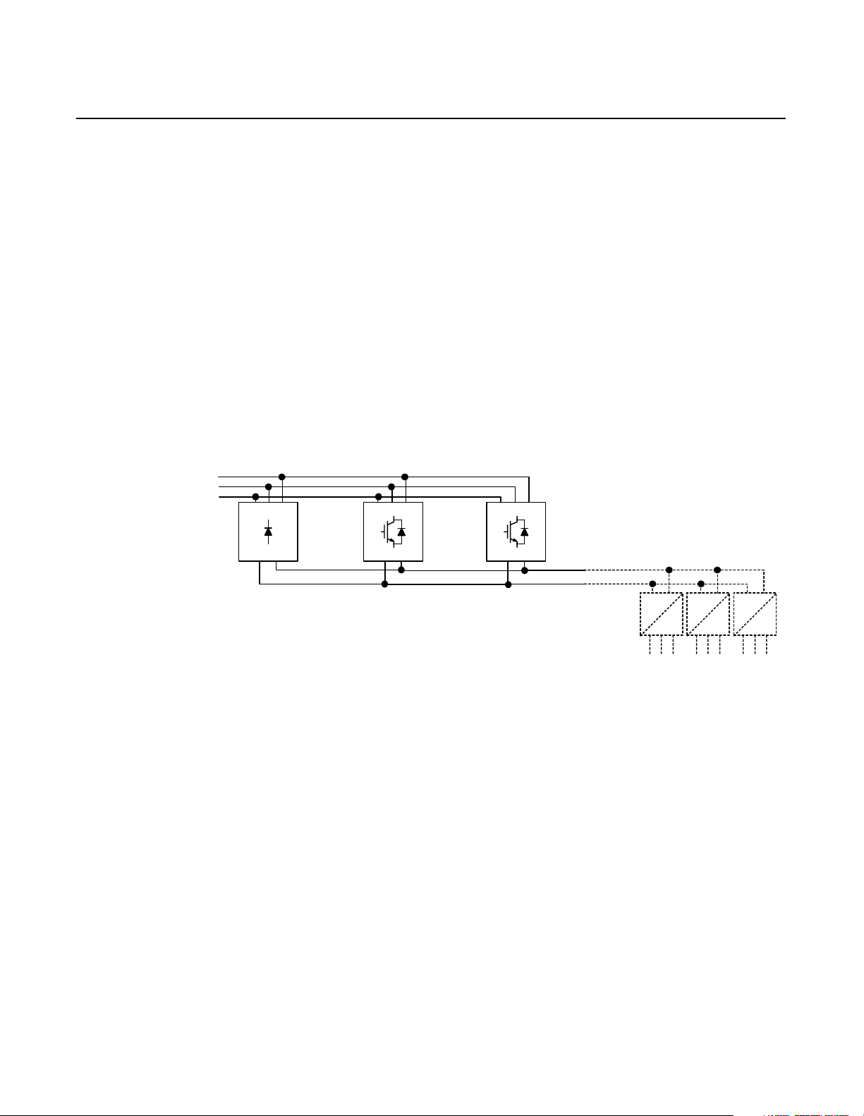
Parallel Configuration RGU//RGU Configurations
In an RGU//RGU configuration, each RGU supplies 100% motoring
current and 100% regenerative curr ent. When operating, the master
RGU evaluates the bus voltage and sends cur rent c ommands to the
slave RGUs through an RGU-to-RGU (R2R) communicati on
network. This allows the RGUs to operate together to supply the
appropriate current while maintaining a constant voltage on the DC
bus.
Figure 1.3
RGU//RGU Configuration
3-Phase
AC Line
RGU
RGU-to-RGU
Communications
Each RGU//RGU configuration has one master RGU in parallel with
either one or two slave RGUs. Each slave RGU includes a common
mode choke accommodate for minor switchi ng differences between
the RGUs and to reduce c irculat ing cur rents bet ween the master RGU
and the slave RGUs.
RGU RGU
Theory of Operation 1-3
DC Supply for
Drive Lineup
Master
3-Phase
AC Line
Figure 1.4
RGU//RGU Configuration–Master/Slave
Common Mode Choke
RGU RGU
R2R
Communication
Slave
DC Supply
for Drive
Lineup
Publication 2364P-5.01 December 1999
Page 16

1-4 Theory of Operation
Output of RGU//RGU Configurations
In an RGU//RGU configuration, each RGU (when enabled) switches
its IGBTs to maintain a constant voltage on the DC bus (which is
typically 1.52 times the input voltage).
In this pr ocess, t he maste r R GU evaluat es the bu s vol tage and se nds a
current com ma n d (whi ch is used t o corr ect the bu s voltag e ) to the
slave RGUs. Each RGU switches its IGBTs to regulate the current
(motoring or regenerative) needed to mainta in the bus voltage.
Figure 1.5
RGU//RGU Bus Voltage–Motoring or Regenerating
~1.52 x V AC
DC Bus Voltage
0 V DC
0%
% Load
100%
When the RGUs are not enabled, power is supplied through the freewheeling diodes. The diode bridge produces a voltage of 1.35 tim es
the input voltage with no load, and decre ases to 1.22 times the input
voltage at full load. During this operation, the RGUs do not regulate
the voltage or regenerat e any curr ent.
Figure 1.6
RGU//RGU Bus Voltage–Diode Bridge Operation (RGU Not Enabled)
1.35 x V AC
1.22 x V AC
DC Bus Voltage
0 V DC
0%
% Load
100%
Publication 2364P-5.01 December 1999
Page 17
3-Phase
AC Line
Theory of Operation 1-5
NRU//RGU Configurations
In the NRU//RGU configura tion, the NRU is used to supply m otoring
current to the DC bus, while the RGUs are used to regenerate current
to the AC line.
When motoring, the NRU operates to supply its maximum motoring
current to the DC bus, and the RGUs ope rate to supply 10% of their
maximum motoring current to the DC bus. When regenerating, the
NRU’s diode bridge stops operating, and the RGUs regener ate the
current back onto the AC line.
Figure 1.7
NRU//RGU Configuration
NRU
RGU RGU
RGU-to-RGU
Communications
DC Supply for
Drive Lineup
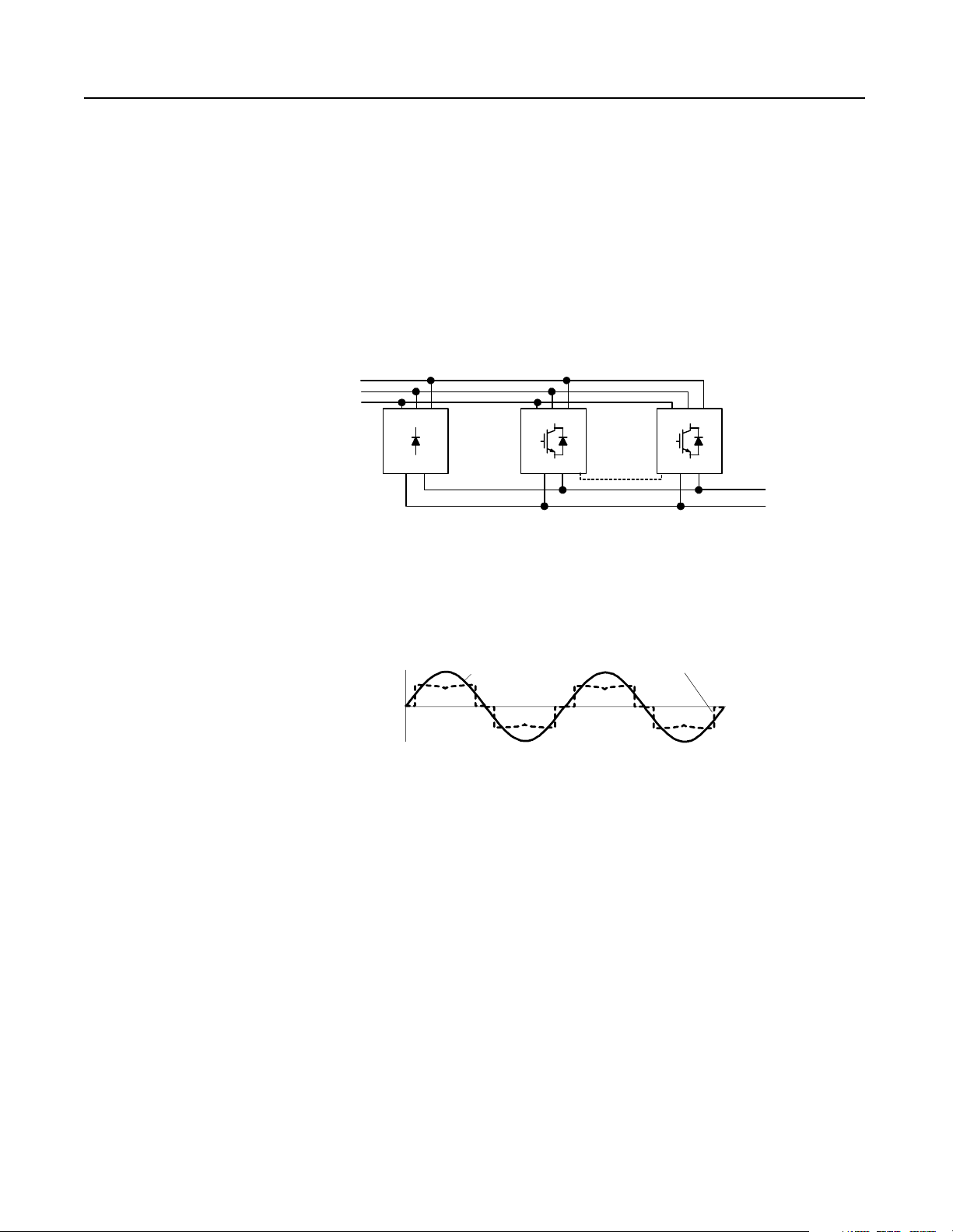
The NRU supplies motoring c urrent through its diode bridge, and the
RGU supplies motoring and regenerative current through its power
structure.
Figure 1.8
Line Waveform–NRU//RGU Configuration
Line Voltage
Line Current
Publication 2364P-5.01 December 1999
Page 18
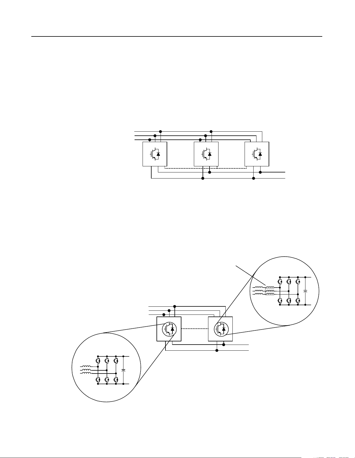
1-6 Theory of Operation
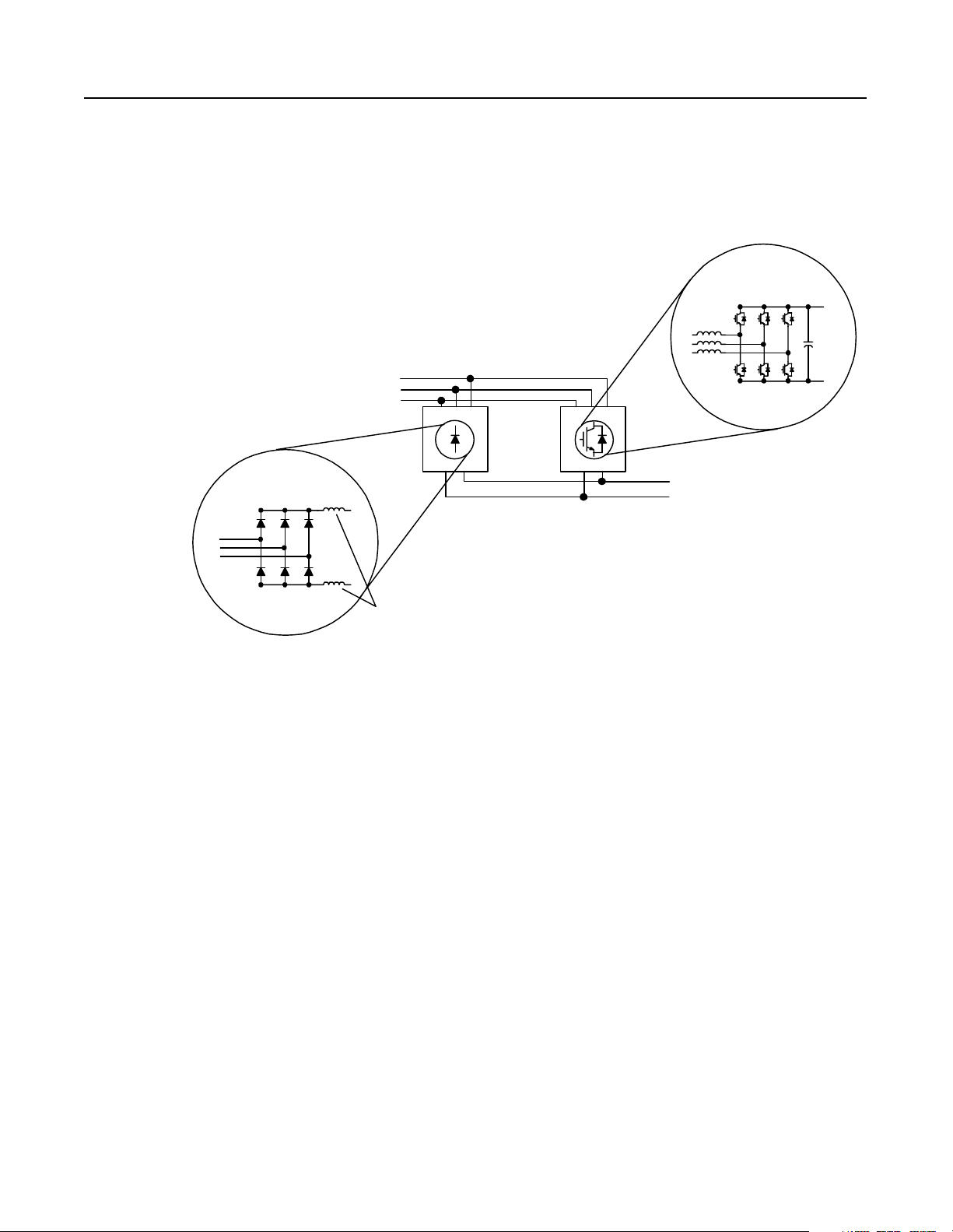
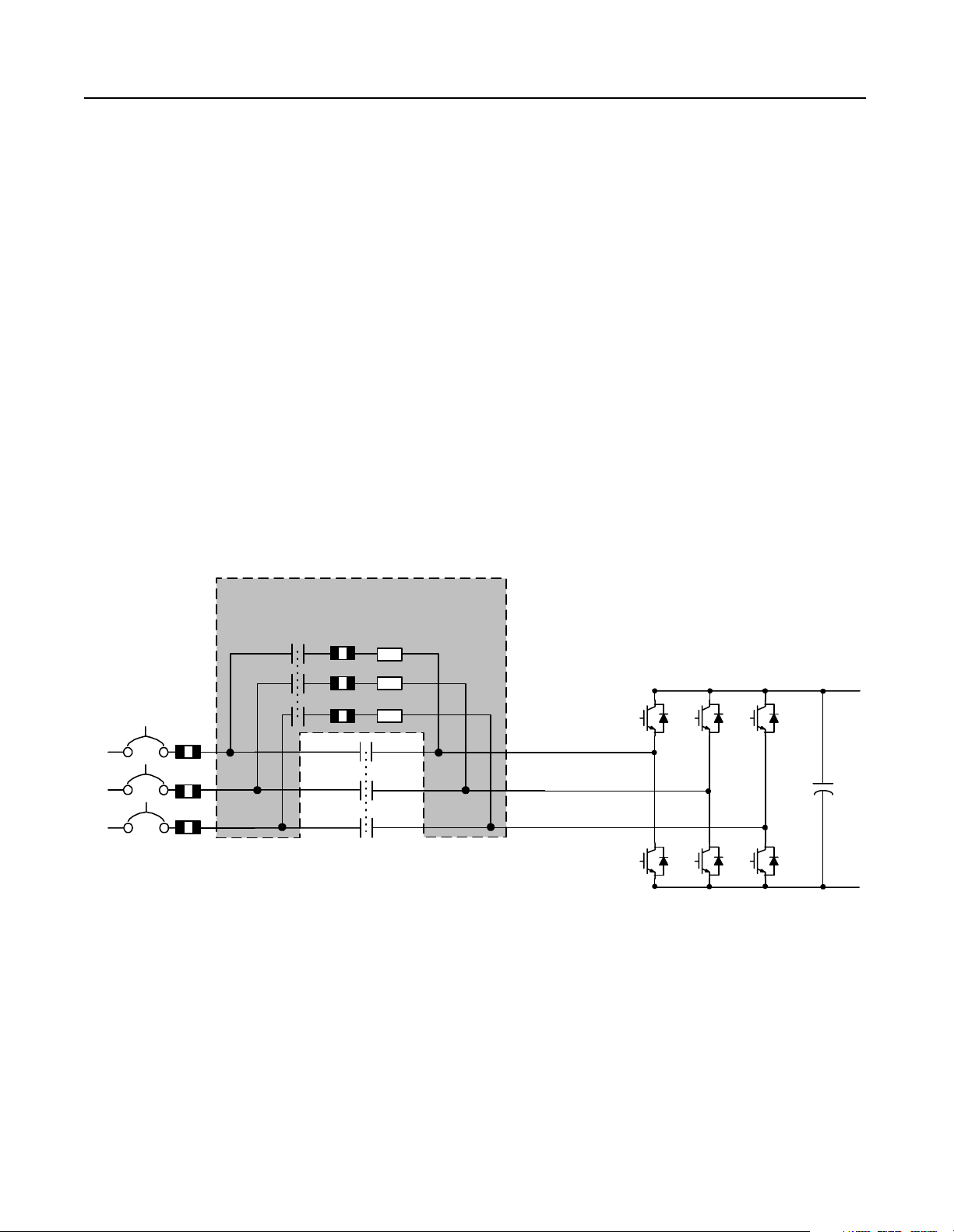
In the NRU//RGU configuration, the NRU has chokes on the DC bus.
These chokes reduce cir culating c urrent between the RGU and NRU.
If a slave RGU is in the configuration, the slave RGU will have a
common mode choke installed on its AC line.
Figure 1.9
NRU//RGU Configuration–Basic Components
Pow er Structure
(w ith IG BTs)
3-Phase
AC Line
NRU RGU
Diode Bridge
DC Supply
for Drive
Lineup
Chokes
The RGU evaluates the bus vo ltage and adjusts it s cu rrent to mai ntain
the nominal bus voltage. If there are two RGUs in the configuration,
the master RGU eva luates the vol tage and sends cur rent commands to
the slave RGU, and both RGUs will switch their IGBTs to regulate
the necessary current on the DC bus.
Publication 2364P-5.01 December 1999
Page 19
Theory of Operation 1-7
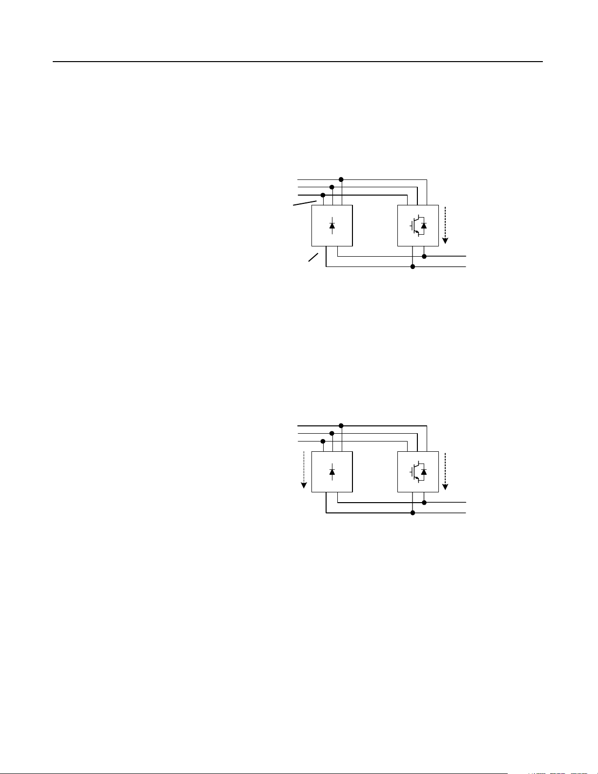
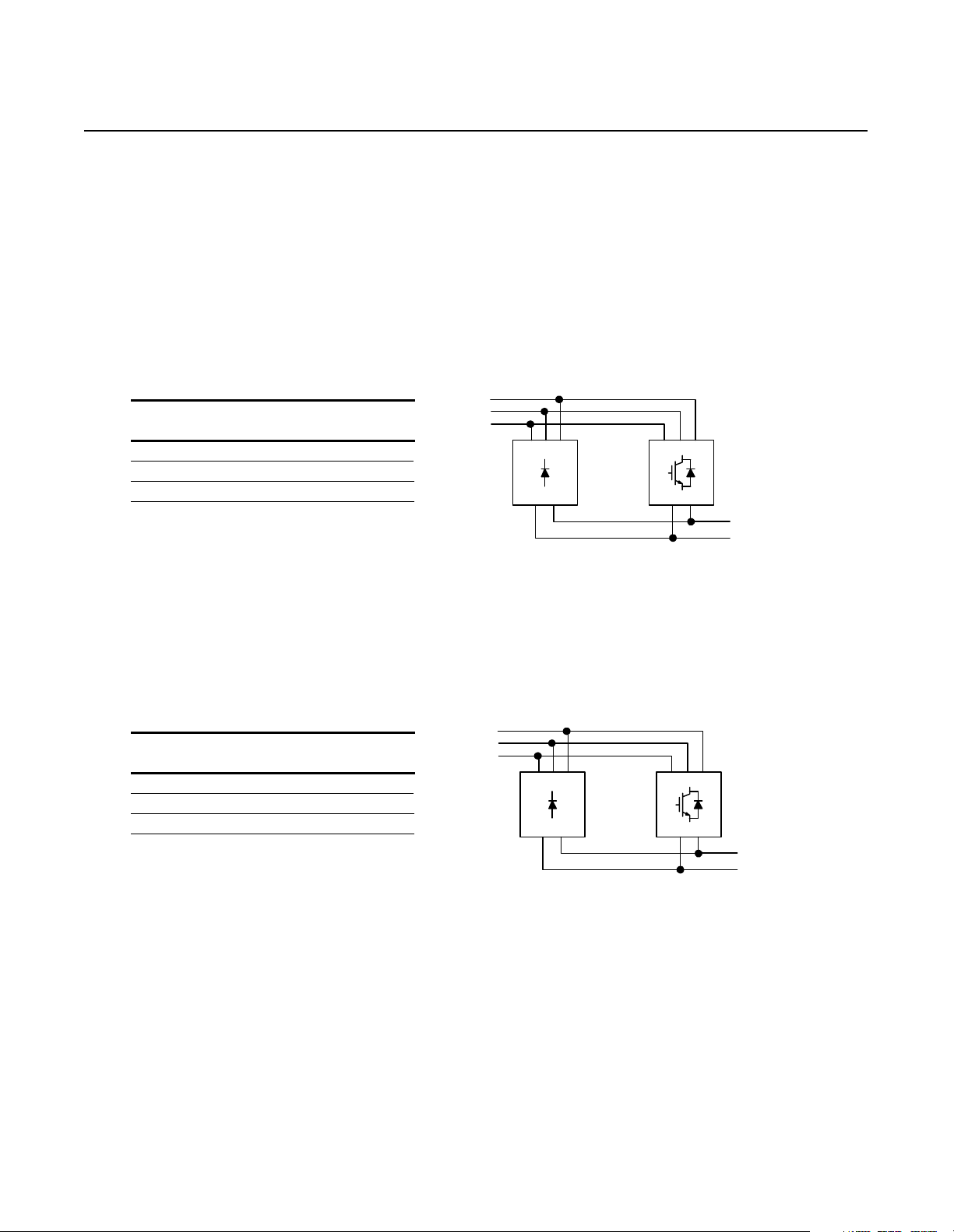
Output of NRU//RGU Configurations
The RGUs supply up to 10% of their rated amperes as motoring
current. In this first 10%, the RGUs will regula te the voltage to 1.52
times the line voltage, the voltage on the DC bus will be greater than
the AC line, and the diodes in the NRU will not conduct.
Figure 1.10
RGU Motoring–Load Up To 10% of RGU Rating
3-Phase
AC Line
smaller voltage
No
Current
v
RGUNRU
Current
(Up to 1 0% of the
RGU rating)
greater voltage
V
1.52 x AC Line
Voltage
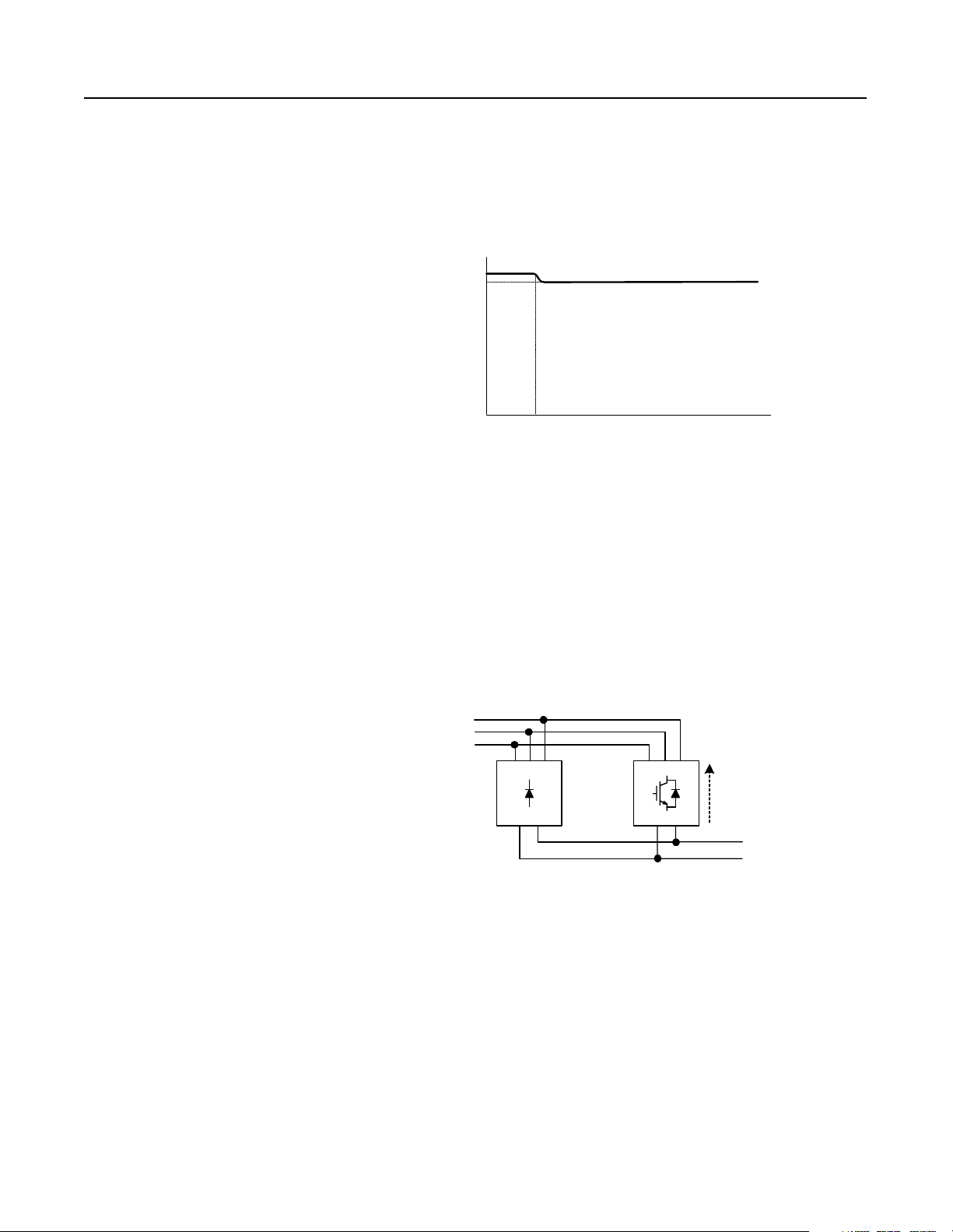
When the load increases beyond the fir st 10%, the RGU is no longe r
able to regu late the voltage (since the current limit is set to 10%), a nd
the bus voltage drops to a level where the diode s in the NRU can
conduct. The NRU then supplies the motoring current for the
remainder of the load, resulting in a bus voltage of 1.35 times the line
voltage.
Figure 1.11
RGU and NRU Motoring–Load Over 10% of RGU Rating
3-Phase
AC Line
Current
V
RGUNRU
v
Current
(10% of th e
RGU rating)
1.35 x AC Line
Voltage
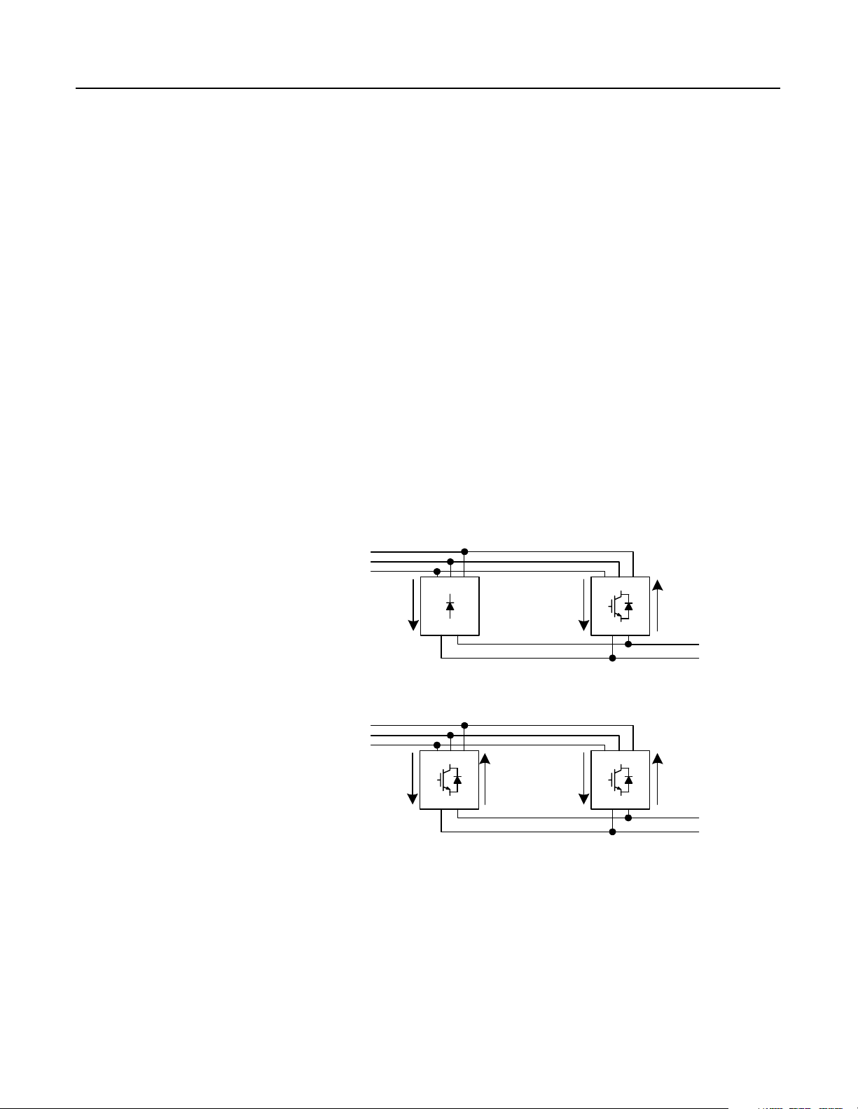
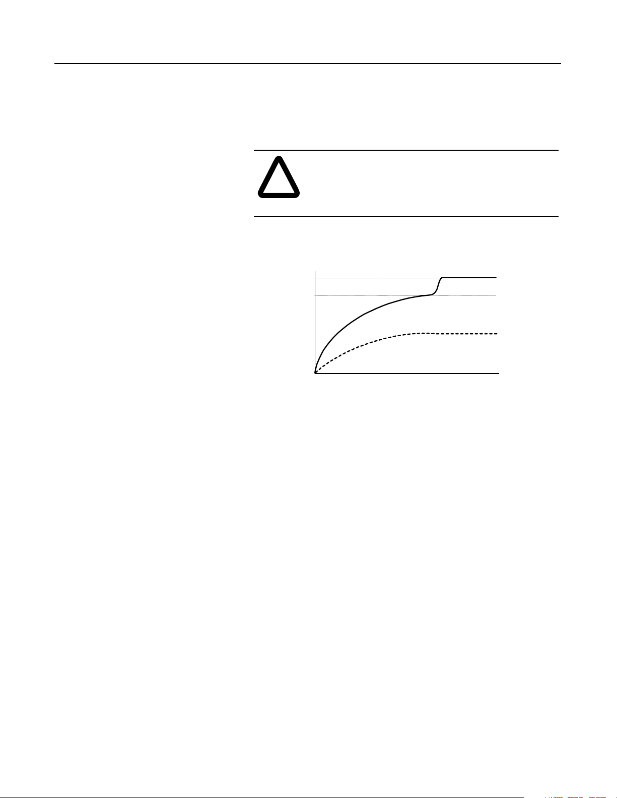
When the load drops under the 10% capabilit y of the RGUs, the
RGUs will begin to regulate the bus voltage again to 1.52 times the
line voltage, and the diodes in the NRU will stop c onducting.
Publication 2364P-5.01 December 1999
Page 20
1-8 Theory of Operation
The diagram below shows the NRU//RGU motoring bus voltage. The
RGUs regulate the bus voltage for the first 10% of the rated current
for the RGUs, then the NR Us su ppl y cu rren t fo r the rem ai nd er o f the
load (while the RGU current is limited to 10% of the RGU rating).
Figure 1.12
NRU//RGU Bus Voltage–Motoring
1.52 x V AC
1.35 x V AC
DC Bus Voltage
0 V DC
0%
10%
(of RGU rating)
% Load
100%
(Total NRU rating +
10% of RGU rating)
When the load is under 10% of the maximum motoring current, the
RGUs can regulate (or maintain) the bus voltage. The RGU (master
RGU) will evaluate the voltage on the bus, and will calculate the
current needed to maintai n the bus voltage. If a regenerative current
is needed to m aintain the voltage, the RGUs will begin switching
their IGBTs to regenerate current onto the AC line. The diodes in the
NRU will still not conduct current.
Figure 1.13
RGU Regenerating
3-Phase
AC Line
No
Current
v
RGUNRU
V
Current
(Up to 100% of the
RGU rating)
1.52 x AC Line
Voltage
Publication 2364P-5.01 December 1999
Page 21

Theory of Operation 1-9
The diagram below shows the NRU//RGU regenerative bus volta ge.
The RGUs regenerate up to 100% of their rated curre nt to the AC line
while the NRU diode bridge stops conduct ing.
Figure 1.14
NRU//RGU Bus Voltage–Regenerating
1.52 x V AC
DC Bus Voltage
0 V DC
0%
% Load
100%
When the RGUs are not enabled, only the NRU supplies current to
the DC bus. The bus voltage is 1. 35 times the line voltage at no load,
and decreases to 1.22 times the line voltage at full load. During this
operation, the RGUs do not regulate the voltage or regenerate any
current.
Figure 1.15
NRU//RGU Bus Voltage–RGUs Not Enabled
1.35 x V AC
1.22 x V AC
DC Bus Voltage
0 V DC
0%
% Load
100%
Publication 2364P-5.01 December 1999
Page 22
1-10 Theory of Operation
Motoring - Up to 10% of RGU Rated Amperes
3-Phase
AC Line
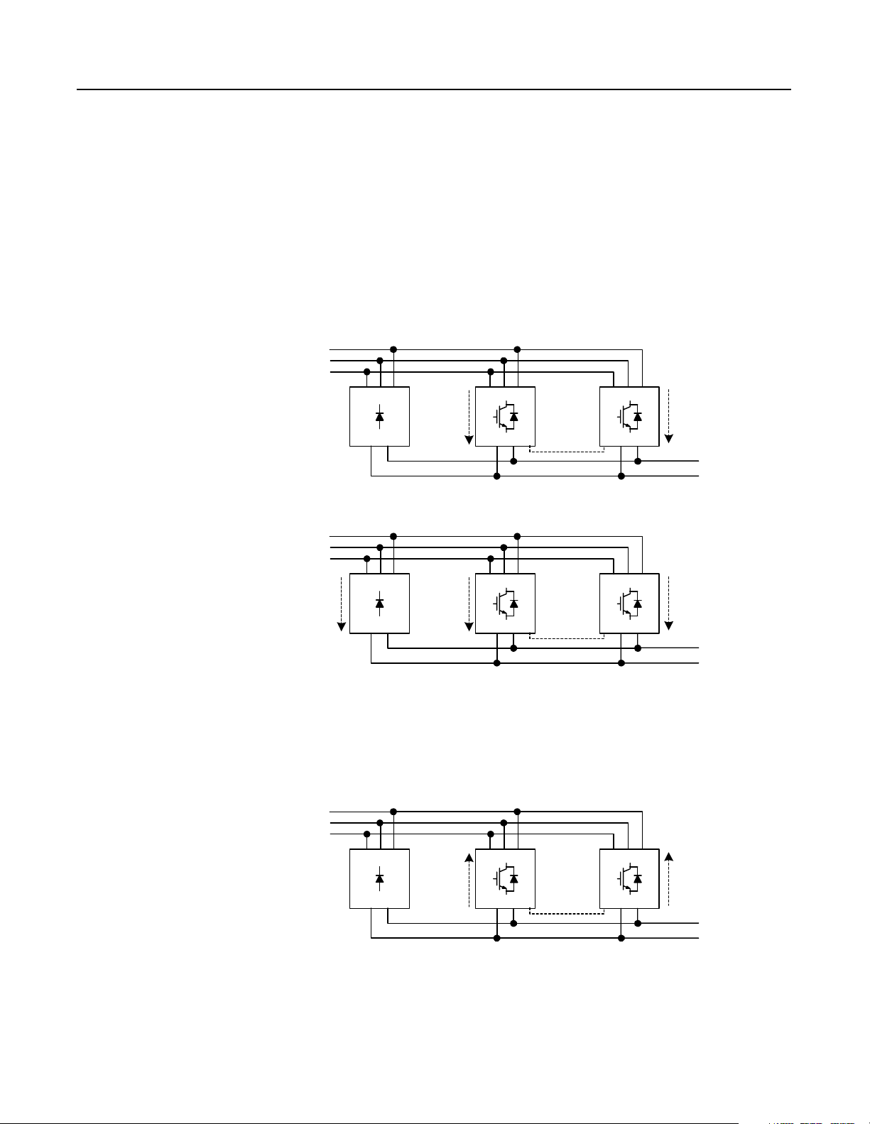
If there are two RGUs in the configuration, each RGU will supply up
to 10% of its rated motoring current . If the load is in this 10%, the
RGUs will regula te the bus voltage. The master RGU will evaluate
the bus voltage, and will determine the current required to maintai n
the nominal bus voltage (1.52 times the line voltage). The master
RGU will send a current command to the slave RGU, and both R GUs
will begin switching their IGBTs to provide the proper motoring or
regenerative current.
Figure 1.16
NRU With Two RGUs–Motoring
v
No
Current
NRU
V
Current
(Up to 10% of
RGU rated
amperes)
RGU RGU
RGU-to-RGU
Communications
Current
(Up to 10% of
the RGU rated
amperes)
1.52 x AC Line
Voltage
Motoring - Over 10% of RGU Rated Amperes
3-Phase
AC Line
Current
(Up to 100% of
the NRU rated
amperes)
V
NRU
v
Figure 1.17
NRU With Two RGUs–Regenerating
3-Phase
AC Line
No
Current
v
NRU
V
Current
(10% of
RGU rated
amperes )
Current
(Up to 100%
of RGU rated
amperes)
RGU RGU
RGU-to-RGU
Communications
RGU RGU
RGU-to-RGU
Communications
Current
(10% of the
RGU rated
amperes)
1.35 x AC Line
Current
(Up to 100% of
the RGU rated
amperes)
1.52 x AC Line
Voltage
Voltage
Publication 2364P-5.01 December 1999
Page 23
Theory of Operation 1-11
Precharge Operation
When the disconnects are closed and the start switch is turned
on, each RGU in the parallel configuration will begin its
precharge routine. This routine charges the capacitors on the
DC bus (the RGU capacitor bank and inverter capacitors) in a
controlled fashion.
T wo contactors (M1 and M2) are used to perform the precharge
operation in the K, L, a nd M-code RGUs (the N-code RGU precharge
circuit is slightly different).
When the disconnect ( MCP1 or CB1) is closed and the start switch is
turned on, the main contactor (M1) remains open, the precharge
contactor (M2) closes, and c urrent begins to flow through the
precharge circuit (bypassing the main 3-phase circuit). This
precharge circuit (which has a resistive load) charges up the capacitor
bank. As the bank approaches capacity, the main contactor (M1)
closes, the precharge contactor (M2) opens, the NRU circuit breaker
closes, and normal operation begins.
Circuit Breaker or
MCP
(CB1 or MCP1)
Precharge
Contactor
(M2)
Main
Contactor
(M1)
Figure 1.18
Precharge Circuit
Precharge Circuit
R
Note:
The precharge circuitry is slightly
different in the N-code RGU. See the product
schematics for further details.
Publication 2364P-5.01 December 1999
Page 24
1-12 Theory of Operation
The RGUs will precharge the capa citors on the bus until the bus
voltage rises to be equal to the lin e volt age. Then, the precharge
circuit will open, the main circuit will close, the NRU circuit breake r
will close, and the DC bus voltage will rise to 1.35 times the line
voltage.
ATTENTION: If there is too much capacitance on the
DC bus, the RGUs may not be able to raise the bus
!
voltage to the threshold f or normal operation, resul ting
in damage to equipment.
Figure 1.19
Precharge Voltage
1.35 x V AC
DC Bus Voltage
1 x V AC
0 V DC
0 sec
Precharging
Time
Normal Diode-Bridge
Operation
Unable to Precharge
(Too many inv erters)
t
Publication 2364P-5.01 December 1999
Page 25
Chapter 2
R1 and S1-Code Parallel Configurations
R1-Code Parallel Configuration The R1-code parallel configur ation is a common DC bus front-end
unit consisting of an D-code NRU in parall el with a K-code RGU.
Figure 2.1
R1-Code Parallel Configuration–Information
R1-code Parallel ConfigurationR1-code Ratings
Input Voltage
(V AC)
380 1520
460
575
DC Bus Current
(A DC)
1520
1520
Rated DC Bus
kW
780
944
1180
D-code
NRU
K-code
RGU
S1-Code Parallel Configuration The S1-code parallel configuration is a common DC bus front-end
unit consisting of an E-code NRU in parallel with a K-code RGU.
Figure 2.2
S1-Code Parallel Configuration–Information
S1-code Parallel ConfigurationS1-code Ratings
Input Voltage
(V AC)
380 2020
460
575
DC Bus Current
(A DC)
2020
2020
Rated DC Bus
kW
1036
1254
1568
E-code
NRU
K-code
RGU
Note: Information for the D-code NRU and E-code NRU can be
found in publication 2364E-5.01. Information for the K-code
RGU can be found in publication 2364F-5.01.
Publication 2364P-5.01 December 1999
Page 26
2-2 R1 and S1-Code Parallel Configurations
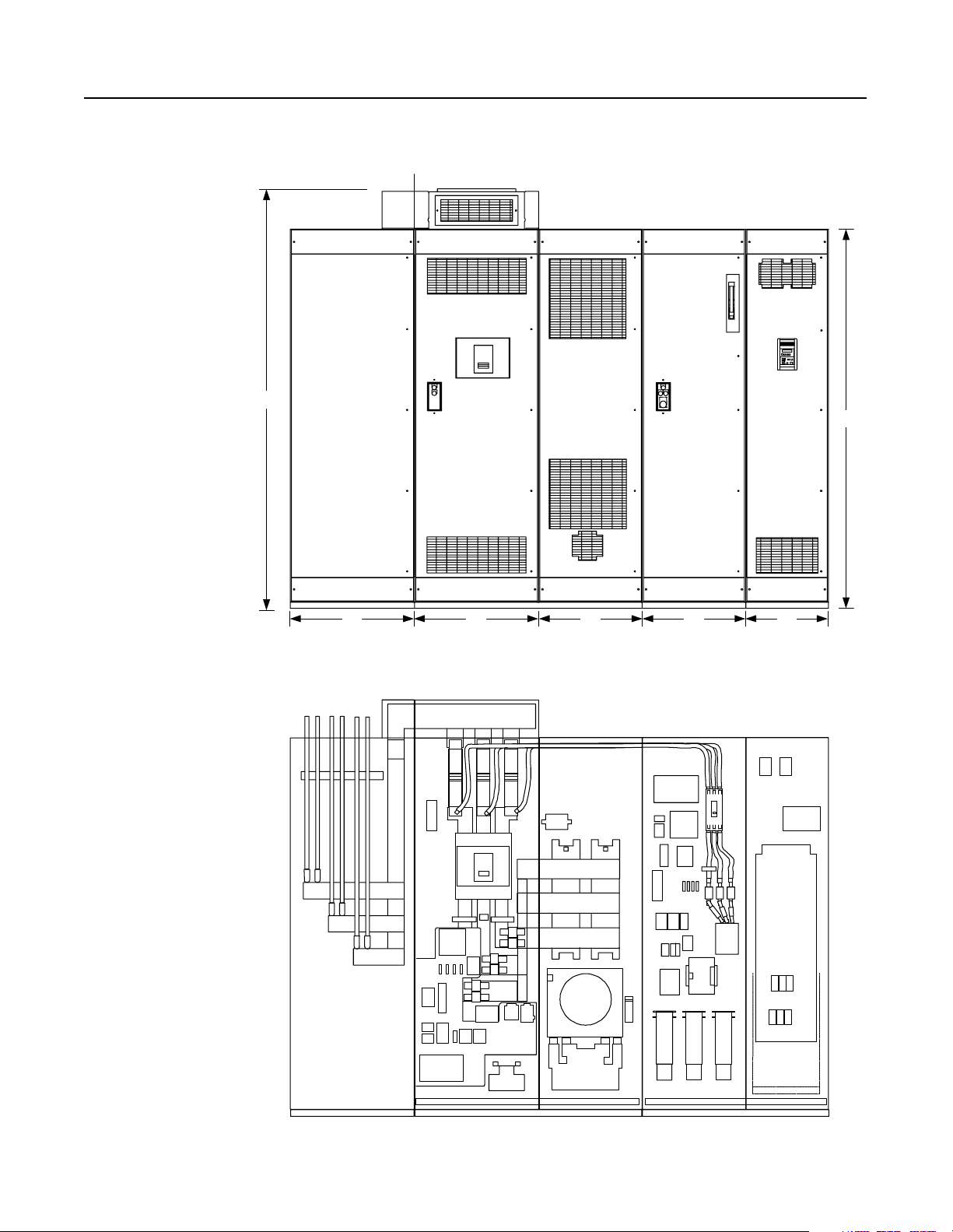
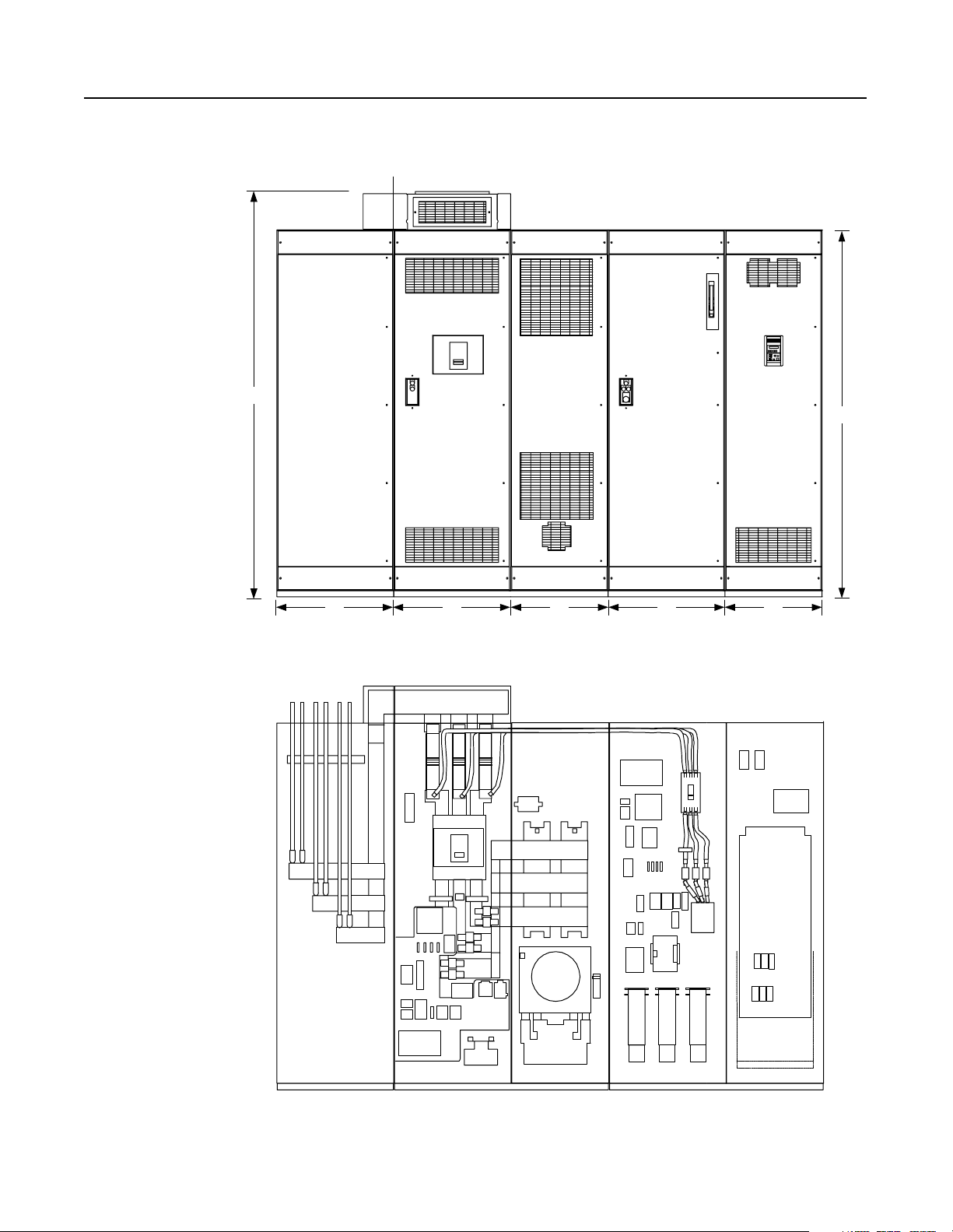
Component Layout Figure 2.3
Enclosure Layout
Front View
Shipping Split
101.25"
91.5"
Cutaway View
30" 30" 25" 25" 20"
Customer Supplied
AC Input Lines
Publication 2364P-5.01 December 1999
Feeder D-code NRU (1500A) K-code RGU
Page 27
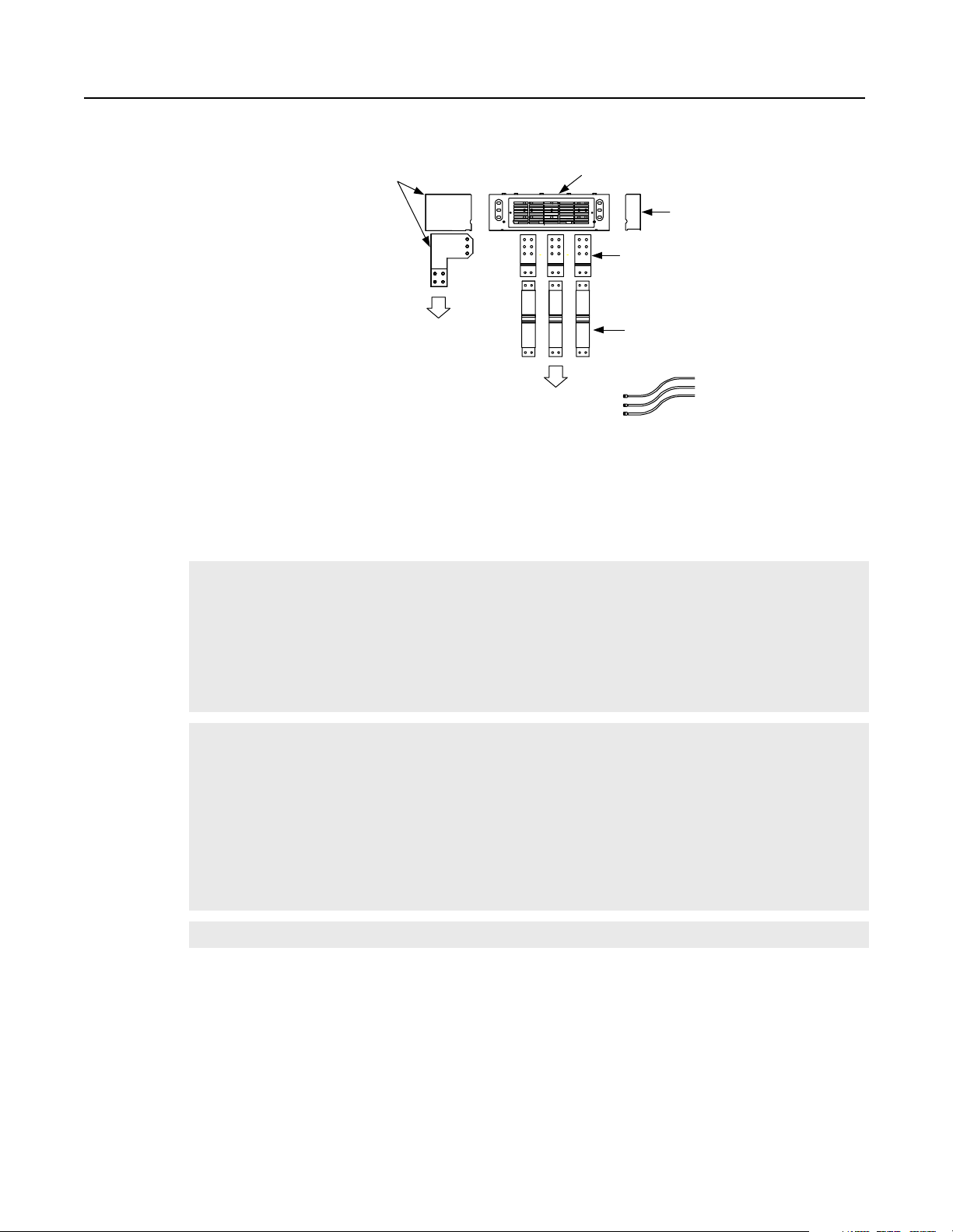
Figure 2.4
Overhead Bus Assembly
Feeder
Splice Kit
R1 and S1-Code Parallel Configurations 2-3
30" Overhead
Bus Assembly
End Cap
4" Bus Tabs
To Feeder Buswork
To NRU circuit breaker
Flex Bus
Drop Tabs
New and Revised NRU and RGU Components in the R1 and S1 Configurations
NRU
RGU
CB1 2000A, RD-frame with motor operator, aux contact (2NO/2NC)
EA10
F4, F6
Control power filter, 4kHz
Primary fuse for 5kVA control transformer
Primary fuse for 10kVA control transformer (Opt 6P)
25A, KLDR (for 380V AC input)
30A, KLDR (for 460V AC input)
25A, KLDR (for 575V AC input)
PT1
TB10
CR4
F4, F6
20A, KLDR (for 460V AC input)
17.5A, KLDR (for 575V AC input)
Control power transformer, 5kVA
Control terminal block, 30A, 600V
Precharge Lockout Relay (2NO/2NC)
Primary fuse for 2kVA transformer
Control power transformer, 10kVA (Opt 6P)
10A, KLDR (for 380V AC input)
9A, KLDR (for 460V AC input)
8A, KLDR (for 575V AC input)
F21, F22 DC bus fuses, 250A, 700V, 170M
F25
PT1
TR1
TB4
Fuse, NRU CB1 motor operator, 10A, KLDR
Control power transformer, 2kVA
Timer relay (3NO/1NC)
Control Terminal block, 30A, 600V
35A, KLDR (for 380V AC input)
The RGU AC line is connected to the
bus stubs on the NRU circuit breaker
Overhead bus assembly
Publication 2364P-5.01 December 1999
Page 28
2-4 R1 and S1-Code Parallel Configurations
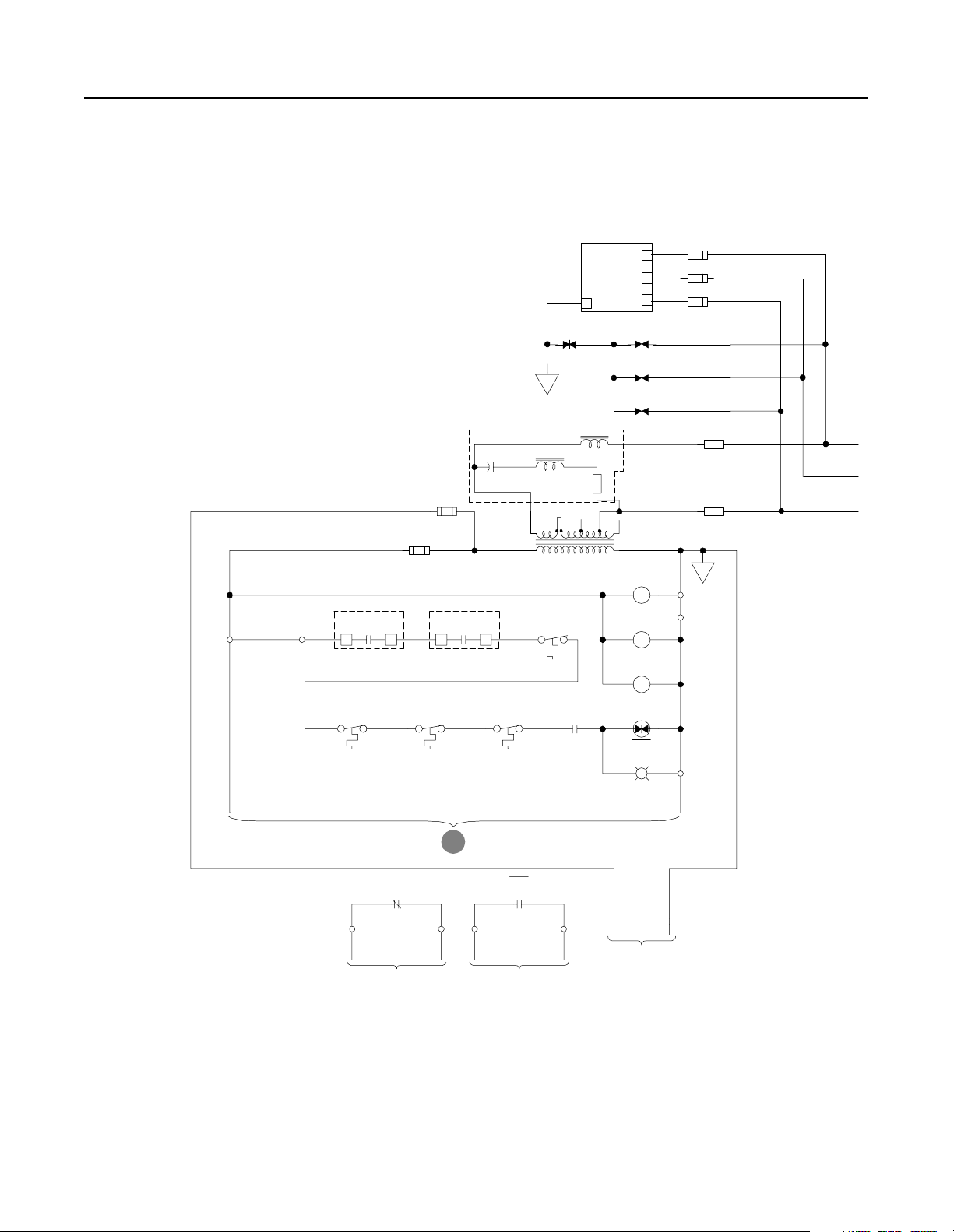
Schematics Figure 2.5
Schematics
NRU
TB1-1
Optional
Remote
Interlock
(JMPR)
TB1-2
Airflow Loss
Bridge Bay
1
EA5-CR
CB Bay
Overtemp
SP4
EA3
Line RC
Suppressor
Com
L1
L2
L3
SP1
F14
F15
F16
SP2
PE
SP3
4KHZ Control Power Filter
EA10
F4
F8
F7
(X1)
460VAC
115VAC
PT1
(X2)
MTR1
Rect. Bridge
MTR2
Choke Comp.
MTR3
CB Bay
CR2
Right
Choke
Overtemp
CH11-TG
CR1
Airflow Loss
3
CB Bay
13
EA6-CR
Heatsink
Overtemp
Left
Heatsink
Overtemp
F6
PE
TB1-9
TB1-10
Publication 2364P-5.01 December 1999
S3
Phase Loss
TB1-3
S1
To Ground Fault Detector
B
and Airflow Sensors
CR1
TB1-4 TB1-5 TB1-6
S2
Fault
CR2
Fault
PL2
A
Not
Faulted
1
L
C
A
V
0
2
1
115VAC
Control Bus To
Inverter Units
N
C
A
V
0
2
1
Page 29
R1 and S1-Code Parallel Configurations 2-5
Customer Supplied
3-phase Input
-Bus
Heat
Sink
D1
D3
CT1
F1 F2 F3
M
CB1- NRU
Note:
Control power for this
motorized breaker originates
in the RGU. Do not operate
this breaker manually.
AC Line
Current
AM1
F11
F12
F13
Heat
Sink
D2
D4
A
B
CR
C
+Bus
A
To RGU
AC Input
CR1
Phase
Loss
Relay
B
From NRU
Control Power
B
From NRU
Control Power
7
115VAC
ACN-ACL +
ACG
To Grounding
9
PS1
Resistor
Input
624
TB1-8
TB1-7
1012
Ground Fault
Detector
VM2
J2
3
To Cust omer
Monitoring Device
EA5
J2
In15
Sig 1
In26
+5 2
Com 3
J11
S5
Y
R
B
Flow
Sensor
D5
EA4
Bridge Suppressor
EA2
Bus Indicator PCB
+Bus
-Bus
(X4)
CH11 CH11
(X3)
DC Horizontal Bus To
LED1
LED2
VM1
DC Bus Voltage
Inverter Units
D6HS1 HS2
DC Bus
Energized
R
PL1
(X1)
(X2)
Publication 2364P-5.01 December 1999
Page 30
2-6 R1 and S1-Code Parallel Configurations
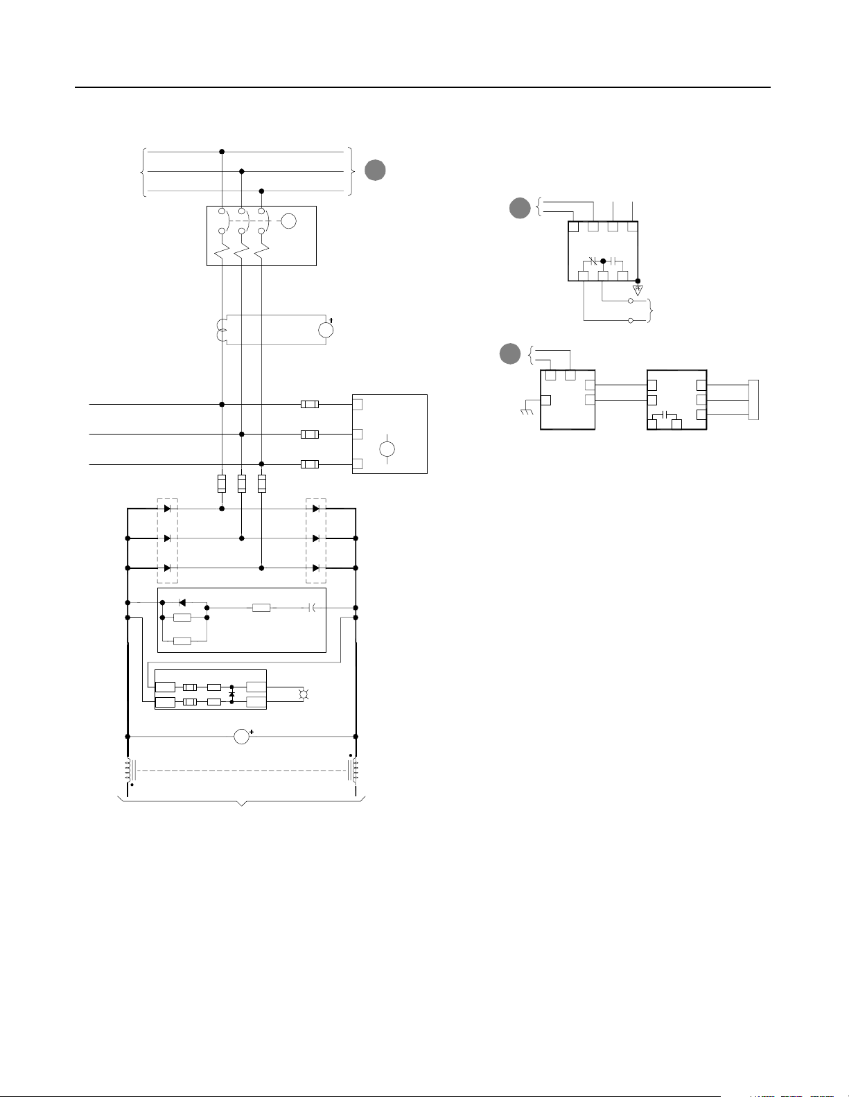
Figure 2.6
Schematics (cont.)
RGU
D
To
CB1-NRU
circuitry
TB1-1
Optional
Remote
Interlock
(JMPR)
RGU/DC Bus
Supply
Off On
S12
TB1-2
TR1
CR4
TR1
From
A
3-phase
AC Input
CB1-RGU
4KHZ Control Power Filter
EA10
SP4
SP1
SP2
PE
SP3
F4
460VAC
F7
(X1)
115VAC
(X2)
F25
RGU Uni t Not
Faulted
14
TB6 TB6
Isolat i on Boa rd
F6
PT1
MTR1
RGU Door Fan
MTR2
RGU Door Fan
CR2
Fault
PL2
A
Not
Faulted
PE
TB1-9
TB1-10
Fault
C
To RGU Input
Fuses
CR2
TB1
TR1
Precharge
11
CR4
12
TB1
CR3
CR4
Timer
M2
Precharge
(20 sec)
TB1-5 TB1-6
Avail able f o r
Customer Use
6
TB6
CR3
Publication 2364P-5.01 December 1999
Bus Control
Isolation Board
CR3
CR4
M1
TB6
TB4-4
9
TB10-7
E
CB1-NRU-A
To RGU
Control
Circuitry
TB10-8
TB4-5
CR3
Pilot
CR4
Precharge
Lockout
M1
Main
External M ain
Enable
F
Isolation Board
To RGU
Page 31

D
Control Power
From RGU
R1 and S1-Code Parallel Configurations 2-7
TB4-8
CB1-NRU
PE
TR1
CR3
TR1
Spring Windup
Wht/Red
TB4-6
TB10-1
Blu
TB4-9
TB10-3
TB4-7 TB10-4
TB4-3
TB10-5
TB10-7
TB4--4 TB4-5
Blk
Red
Blk
LS
X
Y
Y
Y
X
X
LS
M
Y
X
CB1-NRU-A
CB1-NRU-B
Blk
TB10-10
CB1-NRU-A
CB1-NRU-B
TB4-1
Not
Used
TB4-2
Open
Motor
Close
UVR
TB10-2
Wht
TB10-6
Red
TB10-8
Blu
TB10-9
Red
TB10-11
Blu
TB10-12
Publication 2364P-5.01 December 1999
Page 32

2-8 R1 and S1-Code Parallel Configurations
Figure 2.7
Schematics (cont.)
B
From RGU
AC Line
From RGU
Control
Circuitry
AC
Rtn
R10
F2
R11
F3
F4
R12
CT1
F17
F18
F19
Bridge
Fan
Rs
Ss
Ts
0
6
2
2
1
1
-
-
-
1
1
1
J
J
J
CT3
To
PE
Gnd
J7
P1
1
6
-
-
1
1
J
J
M2
CH11
F1
M1
F2
F3
From RGU
E
Control Power
CH1
CH2
CH3
Isolation
Board
TB5
1
Fault
F
Reset
S11
Enable
2
Fault Reset
3
External Main
4
Common
SW1 Settings
115VAC
OffX
24VDCOn
For TB5-1, -2, -3
Burden Resistors
1
TB1
Publication 2364P-5.01 December 1999
To RGU
Control
Circuitry
To RGU
Control
Circuitry
TB6
1
3
4
6
8
9
Aux Control
Fault
Bus
Control
TB2
TB3
3
1
TB2 Resistor
Not Required
3
1
3
J2
Page 33

R1 and S1-Code Parallel Configurations 2-9
d
r
a
o
B
r
e
b
b
u
n
S
To System Network
UP
C1
G
E1
UN
C1
G
E1
J7
Main Bus
DC-DC
Converter
TP3
-t
J6
Bridge Thermal
Sensor (NTC)
J12
Gate Drivers
TP5
-15V+24V +15V
Shd
(+)
Horizontal
DC Bus
(-)
F1
G
G
24V
DC-DC
Aux 24V
J10
WP
C1
E1
Cap
Bank
WN
C1
E1
J10
+15V
-15V
+5V
+12V
-12V
J1
J3
J7
d
r
a
o
B
G
r
e
b
E1
b
u
n
S
VN
C1
G
E1
J8
F1
d
r
a
o
B
r
e
b
b
u
n
S
Gate Driver Board
+24V
VP
C1
Converter
TP8TP4TP6
TP9
+12V+5V -12V
Main Control Bo a rd
J2
RIO Adapter Option
1
1203-GM1
2
3
Y
R
YY
SW1
SW2
J4
Blu
1
SW3
Shd
Clr
2
Off
On
Off
On
Off
On
J1
J8 J9
2
Power
B
T
Supply
Filter
1
Board
B
T
J11
TB7
P13
TB4
TB1
+
-
PE
TE
2
1
1
2
1
2
3
4
5
6
7
8
9
10
+Bus
-Bus
+
-
- Analog In 1
+ Analog In 1
Analog In 1 Common
- Analog In 2
+ Analog In 2
Analog In 2 Common
Analog Out 1
Analog Out 1 Common
Analog Out 2
Analog Out 2 Common
Horizontal DC Bus
To Inve rter Units
EA2
Bus Indicator Board
EA4
Bus Suppressor
LED1
LED2
PL1
R
DC Bus
Energized
RIO Ext SCANport 1 SCANport 2 R2R Comm
Publication 2364P-5.01 December 1999
Page 34

2-10 R1 and S1-Code Parallel Configurations
Publication 2364P-5.01 December 1999
Page 35

Chapter 3
R2 and S2-Code Parallel Configurations
R2-Code Parallel Configuration The R2-code parallel configur ation is a common DC bus front-end
unit consisting of an D-code NRU in parall el with a L-code RGU.
Figure 3.1
R2-Code Parallel Configuration–Information
R2-code Parallel ConfigurationR2-code Ratings
Input Voltage
(V AC)
380 1536
460
575
DC Bus Current
(A DC)
1536
1533
Rated DC Bus
kW
788
954
1190
D-code
NRU
L-code
RGU
S2-Code Parallel Configuration The S2-code parallel configuration is a common DC bus front-end
unit consisting of an E-code NRU in parallel with a L-code RGU.
Figure 3.2
S2-Code Parallel Configuration–Information
S2-code Parallel ConfigurationS2-code Ratings
Input Voltage
(V AC)
380 2036
460
575
DC Bus Current
(A DC)
2036
2033
Rated DC Bus
kW
1045
1265
1578
E-code
NRU
L-code
RGU
Note: Information for the D-code NRU and E-code NRU can be
found in publication 2364E-5.01. Information for the L-code
RGU can be found in publication 2364F-5.01.
Publication 2364P-5.01 December 1999
Page 36
3-2 R2 and S2-Code Parallel Configurations
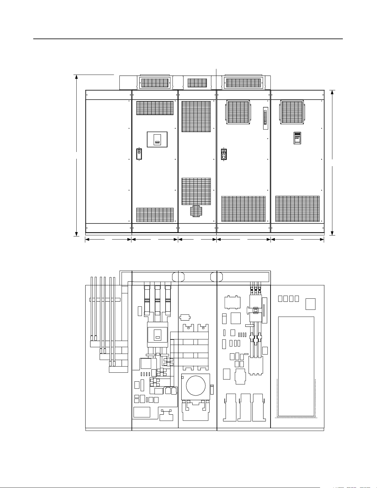
Component Layout Figure 3.3
Enclosure Layout
Front View
Shipping Split
101.25"
91.5"
30" 30" 25" 30" 25"
Cutaway View
Note: The D-code NRU has only
one AC line fuse per phase.
Customer Supplied
AC Input Lines
Feeder D-code NRU (1500A) or E-code NRU (2000A) L-code RGU
Publication 2364P-5.01 December 1999
Page 37

Figure 3.4
Overhead Bus Assembly
Feeder
Splice Kit
R2 and S2-Code Parallel Configurations 3-3
30" Overhead
Bus Assembly
End Cap
4" Bus Tabs
To Feeder Buswork
To NRU circuit breaker
Flex Bus
Drop Tabs
New and Revised NRU and RGU Components in the R2 and S2 Configurations
NRU CB1 2000A, RD-frame with motor operator, aux contact (2NO/2NC)
RGU
EA10
F4, F6
PT1
TB10
CR4
F4, F6
F21, F22 DC bus fuses, 500A, 700V, 170M
F25
PT1
TR1
TB4
Control power filter, 2kHz
Primary fuse for 5kVA control transformer
25A, KLDR (for 380V AC input)
20A, KLDR (for 460V AC input)
17.5A, KLDR (for 575V AC input)
Control power transformer, 5kVA
Control terminal block, 30A, 600V
Precharge Lockout Relay (2NO/2NC)
Primary fuse for 5kVA transformer
25A, KLDR (for 380V AC input)
20A, KLDR (for 460V AC input)
17.5A, KLDR (for 575V AC input)
Fuse, NRU CB1 motor operator, 10A, KLDR
Control power transformer, 5kVA
Timer relay (3NO/1NC)
Control Terminal block, 30A, 600V
Primary fuse for 10kVA control transformer (Opt 6P)
35A, KLDR (for 380V AC input)
30A, KLDR (for 460V AC input)
25A, KLDR (for 575V AC input)
Control power transformer, 10kVA (Opt 6P)
The RGU AC line is connected to the
bus stubs on the NRU circuit breaker
Overhead bus assembly
Publication 2364P-5.01 December 1999
Page 38

3-4 R2 and S2-Code Parallel Configurations
Schematics Figure 3.5
Schematics
NRU
TB1-1
Optional
Remote
Interlock
(JMPR)
TB1-2
Airflow Loss
Bridge Bay
1
EA5-CR
CB Bay
Overtemp
SP4
EA3
Line RC
Suppressor
Com
L1
L2
L3
SP1
F14
F15
F16
SP2
PE
SP3
2KHZ Control Power Filter
EA10
F4
F8
F7
(X1)
460VAC
115VAC
PT1
(X2)
MTR1
Rect. Bridge
MTR2
Choke Comp.
MTR3
CB Bay
CR2
Right
Choke
Overtemp
CH11-TG
CR1
Airflow Loss
3
CB Bay
13
EA6-CR
Heatsink
Overtemp
Left
Heatsink
Overtemp
F6
PE
TB1-9
TB1-10
Publication 2364P-5.01 December 1999
S3
Phase Loss
TB1-3
S1
To Ground Fault Detector
B
and Airflow Sensors
CR1
TB1-4 TB1-5 TB1-6
S2
Fault
CR2
Fault
PL2
A
Not
Faulted
1
L
C
A
V
0
2
1
115VAC
Control Bus To
Inverter Units
N
C
A
V
0
2
1
Page 39

R2 and S2-Code Parallel Configurations 3-5
Customer Supplied
3-phase Input
-Bus
Heat
Sink
D1
D3
CT1
F1 F2 F3
M
CB1- NRU
Note:
Control power for this
motorized breaker originates
in the RGU. Do not operate
this breaker manually.
AC Line
Current
AM1
F11
F12
F13
Heat
Sink
D2
D4
A
B
CR
C
+Bus
A
To RGU
AC Input
CR1
Phase
Loss
Relay
B
From NRU
Control Power
B
From NRU
Control Power
7
115VAC
ACN-ACL +
ACG
To Grounding
9
PS1
Resistor
Input
624
TB1-8
TB1-7
1012
Ground Fault
Detector
VM2
J2
3
To Cust omer
Monitoring Device
EA5
J2
In15
Sig 1
In26
+5 2
Com 3
J11
S5
Y
R
B
Flow
Sensor
D5
EA4
Bridge Suppressor
EA2
Bus Indicator PCB
+Bus
-Bus
(X4)
CH11 CH11
(X3)
DC Horizontal Bus To
LED1
LED2
VM1
DC Bus Voltage
Inverter Units
D6HS1 HS2
DC Bus
Energized
R
PL1
(X1)
(X2)
Publication 2364P-5.01 December 1999
Page 40

3-6 R2 and S2-Code Parallel Configurations
Figure 3.6
Schematics (cont.)
RGU
D
To
CB1-NRU
circuitry
TB1-1
Optional
Remote
Interlock
(JMPR)
RGU/DC Bus
Supply
Off On
S12
TB1-2
TR1
CR4
TR1
From
A
3-phase
AC Input
CB1-RGU
2KHZ Control Power Filter
EA10
SP4
SP1
SP2
PE
SP3
F4
460VAC
F7
(X1)
115VAC
(X2)
F25
RGU Uni t Not
Faulted
14
TB6 TB6
Isolat i on Boa rd
F6
PT1
MTR1,2
Bay Door Fans
MTR3,4
Bay 1 Door Fans
CR2
Fault
PL2
A
Not
Faulted
PE
TB1-9
TB1-10
Fault
C
To RGU Input
Fuses
CR2
TB1
TR1
Precharge
11
CR4
12
TB1
CR3
CR4
Timer
M2
Precharge
(20 sec)
TB1-5 TB1-6
Avail able f o r
Customer Use
6
TB6
CR3
Publication 2364P-5.01 December 1999
Bus Control
Isolation Board
CR3
CR4
M1
TB6
TB4-4
9
E
CB1-NRU-A
TB10-7 TB10-8
To RGU
Control
Circuitry
TB4-5
CR3
Pilot
CR4
Precharge
Lockout
M1
Main
External M ain
Enable
F
Isolation Board
To RGU
Page 41

D
Control Power
From RGU
R2 and S2-Code Parallel Configurations 3-7
TB4-8
CB1-NRU
PE
TR1
CR3
TR1
Spring Windup
Wht/Red
TB4-6
TB10-1
Blu
TB4-9
TB10-3
TB4-7 TB10-4
TB4-3
TB10-5
TB4-4 TB4-5
TB10-7
Blk
Red
Blk
LS
X
Y
Y
Y
X
X
LS
M
Y
X
CB1-NRU-A
CB1-NRU-B
Blk
TB10-10
CB1-NRU-A
CB1-NRU-B
TB4-1
Not
Used
TB4-2
Open
Motor
Close
UVR
TB10-2
Wht
TB10-6
Red
TB10-8
Blu
TB10-9
Red
TB10-11
Blu
TB10-12
Publication 2364P-5.01 December 1999
Page 42

3-8 R2 and S2-Code Parallel Configurations
Figure 3.7
Schematics (cont.)
B
From RGU
AC Line
From RGU
Control
Circuitry
AC
Rtn
R10
F2
R11
F3
F4
R12
CT1
F17
F18
F19
Bridge
Fan
Rs
Ss
Ts
0
6
2
2
1
1
-
-
-
1
1
1
J
J
J
CT3
To
PE
Gnd
J7
P1
1
6
-
-
1
1
J
J
M2
F1
M1
F2
F3
From RGU
E
Control Power
CH1
CH2
CH3
CH11
Isolation
Board
TB5
1
Fault
F
Reset
S11
Enable
2
Fault Reset
3
External Main
4
Common
SW1 Settings
115VAC
OffX
24VDCOn
For TB5-1, -2, -3
Burden Resistors
1
TB1
Publication 2364P-5.01 December 1999
To RGU
Control
Circuitry
To RGU
Control
Circuitry
TB6
1
3
4
6
8
9
Aux Control
Fault
Bus
Control
TB2
TB3
3
1
TB2 Resisto r
Not Required
3
1
3
J2
Page 43

R2 and S2-Code Parallel Configurations 3-9
e
c
e
a
t
f
a
r
e
G
t
n
I
e
c
e
a
t
f
r
a
e
G
t
n
I
To System Network
C1
G
E1
C1
G
E1
J7
Main Bus
DC-DC
Converter
TP3
-t
J6
Bridge Thermal
Sensor (NTC)
J12
UP
DETAIL
UN
Gate Drivers
TP5
-15V+24V +15V
Shd
(+)
Horizontal
DC Bus
(-)
F1
See U
r
Phase
e
b
b
Detail
u
n
S
VP
See U
Phase
Detail
VN
J8
F1
J2
J4
Blu
1
Shd
Clr
2
TP8TP4TP6
TP9
+12V+5V -12V
RIO Adapter Option
1
2
3
SW1
SW2
SW3
+24V
1203-GM1
R
J1
J8 J9
See U
r
Phase
e
b
b
Detail
u
n
S
WP
See U
Phase
Detail
WN
Gate Driver Board
24V
DC-DC
Converter
Aux 24V
Main Control Bo a rd
Y
YY
Off
On
Off
On
Off
On
J10
r
e
b
b
u
n
S
Cap
Bank
J10
+15V
-15V
+5V
+12V
-12V
J1
J3
J7
2
Power
B
T
Supply
Filter
1
Board
B
T
J11
TB7
P13
TB4
TB1
+
-
PE
TE
2
1
1
2
1
2
3
4
5
6
7
8
9
10
+Bus
-Bus
+
-
- Analog In 1
+ Analog In 1
Analog In 1 Common
- Analog In 2
+ Analog In 2
Analog In 2 Common
Analog Out 1
Analog Out 1 Common
Analog Out 2
Analog Out 2 Common
Horizontal DC Bus
To Inve rter Units
EA2
Bus Indicator Board
EA4
Bus Suppressor
LED1
LED2
PL1
R
DC Bus
Energized
RIO Ext SCANport 1 SCANport 2 R2R Comm
Publication 2364P-5.01 December 1999
Page 44

3-10 R2 and S2-Code Parallel Configurations
Publication 2364P-5.01 December 1999
Page 45

Chapter 4
R3 and S3-Code Parallel Configurations
R3-Code Parallel Configuration The R3-code parallel configur ation is a common DC bus front-end
unit consisting of an D-code NRU in parall el with an M-code RGU.
Figure 4.1
R3-Code Parallel Configuration–Information
R3-code Parallel ConfigurationR3-code Ratings
Input Voltage
(V AC)
380 1575
460
575
DC Bus Current
(A DC)
1575
1569
Rated DC Bus
kW
808
978
1218
D-code
NRU
M-code
RGU
S3-Code Parallel Configuration The S3-code parallel configuration is a common DC bus front-end
unit consisting of an E-code NRU in parallel with an M-code RGU.
Figure 4.2
S3-Code Parallel Configuration–Information
S3-code Parallel ConfigurationS3-code Ratings
Input Voltage
(V AC)
380 2075
460
575
DC Bus Current
(A DC)
2075
2069
Rated DC Bus
kW
1064
1289
1606
E-code
NRU
M-code
RGU
Note: Information for the D-code NRU and E-code NRU can be
found in publication 2364E-5.01. Information for the M-code
RGU can be found in publication 2364F-5.01.
Publication 2364P-5.01 December 1999
Page 46
4-2 R3 and S3-Code Parallel Configurations
Component Layout Figure 4.3
Enclosure Layout
Front View
Shipping Split
101.25"
91.5"
30" 30" 25" 35" 35"
Cutaway View
Note:
The D-code NRU has only
one AC line fuse per phase.
Customer Supplied
AC Input Lines
Feeder D-code NRU (1500A) or E-code NRU (2000A) M-code RGU
Publication 2364P-5.01 December 1999
Page 47

R3 and S3-Code Parallel Configurations 4-3
Figure 4.4
Overhead Bus Assembly
Feeder
Splice Kit
To Feeder Buswork
30" Overhead
Bus Assembly
4" Bus Tabs
Flex Bus
Drop Tabs
To NRU circuit breaker
25" Overhead
Bus Assembly
Joiner-Splice Kits
New and Revised NRU and RGU Components in the R3 and S3 Configurations
NRU CB1 2000A, RD-frame with motor operator, aux contact (2NO/2NC)
EA10
F4, F6
PT1
TB10
Control power filter, 2kHz
Primary fuse for 5kVA control transformer
25A, KLDR (for 380V AC input)
20A, KLDR (for 460V AC input)
17.5A, KLDR (for 575V AC input)
Control power transformer, 5kVA
Control terminal block, 30A, 600V
35" Overhead
Bus Assembly
End
Cap
2" Bus Tabs
Flex Bus
Drop Tabs
To RGU circuit breaker
Primary fuse for 10kVA control transformer (Opt 6P)
35A, KLDR (for 380V AC input)
30A, KLDR (for 460V AC input)
25A, KLDR (for 575V AC input)
Control power transformer, 10kVA (Opt 6P)
RGU
CR4
F4, F6
Precharge Lockout Relay (2NO/2NC)
Primary fuse for 5kVA transformer
25A, KLDR (for 380V AC input)
20A, KLDR (for 460V AC input)
17.5A, KLDR (for 575V AC input)
F21, F22 DC bus fuses, 500A, 700V, 170M
21A, 22A
F25
PT1
TR1
TB4
Fuse, NRU CB1 motor operator, 10A, KLDR
Control power transformer, 5kVA
Timer relay (3NO/1NC)
Control Terminal block, 30A, 600V
Overhead bus assembly
Publication 2364P-5.01 December 1999
Page 48

4-4 R3 and S3-Code Parallel Configurations
Schematics Figure 4.5
Schematics
NRU
TB1-1
Optional
Remote
Interlock
(JMPR)
TB1-2
Airflow Loss
Bridge Bay
1
EA5-CR
CB Bay
Overtemp
SP4
EA3
Line RC
Suppressor
Com
L1
L2
L3
SP1
F14
F15
F16
SP2
PE
SP3
2KHZ Control Power Filter
EA10
F4
F8
F7
(X1)
460VAC
115VAC
PT1
(X2)
MTR1
Rect. Bridge
MTR2
Choke Comp.
MTR3
CB Bay
CR2
Right
Choke
Overtemp
CH11-TG
CR1
Airflow Loss
3
CB Bay
13
EA6-CR
Heatsink
Overtemp
Left
Heatsink
Overtemp
F6
PE
TB1-9
TB1-10
Publication 2364P-5.01 December 1999
S3
Phase Loss
TB1-3
S1
To Ground Fault Detector
B
and Airflow Sensors
CR1
TB1-4 TB1-5 TB1-6
S2
Fault
CR2
Fault
PL2
A
Not
Faulted
1
L
C
A
V
0
2
1
115VAC
Control Bus To
Inverter Units
N
C
A
V
0
2
1
Page 49

R3 and S3-Code Parallel Configurations 4-5
Customer Supplied
3-phase Input
-Bus
Heat
Sink
D1
D3
CT1
F1 F2 F3
M
CB1- NRU
Note:
Control power for this
motorized breaker originates
in the RGU. Do not operate
this breaker manually.
AC Line
Current
AM1
F11
F12
F13
Heat
Sink
D2
D4
A
B
CR
C
+Bus
A
To RGU
AC Input
CR1
Phase
Loss
Relay
B
From NRU
Control Power
B
From NRU
Control Power
7
115VAC
ACN-ACL +
ACG
To Grounding
9
PS1
Resistor
Input
624
TB1-8
TB1-7
1012
Ground Fault
Detector
VM2
J2
3
To Cust omer
Monitoring Device
EA5
J2
In15
Sig 1
In26
+5 2
Com 3
J11
S5
Y
R
B
Flow
Sensor
D5
EA4
Bridge Suppressor
EA2
Bus Indicator PCB
+Bus
-Bus
(X4)
CH11 CH11
(X3)
DC Horizontal Bus To
LED1
LED2
VM1
DC Bus Voltage
Inverter Units
D6HS1 HS2
DC Bus
Energized
R
PL1
(X1)
(X2)
Publication 2364P-5.01 December 1999
Page 50

4-6 R3 and S3-Code Parallel Configurations
Figure 4.6
Schematics (cont.)
RGU
D
To
CB1-NRU
circuitry
TB1-1
Optional
Remote
Interlock
(JMPR)
RGU/DC Bus
Supply
Off On
S12
TB1-2
TR1
F7
Choke
Thermoguards
S1 - 3
CR4
TR1
EA10
F25
11
TB1
CR4
CR4
2KHZ Control Power Filter
460VAC
(X1)
115VAC
RGU Uni t Not
Faulted
14
TB6 TB6
Isolat i on Boa rd
12
TB1
CR3
SP4
PE
PT1
(X2)
Bay 1 Door Fan
Bay 1 Internal Fan
RGU Door Fans
Precharge
Precharge
F4
F6
MTR2
MTR3
MTR1
CR2
Fault
PL2
A
Not
Faulted
TR1
Timer
M2
SP1
SP2
SP3
PE
TB1-9
TB1-10
(20 sec)
From
3-phase
AC Input
A
Fault
CR2
TB1-5 TB1-6
Avail able f o r
Customer Use
CB1-RGU
C
To RGU Input
Fuses
6
TB6
CR3
Publication 2364P-5.01 December 1999
Bus Control
Isolation Board
CR3
CR4
M1
TB6
TB4-4
9
E
CB1-NRU-A
TB10-7 TB10-8
To RGU
Control
Circuitry
TB4-5
CR3
Pilot
CR4
Precharge
Lockout
M1
Main
External Main
Enable
F
Isolation Board
To RGU
Page 51

D
From RGU
Control Power
R3 and S3-Code Parallel Configurations 4-7
TB4-8
CB1-NRU
PE
TR1
CR3
TR1
Spring Windup
Wht/Red
TB4-6
TB10-1
Blu
TB4-9
TB10-3
TB4-7 TB10-4
TB4-3
TB10-5
TB10-7
TB4-4 TB4-5
Blk
Red
Blk
LS
X
Y
Y
Y
X
X
LS
M
Y
X
CB1-NRU-A
CB1-NRU-B
Blk
TB10-10
CB1-NRU-A
CB1-NRU-B
TB4-1
Not
Used
TB4-2
Open
Motor
Close
UVR
TB10-2
Wht
TB10-6
Red
TB10-8
Blu
TB10-9
Red
TB10-11
Blu
TB10-12
Publication 2364P-5.01 December 1999
Page 52

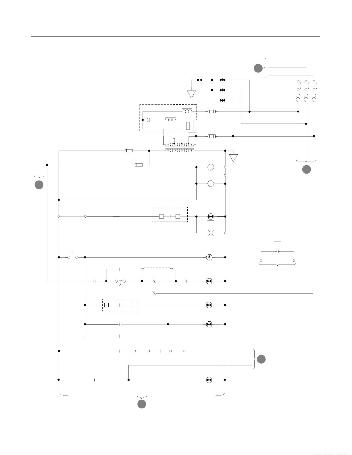
4-8 R3 and S3-Code Parallel Configurations
Figure 4.7
Schematics (cont.)
B
From RGU
AC Line
From RGU
Control
Circuitry
M2
F1
M1
F2
F3
From RGU
E
Control Power
Fault
F
Reset
CH1
CH2
CH3
S11
F2
F3
F4
AC
Rtn
Isolation
Board
TB5
1
Enable
2
Fault Reset
3
External Main
4
Common
R10, R10A
R11, R11A
R12, R12A
CH
F17
F18
F19
Bridge
Fan
CT1
CT2
Rs
Ss
Ts
0
6
2
2
1
1
-
-
-
1
1
1
J
J
J
SW1 Settings
For TB5-1, -2, -3
CT3
CT Power
Supply
CR
To
PE
Gnd
J7
P1
115VAC
OffX
24VDCOn
Burden Resistors
1
TB1
1
6
-
-
1
1
J
J
Publication 2364P-5.01 December 1999
To RGU
Control
Circuitry
To RGU
Control
Circuitry
TB6
1
3
4
6
8
9
Aux Control
Fault
Bus
Control
TB2
TB3
3
1
3
1
3
J2
Page 53

R3 and S3-Code Parallel Configurations 4-9
e
c
e
a
t
f
a
r
e
G
t
n
I
e
c
e
a
t
f
r
a
e
G
t
n
I
To System Networ k
C1
G
E1
C1
G
E1
J7
Main Bus
DC-DC
Converter
TP3
-t
J6
Bridge Thermal
Sensor (NTC)
J12
UP1
DETAIL
UP2
C1
G
E1
UN1
UN2
C1
G
E1
Gate Drivers
TP5
(+)
Horizontal
DC Bus
(-)
+
See U
r
Phase
e
b
b
Detail
u
n
S
VP1
VP2
See U
Phase
Detail
VN1
VN2
J8
F1
-15V+24V +15V
J2
J4
Blu
1
Shd
Shd
Clr
2
TP8TP4TP6
TP9
+12V+5V -12V
RIO Adapter Option
1
2
3
SW1
SW2
SW3
+24V
1203-GM1
R
J1
J8 J9
See U
r
Phase
e
b
b
Detail
u
n
S
WP1
WP2
See U
Phase
Detail
WN1
WN2
Gate Driver Board
24V
DC-DC
Converter
Aux 24V
Main Control Bo a rd
Y
YY
Off
On
Off
On
Off
On
J10
r
e
b
b
u
n
S
Cap
+15V
-15V
+5V
+12V
-12V
Bank
J10
J1
J3
J7
2
Power
B
T
Supply
Filter
1
Board
B
T
J11
TB7
P13
TB4
TB1
-
PE
TE
2
1
1
2
1
2
3
4
5
6
7
8
9
10
+Bus
-Bus
+
-
- Analog In 1
+ Analog In 1
Analog In 1 Common
- Analog In 2
+ Analog In 2
Analog In 2 Common
Analog Out 1
Analog Out 1 Common
Analog Out 2
Analog Out 2 Common
Horizontal DC Bus
To Inve rter Units
EA2
Bus Indicator Board
EA4
Bus Suppressor
LED1
LED2
PL1
R
DC Bus
Energized
RIO Ext SCANport 1 SCANport 2 R2R Comm
Publication 2364P-5.01 December 1999
Page 54

4-10 R3 and S3-Code Parallel Configurations
Publication 2364P-5.01 December 1999
Page 55

Chapter 5
R4 and S4-Code Parallel Configurations
R4-Code Parallel Configuration The R4-code parallel configur ation is a common DC bus front-end
unit consisting of an D-code NRU in parall el with an N-code RGU.
Figure 5.1
R4-Code Parallel Configuration–Information
R4-code Parallel ConfigurationR4-code Ratings
Input Voltage
(V AC)
380 1600
460
575
DC Bus Current
(A DC)
1600
1591
Rated DC Bus
kW
821
994
1235
D-code
NRU
N-code
RGU
S4-Code Parallel Configuration The S4-code parallel configuration is a common DC bus front-end
unit consisting of an E-code NRU in parallel with an N-code RGU.
Figure 5.2
S4-Code Parallel Configuration–Information
S4-code Parallel ConfigurationS4-code Ratings
Input Voltage
(V AC)
380 2100
460
575
DC Bus Current
(A DC)
2100
2091
Rated DC Bus
kW
1077
1304
1623
E-code
NRU
N-code
RGU
Note: Information for the D-code NRU and E-code NRU can be
found in publication 2364E-5.01. Information for the N-code
RGU can be found in publication 2364F-5.01.
Publication 2364P-5.01 December 1999
Page 56

5-2 R4 and S4-Code Parallel Configurations
9
Component Layout Figure 5.3
Enclosure Layout
Front View
101.25"
Shipping Split
Cutaway View
30" 30" 25" 35" 35"
Customer Supplied
AC Input Lines
20"
Feeder D-code NRU (1500A) or E-code NRU (2000A) N-code RGU
Publication 2364P-5.01 December 1999
Page 57

R4 and S4-Code Parallel Configurations 5-3
20" Overhead
Figure 5.4
Overhead Bus Assembly
Feeder
Splice Kit
To Feeder Buswork
30" Overhead
Bus Assembly
4" Bus Tabs
Flex Bus
Drop Tabs
To NRU circuit breaker
25" Overhead
Bus Assembly
Bus Assembly
Joiner-Splice Kits
New and Revised NRU and RGU Components in the R4 and S4 Configurations
NRU CB1 2000A, RD-frame with motor operator, aux contact (2NO/2NC)
EA10
F4, F6
PT1
TB10
Control power filter, 2kHz
Primary fuse for 5kVA control transformer
25A, KLDR (for 380V AC input)
20A, KLDR (for 460V AC input)
17.5A, KLDR (for 575V AC input)
Control power transformer, 5kVA
Control terminal block, 30A, 600V
Primary fuse for 10kVA control transformer (Opt 6P)
35A, KLDR (for 380V AC input)
30A, KLDR (for 460V AC input)
25A, KLDR (for 575V AC input)
Control power transformer, 10kVA (Opt 6P)
35" Overhead
Bus Assembly
End
Cap
2" Bus Tabs
Flex Bus
Drop Tabs
To RGU circuit breaker
RGU
CR3 Pilot Relay (2NO/2NC) with aux contact (1NO/1NC)
CR4
F4, F6
Precharge Lockout Relay (2NO/2NC)
Primary fuse for 5kVA transformer
25A, KLDR (for 380V AC input)
20A, KLDR (for 460V AC input)
17.5A, KLDR (for 575V AC input)
F21, F22
DC bus fuses, 500A, 700V, 170M
21A, 22A
F25
PT1
TR1
TB4
Fuse, NRU CB1 motor operator, 10A, KLDR
Control power transformer, 5kVA
Timer relay (3NO/1NC)
Control Terminal block, 30A, 600V
Overhead bus assembly
Publication 2364P-5.01 December 1999
Page 58

5-4 R4 and S4-Code Parallel Configurations
Schematics Figure 5.5
Schematics
NRU
TB1-1
Optional
Remote
Interlock
(JMPR)
TB1-2
Airflow Loss
Bridge Bay
1
EA5-CR
CB Bay
Overtemp
SP4
EA3
Line RC
Suppressor
Com
L1
L2
L3
SP1
F14
F15
F16
SP2
PE
SP3
2KHZ Control Power Filter
EA10
F4
F8
F7
(X1)
460VAC
115VAC
PT1
(X2)
MTR1
Rect. Bridge
MTR2
Choke Comp.
MTR3
CB Bay
CR2
Right
Choke
Overtemp
CH11-TG
CR1
Airflow Loss
3
CB Bay
13
EA6-CR
Heatsink
Overtemp
Left
Heatsink
Overtemp
F6
PE
TB1-9
TB1-10
Publication 2364P-5.01 December 1999
S3
Phase Loss
TB1-3
S1
To Ground Fault Detector
B
and Airflow Sensors
CR1
TB1-4 TB1-5 TB1-6
S2
Fault
CR2
Fault
PL2
A
Not
Faulted
1
L
C
A
V
0
2
1
115VAC
Control Bus To
Inverter Units
N
C
A
V
0
2
1
Page 59

R4 and S4-Code Parallel Configurations 5-5
Customer Supplied
3-phase Input
-Bus
Heat
Sink
D1
D3
CT1
F1 F2 F3
M
CB1- NRU
Note:
Control power for this
motorized breaker originates
in the RGU. Do not operate
this breaker manually.
AC Line
Current
AM1
F11
F12
F13
Heat
Sink
D2
D4
A
B
CR
C
+Bus
A
To RGU
AC Input
CR1
Phase
Loss
Relay
B
From NRU
Control Power
B
From NRU
Control Power
7
115VAC
ACN-ACL +
ACG
To Grounding
9
PS1
Resistor
Input
624
TB1-8
TB1-7
1012
Ground Fault
Detector
VM2
J2
3
To Cust omer
Monitoring Device
EA5
J2
In15
Sig 1
In26
+5 2
Com 3
J11
S5
Y
R
B
Flow
Sensor
D5
EA4
Bridge Suppressor
EA2
Bus Indicator PCB
+Bus
-Bus
(X4)
CH11 CH11
(X3)
DC Horizontal Bus To
LED1
LED2
VM1
DC Bus Voltage
Inverter Units
D6HS1 HS2
DC Bus
Energized
R
PL1
(X1)
(X2)
Publication 2364P-5.01 December 1999
Page 60

5-6 R4 and S4-Code Parallel Configurations
Figure 5.6
Schematics (cont.)
RGU
D
To
CB1-NRU
circuitry
TB1-1
Optional
Remote
Interlock
(JMPR)
RGU/DC Bus
Supply
Off On
S12
TB1-2
TR1
F7
Choke
Thermoguards
S1 - 3
CR4
TR1
EA10
F25
11
TB1
CR4
CR4
PE
2KHZ Control Power Filter
460VAC
(X1)
115VAC
F5
RGU Uni t Not
Faulted
14
TB6 TB6
Isolat i on Boa rd
12
TB1
CR3
SP4
(X2)
SP1
SP2
SP3
F4
F6
PT1
MTR6
Bay 1 Door Fan
MTR4,5
Bay 2 Fan
MTR1,2,3
RGU Door Fans
CR2
Fault
PL2
A
Not
Faulted
TR1
Precharge
Timer
M2
Precharge
TB1-9
TB1-10
(20 sec)
PE
From
3-phase
AC Input
A
G
To RGU
Precharge
Circuitry
TB1-5 TB1-6
CB1-RGU
CB2-RGU
Fault
CR2
Avail able for
Customer Use
C
To RGU Input
Fuses
6
TB6
CB1-RGU
TB3-7
CR3
CR3
Publication 2364P-5.01 December 1999
Bus Control
Isolation Board
CR3
CR4
TB3-8
TB3-7
TB3-10
9
TB6
TB4-4
CB1-RGU
E
CB1-NRU-A
TB10-7 TB10-8
UVR
To RGU
Control
Circuitry
TB4-5
TB3-8
TB3-9
TB3-11
TB3-12
CR3
Pilot
CR4
Precharge
Lockout
External Main
Enable
To RGU
F
Isolation Board
Page 61
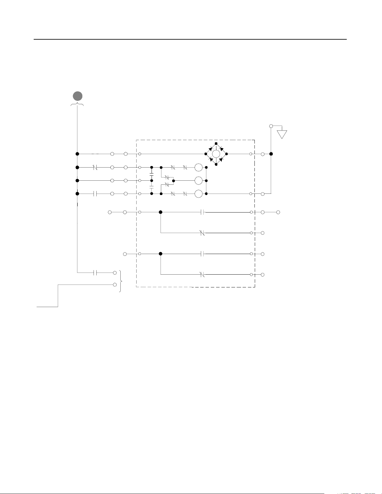
D
From RGU
Control Power
R4 and S4-Code Parallel Configurations 5-7
TB4-8
CB1-NRU
PE
TR1
CR3
TR1
Spring Windup
Wht/Red
TB4-6
TB10-1
Blu
TB4-9
TB10-3
TB4-7 TB10-4
TB4-3
TB10-5
TB10-7
TB4-4 TB4-5
Blk
Red
Blk
LS
X
Y
Y
Y
X
X
LS
M
Y
X
CB1-NRU-A
CB1-NRU-B
Blk
TB10-10
CB1-NRU-A
CB1-NRU-B
TB4-1
Not
Used
TB4-2
Open
Motor
Close
UVR
TB10-2
Wht
TB10-6
Red
TB10-8
Blu
TB10-9
Red
TB10-11
Blu
TB10-12
Publication 2364P-5.01 December 1999
Page 62

5-8 R4 and S4-Code Parallel Configurations
Figure 5.7
Schematics (cont.)
G
From
RGU-CB1
B
From RGU
AC Line
From RGU
Control
Circuitry
M2
F1
M1
F2
F3
From RGU
E
Control Power
Fault
F
Reset
CH1
CH2
CH3
S11
F2
F3
F4
AC
Rtn
Isolation
Board
TB5
1
Enable
2
Fault Reset
3
External Main
4
Common
R10, R10A
R11, R11A
R12, R12A
CH
F17
F18
F19
Bridge
Fan
CT1
CT2
Rs
Ss
Ts
0
6
2
2
1
1
-
-
-
1
1
1
J
J
J
SW1 Settings
For TB5-1, -2, -3
CT3
CT Power
Supply
CR
To
PE
Gnd
J7
P1
115VAC
OffX
24VDCOn
Burden Resistors
1
TB1
1
6
-
-
1
1
J
J
Publication 2364P-5.01 December 1999
To RGU
Control
Circuitry
To RGU
Control
Circuitry
TB6
1
3
4
6
8
9
Aux Control
Fault
Bus
Control
TB2
TB3
3
1
3
1
3
J2
Page 63

R4 and S4-Code Parallel Configurations 5-9
e
c
e
a
t
f
a
r
e
G
t
n
I
e
c
e
a
t
f
r
a
e
G
t
n
I
To System Networ k
C1
DETAIL
G
E1
C1
G
E1
J7
Main Bus
DC-DC
Converter
TP3
-t
J6
Bridge Thermal
Sensor (NTC)
J12
UP1
UP2
C1
G
E1
UN1
UN2
C1
G
E1
Gate Drivers
TP5
(+)
Horizontal
DC Bus
(-)
+
See U
r
Phase
e
b
b
Detail
u
n
S
VP1
VP2
See U
Phase
Detail
VN1
VN2
J8
F1
-15V+24V +15V
J2
J4
Blu
1
Shd
Shd
Clr
2
TP8TP4TP6
TP9
+12V+5V -12V
RIO Adapter Option
1
2
3
SW1
SW2
SW3
+24V
1203-GM1
R
J1
J8 J9
See U
r
Phase
e
b
b
Detail
u
n
S
WP1
WP2
See U
Phase
Detail
WN1
WN2
Gate Driver Board
24V
DC-DC
Converter
Aux 24V
Main Control Bo a rd
Y
YY
Off
On
Off
On
Off
On
J10
r
e
b
b
u
n
S
Cap
+15V
-15V
+5V
+12V
-12V
Bank
J10
J1
J3
J7
2
Power
B
T
Supply
Filter
1
Board
B
T
J11
TB7
P13
TB4
TB1
-
PE
TE
2
1
1
2
1
2
3
4
5
6
7
8
9
10
+Bus
-Bus
+
-
- Analog In 1
+ Analog In 1
Analog In 1 Common
- Analog In 2
+ Analog In 2
Analog In 2 Common
Analog Out 1
Analog Out 1 Common
Analog Out 2
Analog Out 2 Common
Horizontal DC Bus
To Inve rter Units
EA2
Bus Indicator Board
EA4
Bus Suppressor
LED1
LED2
PL1
R
DC Bus
Energized
RIO Ext SCANport 1 SCANport 2 R2R Comm
Publication 2364P-5.01 December 1999
Page 64

5-10 R4 and S4-Code Parallel Configurations
Publication 2364P-5.01 December 1999
Page 65

Chapter 6
T1 and V1-Code Parallel Configurations
T1-Code Parallel Configuration The T1-code paralle l configuration is a common DC bus front-end
unit consisting of an F-code NRU in paralle l with a K-code RGU.
Figure 6.1
T1-Code Parallel Configuration–Information
T1-code Parallel ConfigurationT1-code Ratings
Input Voltage
(V AC)
380 2520
460
575
DC Bus Current
(A DC)
2520
2520
Rated DC Bus
kW
1293
1565
1956
F-code
NRU
K-code
RGU
V1-Code Parallel Configuration The V1-code parallel configuration is a common DC bus front-end
unit consisting of an G-code NRU in parall el with a K-code RGU.
Figure 6.2
V1-Code Parallel Configuration–Information
V1-code Parallel ConfigurationV1-code Ratings
Input Voltage
(V AC)
380 3000
460
575
DC Bus Current
(A DC)
3000
3000
Rated DC Bus
kW
1539
1863
2329
G-code
NRU
K-code
RGU
Note: Information for the F-code NRU and G-code NRU can be
found in publication 2364E-5.01. Information for the K-code
RGU can be found in publication 2364F-5.01.
Publication 2364P-5.01 December 1999
Page 66

6-2 T1 and V1-Code Parallel Configurations
Component Layout Figure 6.3
Enclosure Layout
Front View
Shipping Split
101.25"
91.5"
Cutaway View
30" 30" 35" 25" 20"
Customer Supplied
AC Input Lines
Feeder F-code (2500A) or G-code (3000A) NRU K-code RGU
Publication 2364P-5.01 December 1999
Page 67

Figure 6.4
Overhead Bus Assembly
Feeder
Splice Kit
T1 and V1-Code Parallel Configurations 6-3
30" Overhead
Bus Assembly
End Cap
4" Bus Tabs
To Feeder Buswork
To NRU circuit breaker
Flex Bus
Drop Tabs
New and Revised NRU and RGU Components in the T1 and V1 Configurations
NRU CB1 (T1 config) 2500A, SPB-frame with motor operator
(V1 config) 3000A, SPB-frame with motor operator
RGU
EA10
F4, F6
PT1
TB10
CR4
F4, F6
F21, F22 DC bus fuses, 250A, 700V, 170M
F25
PT1
TR1
TB4
Control power filter, 4kHz
Primary fuse for 5kVA control transformer
25A, KLDR (for 380V AC input)
20A, KLDR (for 460V AC input)
17.5A, KLDR (for 575V AC input)
Control power transformer, 5kVA
Control terminal block, 30A, 600V
Precharge Lockout Relay (2NO/2NC)
Primary fuse for 2kVA transformer
10A, KLDR (for 380V AC input)
9A, KLDR (for 460V AC input)
8A, KLDR (for 575V AC input)
Fuse, NRU CB1 motor operator, 10A, KLDR
Control power transformer, 2kVA
Timer relay (3NO/1NC)
Control Terminal block, 30A, 600V
Primary fuse for 10kVA control transformer (Opt 6P)
35A, KLDR (for 380V AC input)
30A, KLDR (for 460V AC input)
25A, KLDR (for 575V AC input)
Control power transformer, 10kVA (Opt 6P)
The RGU AC line is connected to the
bus stubs on the NRU circuit breaker
Overhead bus assembly
Publication 2364P-5.01 December 1999
Page 68

6-4 T1 and V1-Code Parallel Configurations
Schematics Figure 6.5
Schematics
NRU
TB1-1
Optional
Remote
Interlock
(JMPR)
TB1-2
Airflow Loss
Bridge Bay
1
EA5-CR
CB Bay
Overtemp
SP4
EA3
Line RC
Suppressor
Com
L1
L2
L3
SP1
F14
F15
F16
SP2
PE
SP3
4KHZ Control Power Filter
EA10
F4
F8
F7
(X1)
460VAC
115VAC
PT1
(X2)
MTR1
Rect. Bridge
MTR2,3
Choke Comp.
MTR4,5,6
CB Bay
CR2
Right
Choke
Overtemp
CH11-TG
CR1
Airflow Loss
3
CB Bay
13
EA6-CR
Heatsink
Overtemp
Left
Heatsink
Overtemp
F6
PE
TB1-9
TB1-10
Publication 2364P-5.01 December 1999
S3
Phase Loss
TB1-3
S1
To Ground Fault Detector
B
and Airflow Sensors
CR1
TB1-4 TB1-5 TB1-6
S2
Fault
CR2
Fault
PL2
A
Not
Faulted
1
L
C
A
V
0
2
1
115VAC
Control Bus To
Inverter Units
N
C
A
V
0
2
1
Page 69

T1 and V1-Code Parallel Configurations 6-5
Customer Supplied
3-phase Input
-Bus
Heat
Sink
D1
D3
CT1
F1 F2 F3
M
CB1- NRU
Note:
Control power for this
motorized breaker originates
in the RGU. Do not operate
this breaker manually.
AC Line
Current
AM1
F11
F12
F13
Heat
Sink
D2
D4
A
B
CR
C
+Bus
A
To RGU
AC Input
CR1
Phase
Loss
Relay
B
From NRU
Control Power
B
From NRU
Control Power
7
115VAC
ACN-ACL +
ACG
To Grounding
9
PS1
Resistor
Input
624
TB1-8
TB1-7
1012
Ground Fault
Detector
VM2
J2
3
J2
3
To Cust omer
Monitoring Device
EA5
J2
In15
Sig 1
In26
+5 2
Com 3
J11
EA6
J2
In15
Sig 1
+5 2
In26
Com 3
J11
S5
Y
R
B
Flow
Sensor
S6
Y
R
B
Flow
Sensor
CH11
(X4)
(X3)
+Bus
-Bus
D5
EA2
EA4
Bus Indicator PCB
VM1
DC Bus Voltage
DC Horizontal Bus To
Inverter Units
Bridge Suppressor
LED1
LED2
D6HS1 HS2
DC Bus
Energized
R
PL1
(X1)
CH11
(X2)
Publication 2364P-5.01 December 1999
Page 70

6-6 T1 and V1-Code Parallel Configurations
Figure 6.6
Schematics (cont.)
RGU
D
To
CB1-NRU
circuitry
TB1-1
Optional
Remote
Interlock
(JMPR)
RGU/DC Bus
Supply
Off On
S12
TB1-2
TR1
CR4
TR1
From
A
3-phase
AC Input
CB1-RGU
4KHZ Control Power Filter
EA10
SP4
SP1
SP2
PE
SP3
F4
460VAC
F7
(X1)
115VAC
(X2)
F25
RGU Uni t Not
Faulted
14
TB6 TB6
Isolat i on Boa rd
F6
PT1
MTR1
RGU Door Fan
MTR2
RGU Door Fan
CR2
Fault
PL2
A
Not
Faulted
PE
TB1-9
TB1-10
Fault
C
To RGU Input
Fuses
CR2
TB1
TR1
Precharge
11
CR4
12
TB1
CR3
CR4
Timer
M2
Precharge
(20 sec)
TB1-5 TB1-6
Avail able f o r
Customer Use
6
TB6
CR3
Publication 2364P-5.01 December 1999
Bus Control
Isolation Board
CR3
CR4
M1
TB6
TB4-4
9
TB10-7
E
CB1-NRU-A
TB10-8
To RGU
Control
Circuitry
TB4-5
CR3
Pilot
CR4
Precharge
Lockout
M1
Main
External Main
Enable
F
Isolation Board
To RGU
Page 71

D
From RGU
Control Power
T1 and V1-Code Parallel Configurations 6-7
TB4-8
CB1-NRU
PE
TR1
TR1
TB4-1
Spring
Windup
TB4-2
CR3
TB4-3
TB4-4 TB10-7 TB4-5TB10-8
TB10-1
TB10-3
A12
Wht/Red
D9
Wht
D10
A6
A3
A1
B2
Digitrip
Blk
Blu
Org
Brn
SR
Spring
Release
Resistor When Required
(Not on 120 VAC)
Blk
Y
ARM
b
CB1-NRU-A
UVR
LC
Grn
SC
(Bot)
SC
CB1-NRU-B
CB1-NRU-A
TB10-10
B5
Blk
CB1-NRU-B
TB4-6
CB1-NRU-A
TB4-7
Not
Used
TB10-13
B8
Blk
CB1-NRU-B
TB4-9
CB1-NRU-A
TB10-16
B11
Blk
CB1-NRU-B
Red
Blu
Red
Blu
Red
Blu
Red
Blu
Red
A11
A2
B7
B9
B10
B12
TB10-2
TB10-5
B1
B3
TB10-9
B4
TB10-11
B6
TB10-12
TB10-14
Available For
Customer Use
TB10-15
TB10-17
TB10-18
Publication 2364P-5.01 December 1999
Page 72
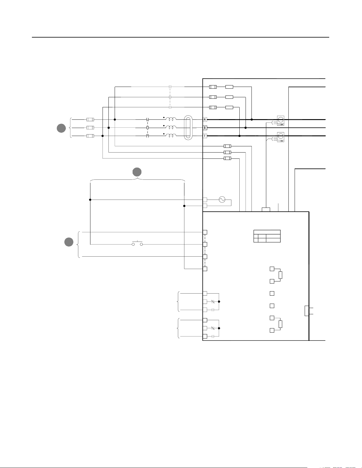
6-8 T1 and V1-Code Parallel Configurations
Figure 6.7
Schematics (cont.)
B
From RGU
AC Line
From RGU
Control
Circuitry
AC
Rtn
R10
F2
R11
F3
F4
R12
CT1
F17
F18
F19
Bridge
Fan
Rs
Ss
Ts
0
6
2
2
1
1
-
-
-
1
1
1
J
J
J
CT3
To
PE
Gnd
J7
P1
1
6
-
-
1
1
J
J
M2
CH11
F1
M1
F2
F3
From RGU
E
Control Power
CH1
CH2
CH3
Isolation
Board
TB5
1
Fault
F
Reset
S11
Enable
2
Fault Reset
3
External Main
4
Common
SW1 Settings
115VAC
OffX
24VDCOn
For TB5-1, -2, -3
Burden Resistors
1
TB1
Publication 2364P-5.01 December 1999
To RGU
Control
Circuitry
To RGU
Control
Circuitry
TB6
1
3
4
6
8
9
Aux Control
Fault
Bus
Control
TB2
TB3
3
1
TB2 Resistor
Not Required
3
1
3
J2
Page 73

T1 and V1-Code Parallel Configurations 6-9
d
r
a
o
B
r
e
b
b
u
n
S
To System Network
UP
C1
G
E1
UN
C1
G
E1
J7
Main Bus
DC-DC
Converter
TP3
-t
J6
Bridge Thermal
Sensor (NTC)
J12
Gate Drivers
TP5
-15V+24V +15V
Shd
(+)
Horizontal
DC Bus
(-)
F1
G
G
24V
DC-DC
Aux 24V
J10
WP
C1
E1
Cap
Bank
WN
C1
E1
J10
+15V
-15V
+5V
+12V
-12V
J1
J3
J7
d
r
a
o
B
G
r
e
b
E1
b
u
n
S
VN
C1
G
E1
J8
F1
d
r
a
o
B
r
e
b
b
u
n
S
Gate Driver Board
+24V
VP
C1
Converter
TP8TP4TP6
TP9
+12V+5V -12V
Main Control Bo a rd
J2
RIO Adapter Option
1
1203-GM1
2
3
Y
R
YY
SW1
SW2
J4
Blu
1
SW3
Shd
Clr
2
OF
F
O
N
OF
F
O
N
OF
F
O
N
J1
J8 J9
2
Power
B
T
Supply
Filter
1
Board
B
T
J11
TB7
P13
TB4
TB1
+
-
PE
TE
2
1
1
2
1
2
3
4
5
6
7
8
9
10
+Bus
-Bus
+
-
- Analog In 1
+ Analog In 1
Analog In 1 Common
- Analog In 2
+ Analog In 2
Analog In 2 Common
Analog Out 1
Analog Out 1 Common
Analog Out 2
Analog Out 2 Common
Horizontal DC Bus
To Inve rter Units
EA2
Bus Indicator Board
EA4
Bus Suppressor
LED1
LED2
PL1
R
DC Bus
Energized
RIO Ext SCANport 1 SCANport 2 R2R Comm
Publication 2364P-5.01 December 1999
Page 74

6-10 T1 and V1-Code Parallel Configurations
Publication 2364P-5.01 December 1999
Page 75

Chapter 7
T2 and V2-Code Parallel Configurations
T2-Code Parallel Configuration The T2-code paralle l configuration is a common DC bus front-end
unit consisting of an F-code NRU in paralle l with a L-code RGU.
Figure 7.1
T2-Code Parallel Configuration–Information
T2-code Parallel ConfigurationT2-code Ratings
Input Voltage
(V AC)
380 2536
460
575
DC Bus Current
(A DC)
2536
2536
Rated DC Bus
kW
1301
1575
1966
F-code
NRU
L-code
RGU
V2-Code Parallel Configuration The V2-code parallel configuration is a common DC bus front-end
unit consisting of an G-code NRU in parall el with a L-code RGU.
Figure 7.2
V2-Code Parallel Configuration–Information
V2-code Parallel ConfigurationV2-code Ratings
Input Voltage
(V AC)
380 3000
460
575
DC Bus Current
(A DC)
3000
3000
Rated DC Bus
kW
1539
1863
2329
G-code
NRU
L-code
RGU
Note: Information for the F-code NRU and G-code NRU can be
found in publication 2364E-5.01. Information for the L-code
RGU can be found in publication 2364F-5.01.
Publication 2364P-5.01 December 1999
Page 76

7-2 T2 and V2-Code Parallel Configurations
Component Layout Figure 7.3
Enclosure Layout
Front View
Shipping Split
101.25"
91.5"
30" 25"30" 30" 35"
Cutaway View
Customer Supplied
AC Input Lines
Feeder F-code (2500A) or G-code (3000A) NRU
L-code RGU
Publication 2364P-5.01 December 1999
Page 77

Figure 7.4
Overhead Bus Assembly
Feeder
Splice Kit
T2 and V2-Code Parallel Configurations 7-3
30" Overhead
Bus Assembly
End Cap
4" Bus Tabs
To Feeder Buswork
To NRU circuit breaker
Flex Bus
Drop Tabs
New and Revised NRU and RGU Components in the T2 and V2 Configurations
NRU CB1 (T1 config) 2500A, SPB-frame with motor operator
(V1 config) 3000A, SPB-frame with motor operator
RGU
EA10
F4, F6
PT1
TB10
CR4
F4, F6
F21, F22 DC bus fuses, 500A, 700V, 170M
F25
PT1
TR1
TB4
Control power filter, 2kHz
Primary fuse for 5kVA control transformer
25A, KLDR (for 380V AC input)
20A, KLDR (for 460V AC input)
17.5A, KLDR (for 575V AC input)
Control power transformer, 5kVA
Control terminal block, 30A, 600V
Precharge Lockout Relay (2NO/2NC)
Primary fuse for 5kVA transformer
25A, KLDR (for 380V AC input)
20A, KLDR (for 460V AC input)
17.5A, KLDR (for 575V AC input)
Fuse, NRU CB1 motor operator, 10A, KLDR
Control power transformer, 5kVA
Timer relay (3NO/1NC)
Control Terminal block, 30A, 600V
Primary fuse for 10kVA control transformer (Opt 6P)
35A, KLDR (for 380V AC input)
30A, KLDR (for 460V AC input)
25A, KLDR (for 575V AC input)
Control power transformer, 10kVA (Opt 6P)
The RGU AC line is connected to the
bus stubs on the NRU circuit breaker
Overhead bus assembly
Publication 2364P-5.01 December 1999
Page 78

7-4 T2 and V2-Code Parallel Configurations
Schematics Figure 7.5
Schematics
NRU
TB1-1
Optional
Remote
Interlock
(JMPR)
TB1-2
Airflow Loss
Bridge Bay
1
EA5-CR
CB Bay
Overtemp
SP4
EA3
Line RC
Suppressor
Com
L1
L2
L3
SP1
F14
F15
F16
SP2
PE
SP3
2KHZ Control Power Filter
EA10
F4
F8
F7
(X1)
460VAC
115VAC
PT1
(X2)
MTR1
Rect. Bridge
MTR2,3
Choke Comp.
MTR4,5,6
CB Bay
CR2
Right
Choke
Overtemp
CH11-TG
CR1
Airflow Loss
3
CB Bay
13
EA6-CR
Heatsink
Overtemp
Left
Heatsink
Overtemp
F6
PE
TB1-9
TB1-10
Publication 2364P-5.01 December 1999
S3
Phase Loss
TB1-3
S1
To Ground Fault Detector
B
and Airflow Sensors
CR1
TB1-4 TB1-5 TB1-6
S2
Fault
CR2
Fault
PL2
A
Not
Faulted
1
L
C
A
V
0
2
1
115VAC
Control Bus To
Inverter Units
N
C
A
V
0
2
1
Page 79

T2 and V2-Code Parallel Configurations 7-5
Customer Supplied
3-phase Input
-Bus
Heat
Sink
D1
D3
CT1
F1 F2 F3
M
CB1- NRU
Note:
Control power for this
motorized breaker originates
in the RGU. Do not operate
this breaker manually.
AC Line
Current
AM1
F11
F12
F13
Heat
Sink
D2
D4
A
B
CR
C
+Bus
A
To RGU
AC Input
CR1
Phase
Loss
Relay
B
From NRU
Control Power
B
From NRU
Control Power
7
115VAC
ACN-ACL +
ACG
To Grounding
9
PS1
Resistor
Input
624
TB1-8
TB1-7
1012
Ground Fault
Detector
VM2
J2
3
J2
3
To Cust omer
Monitoring Device
EA5
J2
In15
Sig 1
In26
+5 2
Com 3
J11
EA6
J2
In15
Sig 1
+5 2
In26
Com 3
J11
S5
Y
R
B
Flow
Sensor
S6
Y
R
B
Flow
Sensor
D5
EA4
Bridge Suppressor
EA2
Bus Indicator PCB
+Bus
-Bus
(X4)
CH11 CH11
(X3)
DC Horizontal Bus To
LED1
LED2
VM1
DC Bus Voltage
Inverter Units
D6HS1 HS2
DC Bus
Energized
R
PL1
(X1)
(X2)
Publication 2364P-5.01 December 1999
Page 80

7-6 T2 and V2-Code Parallel Configurations
Figure 7.6
Schematics (cont.)
RGU
D
To
CB1-NRU
circuitry
TB1-1
Optional
Remote
Interlock
(JMPR)
RGU/DC Bus
Supply
Off On
S12
TB1-2
TR1
CR4
TR1
From
A
3-phase
AC Input
CB1-RGU
2KHZ Control Power Filter
EA10
SP4
SP1
SP2
PE
SP3
F4
460VAC
F7
(X1)
115VAC
(X2)
F25
RGU Uni t Not
Faulted
14
TB6 TB6
Isolat i on Boa rd
F6
PT1
MTR1,2
Bay Door Fans
MTR3,4
Bay 1 Door Fans
CR2
Fault
PL2
A
Not
Faulted
PE
TB1-9
TB1-10
Fault
C
To RGU Input
Fuses
CR2
TB1
TR1
Precharge
11
CR4
12
TB1
CR3
CR4
Timer
M2
Precharge
(20 sec)
TB1-5 TB1-6
Avail able f o r
Customer Use
6
TB6
CR3
Publication 2364P-5.01 December 1999
Bus Control
Isolation Board
CR3
CR4
M1
TB6
TB4-4
9
TB10-7
E
CB1-NRU-A
To RGU
Control
Circuitry
TB10-8
TB4-5
CR3
Pilot
CR4
Precharge
Lockout
M1
Main
External M ain
Enable
F
Isolation Board
To RGU
Page 81
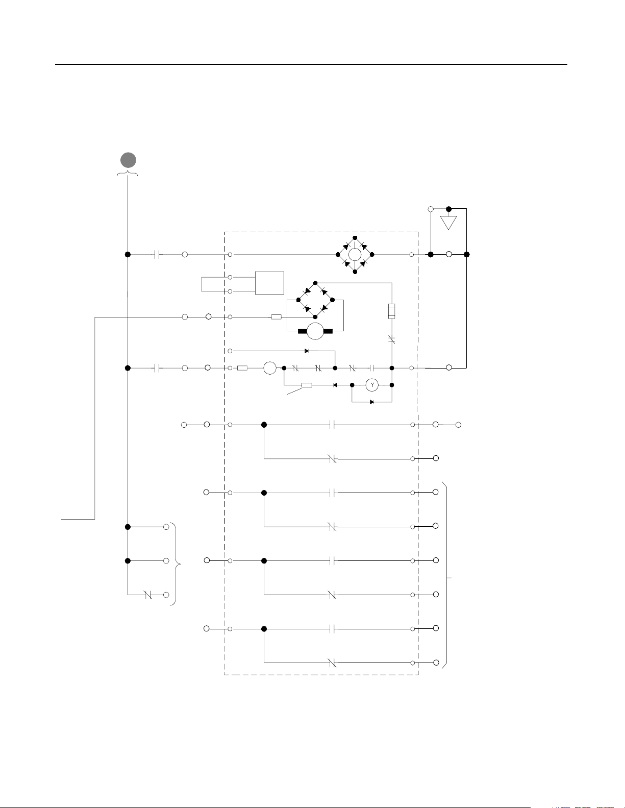
D
From RGU
Control Power
T2 and V2-Code Parallel Configurations 7-7
TB4-8
CB1-NRU
PE
TR1
TR1
TB4-1
Spring
Windup
TB4-2
CR3
TB4-3
TB4-4 TB10-7 TB4-5TB10-8
TB10-1
TB10-3
A12
Wht/Red
D9
Wht
D10
A6
A3
A1
B2
Digitrip
Blk
Blu
Org
Brn
SR
Spring
Release
Resistor When Required
(Not on 120 VAC)
Blk
Y
ARM
b
CB1-NRU-A
UVR
LC
Grn
SC
(Bot)
SC
CB1-NRU-B
CB1-NRU-A
TB10-10
B5
Blk
CB1-NRU-B
TB4-6
CB1-NRU-A
TB4-7
Not
Used
TB10-13
B8
Blk
CB1-NRU-B
TB4-9
CB1-NRU-A
TB10-16
B11
Blk
CB1-NRU-B
Red
Blu
Red
Blu
Red
Blu
Red
Blu
Red
A11
B10
B12
TB10-2
A2
TB10-5
B1
B3
TB10-9
B4
TB10-11
B6
TB10-12
B7
TB10-14
Available For
B9
Customer Use
TB10-15
TB10-17
TB10-18
Publication 2364P-5.01 December 1999
Page 82

7-8 T2 and V2-Code Parallel Configurations
Figure 7.7
Schematics (cont.)
B
From RGU
AC Line
From RGU
Control
Circuitry
AC
Rtn
R10
F2
R11
F3
F4
R12
CT1
F17
F18
F19
Bridge
Fan
Rs
Ss
Ts
0
6
2
2
1
1
-
-
-
1
1
1
J
J
J
CT3
To
PE
Gnd
J7
P1
1
6
-
-
1
1
J
J
M2
F1
M1
F2
F3
From RGU
E
Control Power
CH1
CH2
CH3
CH11
Isolation
Board
TB5
1
Fault
F
Reset
S11
Enable
2
Fault Reset
3
External Main
4
Common
SW1 Settings
115VAC
OffX
24VDCOn
For TB5-1, -2, -3
Burden Resistors
1
TB1
Publication 2364P-5.01 December 1999
To RGU
Control
Circuitry
To RGU
Control
Circuitry
TB6
1
3
4
6
8
9
Aux Control
Fault
Bus
Control
TB2
TB3
3
1
TB2 Resisto r
Not Required
3
1
3
J2
Page 83

T2 and V2-Code Parallel Configurations 7-9
e
c
e
a
t
f
a
r
e
G
t
n
I
e
c
e
a
t
f
r
a
e
G
t
n
I
To System Network
C1
G
E1
C1
G
E1
J7
Main Bus
DC-DC
Converter
TP3
-t
J6
Bridge Thermal
Sensor (NTC)
J12
UP
DETAIL
UN
Gate Drivers
TP5
-15V+24V +15V
Shd
(+)
Horizontal
DC Bus
(-)
F1
See U
r
Phase
e
b
b
Detail
u
n
S
VP
See U
Phase
Detail
VN
J8
F1
J2
J4
Blu
1
Shd
Clr
2
TP8TP4TP6
TP9
+12V+5V -12V
RIO Adapter Option
1
2
3
SW1
SW2
SW3
+24V
1203-GM1
R
J1
J8 J9
See U
r
Phase
e
b
b
Detail
u
n
S
WP
See U
Phase
Detail
WN
Gate Driver Board
24V
DC-DC
Converter
Aux 24V
Main Control Bo a rd
Y
YY
Off
On
Off
On
Off
On
J10
r
e
b
b
u
n
S
Cap
Bank
J10
+15V
-15V
+5V
+12V
-12V
J1
J3
J7
2
Power
B
T
Supply
Filter
1
Board
B
T
J11
TB7
P13
TB4
TB1
+
-
PE
TE
2
1
1
2
1
2
3
4
5
6
7
8
9
10
+Bus
-Bus
+
-
- Analog In 1
+ Analog In 1
Analog In 1 Common
- Analog In 2
+ Analog In 2
Analog In 2 Common
Analog Out 1
Analog Out 1 Common
Analog Out 2
Analog Out 2 Common
Horizontal DC Bus
To Inve rter Units
EA2
Bus Indicator Board
EA4
Bus Suppressor
LED1
LED2
PL1
R
DC Bus
Energized
RIO Ext SCANport 1 SCANport 2 R2R Comm
Publication 2364P-5.01 December 1999
Page 84

7-10 T2 and V2-Code Parallel Configurations
Publication 2364P-5.01 December 1999
Page 85

Chapter 8
T3 and V3-Code Parallel Configurations
T3-Code Parallel Configuration The T3-code paralle l configuration is a common DC bus front-end
unit consisting of an F-code NRU in paralle l with a M-code RGU.
Figure 8.1
T3-Code Parallel Configuration–Information
T3-code Parallel ConfigurationT3-code Ratings
Input Voltage
(V AC)
380 2575
460
575
DC Bus Current
(A DC)
2575
2575
Rated DC Bus
kW
1321
1599
1994
F-code
NRU
M-code
RGU
V3-Code Parallel Configuration The V3-code parallel configuration is a common DC bus front-end
unit consisting of an G-code NRU in parall el with a M-code RGU.
Figure 8.2
V3-Code Parallel Configuration–Information
V3-code Parallel ConfigurationV3-code Ratings
Input Voltage
(V AC)
380 3000
460
575
DC Bus Current
(A DC)
3000
3000
Rated DC Bus
kW
1539
1863
2329
G-code
NRU
M-code
RGU
Note: Information for the F-code NRU and G-code NRU can be
found in publication 2364E-5.01. Information for the M-code
RGU can be found in publication 2364F-5.01.
Publication 2364P-5.01 December 1999
Page 86

8-2 T3 and V3-Code Parallel Configurations
Component Layout Figure 8.3
Enclosure Layout
Front View
101.25"
30" 30" 35"
Shipping Split
91.5"
35" 35"
Cutaway View
Customer Supplied
AC Input Lines
Feeder F-code (2500A) or G-code (3000A) NRU
M-code RGU
Publication 2364P-5.01 December 1999
Page 87

T3 and V3-Code Parallel Configurations 8-3
Figure 8.4
Overhead Bus Assembly
Feeder
Splice Kit
To Feeder Buswork
30" Overhead
Bus Assembly
4" Bus Tabs
Flex Bus
Drop Tabs
To NRU circuit breaker
35" Overhead
Bus Assembly
Joiner-Splice Kits
New and Revised NRU and RGU Components in the T3 and V3 Configurations
NRU CB1 (T1 config) 2500A, SPB-frame with motor operator
(V1 config) 3000A, SPB-frame with motor operator
EA10
F4, F6
PT1
TB10
Control power filter, 2kHz
Primary fuse for 5kVA control transformer
25A, KLDR (for 380V AC input)
20A, KLDR (for 460V AC input)
17.5A, KLDR (for 575V AC input)
Control power transformer, 5kVA
Control terminal block, 30A, 600V
35" Overhead
Bus Assembly
End
Cap
2" Bus Tabs
Flex Bus
Drop Tabs
To RGU circuit breaker
Primary fuse for 10kVA control transformer (Opt 6P)
35A, KLDR (for 380V AC input)
30A, KLDR (for 460V AC input)
25A, KLDR (for 575V AC input)
Control power transformer, 10kVA (Opt 6P)
RGU
CR4
F4, F6
Precharge Lockout Relay (2NO/2NC)
Primary fuse for 5kVA transformer
25A, KLDR (for 380V AC input)
20A, KLDR (for 460V AC input)
17.5A, KLDR (for 575V AC input)
F21, F22 DC bus fuses, 500A, 700V, 170M
21A, 22A
F25
PT1
TR1
Fuse, NRU CB1 motor operator, 10A, KLDR
Control power transformer, 5kVA
Timer relay (3NO/1NC)
TB4 Control Terminal block, 30A, 600V
Overhead bus assembly
Publication 2364P-5.01 December 1999
Page 88

8-4 T3 and V3-Code Parallel Configurations
Schematics Figure 8.5
Schematics
NRU
TB1-1
Optional
Remote
Interlock
(JMPR)
TB1-2
Airflow Loss
Bridge Bay
1
EA5-CR
CB Bay
Overtemp
SP4
EA3
Line RC
Suppressor
Com
L1
L2
L3
SP1
F14
F15
F16
SP2
PE
SP3
2KHZ Control Power Filter
EA10
F4
F8
F7
(X1)
460VAC
115VAC
PT1
(X2)
MTR1
Rect. Bridge
MTR2,3
Choke Comp.
MTR4,5,6
CB Bay
CR2
Right
Choke
Overtemp
CH11-TG
CR1
Airflow Loss
3
CB Bay
13
EA6-CR
Heatsink
Overtemp
Left
Heatsink
Overtemp
F6
PE
TB1-9
TB1-10
Publication 2364P-5.01 December 1999
S3
Phase Loss
TB1-3
S1
To Ground Fault Detector
B
and Airflow Sensors
CR1
TB1-4 TB1-5 TB1-6
S2
Fault
CR2
Fault
PL2
A
Not
Faulted
1
L
C
A
V
0
2
1
115VAC
Control Bus To
Inverter Units
N
C
A
V
0
2
1
Page 89
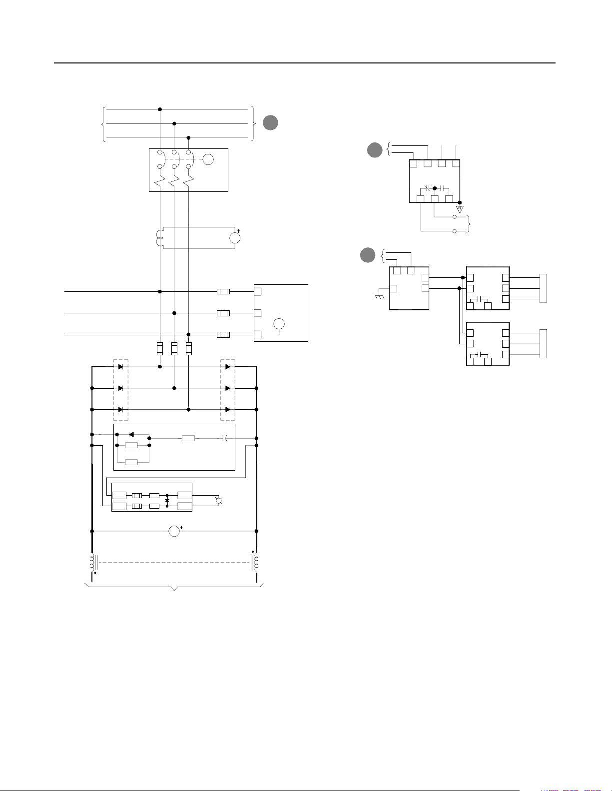
T3 and V3-Code Parallel Configurations 8-5
Customer Supplied
3-phase Input
-Bus
Heat
Sink
D1
D3
CT1
F1 F2 F3
M
CB1- NRU
Note:
Control power for this
motorized breaker originates
in the RGU. Do not operate
this breaker manually.
AC Line
Current
AM1
F11
F12
F13
Heat
Sink
D2
D4
A
B
CR
C
+Bus
A
To RGU
AC Input
CR1
Phase
Loss
Relay
B
From NRU
Control Power
B
From NRU
Control Power
7
115VAC
ACN-ACL +
ACG
To Grounding
9
PS1
Resistor
Input
624
TB1-8
TB1-7
1012
Ground Fault
Detector
VM2
J2
3
J2
3
To Cust omer
Monitoring Device
EA5
J2
In15
Sig 1
In26
+5 2
Com 3
J11
EA6
J2
In15
Sig 1
+5 2
In26
Com 3
J11
S5
Y
R
B
Flow
Sensor
S6
Y
R
B
Flow
Sensor
D5
EA4
Bridge Suppressor
EA2
Bus Indicator PCB
+Bus
-Bus
(X4)
CH11 CH11
(X3)
DC Horizontal Bus To
LED1
LED2
VM1
DC Bus Voltage
Inverter Units
D6HS1 HS2
DC Bus
Energized
R
PL1
(X1)
(X2)
Publication 2364P-5.01 December 1999
Page 90

8-6 T3 and V3-Code Parallel Configurations
Figure 8.6
Schematics (cont.)
RGU
D
To
CB1-NRU
circuitry
TB1-1
Optional
Remote
Interlock
(JMPR)
RGU/DC Bus
Supply
Off On
S12
TB1-2
TR1
F7
Choke
Thermoguards
S1 - 3
CR4
TR1
EA10
F25
11
TB1
CR4
CR4
2KHZ Control Power Filter
460VAC
(X1)
115VAC
RGU Uni t Not
Faulted
14
TB6 TB6
Isolat i on Boa rd
12
TB1
CR3
SP4
PE
PT1
(X2)
Bay 1 Door Fan
Bay 1 Internal Fan
RGU Door Fans
Precharge
Precharge
F4
F6
MTR2
MTR3
MTR1
CR2
Fault
PL2
A
Not
Faulted
TR1
Timer
M2
SP1
SP2
SP3
PE
TB1-9
TB1-10
(20 sec)
From
3-phase
AC Input
A
Fault
CR2
TB1-5 TB1-6
Avail able f o r
Customer Use
CB1-RGU
C
To RGU Input
Fuses
6
TB6
CR3
Publication 2364P-5.01 December 1999
Bus Control
Isolation Board
CR3
CR4
M1
TB6
TB4-4
9
TB10-7
E
CB1-NRU-A
To RGU
Control
Circuitry
TB10-8
TB4-5
CR3
Pilot
CR4
Precharge
Lockout
M1
Main
External M ain
Enable
F
Isolation Board
To RGU
Page 91

D
Control Power
From RGU
T3 and V3-Code Parallel Configurations 8-7
TB4-8
CB1-NRU
PE
TR1
TR1
TB4-1
Spring
Windup
TB4-2
CR3
TB4-3
TB4-4 TB10-7 TB4-5TB10-8
TB10-1
TB10-3
A12
Wht/Red
D9
Wht
D10
A6
A3
A1
B2
Digitrip
Blk
Blu
Org
Brn
SR
Spring
Release
Resistor When Required
(Not on 120 VAC)
Blk
Y
ARM
b
CB1-NRU-A
UVR
LC
Grn
SC
(Bot)
SC
CB1-NRU-B
CB1-NRU-A
TB10-10
B5
Blk
CB1-NRU-B
TB4-6
CB1-NRU-A
TB4-7
Not
Used
TB10-13
B8
Blk
CB1-NRU-B
TB4-9
CB1-NRU-A
TB10-16
B11
Blk
CB1-NRU-B
Red
Blu
Red
Blu
Red
Blu
Red
Blu
Red
A11
B10
B12
TB10-2
A2
TB10-5
B1
B3
TB10-9
B4
TB10-11
B6
TB10-12
B7
TB10-14
Available For
B9
Customer Use
TB10-15
TB10-17
TB10-18
Publication 2364P-5.01 December 1999
Page 92

8-8 T3 and V3-Code Parallel Configurations
Figure 8.7
Schematics (cont.)
B
From RGU
AC Line
From RGU
Control
Circuitry
M2
F1
M1
F2
F3
From RGU
E
Control Power
Fault
F
Reset
CH1
CH2
CH3
S11
F2
F3
F4
AC
Rtn
Isolation
Board
TB5
1
Enable
2
Fault Reset
3
External Main
4
Common
R10, R10A
R11, R11A
R12, R12A
CH
F17
F18
F19
Bridge
Fan
CT1
CT2
Rs
Ss
Ts
0
6
2
2
1
1
-
-
-
1
1
1
J
J
J
SW1 Settings
For TB5-1, -2, -3
CT3
CT Power
Supply
CR
To
PE
Gnd
J7
P1
115VAC
OffX
24VDCOn
Burden Resistors
1
TB1
1
6
-
-
1
1
J
J
Publication 2364P-5.01 December 1999
To RGU
Control
Circuitry
To RGU
Control
Circuitry
TB6
1
3
4
6
8
9
Aux Control
Fault
Bus
Control
TB2
TB3
3
1
3
1
3
J2
Page 93

T3 and V3-Code Parallel Configurations 8-9
e
c
e
a
t
f
a
r
e
G
t
n
I
e
c
e
a
t
f
r
a
e
G
t
n
I
To System Networ k
C1
DETAIL
G
E1
C1
G
E1
J7
Main Bus
DC-DC
Converter
TP3
-t
J6
Bridge Thermal
Sensor (NTC)
J12
UP1
UP2
C1
G
E1
UN1
UN2
C1
G
E1
Gate Drivers
TP5
(+)
Horizontal
DC Bus
(-)
+
See U
r
Phase
e
b
b
Detail
u
n
S
VP1
VP2
See U
Phase
Detail
VN1
VN2
J8
F1
-15V+24V +15V
J2
J4
Blu
1
Shd
Shd
Clr
2
TP8TP4TP6
TP9
+12V+5V -12V
RIO Adapter Option
1
2
3
SW1
SW2
SW3
+24V
1203-GM1
R
J1
J8 J9
See U
r
Phase
e
b
b
Detail
u
n
S
WP1
WP2
See U
Phase
Detail
WN1
WN2
Gate Driver Board
24V
DC-DC
Converter
Aux 24V
Main Control Bo a rd
Y
YY
Off
On
Off
On
Off
On
J10
r
e
b
b
u
n
S
Cap
+15V
-15V
+5V
+12V
-12V
Bank
J10
J1
J3
J7
2
Power
B
T
Supply
Filter
1
Board
B
T
J11
TB7
P13
TB4
TB1
-
PE
TE
2
1
1
2
1
2
3
4
5
6
7
8
9
10
+Bus
-Bus
+
-
- Analog In 1
+ Analog In 1
Analog In 1 Common
- Analog In 2
+ Analog In 2
Analog In 2 Common
Analog Out 1
Analog Out 1 Common
Analog Out 2
Analog Out 2 Common
Horizontal DC Bus
To Inve rter Units
EA2
Bus Indicator Board
EA4
Bus Suppressor
LED1
LED2
PL1
R
DC Bus
Energized
RIO Ext SCANport 1 SCANport 2 R2R Comm
Publication 2364P-5.01 December 1999
Page 94

8-10 T3 and V3-Code Parallel Configurations
Publication 2364P-5.01 December 1999
Page 95

Chapter 9
T4 and V4-Code Parallel Configurations
T4-Code Parallel Configuration The T4-code paralle l configuration is a common DC bus front-end
unit consisting of an F-code NRU in paralle l with a N-code RGU.
Figure 9.1
T4-Code Parallel Configuration–Information
T4-code Parallel ConfigurationT4-code Ratings
Input Voltage
(V AC)
380 2600
460
575
DC Bus Current
(A DC)
2600
2591
Rated DC Bus
kW
1334
1615
2012
F-code
NRU
N-code
RGU
V4-Code Parallel Configuration The V4-code parallel configuration is a common DC bus front-end
unit consisting of an G-code NRU in parall el with a N-code RGU.
Figure 9.2
V4-Code Parallel Configuration–Information
V4-code Parallel ConfigurationV4-code Ratings
Input Voltage
(V AC)
380 3000
460
575
DC Bus Current
(A DC)
3000
3000
Rated DC Bus
kW
1539
1863
2329
G-code
NRU
N-code
RGU
Note: Information for the F-code NRU and G-code NRU can be
found in publication 2364E-5.01. Information for the N-code
RGU can be found in publication 2364F-5.01.
Publication 2364P-5.01 December 1999
Page 96

9-2 T4 and V4-Code Parallel Configurations
Component Layout Figure 9.3
Enclosure Layout
Front View
101.25"
30" 30" 35"
Shipping Split
20"
91.5"
35" 35"
Cutaway View
Customer Supplied
AC Input Lines
Feeder F-code (2500A) or G-code (3000A) NRU
N-code RGU
Publication 2364P-5.01 December 1999
Page 97

T4 and V4-Code Parallel Configurations 9-3
20" Overhead
Figure 9.4
Overhead Bus Assembly
Feeder Splice
Assembly
To Feeder Buswork
30" Overhead
Bus Assembly
4" Bus Tabs
Flex Bus
Drop Tabs
To NRU circuit breaker
35" Overhead
Bus Assembly
Bus Assembly
Joiner-Splice
Assemblies
New and Revised NRU and RGU Components in the T4 and V4 Configurations
NRU CB1
EA10
F4, F6
PT1
TB10
(T1 config) 2500A, SPB-frame with motor operator
(V1 config) 3000A, SPB-frame with motor operator
Control power filter, 2kHz
Primary fuse for 5kVA control transformer
25A, KLDR (for 380V AC input)
20A, KLDR (for 460V AC input)
17.5A, KLDR (for 575V AC input)
Control power transformer, 5kVA
Control terminal block, 30A, 600V
Primary fuse for 10kVA control transformer (Opt 6P)
35A, KLDR (for 380V AC input)
30A, KLDR (for 460V AC input)
25A, KLDR (for 575V AC input)
Control power transformer, 10kVA (Opt 6P)
35" Overhead
Bus Assembly
End
Cap
2" Bus Tabs
Flex Bus
Drop Tabs
To RGU circuit breaker
RGU
CR3 Pilot relay (2NO/2NC) with aux contact (1NO/1NC)
CR4
F4, F6
Precharge Lockout Relay (2NO/2NC)
Primary fuse for 5kVA transformer
25A, KLDR (for 380V AC input)
20A, KLDR (for 460V AC input)
17.5A, KLDR (for 575V AC input)
F21, F22 DC bus fuses, 500A, 700V, 170M
21A, 22A
F25
PT1
TR1
Fuse, NRU CB1 motor operator, 10A, KLDR
Control power transformer, 5kVA
Timer relay (3NO/1NC)
TB4 Control Terminal block, 30A, 600V
Overhead bus assembly
Publication 2364P-5.01 December 1999
Page 98

9-4 T4 and V4-Code Parallel Configurations
Schematics Figure 9.5
Schematics
NRU
TB1-1
Optional
Remote
Interlock
(JMPR)
TB1-2
Airflow Loss
Bridge Bay
1
EA5-CR
CB Bay
Overtemp
SP4
EA3
Line RC
Suppressor
Com
L1
L2
L3
SP1
F14
F15
F16
SP2
PE
SP3
2KHZ Control Power Filter
EA10
F4
F8
F7
(X1)
460VAC
115VAC
PT1
(X2)
MTR1
Rect. Bridge
MTR2,3
Choke Comp.
MTR4,5,6
CB Bay
CR2
Right
Choke
Overtemp
CH11-TG
CR1
Airflow Loss
3
CB Bay
13
EA6-CR
Heatsink
Overtemp
Left
Heatsink
Overtemp
F6
PE
TB1-9
TB1-10
Publication 2364P-5.01 December 1999
S3
Phase Loss
TB1-3
S1
To Ground Fault Detector
B
and Airflow Sensors
CR1
TB1-4 TB1-5 TB1-6
S2
Fault
CR2
Fault
PL2
A
Not
Faulted
1
L
C
A
V
0
2
1
115VAC
Control Bus To
Inverter Units
N
C
A
V
0
2
1
Page 99

T4 and V4-Code Parallel Configurations 9-5
Customer Supplied
3-phase Input
-Bus
Heat
Sink
D1
D3
CT1
F1 F2 F3
M
CB1- NRU
Note:
Control power for this
motorized breaker originates
in the RGU. Do not operate
this breaker manually.
AC Line
Current
AM1
F11
F12
F13
Heat
Sink
D2
D4
A
B
CR
C
+Bus
A
To RGU
AC Input
CR1
Phase
Loss
Relay
B
From NRU
Control Power
B
From NRU
Control Power
7
115VAC
ACN-ACL +
ACG
To Grounding
9
PS1
Resistor
Input
624
TB1-8
TB1-7
1012
Ground Fault
Detector
VM2
J2
3
J2
3
To Cust omer
Monitoring Device
EA5
J2
In15
Sig 1
In26
+5 2
Com 3
J11
EA6
J2
In15
Sig 1
+5 2
In26
Com 3
J11
S5
Y
R
B
Flow
Sensor
S6
Y
R
B
Flow
Sensor
D5
EA4
Bridge Suppressor
EA2
Bus Indicator PCB
+Bus
-Bus
(X4)
CH11 CH11
(X3)
DC Horizontal Bus To
LED1
LED2
VM1
DC Bus Voltage
Inverter Units
D6HS1 HS2
DC Bus
Energized
R
PL1
(X1)
(X2)
Publication 2364P-5.01 December 1999
Page 100

9-6 T4 and V4-Code Parallel Configurations
Figure 9.6
Schematics (cont.)
RGU
D
To
CB1-NRU
circuitry
TB1-1
Optional
Remote
Interlock
(JMPR)
RGU/DC Bus
Supply
Off On
S12
TB1-2
TR1
F7
Choke
Thermoguards
S1 - 3
CR4
TR1
EA10
F25
11
TB1
CR4
CR4
PE
2KHZ Control Power Filter
460VAC
(X1)
115VAC
F5
RGU Uni t Not
Faulted
14
TB6 TB6
Isolat i on Boa rd
12
TB1
CR3
SP4
(X2)
SP1
SP2
SP3
F4
F6
PT1
MTR6
Bay 1 Door Fan
MTR4,5
Bay 2 Fan
MTR1,2,3
RGU Door Fans
CR2
Fault
PL2
A
Not
Faulted
TR1
Precharge
Timer
M2
Precharge
TB1-9
TB1-10
(20 sec)
PE
From
3-phase
AC Input
A
G
To RGU
Precharge
Circuitry
TB1-5 TB1-6
CB1-RGU
CB2-RGU
Fault
CR2
Avail able for
Customer Use
C
To RGU Input
Fuses
6
TB6
CB1-RGU
TB3-7
CR3
CR3
Publication 2364P-5.01 December 1999
Bus Control
Isolation Board
CR3
CR4
TB3-8
TB3-7
TB3-10
9
TB6
TB4-4
CB1-RGU
TB10-7
E
CB1-NRU-A
UVR
To RGU
Control
Circuitry
TB10-8
TB4-5
TB3-8
TB3-9
TB3-11
TB3-12
CR3
Pilot
CR4
Precharge
Lockout
External Main
Enable
To RGU
F
Isolation Board
 Loading...