

Page 1

Replacement Kit Instructions
Power Fuse Replacement
Contents
What This Kit Contains
Other Items Needed
This document shows how to remove and replace power fuses in a
Bulletin 2300 unit.
Using the table below, ver ify that you have rece ived the appropr iate items in
your kit:
For this part: You should receive this quantity:
power fuse 1
Before you begin, be sure you also have the following:
• Tools you will need for:
– Measuring voltages
– Removing, loosening, and tightening bolts
• Documentation:
– Your drive system schematics
– Your user manual
Publication 2300-5.16 September 1999
Page 2
2 Power Fuse Replacement
!
Safety Precautions
The following general precautions apply when servicing a Bulletin 2300
unit:
ATTENT ION: Only those famili ar with the drive
system, the products used in the system, and the
associated machinery should plan or implement the
installation, startup, and future maintenance of the
system. Failure to comply can result in personal injury
and/or equipment damage.
ATTENT ION: Verify that all sources of AC and DC
power are deenergized and locked out or tagged out in
accordance with the requirements of ANSI/NFPA 70E,
Part II.
ATTENT ION: The system may contain stored energy
devices. To avoid the hazard of electrical shock, verify
that all voltage on capaci tors has be en d ischarged before
attempting to service, repair, or remove a drive system
or its components. You should only attempt the
procedures in this manual if you are qualified to do so
and are familiar with solid-state control equipment and
the safety procedures in publication NFPA 70E.
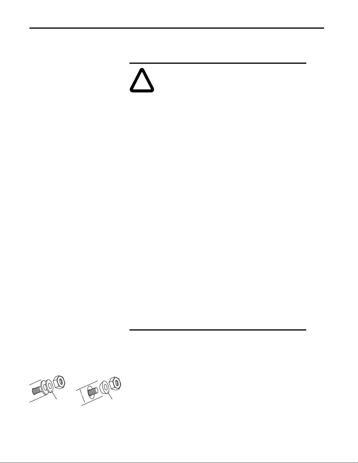
Special Instructions
Be lle v ille Wa s h e r (C uppe d
side toward mounting
surface)
Clamp W asher
ATTENT ION: When servicing any unit, do not drop
any nuts, bolts, washer s, etc. i nside the uni t, as th ey may
cause a short circuit on power up.
ATTENT ION: This drive system contains ESD
(Electrostatic Dis charge) sen sitive part s and assemblie s.
Static control precautions are required when installing,
testing, or repairing this assembly. Component damage
can result if ES D contr ol procedur es are not fol lowed. I f
you are not familiar with static control procedures, refer
to Allen-Bradley publication 8000-4.5.2, Guarding
Against Electrostatic Damage or any other applicable
ESD protection handbook.
Important:You will need to reuse parts that are removed from the unit.
Place parts, in the order removed, on a clean surface.
Important:Some washers, such as clamp a nd Belleville washer s, have only
one correct orientation.
Publication 2300-5.16 September 1999
Page 3

Power Fuse Replacement 3
!
Preliminary Steps
Replacing the Power Fuses
Before replacing the power fuses, shut off the power; lockout/tagout the
unit; and wait five minutes for the voltage to discharge. Open the bay door
to the power fuses.
1. Using a meter , test t he volt age acr oss the AC line , across t he DC bus , and
across each of the power fuses.
ATTENTION: If there is any voltage present, remove the
source of the voltage. Check for voltages again before
proceeding to the next step.
2. Remove the two bolts from the fuse and pull the fuse out.
3. Verify that the new fuse has the same rating as the old fuse (or check
your user manual for the appropriate fuse rating).
4. Secure the new fuse using the torques below:
Size of Bolt/Nut Torque
1/4 in (64mm)
5/16 in (79mm)
3/8 in (95mm)
1/2 in (127mm)
10 lb-ft
15 lb-ft
20 lb-ft
25 lb-ft
5. Repeat for each fuse to be replaced.
Figure 1
Replacing Power Fuses
AC Line Fuse for
K-code RGU shown
Publication 2300-5.16 September 1999
Page 4

Concluding Steps
After replacing the power fuses, check the unit for any tools or debris; then
close the bay door. Discard the damaged fuses according to your company
procedures and local ordinances.
Publication 2300-5.16 September 1999 PN 192893 (01)
Copyright 1999 of Rockwell International Corporation. Printed in the USA
 Loading...