

Page 1

User Manual
Micro820 Programmable Controllers
Catalog Numbers
LC20-20QBBR, 2080-LC20-20AWBR
2080-LC20-20QWB, 2080-LC20-20QBB, 2080-LC20-20AWB, 2080-LC20-20QWBR, 2080-
Page 2
Important User Information
IMPORTANT
Solid-state equipment has operational characteristics differing from those of electromechanical equipment. Safety
Guidelines for the Application, Installation and Maintenance of Solid State Controls (publication SGI-1.1
your local Rockwell Automation sales office or online at http://www.rockwellautomation.com/literature/
important differences between solid-state equipment and hard-wired electromechanical devices. Because of this difference,
and also because of the wide variety of uses for solid-state equipment, all persons responsible for applying this equipment
must satisfy themselves that each intended application of this equipment is acceptable.
In no event will Rockwell Automation, Inc. be responsible or liable for indirect or consequential damages resulting from
the use or application of this equipment.
The examples and diagrams in this manual are included solely for illustrative purposes. Because of the many variables and
requirements associated with any particular installation, Rockwell Automation, Inc. cannot assume responsibility or
liability for actual use based on the examples and diagrams.
No patent liability is assumed by Rockwell Automation, Inc. with respect to use of information, circuits, equipment, or
software described in this manual.
Reproduction of the contents of this manual, in whole or in part, without written permission of Rockwell Automation,
Inc., is prohibited.
Throughout this manual, when necessary, we use notes to make you aware of safety considerations.
WARNING: Identifies information about practices or circumstances that can cause an explosion in a hazardous
environment, which may lead to personal injury or death, property damage, or economic loss.
available from
) describes some
ATTENTION: Identifies information about practices or circumstances that can lead to personal injury or death,
property damage, or economic loss. Attentions help you identify a hazard, avoid a hazard, and recognize the
consequence
SHOCK HAZARD: Labels may be on or inside the equipment, for example, a drive or motor, to alert people that
dangerous voltage may be present.
BURN HAZARD: Labels may be on or inside the equipment, for example, a drive or motor, to alert people that
surfaces may reach dangerous temperatures.
Identifies information that is critical for successful application and understanding of the product.
Allen-Bradley, Rockwell Software, Rockwell Automation, Micro800, Micro820, Micro830, Micro850, Connected Components Workbench, and TechConnect are trademarks of Rockwell Automation, Inc.
Trademarks not belonging to Rockwell Automation are property of their respective companies.
Page 3

Preface
Read this preface to familiarize yourself with the rest of the manual. It provides
information concerning:
• who should use this manual
• the purpose of this manual
• related documentation
• supporting information for Micro800™
Who Should Use this Manual
Purpose of this Manual
Additional Resources
Use this manual if you are responsible for designing, installing, programming, or
troubleshooting control systems that use Micro800 controllers.
You should have a basic understanding of electrical circuitry and familiarity with
relay logic. If you do not, obtain the proper training before using this product.
This manual is a reference guide for Micro820 controllers. It describes the
procedures you use to install, wire, and troubleshoot your controller. This
manual:
• explains how to install and wire your controllers
• gives you an overview of the Micro800 controller system
Refer to the Online Help provided with Connected Components Workbench™
software for more information on programming your Micro800 controller.
These documents contain additional information concerning related Rockwell
Automation products.
Resource Description
Micro800 Plug-in Modules 2080-UM004 Information on features, configuration,
Micro800 Programmable Controller External AC
Power Supply Installation Instructions
2080-IN001
Micro820 Programmable Controllers Installation
Instructions, 2080-IN009
Micro800 Remote LCD Installation Instructions,
2080-IN010
Micro800 RS232/485 Isolated Serial Port Plug-in
Module Wiring Diagrams 2080-WD002
Micro800 Non-isolated Unipolar Analog Input
Plug-in Module Wiring Diagrams 2080-WD003
Micro800 Non-isolated Unipolar Analog Output
Plug-in Module Wiring Diagrams 2080-WD004
Micro800 Non-isolated RTD Plug-in Module
Wiring Diagrams 2080-WD005
installation, wiring, and specifications for the
Micro800 plug-in modules.
Information on mounting and wiring the optional
external power supply.
Information on installing, mounting, and wiring
the Micro820 controller.
Information on installing, mounting, and wiring
the Micro800 Remote LCD module.
Information on mounting and wiring the
Micro800 RS232/485 Isolated Serial Port Plug-in
Module.
Information on mounting and wiring the
Micro800 Non-isolated Unipolar Analog Input
Plug-in Module.
Information on mounting and wiring the
Micro800 Non-isolated Unipolar Analog Output
Plug-in Module.
Information on mounting and wiring the
Micro800 Non-isolated RTD Plug-in Module.
Rockwell Automation Publication 2080-UM005A-EN-E - December 2013 iii
Page 4

Preface
Resource Description
Micro800 Non-isolated Thermocouple Plug-in
Module Wiring Diagrams 2080-WD006
Micro800 Memory Backup and High Accuracy
RTC Plug-In Module Wiring Diagrams
2080-WD007
Micro800 6-Channel Trimpot Analog Input Plug-In
Module Wiring Diagrams 2080-WD008
Micro800 Digital Relay Output Plug-in Module
Wiring Diagrams 2080-WD010
Micro800 Digital Input, Output, and Combination
Plug-in Modules Wiring Diagrams 2080-WD011
Micro800 High Speed Counter Plug-in Module,
2080-WD012
Micro800 DeviceNet Plug-in Module,
2080-WD013
Industrial Automation Wiring and Grounding
Guidelines, publication 1770-4.1
Product Certifications website, http://
www.rockwellautomation.com/products/
certification/
Application Considerations for Solid-State
Controls SGI-1.1
National Electrical Code - Published by the
National Fire Protection Association of Boston,
MA.
Allen-Bradley Industrial Automation Glossary
AG-7.1
Information on mounting and wiring the
Micro800 Non-isolated Thermocouple Plug-in
Module.
Information on mounting and wiring the
Micro800 Memory Backup and High Accuracy
RTC Plug-In Module.
Information on mounting and wiring the
Micro800 6-Channel Trimpot Analog Input Plug-In
Module.
Information on mounting and wiring the
Micro800 Digital Relay Output Plug-in Module.
Information on mounting and wiring the
Micro800 Digital Input, Output, and Combination
Plug-in Modules.
Information on mounting and wiring the High
Speed Counter Plug-in module.
Information on mounting and wiring the
Micro800 DeviceNet plug-in module.
Provides general guidelines for installing a
Rockwell Automation industrial system.
Provides declarations of conformity, certificates,
and other certification details.
A description of important differences between
solid-state programmable controller products
and hard-wired electromechanical devices.
An article on wire sizes and types for grounding
electrical equipment.
A glossary of industrial automation terms and
abbreviations.
You can view or download publications at http://www.rockwellautomation.com/
literature/. To order paper copies of technical documentation, contact your local
Rockwell Automation distributor or sales representative.
You can download the latest version of Connected Components Workbench for
your Micro800 at the URL below.
http://ab.rockwellautomation.com/Programmable-Controllers/ConnectedComponents-Workbench-Software.
iv Rockwell Automation Publication 2080-UM005A-EN-E - December 2013
Page 5

Table of Contents
Preface
Hardware Overview
About Your Controller
Who Should Use this Manual . . . . . . . . . . . . . . . . . . . . . . . . . . . . . . . . . . . . . . . 7
Purpose of this Manual . . . . . . . . . . . . . . . . . . . . . . . . . . . . . . . . . . . . . . . . . . . . . 7
Additional Resources . . . . . . . . . . . . . . . . . . . . . . . . . . . . . . . . . . . . . . . . . . . . . . . 7
Chapter 1
Hardware Features . . . . . . . . . . . . . . . . . . . . . . . . . . . . . . . . . . . . . . . . . . . . . . . . . 1
Inputs and Outputs. . . . . . . . . . . . . . . . . . . . . . . . . . . . . . . . . . . . . . . . . . . . . 3
Embedded microSD (Micro Secure Digital) Card Slot . . . . . . . . . . . . . 3
Embedded RS232/RS485 Serial Port Combo . . . . . . . . . . . . . . . . . . . . . 3
Embedded Ethernet Support . . . . . . . . . . . . . . . . . . . . . . . . . . . . . . . . . . . . 4
Chapter 2
Programming Software for Micro800 Controllers. . . . . . . . . . . . . . . . . . . . . 7
Obtain Connected Components Workbench. . . . . . . . . . . . . . . . . . . . . 7
Use Connected Components Workbench . . . . . . . . . . . . . . . . . . . . . . . . 7
Agency Certifications. . . . . . . . . . . . . . . . . . . . . . . . . . . . . . . . . . . . . . . . . . . . . . . 7
Compliance to European Union Directives. . . . . . . . . . . . . . . . . . . . . . . . . . . 7
EMC Directive. . . . . . . . . . . . . . . . . . . . . . . . . . . . . . . . . . . . . . . . . . . . . . . . . 8
Low Voltage Directive . . . . . . . . . . . . . . . . . . . . . . . . . . . . . . . . . . . . . . . . . . 8
Installation Considerations . . . . . . . . . . . . . . . . . . . . . . . . . . . . . . . . . . . . . . . . . 8
Environment and Enclosure . . . . . . . . . . . . . . . . . . . . . . . . . . . . . . . . . . . 10
Preventing Electrostatic Discharge . . . . . . . . . . . . . . . . . . . . . . . . . . . . . 10
Safety Considerations . . . . . . . . . . . . . . . . . . . . . . . . . . . . . . . . . . . . . . . . . . . . 10
North American Hazardous Location Approval. . . . . . . . . . . . . . . . . 11
Disconnecting Main Power. . . . . . . . . . . . . . . . . . . . . . . . . . . . . . . . . . . . 11
Safety Circuits . . . . . . . . . . . . . . . . . . . . . . . . . . . . . . . . . . . . . . . . . . . . . . . 12
Power Distribution . . . . . . . . . . . . . . . . . . . . . . . . . . . . . . . . . . . . . . . . . . 12
Periodic Tests of Master Control Relay Circuit . . . . . . . . . . . . . . . . . 12
Power Considerations . . . . . . . . . . . . . . . . . . . . . . . . . . . . . . . . . . . . . . . . . . . . 12
Isolation Transformers. . . . . . . . . . . . . . . . . . . . . . . . . . . . . . . . . . . . . . . . 13
Power Supply Inrush. . . . . . . . . . . . . . . . . . . . . . . . . . . . . . . . . . . . . . . . . . 13
Loss of Power Source . . . . . . . . . . . . . . . . . . . . . . . . . . . . . . . . . . . . . . . . . 13
Input States on Power Down . . . . . . . . . . . . . . . . . . . . . . . . . . . . . . . . . . 14
Other Types of Line Conditions. . . . . . . . . . . . . . . . . . . . . . . . . . . . . . . 14
Preventing Excessive Heat . . . . . . . . . . . . . . . . . . . . . . . . . . . . . . . . . . . . . . . . 14
Master Control Relay. . . . . . . . . . . . . . . . . . . . . . . . . . . . . . . . . . . . . . . . . . . . . 14
Using Emergency-Stop Switches . . . . . . . . . . . . . . . . . . . . . . . . . . . . . . . 15
Schematic (Using IEC Symbols) . . . . . . . . . . . . . . . . . . . . . . . . . . . . . . . 17
Schematic (Using ANSI/CSA Symbols). . . . . . . . . . . . . . . . . . . . . . . . 18
Chapter 3
Install Your Controller
Rockwell Automation Publication 2080-UM005A-EN-E - December 2013 v
Controller Mounting Dimensions . . . . . . . . . . . . . . . . . . . . . . . . . . . . . . . . . 19
Module Spacing . . . . . . . . . . . . . . . . . . . . . . . . . . . . . . . . . . . . . . . . . . . . . . 20
DIN Rail Mounting . . . . . . . . . . . . . . . . . . . . . . . . . . . . . . . . . . . . . . . . . . 20
Panel Mounting . . . . . . . . . . . . . . . . . . . . . . . . . . . . . . . . . . . . . . . . . . . . . . 20
Panel Mounting Dimensions . . . . . . . . . . . . . . . . . . . . . . . . . . . . . . . . . . 21
Page 6

Table of Contents
Wire Your Controller
Connect the Controller to an EtherNet/IP Network . . . . . . . . . . . . . . . . 21
Install the microSD Card . . . . . . . . . . . . . . . . . . . . . . . . . . . . . . . . . . . . . . . . . 22
Install the 2080-REMLCD Module. . . . . . . . . . . . . . . . . . . . . . . . . . . . . . . . 23
Chapter 4
Wiring Requirements and Recommendation . . . . . . . . . . . . . . . . . . . . . . . 25
Wire Requirements . . . . . . . . . . . . . . . . . . . . . . . . . . . . . . . . . . . . . . . . . . . 26
Use Surge Suppressors . . . . . . . . . . . . . . . . . . . . . . . . . . . . . . . . . . . . . . . . . . . . 26
Recommended Surge Suppressors . . . . . . . . . . . . . . . . . . . . . . . . . . . . . . 28
Grounding the Controller. . . . . . . . . . . . . . . . . . . . . . . . . . . . . . . . . . . . . . . . . 29
Wiring Diagrams . . . . . . . . . . . . . . . . . . . . . . . . . . . . . . . . . . . . . . . . . . . . . . . . . 29
Controller I/O Wiring. . . . . . . . . . . . . . . . . . . . . . . . . . . . . . . . . . . . . . . . . . . . 30
Minimize Electrical Noise . . . . . . . . . . . . . . . . . . . . . . . . . . . . . . . . . . . . . 31
Analog Channel Wiring Guidelines . . . . . . . . . . . . . . . . . . . . . . . . . . . . 31
Minimize Electrical Noise on Analog Channels . . . . . . . . . . . . . . . . . 31
Grounding Your Analog Cable . . . . . . . . . . . . . . . . . . . . . . . . . . . . . . . . 32
Wiring Examples . . . . . . . . . . . . . . . . . . . . . . . . . . . . . . . . . . . . . . . . . . . . . 32
Wiring Analog Channels. . . . . . . . . . . . . . . . . . . . . . . . . . . . . . . . . . . . . . . . . . 33
Communication Connections
Chapter 5
Overview . . . . . . . . . . . . . . . . . . . . . . . . . . . . . . . . . . . . . . . . . . . . . . . . . . . . . . . . 37
Supported Communication Protocols. . . . . . . . . . . . . . . . . . . . . . . . . . . . . . 37
Modbus RTU . . . . . . . . . . . . . . . . . . . . . . . . . . . . . . . . . . . . . . . . . . . . . . . . 37
Modbus/TCP Client/Server. . . . . . . . . . . . . . . . . . . . . . . . . . . . . . . . . . . 38
CIP Symbolic Client/Server . . . . . . . . . . . . . . . . . . . . . . . . . . . . . . . . . . . 38
CIP Client Messaging . . . . . . . . . . . . . . . . . . . . . . . . . . . . . . . . . . . . . . . . . 39
ASCII . . . . . . . . . . . . . . . . . . . . . . . . . . . . . . . . . . . . . . . . . . . . . . . . . . . . . . . 40
CIP Communications Pass-thru . . . . . . . . . . . . . . . . . . . . . . . . . . . . . . . . . . . 40
Examples of Supported Architectures. . . . . . . . . . . . . . . . . . . . . . . . . . . 40
Use Modems with Micro800 Controllers. . . . . . . . . . . . . . . . . . . . . . . . . . . 41
Making a DF1 Point-to-Point Connection. . . . . . . . . . . . . . . . . . . . . . 41
Construct Your Own Modem Cable . . . . . . . . . . . . . . . . . . . . . . . . . . . 41
Configure Serial Port . . . . . . . . . . . . . . . . . . . . . . . . . . . . . . . . . . . . . . . . . . . . . 42
Configure CIP Serial Driver . . . . . . . . . . . . . . . . . . . . . . . . . . . . . . . . . . . 43
Configure Modbus RTU . . . . . . . . . . . . . . . . . . . . . . . . . . . . . . . . . . . . . . 45
Configure ASCII . . . . . . . . . . . . . . . . . . . . . . . . . . . . . . . . . . . . . . . . . . . . . 47
Configure Ethernet Settings. . . . . . . . . . . . . . . . . . . . . . . . . . . . . . . . . . . . . . . 48
Ethernet Host Name. . . . . . . . . . . . . . . . . . . . . . . . . . . . . . . . . . . . . . . . . . 49
Chapter 6
Program Execution in Micro800
vi Rockwell Automation Publication 2080-UM005A-EN-E - December 2013
Overview of Program Execution . . . . . . . . . . . . . . . . . . . . . . . . . . . . . . . . . . . 51
Execution Rules . . . . . . . . . . . . . . . . . . . . . . . . . . . . . . . . . . . . . . . . . . . . . . 52
Controller Load and Performance Considerations . . . . . . . . . . . . . . . . . . 52
Periodic Execution of Programs . . . . . . . . . . . . . . . . . . . . . . . . . . . . . . . . 53
Page 7

Controller Security
Chapter 1
Power Up and First Scan. . . . . . . . . . . . . . . . . . . . . . . . . . . . . . . . . . . . . . . . . . 53
Variable Retention . . . . . . . . . . . . . . . . . . . . . . . . . . . . . . . . . . . . . . . . . . . 54
Memory Allocation . . . . . . . . . . . . . . . . . . . . . . . . . . . . . . . . . . . . . . . . . . . . . . 54
Guidelines and Limitations for Advanced Users . . . . . . . . . . . . . . . . . . . . 54
Chapter 7
Exclusive Access. . . . . . . . . . . . . . . . . . . . . . . . . . . . . . . . . . . . . . . . . . . . . . . . . . 57
Password Protection. . . . . . . . . . . . . . . . . . . . . . . . . . . . . . . . . . . . . . . . . . . . . . 57
Compatibility. . . . . . . . . . . . . . . . . . . . . . . . . . . . . . . . . . . . . . . . . . . . . . . . . . . . 57
Work with a Locked Controller . . . . . . . . . . . . . . . . . . . . . . . . . . . . . . . . . . . 58
Upload from a Password-Protected Controller. . . . . . . . . . . . . . . . . . 58
Debug a Password-Protected Controller. . . . . . . . . . . . . . . . . . . . . . . . 59
Download to a Password-Protected Controller. . . . . . . . . . . . . . . . . . 59
Transfer Controller Program and Lock Receiving Controller. . . . . 59
Back Up a Password-Protected Controller . . . . . . . . . . . . . . . . . . . . . . 60
Configure Controller Password . . . . . . . . . . . . . . . . . . . . . . . . . . . . . . . . . . . 60
Recover from a Lost Password . . . . . . . . . . . . . . . . . . . . . . . . . . . . . . . . . . . . . 61
Using the Micro800 Remote LCD
Using microSD Cards
Chapter 8
Overview . . . . . . . . . . . . . . . . . . . . . . . . . . . . . . . . . . . . . . . . . . . . . . . . . . . . . . . . 63
USB Mode . . . . . . . . . . . . . . . . . . . . . . . . . . . . . . . . . . . . . . . . . . . . . . . . . . . . . . 64
Text Display Mode . . . . . . . . . . . . . . . . . . . . . . . . . . . . . . . . . . . . . . . . . . . . . . . 65
Startup Screen . . . . . . . . . . . . . . . . . . . . . . . . . . . . . . . . . . . . . . . . . . . . . . . 65
Navigate the Remote LCD . . . . . . . . . . . . . . . . . . . . . . . . . . . . . . . . . . . . 66
Main Menu . . . . . . . . . . . . . . . . . . . . . . . . . . . . . . . . . . . . . . . . . . . . . . . . . . 66
User-defined Screens. . . . . . . . . . . . . . . . . . . . . . . . . . . . . . . . . . . . . . . . . . 69
Backup and Restore . . . . . . . . . . . . . . . . . . . . . . . . . . . . . . . . . . . . . . . . . . . . . . 71
Hardware Features, Installation, and Specifications. . . . . . . . . . . . . . . . . 71
Chapter 9
Overview . . . . . . . . . . . . . . . . . . . . . . . . . . . . . . . . . . . . . . . . . . . . . . . . . . . . . . . . 73
Project Backup and Restore . . . . . . . . . . . . . . . . . . . . . . . . . . . . . . . . . . . . . . . 73
Backup and Restore Directory Structure. . . . . . . . . . . . . . . . . . . . . . . . 75
Powerup Settings in ConfigMeFirst.txt. . . . . . . . . . . . . . . . . . . . . . . . . 76
General Configuration Rules in ConfigMeFirst.txt . . . . . . . . . . . . . . 77
ConfigMeFirst.txt Errors. . . . . . . . . . . . . . . . . . . . . . . . . . . . . . . . . . . . . . 77
Datalog. . . . . . . . . . . . . . . . . . . . . . . . . . . . . . . . . . . . . . . . . . . . . . . . . . . . . . . . . . 78
Datalog Directory Structure . . . . . . . . . . . . . . . . . . . . . . . . . . . . . . . . . . 79
Datalog Function (DLG) Block . . . . . . . . . . . . . . . . . . . . . . . . . . . . . . . 80
Recipe. . . . . . . . . . . . . . . . . . . . . . . . . . . . . . . . . . . . . . . . . . . . . . . . . . . . . . . . . . . 83
Recipe Directory Structure . . . . . . . . . . . . . . . . . . . . . . . . . . . . . . . . . . . 84
Recipe Function (RCP) Block . . . . . . . . . . . . . . . . . . . . . . . . . . . . . . . . . 84
Quickstart Projects for Datalog and Recipe Function Blocks . . . . . . . . . 87
Use the Datalog Feature . . . . . . . . . . . . . . . . . . . . . . . . . . . . . . . . . . . . . . 88
Rockwell Automation Publication 2080-UM005A-EN-E - December 2013 vii
Page 8

Table of Contents
Specifications
Use the Recipe Feature . . . . . . . . . . . . . . . . . . . . . . . . . . . . . . . . . . . . . . . . 94
Appendix A
. . . . . . . . . . . . . . . . . . . . . . . . . . . . . . . . . . . . . . . . . . . . . . . . . . . . . . . . . . . . . . . . 101
Appendix B
Troubleshooting
Quickstarts
IPID Function Block
Status Indicators on the Controller . . . . . . . . . . . . . . . . . . . . . . . . . . . . . . . 111
Normal Operation. . . . . . . . . . . . . . . . . . . . . . . . . . . . . . . . . . . . . . . . . . . 112
Error Conditions . . . . . . . . . . . . . . . . . . . . . . . . . . . . . . . . . . . . . . . . . . . . . . . . 112
Error codes . . . . . . . . . . . . . . . . . . . . . . . . . . . . . . . . . . . . . . . . . . . . . . . . . . . . . 113
Controller Error Recovery Model. . . . . . . . . . . . . . . . . . . . . . . . . . . . . . . . . 119
Calling Rockwell Automation for Assistance. . . . . . . . . . . . . . . . . . . . . . . 120
Appendix C
Flash Upgrade Your Micro800 Firmware . . . . . . . . . . . . . . . . . . . . . . . . . . 121
Establish Communications between RSLinx and a Micro820 Controller
through USB Port on 2080-REMLCD. . . . . . . . . . . . . . . . . . . . . . . . . . . . 124
Configure Controller Password. . . . . . . . . . . . . . . . . . . . . . . . . . . . . . . . . . . 128
Set Controller Password. . . . . . . . . . . . . . . . . . . . . . . . . . . . . . . . . . . . . . 129
Change Password . . . . . . . . . . . . . . . . . . . . . . . . . . . . . . . . . . . . . . . . . . . . 130
Clear Password . . . . . . . . . . . . . . . . . . . . . . . . . . . . . . . . . . . . . . . . . . . . . . 131
Forcing I/Os . . . . . . . . . . . . . . . . . . . . . . . . . . . . . . . . . . . . . . . . . . . . . . . . . . . . 132
Checking if Forces (locks) are Enabled. . . . . . . . . . . . . . . . . . . . . . . . . 132
I/O Forces After a Power Cycle . . . . . . . . . . . . . . . . . . . . . . . . . . . . . . . 133
Appendix D
How to Autotune . . . . . . . . . . . . . . . . . . . . . . . . . . . . . . . . . . . . . . . . . . . . . . . 137
How Autotune Works . . . . . . . . . . . . . . . . . . . . . . . . . . . . . . . . . . . . . . . 138
Troubleshooting an Autotune Process. . . . . . . . . . . . . . . . . . . . . . . . . . . . . 139
PID Application Example . . . . . . . . . . . . . . . . . . . . . . . . . . . . . . . . . . . . . . . . 140
PID Code Sample . . . . . . . . . . . . . . . . . . . . . . . . . . . . . . . . . . . . . . . . . . . 141
Appendix F
Modbus Mapping for Micro800
Modbus Mapping . . . . . . . . . . . . . . . . . . . . . . . . . . . . . . . . . . . . . . . . . . . . . . . 143
Endian Configuration. . . . . . . . . . . . . . . . . . . . . . . . . . . . . . . . . . . . . . . . 143
Mapping Address Space and supported Data Types . . . . . . . . . . . . . 143
Example 1, PanelView Component HMI (Master) to Micro800
(Slave) . . . . . . . . . . . . . . . . . . . . . . . . . . . . . . . . . . . . . . . . . . . . . . . . . . . . . . 144
Example 2, Micro800 (Master) to PowerFlex 4M Drive (Slave) . . 145
Performance. . . . . . . . . . . . . . . . . . . . . . . . . . . . . . . . . . . . . . . . . . . . . . . . . 148
Index
viii Rockwell Automation Publication 2080-UM005A-EN-E - December 2013
Page 9
Hardware Overview
IMPORTANT
Chapter
1
Hardware Features
This chapter provides an overview of the Micro820 hardware features. It has the
following topics:
Topic Page
Hardware Features 1
Embedded microSD (Micro Secure Digital) Card Slot 3
Embedded RS232/RS485 Serial Port Combo 3
Embedded Ethernet Support 4
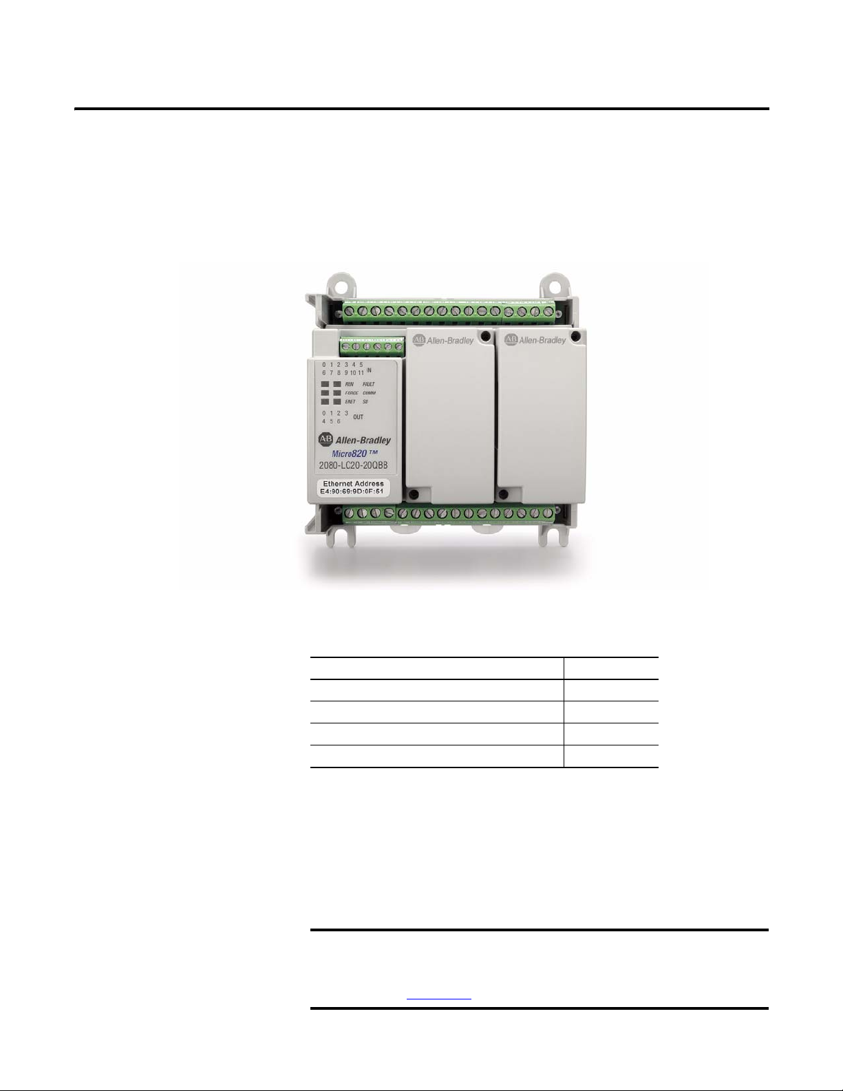
Micro820 controllers are 20-point economical brick style controllers with
embedded inputs and outputs. These controllers can accommodate up to two
plug-in modules and can connect to a remote LCD (2080-REMLCD) for
configuring. The Micro820 controller also has a microSD™ card slot for project
backup and restore, and datalog and recipe.
The Micro820 controller supports all Micro800 plug-in modules, except
for the 2080-MEMBAK-RTC.
For more information, see Micro800 Plug-in Modules User, publication
2080-UM004
.
Rockwell Automation Publication 2080-UM005A-EN-E - December 2013 1
Page 10
Chapter 1 Hardware Overview
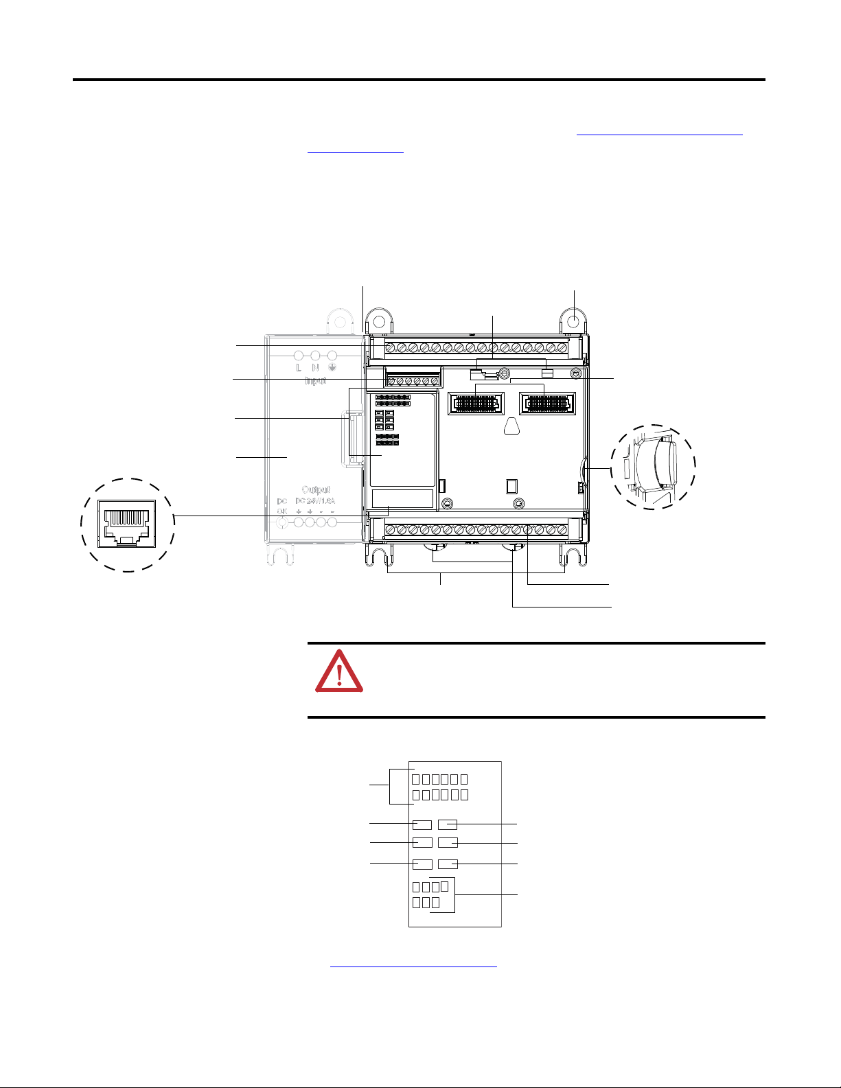
46206
Status indicators
RS232/RS485 non-isolated
combo serial ports
Removable/fixed terminal blocks
Power supply
RJ-45 Ethernet
connector port
microSD (Micro
Secure Digital)
card slot
40-pin high-speed plug-in
connector slot
Removable/fixed terminal blocks
Plug-in latch
Mounting screw hole
Optional power supply slot
Mounting feet
DIN rail mounting latch
Input status
Run status
Fault status
Force status
Comm status
ENET status
SD status
Output status
46207
For information on the REMLCD module, see Using the Micro800 Remote
LCD on page 63.
The controller also accommodates any class 2 rated 24V DC output power
supply that meets minimum specifications such as the optional Micro800 power
supply.
Micro820 Controllers
2 Rockwell Automation Publication 2080-UM005A-EN-E - December 2013
ATTENTION: Removable terminal blocks are available on catalog
numbers that end in R (for example, 2080-LC20-20QBBR). Fixed terminal
blocks are available on catalog numbers that do not end in R (for example,
2080-LC20-20QBB).
Status Indicators
See Troubleshooting on page 111 for descriptions of status indicator operation.
Page 11

Hardware Overview Chapter 1
IMPORTANT
Inputs and Outputs
Number and Types of Inputs/Outputs for Micro820 Controllers
Controller
Family
Micro820 2080-LC20-20QBB – – 12 7 – 1 4 1
Catalogs Inputs Outputs Analog Out
120V AC 120 /
240V AC
2080-LC20-20QWB – – 12 7 – – 1 4 –
2080-LC20-20AWB 8 – 4 7 – – 1 4 –
2080-LC20-20QBBR – – 12 – 7 – 1 4 1
2080-LC20-20QWBR – – 12 7 – – 1 4 –
2080-LC20-20AWBR 8 – 4 7 – 1 4 –
24V DC Relay 24V DC
Source
24V DC
Sink
0…10V DC
Analog In
0…10V (shared
with DC In)
Embedded microSD (Micro Secure Digital) Card Slot
Micro820 controllers support microSD cards through an embedded microSD
card slot. It supports Class 6 and 10 SDSC and SDHC microSD cards, with
FAT32/16 formats, 32 GB maximum size. Industrial grade cards such as Swissbit
S-200u/S300u are recommended. The microSD file system supports only one file
partition. Class 4 cards are not supported.
PWM
Support
The microSD card is primarily used for project backup and restore, as well as
datalog and recipe functions. It can also be used to configure powerup settings
(such as controller mode, IP address, and so on) through an optional
ConfigMeFirst.txt file.
For more information, see Using microSD Cards
To help you troubleshoot microSD card-related errors, see Troubleshooting
on page 73.
on
page 111.
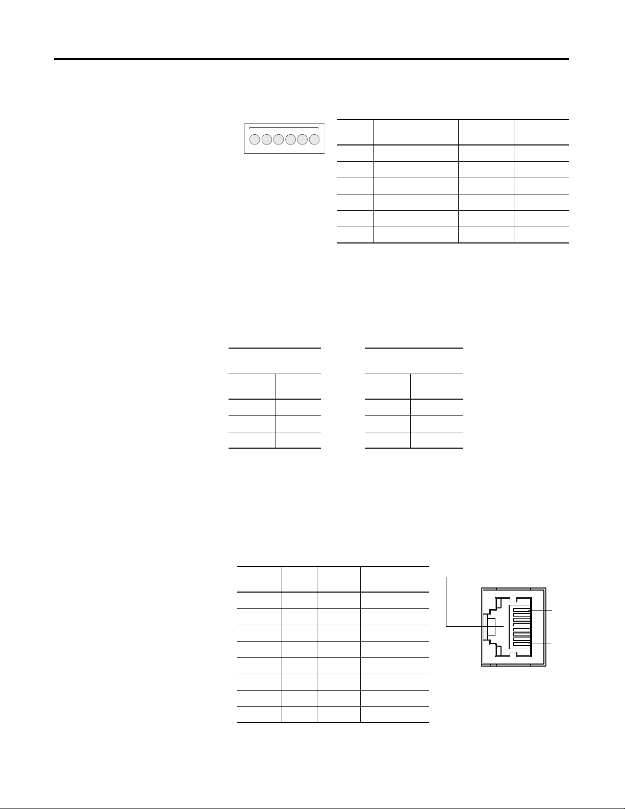
Embedded RS232/RS485 Serial Port Combo
The Micro820 controller supports an embedded non-isolated RS232/RS485
combo communications port. Only one port (RS232 or RS485) can work at any
given time. The baud rate of this port supports up to 38.4 K.
The communication port uses a 6-pin 3.5 mm terminal block with pin definition
shown in the following table.
Serial port cables should not exceed 3 m length.
Rockwell Automation Publication 2080-UM005A-EN-E - December 2013 3
Page 12
Chapter 1 Hardware Overview
D-
D+ G
Rx
Tx
12345
6
G
RJ-45 connector
RJ-45 Ethernet Port Pin Mapping
Contact
Number
Signal Direction Primary
Function
1 TX+ OUT Transmit data +
2 TX- OUT Transmit data -
3 RX+ IN Receive data +
4–––
5–––
6 RX- IN Receive data -
7–––
8–––
46210
1
8
RS232/RS485 Serial Port Pin Definition
Pin Definition RS485
Example
RS232
Example
1 RS485+ RS485+ (not used)
2 RS485- RS485- (not used)
3 GND GND GND
4 RS232 input (receiver) (not used) RxD
5 RS232 output (driver) (not used) TxD
6 GND GND GND
The communication port (both RS232 and RS485) are non-isolated. The signal
ground of the port is not isolated to the logic ground of the controller.
The RS232 port supports connection to the Micro800 Remote LCD module
number
Micro820 Serial Port
Terminal Block
Pin
Signal
number
(2080-REMLCD).
REMLCD to Micro820 Serial Port Terminal Block Wiring
REMLCD Serial Port
Terminal Block
Signal Pin
RS232 TX 1 <--------> 4 RX RS232
RS232 RX 2 <--------> 5 TX RS232
RS232 G 3 <--------> 6 G RS232
4 Rockwell Automation Publication 2080-UM005A-EN-E - December 2013
Embedded Ethernet Support
A 10/100 Base-T Port is available for connection to an Ethernet network through
any standard RJ-45 Ethernet cable.
Page 13
Hardware Overview Chapter 1
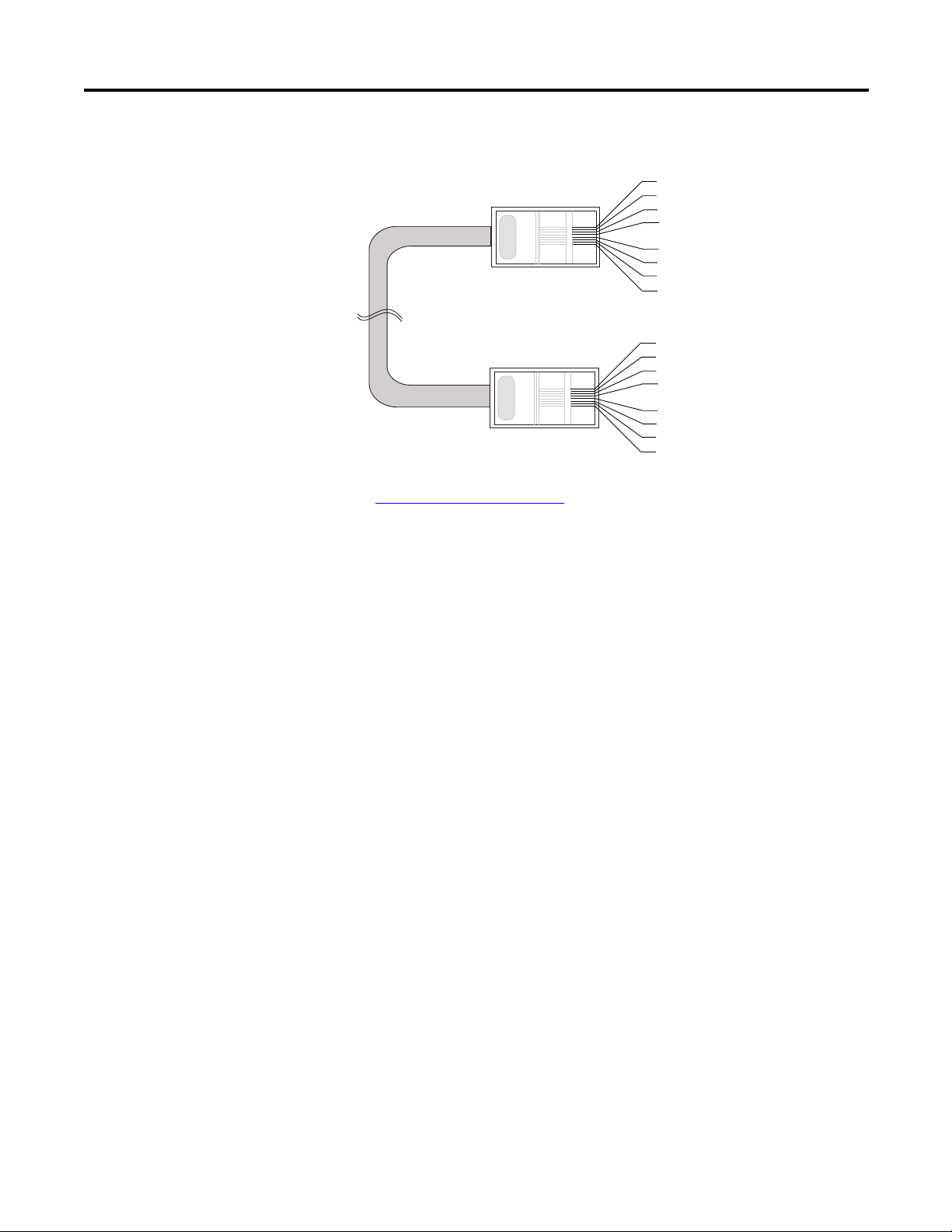
1
2
3
4
5
6
7
8
1
2
3
4
5
6
7
8
white-orange
orange
white-green
blue
white-blue
green
white-brown
brown
white-orange
orange
white-green
blue
white-blue
green
white-brown
brown
46223
Ethernet port pin-to-pin connection
See Troubleshooting on page 111 for descriptions of ENET status indicator.
Rockwell Automation Publication 2080-UM005A-EN-E - December 2013 5
Page 14

Chapter 1 Hardware Overview
Notes:
6 Rockwell Automation Publication 2080-UM005A-EN-E - December 2013
Page 15

About Your Controller
Chapter
2
Programming Software for Micro800 Controllers
Connected Components Workbench is a set of collaborative tools supporting
Micro800 controllers. It is based on Rockwell Automation and Microsoft Visual
Studio technology and offers controller programming, device configuration and
integration with HMI editor. Use this software to program your controllers,
configure your devices and design your operator interface applications.
Connected Components Workbench provides a choice of IEC 61131-3
programming languages (ladder diagram, function block diagram, structured
text) with user defined function block support that optimizes machine control.
Obtain Connected Components Workbench
A free download is available at:
http://ab.rockwellautomation.com/Programmable-Controllers/ConnectedComponents-Workbench-Software
Use Connected Components Workbench
To help you program your controller through the Connected Components
Workbench software, you can refer to the Connected Components Workbench
Online Help (it comes with the software).
Agency Certifications
Compliance to European Union Directives
Rockwell Automation Publication 2080-UM005A-EN-E - December 2013 7
• UL Listed Industrial Control Equipment, certified for US and Canada.
UL Listed for Class I, Division 2 Group A,B,C,D Hazardous Locations,
certified for U.S. and Canada.
• CE marked for all applicable directives
• C-Tick marked for all applicable acts
• KC - Korean Registration of Broadcasting and Communications
Equipment, compliant with: Article 58-2 of Radio Waves Act, Clause 3.
This product has the CE mark and is approved for installation within the
European Union and EEA regions. It has been designed and tested to meet the
following directives.
Page 16

Chapter 2 About Your Controller
EMC Directive
This product is tested to meet Council Directive 2004/108/EC Electromagnetic
Compatibility (EMC) and the following standards, in whole or in part,
documented in a technical construction file:
• EN 61131-2; Programmable Controllers (Clause 8, Zone A & B)
• EN 61131-2; Programmable Controllers (Clause 11)
• EN 61000-6-4
EMC - Part 6-4: Generic Standards - Emission Standard for Industrial
Environments
• EN 61000-6-2
EMC - Part 6-2: Generic Standards - Immunity for Industrial
Environments
This product is intended for use in an industrial environment.
Installation Considerations
Low Voltage Directive
This product is tested to meet Council Directive 2006/95/ECLow Voltage, by
applying the safety requirements of EN 61131-2 Programmable Controllers, Part
2 - Equipment Requirements and Tests.
For specific information required by EN 61131-2, see the appropriate sections in
this publication, as well as the following Allen-Bradley publications:
• Industrial Automation Wiring and Grounding Guidelines for Noise
Immunity, publication 1770-4.1
• Guidelines for Handling Lithium Batteries, publication AG-5.4
• Automation Systems Catalog, publication B115
Most applications require installation in an industrial enclosure (Pollution
(1)
Degree 2
Category II
) to reduce the effects of electrical interference (Over Voltage
(2)
) and environmental exposure.
Locate your controller as far as possible from power lines, load lines, and other
sources of electrical noise such as hard-contact switches, relays, and AC motor
drives. For more information on proper grounding guidelines, see the Industrial
Automation Wiring and Grounding Guidelines publication 1770-4.1
.
.
(1) Pollution Degree 2 is an environment where normally only non-conductive pollution occurs except that
occassionally temporary conductivity caused by condensation shall be expected.
(2) Overvoltage Category II is the load level section of the electrical distribution system. At this level, transient
voltages are controlled and do not exceed the impulse voltage capability of the products insulation.
8 Rockwell Automation Publication 2080-UM005A-EN-E - December 2013
Page 17
About Your Controller Chapter 2
WARNING: When used in a Class I, Division 2, hazardous location, this equipment must be mounted in a
suitable enclosure with proper wiring method that complies with the governing electrical codes.
WARNING: If you connect or disconnect the serial cable with power applied to this module or the serial
device on the other end of the cable, an electrical arc can occur. This could cause an explosion in hazardous
location installations. Be sure that power is removed or the area is nonhazardous before proceeding.
WARNING: The local programming terminal port is intended for temporary use only and must not be
connected or disconnected unless the area is assured to be nonhazardous.
WARNING: Exposure to some chemicals may degrade the sealing properties of materials used in the
Relays. It is recommended that the User periodically inspect these devices for any degradation of
properties and replace the module if degradation is found.
WARNING: If you insert or remove the plug-in module while backplane power is on, an electrical arc can
occur. This could cause an explosion in hazardous location installations. Be sure that power is removed or
the area is nonhazardous before proceeding.
WARNING: When you connect or disconnect the Removable Terminal Block (RTB) with field side power
applied, an electrical arc can occur. This could cause an explosion in hazardous location installations.
WARNING: Be sure that power is removed or the area is nonhazardous before proceeding.
ATTENTION: To comply with the CE Low Voltage Directive (LVD), this equipment must be powered from a
source compliant with the following: Safety Extra Low Voltage (SELV) or Protected Extra Low Voltage (PELV).
ATTENTION: To comply with UL restrictions, this equipment must be powered from a Class 2 source.
ATTENTION: Be careful when stripping wires. Wire fragments that fall into the controller could cause
damage. Once wiring is complete, make sure the controller is free of all metal fragments.
ATTENTION: Electrostatic discharge can damage semiconductor devices inside the module. Do not touch
the connector pins or other sensitive areas.
ATTENTION: The serial cables are not to exceed 3.0 m (9.84 ft).
ATTENTION: Do not wire more than 2 conductors on any single terminal.
ATTENTION: Do not remove the Removable Terminal Block (RTB) until power is removed.
Rockwell Automation Publication 2080-UM005A-EN-E - December 2013 9
Page 18

Chapter 2 About Your Controller
Environment and Enclosure
This equipment is intended for use in a Pollution Degree 2 industrial
environment, in overvoltage Category II applications (as defined in IEC
60664-1), at altitudes up to 2000 m (6562 ft) without derating.
This equipment is considered Group 1, Class A industrial equipment
according to IEC/CISPR 11. Without appropriate precautions, there may be
difficulties with electromagnetic compatibility in residential and other
environments due to conducted and radiated disturbances.
This equipment is supplied as open-type equipment. It must be mounted
within an enclosure that is suitably designed for those specific
environmental conditions that will be present and appropriately designed
to prevent personal injury resulting from accessibility to live parts. The
enclosure must have suitable flame-retardant properties to prevent or
minimize the spread of flame, complying with a flame spread rating of
5VA, V2, V1, V0 (or equivalent) if non-metallic. The interior of the enclosure
must be accessible only by the use of a tool. Subsequent sections of this
publication may contain additional information regarding specific
enclosure type ratings that are required to comply with certain product
safety certifications.
In addition to this publication, see:
• Industrial Automation Wiring and Grounding Guidelines, Rockwell
Automation publication 1770-4.1
• NEMA Standard 250 and IEC 60529, as applicable, for explanations of the
degrees of protection provided by different types of enclosure.
, for additional installation requirements.
Preventing Electrostatic Discharge
This equipment is sensitive to electrostatic discharge, which can cause
internal damage and affect normal operation. Follow these guidelines
when you handle this equipment:
• Touch a grounded object to discharge potential static.
• Wear an approved grounding wriststrap.
• Do not touch connectors or pins on component boards.
• Do not touch circuit components inside the equipment.
• Use a static-safe workstation, if available.
• Store the equipment in appropriate static-safe packaging when not in use.
Safety Considerations
Safety considerations are an important element of proper system installation.
Actively thinking about the safety of yourself and others, as well as the condition
10 Rockwell Automation Publication 2080-UM005A-EN-E - December 2013
Page 19

About Your Controller Chapter 2
of your equipment, is of primary importance. We recommend reviewing the
following safety considerations.
North American Hazardous Location Approval
The following information applies when operating this equipment
in hazardous locations:
Products marked "CL I, DIV 2, GP A, B, C, D" are suitable for use in Class I
Division 2 Groups A, B, C, D, Hazardous Locations and nonhazardous
locations only. Each product is supplied with markings on the rating
nameplate indicating the hazardous location temperature code. When
combining products within a system, the most adverse temperature code
(lowest "T" number) may be used to help determine the overall
temperature code of the system. Combinations of equipment in your
system are subject to investigation by the local Authority Having
Jurisdiction at the time of installation.
EXPLOSION HAZARD
• Do not disconnect equipment unless power has been
removed or the area is known to be nonhazardous.
• Do not disconnect connections to this equipment unless
power has been removed or the area is known to be
nonhazardous. Secure any external connections that mate to
this equipment by using screws, sliding latches, threaded
connectors, or other means provided with this product.
• Substitution of any component may impair suitability for
Class I, Division 2.
• If this product contains batteries, they must only be changed
in an area known to be nonhazardous.
Informations sur l’utilisation de cet équipement en environnements
dangereux:
Les produits marqués "CL I, DIV 2, GP A, B, C, D" ne conviennent qu'à une
utilisation en environnements de Classe I Division 2 Groupes A, B, C, D
dangereux et non dangereux. Chaque produit est livré avec des marquages
sur sa plaque d'identification qui indiquent le code de température pour les
environnements dangereux. Lorsque plusieurs produits sont combinés dans
un système, le code de température le plus défavorable (code de
température le plus faible) peut être utilisé pour déterminer le code de
température global du système. Les combinaisons d'équipements dans le
système sont sujettes à inspection par les autorités locales qualifiées au
moment de l'installation.
RISQUE D’EXPLOSION
• Couper le courant ou s'assurer que l'environnement est classé
non dangereux avant de débrancher l'équipement.
• Couper le courant ou s'assurer que l'environnement est classé
non dangereux avant de débrancher les connecteurs. Fixer tous
les connecteurs externes reliés à cet équipement à l'aide de vis,
loquets coulissants, connecteurs filetés ou autres moyens
fournis avec ce produit.
• La substitution de tout composant peut rendre cet équipement
inadapté à une utilisation en environnement de Classe I,
Division 2.
• S'assurer que l'environnement est classé non dangereux avant
de changer les piles.
Disconnecting Main Power
WARNING: Explosion Hazard
Do not replace components, connect equipment, or disconnect equipment
unless power has been switched off.
The main power disconnect switch should be located where operators and
maintenance personnel have quick and easy access to it. In addition to
disconnecting electrical power, all other sources of power (pneumatic and
hydraulic) should be de-energized before working on a machine or process
controlled by a controller.
Rockwell Automation Publication 2080-UM005A-EN-E - December 2013 11
Page 20

Chapter 2 About Your Controller
Safety Circuits
WARNING: Explosion Hazard
Do not connect or disconnect connectors while circuit is live.
Circuits installed on the machine for safety reasons, like overtravel limit switches,
stop push buttons, and interlocks, should always be hard-wired directly to the
master control relay. These devices must be wired in series so that when any one
device opens, the master control relay is de-energized, thereby removing power to
the machine. Never alter these circuits to defeat their function. Serious injury or
machine damage could result.
Power Distribution
There are some points about power distribution that you should know:
• The master control relay must be able to inhibit all machine motion by
removing power to the machine I/O devices when the relay is deenergized. It is recommended that the controller remain powered even
when the master control relay is de-energized.
• If you are using a DC power supply, interrupt the load side rather than the
AC line power. This avoids the additional delay of power supply turn-off.
The DC power supply should be powered directly from the fused
secondary of the transformer. Power to the DC input and output circuits
should be connected through a set of master control relay contacts.
Periodic Tests of Master Control Relay Circuit
Any part can fail, including the switches in a master control relay circuit. The
failure of one of these switches would most likely cause an open circuit, which
would be a safe power-off failure. However, if one of these switches shorts out, it
no longer provides any safety protection. These switches should be tested
periodically to assure they will stop machine motion when needed.
Power Considerations
12 Rockwell Automation Publication 2080-UM005A-EN-E - December 2013
The following explains power considerations for the micro controllers.
Page 21

About Your Controller Chapter 2
Isolation Transformers
You may want to use an isolation transformer in the AC line to the controller.
This type of transformer provides isolation from your power distribution system
to reduce the electrical noise that enters the controller and is often used as a stepdown transformer to reduce line voltage. Any transformer used with the
controller must have a sufficient power rating for its load. The power rating is
expressed in volt-amperes (VA).
Power Supply Inrush
During power-up, the Micro800 power supply allows a brief inrush current to
charge internal capacitors. Many power lines and control transformers can supply
inrush current for a brief time. If the power source cannot supply this inrush
current, the source voltage may sag momentarily.
The only effect of limited inrush current and voltage sag on the Micro800 is that
the power supply capacitors charge more slowly. However, the effect of a voltage
sag on other equipment should be considered. For example, a deep voltage sag
may reset a computer connected to the same power source. The following
considerations determine whether the power source must be required to supply
high inrush current:
• The power-up sequence of devices in a system.
• The amount of the power source voltage sag if the inrush current cannot be
supplied.
• The effect of voltage sag on other equipment in the system.
If the entire system is powered-up at the same time, a brief sag in the power source
voltage typically will not affect any equipment.
Loss of Power Source
The optional Micro800 AC power supply is designed to withstand brief power
losses without affecting the operation of the system. The time the system is
operational during power loss is called program scan hold-up time after loss of
power. The duration of the power supply hold-up time depends on power
consumption of controller system, but is typically between 10 milliseconds and 3
seconds.
Rockwell Automation Publication 2080-UM005A-EN-E - December 2013 13
Page 22

Chapter 2 About Your Controller
TIP
Input States on Power Down
The power supply hold-up time as described above is generally longer than the
turn-on and turn-off times of the inputs. Because of this, the input state change
from “On” to “Off” that occurs when power is removed may be recorded by the
processor before the power supply shuts down the system. Understanding this
concept is important. The user program should be written to take this effect into
account.
Other Types of Line Conditions
Occasionally the power source to the system can be temporarily interrupted. It is
also possible that the voltage level may drop substantially below the normal line
voltage range for a period of time. Both of these conditions are considered to be a
loss of power for the system.
Preventing Excessive Heat
Master Control Relay
For most applications, normal convective cooling keeps the controller within the
specified operating range. Ensure that the specified temperature range is
maintained. Proper spacing of components within an enclosure is usually
sufficient for heat dissipation.
In some applications, a substantial amount of heat is produced by other
equipment inside or outside the enclosure. In this case, place blower fans inside
the enclosure to assist in air circulation and to reduce “hot spots” near the
controller.
Additional cooling provisions might be necessary when high ambient
temperatures are encountered.
Do not bring in unfiltered outside air. Place the controller in an enclosure
to protect it from a corrosive atmosphere. Harmful contaminants or dirt
could cause improper operation or damage to components. In extreme
cases, you may need to use air conditioning to protect against heat buildup within the enclosure.
A hard-wired master control relay (MCR) provides a reliable means for
emergency machine shutdown. Since the master control relay allows the
placement of several emergency-stop switches in different locations, its
installation is important from a safety standpoint. Overtravel limit switches or
mushroom-head push buttons are wired in series so that when any of them opens,
the master control relay is de-energized. This removes power to input and output
device circuits. Refer to the figures on pages 17 and 18.
14 Rockwell Automation Publication 2080-UM005A-EN-E - December 2013
Page 23

About Your Controller Chapter 2
TIP
TIP
WARNING: Never alter these circuits to defeat their function
since serious injury and/or machine damage could result.
If you are using an external DC power supply, interrupt the DC output
side rather than the AC line side of the supply to avoid the additional
delay of power supply turn-off.
The AC line of the DC output power supply should be fused.
Connect a set of master control relays in series with the DC power
supplying the input and output circuits.
Place the main power disconnect switch where operators and maintenance
personnel have quick and easy access to it. If you mount a disconnect switch
inside the controller enclosure, place the switch operating handle on the outside
of the enclosure, so that you can disconnect power without opening the
enclosure.
Whenever any of the emergency-stop switches are opened, power to input and
output devices should be removed.
When you use the master control relay to remove power from the external I/O
circuits, power continues to be provided to the controller’s power supply so that
diagnostic indicators on the processor can still be observed.
The master control relay is not a substitute for a disconnect to the controller. It is
intended for any situation where the operator must quickly de-energize I/O
devices only. When inspecting or installing terminal connections, replacing
output fuses, or working on equipment within the enclosure, use the disconnect
to shut off power to the rest of the system.
Do not control the master control relay with the controller. Provide the
operator with the safety of a direct connection between an emergencystop switch and the master control relay.
Using Emergency-Stop Switches
When using emergency-stop switches, adhere to the following points:
• Do not program emergency-stop switches in the controller program. Any
emergency-stop switch should turn off all machine power by turning off
the master control relay.
• Observe all applicable local codes concerning the placement and labeling
of emergency-stop switches.
Rockwell Automation Publication 2080-UM005A-EN-E - December 2013 15
Page 24

Chapter 2 About Your Controller
TIP
• Install emergency-stop switches and the master control relay in your
system. Make certain that relay contacts have a sufficient rating for your
application. Emergency-stop switches must be easy to reach.
• In the following illustration, input and output circuits are shown with
MCR protection. However, in most applications, only output circuits
require MCR protection.
The following illustrations show the Master Control Relay wired in a grounded
system.
In most applications input circuits do not require MCR protection;
however, if you need to remove power from all field devices, you must
include MCR contacts in series with input power wiring.
16 Rockwell Automation Publication 2080-UM005A-EN-E - December 2013
Page 25
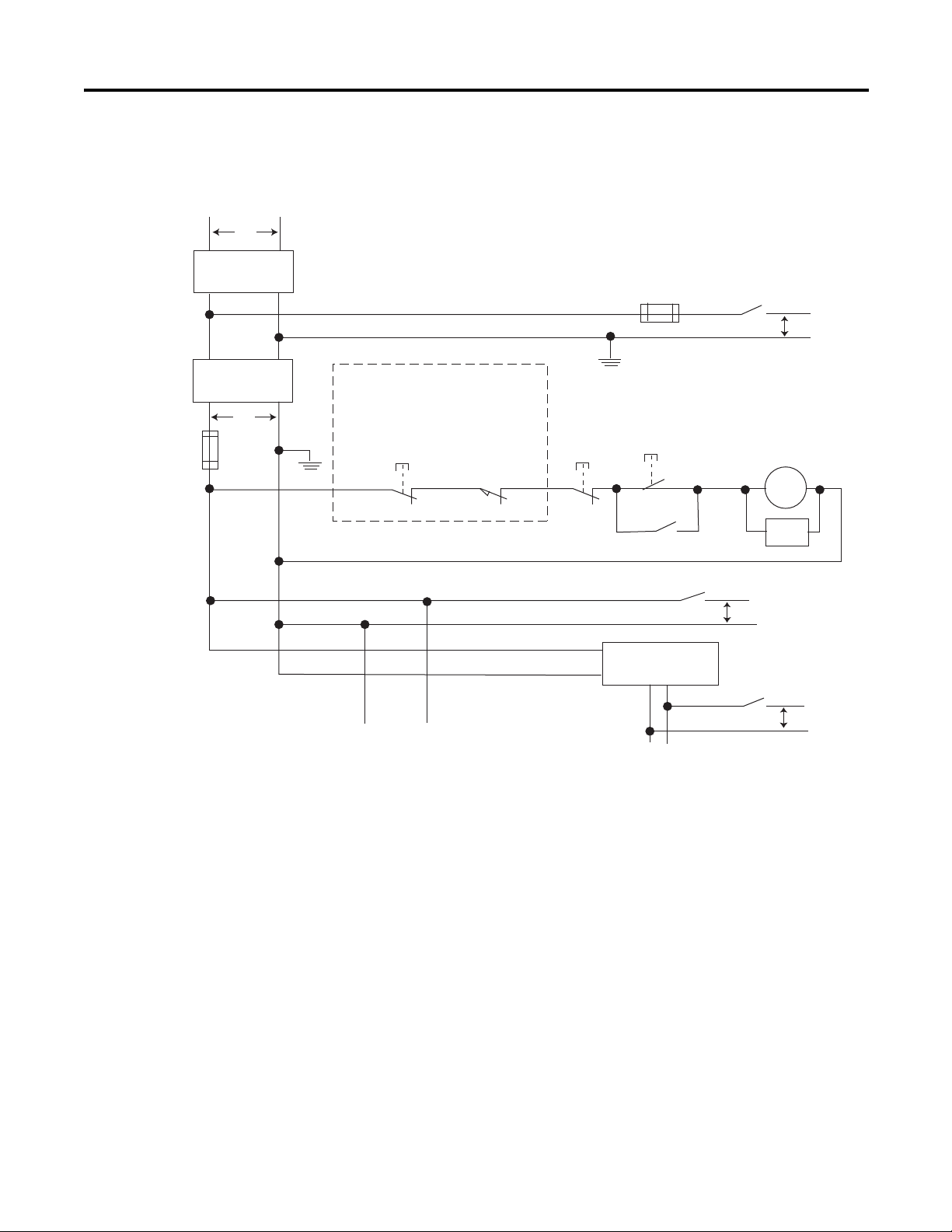
Schematic (Using IEC Symbols)
Disconnect
Isolation
Tr an sf or me r
Emergency-Stop
Push Button
Fuse MCR
230V AC
I/O
Circuits
Operation of either of these contacts will
remove power from the external I/O
circuits, stopping machine motion.
Fuse
Overtravel
Limit Switch
MCR
MCR
MCR
Stop Start
Line Terminals: Connect to terminals of Power
Supply
115V AC or
230V AC
I/O Circuits
L1
L2
230V AC
Master Control Relay (MCR)
Cat. No. 700-PK400A1
Suppressor
Cat. No. 700-N24
MCR
Suppr.
24V DC
I/O
Circuits
(Lo)
(Hi)
DC Power Supply.
Use IEC 950/EN 60950
X1 X2
115V AC
or 230V AC
Line Terminals: Connect to 24V DC terminals of
Power Supply
_
+
44564
About Your Controller Chapter 2
Rockwell Automation Publication 2080-UM005A-EN-E - December 2013 17
Page 26
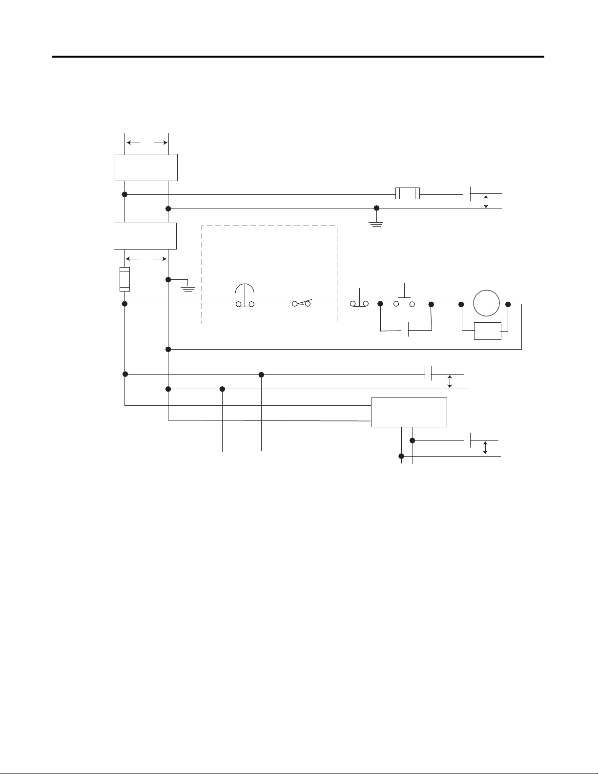
Chapter 2 About Your Controller
Emergency-Stop
Push Button
230V AC
Operation of either of these contacts will
remove power from the external I/O
circuits, stopping machine motion.
Fuse MCR
Fuse
MCR
MCR
MCR
Stop
Start
Line Terminals: Connect to terminals of Power
Supply
Line Terminals: Connect to 24V DC terminals of
Power Supply
230V AC
Output
Circuits
Disconnect
Isolation
Transformer
115V AC or
230V AC
I/O Circuits
L1
L2
Master Control Relay (MCR)
Cat. No. 700-PK400A1
Suppressor
Cat. No. 700-N24
(Lo)
(Hi)
DC Power Supply. Use
NEC Class 2 for UL
Listing
.
X1 X2
115V AC or
230V AC
_
+
MCR
24 V DC
I/O
Circuits
Suppr.
Overtravel
Limit Switch
44565
Schematic (Using ANSI/CSA Symbols)
18 Rockwell Automation Publication 2080-UM005A-EN-E - December 2013
Page 27
Chapter
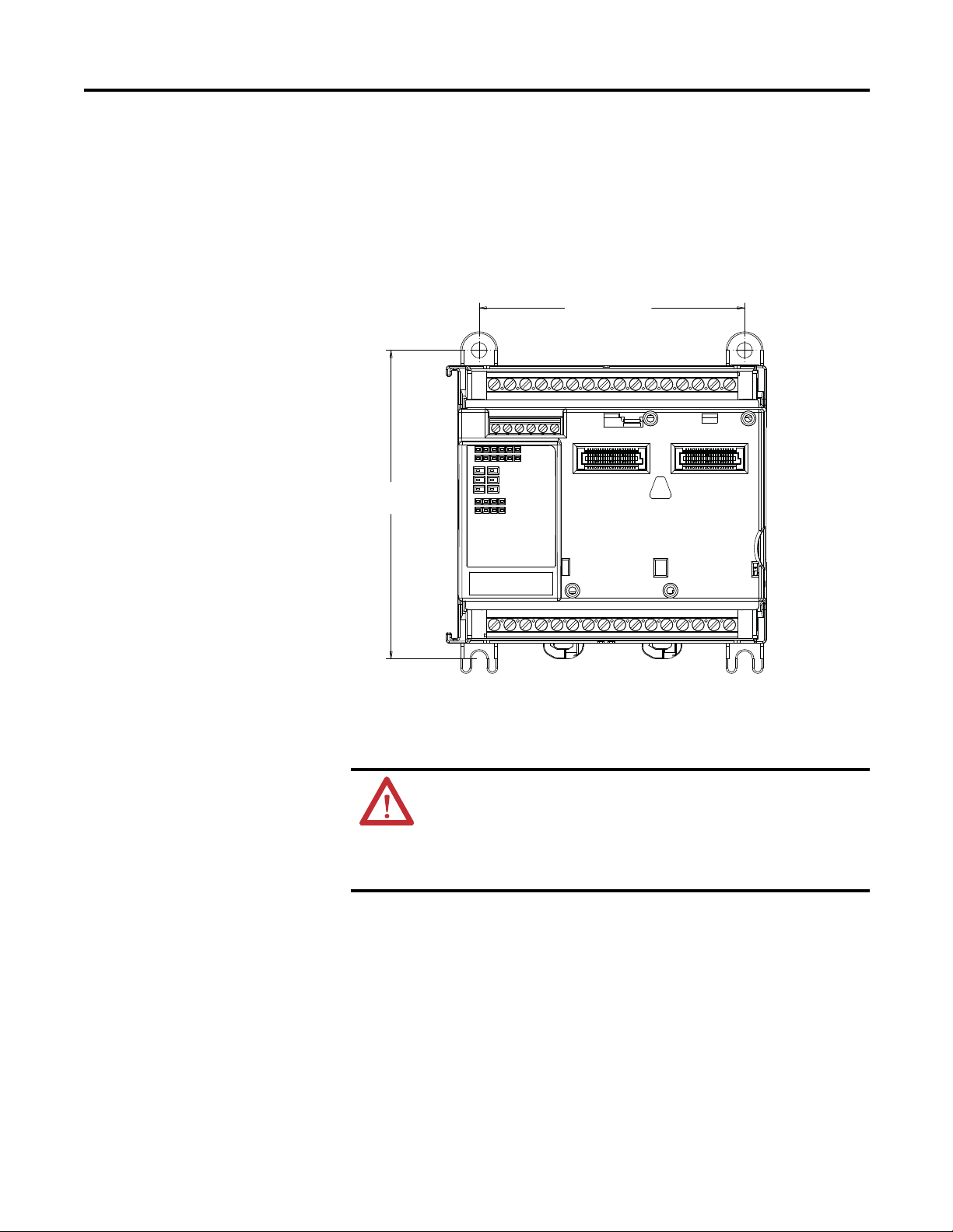
46205
Measurements in millimeters (inches)
104 (4.09)
75 (2.95)
90 (3.54)
3
Install Your Controller
This chapter serves to guide the user on installing the controller. It includes the
following topics.
Topic Page
Controller Mounting Dimensions 19
Connect the Controller to an EtherNet/IP Network 21
Module Spacing 20
DIN Rail Mounting 20
Panel Mounting 20
Panel Mounting Dimensions 21
Install the microSD Card 22
Install the 2080-REMLCD Module 23
Controller Mounting Dimensions
Mounting dimensions do not include mounting feet or DIN rail latches.
Rockwell Automation Publication 2080-UM005A-EN-E - December 2013 19
Page 28

Chapter 3 Install Your Controller
TIP
Module Spacing
Maintain spacing from enclosure walls, wireways, and adjacent equipment. Allow
50.8 mm (2 in.) of space on all sides. This provides ventilation and electrical
isolation. If optional accessories/modules are attached to the controller, such as
the power supply 2080-PS120-240VAC or expansion I/O modules, make sure
that there is 50.8 mm (2 in.) of space on all sides after attaching the optional
parts.
DIN Rail Mounting
The module can be mounted using the following DIN rails: 35 x 7.5 x 1 mm and
35 x 15 mm (EN 50 022 - 35 x 7.5 and EN 50 022 - 35 x 15).
For environments with greater vibration and shock concerns, use the
panel mounting method, instead of DIN rail mounting.
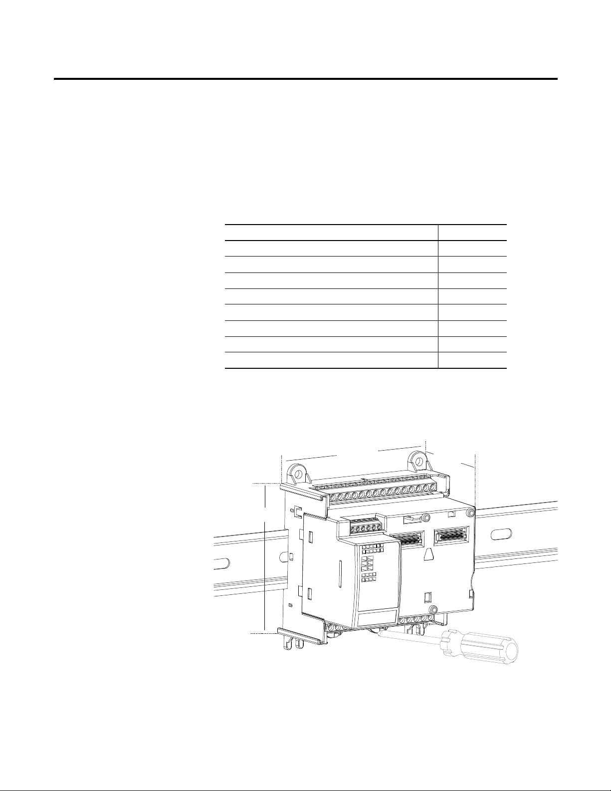
Before mounting the module on a DIN rail, use a flat-blade screwdriver in the
DIN rail latch and pry it downwards until it is in the unlatched position.
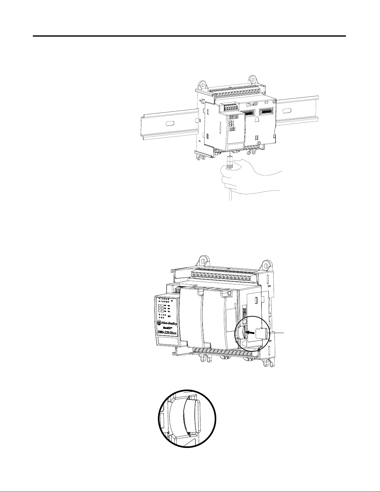
1. Hook the top of the DIN rail mounting area of the controller onto the
DIN rail, and then press the bottom until the controller snaps onto the
DIN rail.
2. Push the DIN rail latch back into the latched position.
Use DIN rail end anchors (Allen-Bradley part number 1492-EAJ35 or
1492-EAHJ35) for vibration or shock environments.
To remove your controller from the DIN rail, pry the DIN rail latch downwards
until it is in the unlatched position.
Panel Mounting
The preferred mounting method is to use four M4 (#8) screws per module. Hole
spacing tolerance: ±0.4 mm (0.016 in.).
Follow these steps to install your controller using mounting screws.
1. Place the controller against the panel where you are mounting it. Make sure
the controller is spaced properly.
2. Mark drilling holes through the mounting screw holes and mounting feet
then remove the controller.
3. Drill the holes at the markings, then replace the controller and mount it.
Leave the protective debris strip in place until you are finished wiring the
controller and any other devices.
20 Rockwell Automation Publication 2080-UM005A-EN-E - December 2013
Page 29
Install Your Controller Chapter 3
46204
86 mm (3.39 in.)
100 mm
(3.94 in.)
Panel Mounting Dimensions
Micro820 20-point controllers
2080-LC20-20AWB, 2080-LC20-20QWB, 2080-LC20-20QBB
2080-LC20-20AWBR, 2080-LC20-20QWBR, 2080-LC20-20QBBR
Connect the Controller to an EtherNet/IP Network
Rockwell Automation Publication 2080-UM005A-EN-E - December 2013 21
WARNING: If you connect or disconnect the communications cable with
power applied to this module or any device on the network, an electrical
arc can occur. This could cause an explosion in hazardous location
installations.
Be sure that power is removed or the area is nonhazardous before
proceeding.
Page 30
Chapter 3 Install Your Controller
46214
Insert the microSD
card into the slot.
46218
46219
Connect the RJ-45 connector of the Ethernet cable to the Ethernet port on the
controller. The port is on the bottom of the controller.
Install the microSD Card
1. Insert the microSD card into the card slot.
You can install the microSD card in one orientation only. The beveled
corner should be at the bottom. If you feel resistance when inserting the
microSD card, pull it out and change the orientation.
2. Gently press the card until it clicks into place.
22 Rockwell Automation Publication 2080-UM005A-EN-E - December 2013
Page 31

Install Your Controller Chapter 3
3. To remove the microSD card from the slot, gently press the card until it
clicks back and releases itself from the slot.
Install the 2080-REMLCD Module
The Micro820 controller supports the 2080-REMLCD module, a simple text
display interface for configuring settings such as IP address. It can be mounted
through a front panel or on the same DIN rail as the controller.
For information on how the Remote LCD interfaces with the Micro820
controller, see Using the Micro800 Remote LCD
To learn about installation, hardware features, and specifications of the
2080-REMLCD module, refer to the Installation Instructions, publication
2080-IN010
in the Literature Library.
on page 63.
Rockwell Automation Publication 2080-UM005A-EN-E - December 2013 23
Page 32

Chapter 3 Install Your Controller
Notes:
24 Rockwell Automation Publication 2080-UM005A-EN-E - December 2013
Page 33

Chapter
TIP
Wire Your Controller
This chapter provides information on the Micro820 controller wiring
requirements. It includes the following sections:
Topic Page
Wiring Requirements and Recommendation 25
Use Surge Suppressors 26
Recommended Surge Suppressors 28
Grounding the Controller 29
Wiring Diagrams 29
Controller I/O Wiring 30
Minimize Electrical Noise 31
Analog Channel Wiring Guidelines 31
Minimize Electrical Noise on Analog Channels 31
Grounding Your Analog Cable 32
Wiring Examples 32
4
Wiring Requirements and Recommendation
WARNING: Before you install and wire any device, disconnect power to
the controller system.
WARNING: Calculate the maximum possible current in each power and
common wire. Observe all electrical codes dictating the maximum
current allowable for each wire size. Current above the maximum ratings
may cause wiring to overheat, which can cause damage.
United States Only: If the controller is installed within a potentially
hazardous environment, all wiring must comply with the requirements
stated in the National Electrical Code 501-10 (b).
• Allow for at least 50 mm (2 in.) between I/O wiring ducts or terminal
strips and the controller.
• Route incoming power to the controller by a path separate from the device
wiring. Where paths must cross, their intersection should be
perpendicular.
Do not run signal or communications wiring and power wiring in the
same conduit. Wires with different signal characteristics should be
routed by separate paths.
Rockwell Automation Publication 2080-UM005A-EN-E - December 2013 25
Page 34

Chapter 4 Wire Your Controller
• Separate wiring by signal type. Bundle wiring with similar electrical
characteristics together.
• Separate input wiring from output wiring.
• Label wiring to all devices in the system. Use tape, shrink-tubing, or other
dependable means for labeling purposes. In addition to labeling, use
colored insulation to identify wiring based on signal characteristics. For
example, you may use blue for DC wiring and red for AC wiring.
Wire Requirements
Wire Requirements for fixed terminal blocks
Min Max
Solid 0.14 mm2 (26 AWG) 2.5 mm2 (14 AWG) rated @ 90 °C (194 °F ) insulation
Stranded 0.14 mm2 (26 AWG) 1.5 mm2 (16 AWG)
Wire requirements for removable terminal blocks
max
Use Surge Suppressors
Min Max
Solid and Stranded 0.2 mm2 (24 AWG) 2.5 mm2 (14 AWG) rated @ 90 °C (194 °F )
Wire requirements for RS232/RS485 serial port terminal block
Min Max
Solid 0.14 mm2 (26 AWG) 1.5 mm2 (16 AWG) rated @ 90 °C (194 °F)
Stranded 0.14 mm
2
(26 AWG) 1.0 mm2 (18 AWG)
insulation max
insulation max
Because of the potentially high current surges that occur when switching
inductive load devices, such as motor starters and solenoids, the use of some type
of surge suppression to protect and extend the operating life of the controllers
output contacts is required. Switching inductive loads without surge suppression
can significantly reduce the life expectancy of relay contacts. By adding a
suppression device directly across the coil of an inductive device, you prolong the
life of the output or relay contacts. You also reduce the effects of voltage
transients and electrical noise from radiating into adjacent systems.
26 Rockwell Automation Publication 2080-UM005A-EN-E - December 2013
Page 35

Wire Your Controller Chapter 4
+DC or L1
Suppression
device
DC COM or L2
AC or DC
outputs
Load
VAC/DC
Out 0
Out 1
Out 2
Out 3
Out 4
Out 5
Out
6
COM
+24V DC
IN4004 diode
Relay or solid
state DC outputs
24V DC common
VAC/DC
Out 0
Out 1
Out 2
Out 3
Out 4
Out 5
Out 6
COM
A surge suppressor
can also be used.
The following diagram shows an output with a suppression device. We
recommend that you locate the suppression device as close as possible to the load
device.
If the outputs are DC, we recommend that you use an 1N4004 diode for surge
suppression, as shown below. For inductive DC load devices, a diode is suitable. A
1N4004 diode is acceptable for most applications. A surge suppressor can also be
used. See Recommended Surge Suppressors
on page28. As shown below, these
surge suppression circuits connect directly across the load device.
Rockwell Automation Publication 2080-UM005A-EN-E - December 2013 27
Suitable surge suppression methods for inductive AC load devices include a
varistor, an RC network, or an Allen-Bradley surge suppressor, all shown below.
These components must be appropriately rated to suppress the switching
Page 36

Chapter 4 Wire Your Controller
Surge Suppression for Inductive AC Load Devices
Output device Output deviceOutput device
Varistor
RC network
Surge
suppressor
transient characteristic of the particular inductive device. See Recommended
Surge Suppressors on page28 for recommended suppressors.
Recommended Surge Suppressors
Use the Allen-Bradley surge suppressors in the following table for use with relays,
contactors, and starters.
Recommended Surge Suppressors
Device Coil Voltage Suppressor Catalog Number
Ty pe
Bulletin 100/104K 700K 24…48V AC 100-KFSC50 RC
110…280V AC 100-KFSC280
380…480V AC 100-KFSC480
12…55 V AC, 12…77V DC 100-KFSV55 MOV
56…136 VAC, 78…180V DC 100-KFSV136
137…277V AC, 181…250 V DC 100-KFSV277
12…250V DC 100-KFSD250 Diode
Bulletin 100C, (C09 - C97) 24…48V AC
110…280V AC
380…480V AC
12…55V AC, 12…77V DC
56…136V AC, 78…180V DC
137…277V AC, 181…250V DC
278…575V AC
12…250V DC
100-FSC48
100-FSC280
100-FSC480
100-FSV55
100-FSV136
100-FSV277
100-FSV575
100-FSD250
(1)
(1)
(1)
(1)
(1)
(1)
(1)
(1)
RC
MOV
Diode
Bulletin 509 Motor Starter Size 0 - 5 12…120V AC 599-K04 MOV
(4)
240…264V AC 599-KA04
28 Rockwell Automation Publication 2080-UM005A-EN-E - December 2013
Page 37

Recommended Surge Suppressors
Wire Your Controller Chapter 4
Device Coil Voltage Suppressor Catalog Number
Bulletin 509 Motor Starter Size 6 12…120V AC
12…120V AC
Bulletin 700 R/RM Relay AC coil Not Required
24…48V DC 199-FSMA9 MOV
50…120V DC 199-FSMA10
130…250V DC 199-FSMA11
Bulletin 700 Type N, P, PK or PH Relay 6…150V AC/DC 700-N24 RC
24…48V AC/DC 199-FSMA9 MOV
50…120V AC/DC 199-FSMA10
130…250V AC/DC 199-FSMA11
6…300V DC 199-FSMZ-1 Diode
Miscellaneous electromagnetic devices
limted to 35 sealed VA
(1) Catalog numbers for screwless terminals include the string ’CR’ after ’100-’. For example: Cat. No. 100-FSC48 becomes Cat. No. 100-CRFSC48; Cat. No. 100-FSV55
becomes 100-CRFSV55; and so on.
(2) For use on the interposing relay.
(3) For use on the contactor or starter.
(4) RC Type not to be used with Triac outputs. Varistor is not recommended for use on the relay outputs.
6…150V AC/DC 700-N24 RC
199-FSMA1
199-GSMA1
(2)
(3)
Ty pe
RC
MOV
(4)
Grounding the Controller
Wiring Diagrams
WARNING: All devices connected to the RS232/RS485
communication port must be referenced to controller ground, or be
floating (not referenced to a potential other than ground). Failure to
follow this procedure may result in property damage or personal injury.
This product is intended to be mounted to a well grounded mounting surface
such as a metal panel. Refer to the Industrial Automation Wiring and Grounding
Guidelines, publication 1770-4.1
, for additional information.
The following illustrations show the wiring diagrams for the Micro800
controllers. Controllers with DC inputs can be wired as either sinking or sourcing
inputs. Sinking and sourcing does not apply to AC inputs.
High-speed inputs and outputs are indicated by .
Rockwell Automation Publication 2080-UM005A-EN-E - December 2013 29
Page 38

Chapter 4 Wire Your Controller
46212
Input Terminal Block
Output Terminal Block
46211
Input Terminal Block
Output Terminal Block
D-
D+ G
Rx
Tx
12345
6
G
(View into terminal block)
Pin 1 RS485 Data +
Pin 2 RS485 Data -
Pin3 RS485 Ground
(1)
Pin 4 RS232 Receive
Pin 5 RS232 Transmit
Pin 6 RS232 Ground
(1)
(1) Non-isolated.
46213
2080-LC20-20AWB, 2080-LC20-20QWB, 2080-LC20-20AWBR, 2080-LC20- 20QWBR
+DC10 I-00
I-02
COM0
I-05
123456789101112
-DC24
+DC24 -DC24
I-01
I-03
NU
O-00
I-04
I-06
O-01
123456789101112
VO-0-DC24
CM0
CM1 CM2
ATTENTION: For 2080-LC20-20AWB/R catalogs, inputs 00…03 are
limited to 24V DC. All other inputs (04…11) are limited to 120V AC.
2080-LC20-20QBB / 2080-LC20-20QBBR
+DC10 I-00
123456789101112
-DC24
+DC24 -DC24
123456789101112
I-02
I-01
NU
VO-0-DC24
I-03
+CM0
COM0
I-04
O-00
O-01 O-03
I-05
I-06
O-02
I-07
O-02
I-07
-CM0
I-09
13 14 15 16
I-08
CM3
13 14 15 16
O-03
I-09
13 14 15 16
I-08
O-04
13 14 15 16
+CM1
I-10
O-04
I-10
O-05
I-11
NU
O-05
O-06
I-11
NU
O-06
-CM1
Controller I/O Wiring
30 Rockwell Automation Publication 2080-UM005A-EN-E - December 2013
Serial Port Terminal Block
This section contains some relevant information about minimizing electrical
noise and also includes some wiring examples.
Page 39

Wire Your Controller Chapter 4
Minimize Electrical Noise
Because of the variety of applications and environments where controllers are
installed and operating, it is impossible to ensure that all environmental noise will
be removed by input filters. To help reduce the effects of environmental noise,
install the Micro800 system in a properly rated (for example, NEMA) enclosure.
Make sure that the Micro800 system is properly grounded.
A system may malfunction due to a change in the operating environment after a
period of time. We recommend periodically checking system operation,
particularly when new machinery or other noise sources are installed near the
Micro800 system.
Analog Channel Wiring Guidelines
Consider the following when wiring your analog channels:
• The analog common (-DC24) is not electrically isolated from the system,
and is connected to the power supply common.
• Analog channels are not isolated from each other.
• Use Belden cable #8761, or equivalent, shielded wire.
• Under normal conditions, the drain wire (shield) should be connected to
the metal mounting panel (earth ground). Keep the shield connection to
earth ground as short as possible.
• To ensure optimum accuracy for voltage type inputs, limit overall cable
impedance by keeping all analog cables as short as possible. Locate the I/O
system as close to your voltage type sensors or actuators as possible.
Minimize Electrical Noise on Analog Channels
Inputs on analog channels employ digital high-frequency filters that significantly
reduce the effects of electrical noise on input signals. However, because of the
variety of applications and environments where analog controllers are installed
and operated, it is impossible to ensure that all environmental noise will be
removed by the input filters.
Several specific steps can be taken to help reduce the effects of environmental
noise on analog signals:
• install the Micro800 system in a properly rated enclosure, for example,
NEMA/IP. Make sure that the shield is properly grounded.
• use Belden cable #8761 for wiring the analog channels, making sure that
the drain wire and foil shield are properly earth grounded.
• route the Belden cable separately from any AC wiring. Additional noise
immunity can be obtained by routing the cables in grounded conduit.
Rockwell Automation Publication 2080-UM005A-EN-E - December 2013 31
Page 40

Chapter 4 Wire Your Controller
IMPORTANT
Foil shield
Black wire
Drain wire
Clear wire
Insulation
44531
Com
Fuse
24V
DC
I/P
+
~
45627
Grounding Your Analog Cable
Use shielded communication cable (Belden #8761). The Belden cable has two
signal wires (black and clear), one drain wire, and a foil shield. The drain wire and
foil shield must be grounded at one end of the cable.
Do not ground the drain wire and foil shield at both ends of the cable.
Wiring Examples
Examples of sink/source, input/output wiring are shown below.
Sink Input Wiring Example
32 Rockwell Automation Publication 2080-UM005A-EN-E - December 2013
Page 41

Source Output Wiring Example
D
DC COM
OUT
+V DC
S
G
Logic side
User side
+
–
24V Supply
Load
Fuse
45626
IMPORTANT
Com
Fuse
24V
DC
I/P
+
~
45625
For 2080-LC20-20QBB(R) discrete output 06, shielded cable is required if
the output is used as PWM. Otherwise, unshielded cable can be used.
Wire Your Controller Chapter 4
Wiring Analog Channels
Source Input Wiring Example
Analog input circuits can monitor voltage signals and convert them to serial
digital data as shown in the following illustration.
ATTENTION: Analog inputs and outputs are not isolated.
Rockwell Automation Publication 2080-UM005A-EN-E - December 2013 33
Page 42

Chapter 4 Wire Your Controller
46254
Note: Terminal block to wire
commons is not included in
Micro800 package.
-DC24
+DC10 I-00
I-01
I-02
I-03
COM0
I-04
I-05
I-08
I-07
123456789101112
I-10
I-09NUI-11
13 14 15 16
I-06
Thermistor 3
Thermistor 2
Thermistor 1
Thermistor 0
1234
1234
46255
Note: Terminal block to wire
commons is not included in
Micro800 package.
Analog input to sensors
Sensor 3
(V ) Voltage
Sensor 2
(V ) Voltage
Sensor 1
(V ) Voltage
Sensor 0
(V ) Voltage
1234
1234
Analog input to thermistors
+DC10 I-00
123456789101112
-DC24
I-02
COM0
I-05
I-07
I-01
I-03
I-04
I-08
I-06
I-09NUI-11
13 14 15 16
I-10
34 Rockwell Automation Publication 2080-UM005A-EN-E - December 2013
Page 43

Wire Your Controller Chapter 4
IMPORTANT
Vi =
Ri + Rt
Ri
*
Vref
Rt=
Vi
Vi Vref - Vi Ri
Calculate for Thermistor Resistance
While connecting Analog input to thermistor as shown in previous diagram,
calculate input voltage using the following equation:
Where:
Vi = Voltage input (±5% without calibration; ±2% with calibration)
Ri = Resistance input (14.14 KΩ ±2%)
Rt = Thermistor resistance (10 KΩ Thermistor is recommended)
Vref = 10V ±0.5V
To calculate for thermistor resistance, use the following equation.
Micro820 controllers support 10 KΩ type thermistors.
In order to get the best results, the system must be calibrated.
Calibrate Thermistor
1. Connect a resistor (10 KΩ is recommended) across Vref and Analog
Input 00 of your Micro820 controller following the diagram, Analog input
to thermistors on page34. The resistor is measured as Ri using a precision
multimeter.
2. Calculate the ideal counts (C1) for resistor (Ri) following this equation:
C1 = 14.14 KΩ / (14.14 KΩ + Ri) * 4095
3. Read the actual counts (C2) of Analog Input 00 from Connected
Components Workbench.
4. Calculate for calibration Gain.
Gain = C1/C2
For example :
If Ri is measured as 10.00 KΩ, then
C1 = 14.14 / (14.14 + 10.00) * 4095 = 2399 counts;
C2 is read from Connected Components Workbench as 2440; so
Gain = 2399/2440 = 98% .
Rockwell Automation Publication 2080-UM005A-EN-E - December 2013 35
Page 44

Chapter 4 Wire Your Controller
Power
Supply
+
–
2-wire Transmitter
+
–
Supply
GND
Signal
Controller
I-00, I-01, I-02 or I-03
-DC24
+
–
Controller
I-00, I-01, I-02 or I-03
-DC24
Supply
Signal
+
–
Controller
I-00, I-01, I-02 or I-03
-DC24
+
+
–
–
3-wire Transmitter
4-wire Transmitter
Power
Supply
Power
Supply
46257
Voltage
Load
+DC24 -DC24
VO-0-DC24
NU
CM0
O-00
CM1 CM2
O-01
O-03
O-02
123456789101112
O-04
CM3
O-06
O-05
13 14 15 16
46256
5. In Connected Components Workbench, go to Embedded I/O
configuration page. Change the Gain parameter value for Input 00 to 98.
No changes are required to the Offset parameter value.
6. Repeat the same steps to calibrate all the other analog input channels.
Analog Input to Transmitters
Analog Output
The analog output can support voltage function as shown in the following
illustration.
36 Rockwell Automation Publication 2080-UM005A-EN-E - December 2013
Page 45

Communication Connections
Chapter
5
Overview
Supported Communication Protocols
This chapter describes how to communicate with your control system and
configure communication settings. The method you use and cabling required to
connect your controller depends on what type of system you are employing. This
chapter also describes how the controller establishes communication with the
appropriate network. Topics include:
Topic Page
Supported Communication Protocols 37
Use Modems with Micro800 Controllers 41
Configure Serial Port 42
Configure Ethernet Settings 48
The Micro820 controllers have the following embedded communication
channels:
• a non-isolated RS232/RS485 combo port
• RJ45 Ethernet port
Micro820 controllers support the following communication protocols through
the embedded RS232/RS485 serial port as well as any installed serial port plug-in
modules:
• Modbus RTU Master and Slave
• CIP Serial Client/Server (RS232 only)
• ASCII
In addition, the embedded Ethernet communication channel allows your
Micro820 controller to be connected to a local area network for various devices
providing 10 Mbps/100 Mbps transfer rate. Micro820 controllers support the
following Ethernet protocols:
• EtherNet/IP Client/Server
• Modbus/TCP Client/Server
• DHCP Client
Modbus RTU
Modbus is a half-duplex, master-slave communications protocol. The Modbus
network master reads and writes bits and registers. Modbus protocol allows a
Rockwell Automation Publication 2080-UM005A-EN-E - December 2013 37
Page 46

Chapter 5 Communication Connections
TIP
TIP
single master to communicate with a maximum of 247 slave devices. Micro800
controllers support Modbus RTU Master and Modbus RTU Slave protocol. For
more information on configuring your Micro800 controller for Modbus
protocol, refer to the Connected Components Workbench Online Help. For
more information about the Modbus protocol, refer to the Modbus Protocol
Specifications (available from http://www.modbus.org
).
See Modbus Mapping for Micro800 on page 249
for information on Modbus
mapping. To configure the Serial port as Modbus RTU, see Configure Modbus
RTU on page 45.
Use MSG_MODBUS instruction to send Modbus messages over
serial port.
Modbus/TCP Client/Server
The Modbus/TCP Client/Server communication protocol uses the same
Modbus mapping features as Modbus RTU, but instead of the Serial port, it is
supported over Ethernet. Modbus/TCP Server takes on Modbus Slave features
on Ethernet.
The Micro820 controller supports up to 16 simultaneous Modbus TCP Client
connections and 16 simultaneous Modbus TCP Server connections.
No protocol configuration is required other than configuring the Modbus
mapping table. For information on Modbus mapping, see Modbus Mapping for
Micro800 on page 249.
Use MSG_MODBUS2 instruction to send Modbus TCP message over
Ethernet port.
CIP Symbolic Client/Server
CIP Symbolic is supported by any CIP compliant interface including Ethernet
(EtherNet/IP) and Serial Port (CIP Serial). This protocol allows HMIs to easily
connect to the Micro820 controller.
CIP Serial, supported on the Micro820 controller, makes use of DF1 Full Duplex
protocol, which provides point-to-point connection between two devices.
The Micro800 controllers support the protocol through RS232 connection to
external devices, such as computers running RSLinx Classic software, PanelView
Component terminals (firmware revisions 1.70 and above), or other controllers
that support CIP Serial over DF1 Full-Duplex, such as ControlLogix and
CompactLogix controllers that have embedded serial ports.
38 Rockwell Automation Publication 2080-UM005A-EN-E - December 2013
Page 47

Communication Connections Chapter 5
EtherNet/IP, supported on the Micro820 controller, makes use of the standard
Ethernet TCP/IP protocol. The Micro820 controller supports up to 16
simultaneous EtherNet/IP Client connections and 16 simultaneous EtherNet/IP
Server connections.
To configure CIP Serial, see Configure CIP Serial Driver
To configure for EtherNet/IP, see Configure Ethernet Settings
on page 43.
on page 48.
CIP Symbolic Addressing
Users may access any global variable through CIP Symbolic addressing except for
system and reserved variables.
One- or two-dimension arrays for simple data types are supported (for example,
ARRAY OF INT[1..10, 1..10]) are supported but arrays of arrays (for example,
ARRAY OF ARRAY) are not supported. Array of strings are also supported.
Supported Data Types in CIP Symbolic
Data Type
BOOL Logical Boolean with values TRUE and FALSE
SINT Signed 8-bit integer value
INT Signed 16-bit integer value
DINT Signed 32-bit integer value
LINT
USINT Unsigned 8-bit integer value
UINT Unsigned 16-bit integer value
UDINT Unsigned 32-bit integer value
ULINT
REAL 32-bit floating point value
LREAL
STRING character string (1 byte per character)
(1)
(2)
(1)
(2)
(2)
(2)
Logix MSG instruction can read/write SINT, INT, DINT, LINT and REAL datatypes using "CIP
Data Table Read" and "CIP Data Table Write" message types.
BOOL, USINT, UINT, UDINT, ULINT, LREAL, STRING and SHORT_STRING datatypes are not
accessible with the Logix MSG instruction.
Not supported in PanelView Component.
Description
Signed 64-bit integer value
Unsigned 64-bit integer value
64-bit floating point value
CIP Client Messaging
CIP Generic and CIP Symbolic messages are supported on Micro800 controllers
through the Ethernet and serial ports. These client messaging features are enabled
by the MSG_CIPSYMBOLIC and MSG_CIPGENERIC function blocks.
Rockwell Automation Publication 2080-UM005A-EN-E - December 2013 39
Page 48

Chapter 5 Communication Connections
The user can download a program from the PC to controller1 through the
USB to serial port conversion via the Remote LCD. Also, the program can
be downloaded to controller2 and controller3 over USB to EtherNet/IP but
the performance is limited by the serial connection.
45921
See Micro800 Programmable Controllers: Getting Started with CIP Client
Messaging, publication 2080-QS002
, for more information and sample
quickstart projects to help you use the CIP Client Messaging feature.
ASCII
ASCII provides connection to other ASCII devices, such as bar code readers,
weigh scales, serial printers, and other intelligent devices. You can use ASCII by
configuring the embedded or any plug-in serial RS232 or RS485 port for the
ASCII driver. Refer to the Connected Components Workbench Online Help for
more information.
CIP Communications Pass-thru
To configure the serial port for ASCII, see Configure ASCII
on page 47.
The Micro820 controllers support pass-thru on any communications port that
supports Common Industrial Protocol (CIP). The maximum number of
supported hops is one. A hop is defined to be an intermediate connection or
communications link between two devices – in Micro800, this is through
EtherNet/IP or CIP Serial.
Examples of Supported Architectures
CIP Serial to EtherNet/IP
USB
F3
F1 F2
F5
F6
F4
MENU
REMLCD
Serial
ESC
OK
Micro820
Controller1
EtherNet/IP
Micro820
Controller2
Micro820
Controller3
40 Rockwell Automation Publication 2080-UM005A-EN-E - December 2013
Page 49

EtherNet/IP to CIP Serial
EtherNet/IP
CIP Serial
Micro820
Controller
Micro820
Controller
46046
IMPORTANT
DTE Device
(Micro820
Channel 0)
DCE Device
(Modem, etc.)
niP-9niP-52niP-6
32DXTDXT5
23DXRDXR4
57DNGDNG6
18DCD)+(B1
402RTD)-(A2
66RSD3
85STC
74STR
DNG
Micro800 controllers do not support more than one hop (for example,
from EtherNet/IP → CIP Serial → EtherNet/IP).
Communication Connections Chapter 5
Use Modems with Micro800 Controllers
Serial modems can be used with the Micro820 controllers.
Making a DF1 Point-to-Point Connection
You can connect the Micro820 programmable controller to your serial modem.
The recommended protocol for this is Modbus RTU.
Construct Your Own Modem Cable
If you construct your own modem cable, the maximum cable length is 3 m (10 ft)
with a 25-pin or 9-pin connector. Refer to the following typical pinout for
constructing a straight-through cable:
Rockwell Automation Publication 2080-UM005A-EN-E - December 2013 41
Page 50

Chapter 5 Communication Connections
uncheck this option
Configure Serial Port
You can configure the Serial Port driver as CIP Serial, Modbus RTU, ASCII or
choose Shutdown through the Controller Configuration tree in Connected
Components Workbench software.
By default, when a Micro820 controller is added to the Project Organizer in
Connected Components Workbench, Remote LCD parameters are configured
to overwrite serial port settings.
To edit serial port settings, go to the Remote LCD configuration page and
uncheck the Configure Serial Port for Remote LCD option button.
42 Rockwell Automation Publication 2080-UM005A-EN-E - December 2013
Page 51

Communication Connections Chapter 5
When the Remote LCD configuration is unchecked, the serial port values are
visible and can be edited.
Configure CIP Serial Driver
1. Open your Connected Components Workbench project. On the device
configuration tree, go to the Controller properties. Click Serial Port.
Rockwell Automation Publication 2080-UM005A-EN-E - December 2013 43
Page 52

Chapter 5 Communication Connections
2. Select CIP Serial from the Driver field.
3. Specify a baud rate. Select a communication rate that all devices in your
system support. Configure all devices in the system for the same
communication rate. Default baud rate is set @ 38400 bps.
4. In most cases, parity and station address should be left at default settings.
5. Click Advanced Settings and set Advanced parameters.
Refer to the table CIP Serial Driver Parameters
on page 44 for a
description of the CIP Serial parameters.
CIP Serial Driver Parameters
Parameter Options Default
Baud rate Toggles between the communication rate of 1200, 2400,
Parity Specifies the parity setting for the serial port. Parity
Station Address The station address for the serial port on the DF1
DF1 Mode DF1 Full Duplex (read only) Configured as
Control Line No Handshake (read only) Configured as no
Duplicate Packet
Detection
Error Detection Toggles between CRC and BCC. CRC
4800, 9600, 19200, and 38400.
provides additional message-packet error detection.
Select Even, Odd, or None.
master. The only valid address is 0…254.
Detects and eliminates duplicate responses to a
message. Duplicate packets may be sent under noisy
communication conditions when the sender’s retries are
not set to 0. Toggles between Enabled and Disabled.
38400
None
1
full-duplex by
default.
handshake by
default.
Enabled
44 Rockwell Automation Publication 2080-UM005A-EN-E - December 2013
Page 53

CIP Serial Driver Parameters
Communication Connections Chapter 5
Embedded
Responses
NAK Retries The number of times the controller will resend a
ENQ Retries The number of enquiries (ENQs) that you want the
Transmit Retries Specifies the number of times a message is retried after
ACK Timeout
(x20 ms)
To use embedded responses, choose Enabled
Unconditionally. If you want the controller to use
embedded responses only when it detects embedded
responses from another device, choose After One
Received.
If you are communicating with another Allen-Bradley
device, choose Enabled Unconditionally. Embedded
responses increase network traffic efficiency.
message packet because the processor received a NAK
response to the previous message packet transmission.
controller to send after an ACK timeout occurs.
the first attempt before being declared undeliverable.
Enter a value from 0…127.
Specifies the amount of time after a packet is
transmitted that an ACK is expected.
After One
Received
3
3
3
50
Configure Modbus RTU
1. Open your Connected Components Workbench project. On the device
configuration tree, go to the Controller properties. Click Serial Port.
Rockwell Automation Publication 2080-UM005A-EN-E - December 2013 45
Page 54

Chapter 5 Communication Connections
2. Select Modbus RTU on the Driver field.
3. Specify the following parameters:
• Baud rate
• Parity
• Unit address
• Modbus Role (Master, Slave, Auto)
Modbus RTU Parameters
Parameter Options Default
Baud Rate 1200, 2400, 4800, 9600, 19200, 38400 19200
Parity None, Odd, Even None
Modbus Role Master, Slave, Auto Master
4. Click Advanced Settings to set advanced parameters.
Refer to the table for available options and default configuration for
advanced parameters.
Modbus RTU Advanced Parameters
Parameter Options Default
Media RS-232, RS-232 RTS/CTS, RS-485 RS-232
Data bits Always 8 8
Stop bits 1, 2 1
Response timer 0…999,999,999 milliseconds 200
Broadcast Pause 0…999,999,999 milliseconds 200
Inter-char timeout 0…999,999,999 microseconds 0
RTS Pre-delay 0…999,999,999 microseconds 0
RTS Post-delay 0…999,999,999 microseconds 0
46 Rockwell Automation Publication 2080-UM005A-EN-E - December 2013
Page 55

Communication Connections Chapter 5
Configure ASCII
1. Open your Connected Components Workbench project. On the device
configuration tree, go to Controller properties. Click Serial Port.
2. Select ASCII on the Driver field.
3. Specify baud rate and parity.
ASCII Parameters
Parameter Options Default
Baud Rate 1200, 2400, 4800, 9600, 19200, 38400 19200
Parity None, Odd, Even None
Control Line RS485
No Handshake
Deletion Mode CRT
Ignore
Printer
Data Bits 7, 8 8
XON/XOFF Enabled or Disabled Disabled
Stop Bits 1, 2 1
Echo Mode Enabled or Disabled Disabled
Append Chars 0x0D,0x0A or user-specified value 0x0D,0x0A
Termination Chars 0x0D,0x0A or user-specified value 0x0D,0x0A
No Handshake
Ignore
Rockwell Automation Publication 2080-UM005A-EN-E - December 2013 47
Page 56

Chapter 5 Communication Connections
TIP
Configure Ethernet Settings
1. Open your Connected Components Workbench project (for example,
Micro820). On the device configuration tree, go to Controller properties.
Click Ethernet.
2. Under Ethernet, click Internet Protocol.
Configure Internet Protocol (IP) settings. Specify whether to obtain the
IP address automatically using DHCP or manually configure IP address,
subnet mask, and gateway address.
The Ethernet port defaults to the following out-of-the box settings:
• DHCP (dynamic IP address)
• Address Duplicate Detection: On
3. Click the checkbox Detect duplicate IP address to enable detection of
duplicate address.
4. Under Ethernet, click Port Settings.
5. Set Port State as Enabled or Disabled.
6. To manually set connection speed and duplexity, uncheck the option box
Auto-Negotiate speed and duplexity. Then, set Speed (10 or 100 Mbps)
and Duplexity (Half or Full) values.
48 Rockwell Automation Publication 2080-UM005A-EN-E - December 2013
Page 57

Communication Connections Chapter 5
7. Click Save Settings to Controller if you would like to save the settings to
your controller.
8. On the device configuration tree, under Ethernet, click Port Diagnostics to
monitor Interface and Media counters. The counters are available and
updated when the controller is in Debug mode.
Ethernet Host Name
Micro800 controllers implement unique host names for each controller, to be
used to identify the controller on the network. The default host name is
comprised of two parts: product type and MAC address, separated by a hyphen.
For example: 2080LC20-xxxxxxxxxxxx, where xxxxxxxxxxxx is the MAC
address.
The user can change the host name using the CIP Service Set Attribute Single
when the controller is in Program/Remote Program mode.
Rockwell Automation Publication 2080-UM005A-EN-E - December 2013 49
Page 58

Chapter 5 Communication Connections
Notes:
50 Rockwell Automation Publication 2080-UM005A-EN-E - December 2013
Page 59

Chapter
IMPORTANT
6
Program Execution in Micro800
This section provides a brief overview of running or executing programs with a
Micro800 controller.
This section generally describes program execution in Micro800
controllers. Certain elements may not be applicable or true in certain
models (for example, Micro820 does not support PTO motion control).
Overview of Program Execution
A Micro800 cycle or scan consists of reading inputs, executing programs in
sequential order, updating outputs and performing housekeeping (datalog, recipe,
communications).
Program names must begin with a letter or underscore, followed by up to 127
letters, digits or single underscores. Use programming languages such as ladder
logic, function block diagrams and structured text.
Up to 256 programs may be included in a project, depending on available
controller memory. By default, the programs are cyclic (executed once per cycle or
scan). As each new program is added to a project, it is assigned the next
consecutive order number. When you start up the Project Organizer in
Connected Components Workbench, it displays the program icons based on this
order. You can view and modify an order number for a program from the
program’s properties. However, the Project Organizer does not show the new
order until the next time the project is opened.
The Micro800 controller supports jumps within a program. Call a subroutine of
code within a program by encapsulating that code as a User Defined Function
Block (UDFB). Although a UDFB can be executed within another UDFB, a
maximum nesting depth of five is supported. A compilation error occurs if this is
exceeded.
Alternatively, you can assign a program to an available interrupt and have it
executed only when the interrupt is triggered. A program assigned to the User
Fault Routine runs once just prior to the controller going into Fault mode.
In addition to the User Fault Routine, Micro800 controllers also support two
Selectable Timed Interrupts (STI). STIs execute assigned programs once every
set point interval (1…65535 ms).
The Global System Variables associated with cycles/scans are:
• __SYSVA_CYCLECNT – Cycle counter
Rockwell Automation Publication 2080-UM005A-EN-E - December 2013 51
Page 60

Chapter 6 Program Execution in Micro800
1. Read inputs
2. Execute POUs
(1)
/programs
3. Writ e o ut put s
4. Housekeeping (datalog,
recipe, communications)
(1) Program Organizational Unit.
4
1
2
3
1
2
3
• __SYSVA_TCYCURRENT – Current cycle time
• __SYSVA_TCYMAXIMUM – Maximum cycle time since last start.
Execution Rules
This section illustrates the execution of a program. The execution follows four
main steps within a loop. The loop duration is a cycle time for a program.
Controller Load and Performance Considerations
When a cycle time is specified, a resource waits until this time has elapsed before
starting the execution of a new cycle. The POUs execution time varies depending
on the number of active instructions. When a cycle exceeds the specified time, the
loop continues to execute the cycle but sets an overrun flag. In such a case, the
application no longer runs in real time.
When a cycle time is not specified, a resource performs all steps in the loop then
restarts a new cycle without waiting.
Within one program scan cycle, the execution of the main steps (as indicated in
the Execution Rules diagram) could be interrupted by other controller activities
which have higher priority than the main steps. Such activities include,
1. User Interrupt events, including STI, EII, and HSC interrupts (when
applicable);
2. Communication data packet receiving and transmitting;
3. PTO Motion engine periodical execution (if supported by the controller).
When one or several of these activities occupy a significant percentage of the
Micro800 controller execution time, the program scan cycle time will be
prolonged. The Watchdog timeout fault (0xD011) could be reported if the
impact of these activities is underestimated, and the Watchdog timeout is set
52 Rockwell Automation Publication 2080-UM005A-EN-E - December 2013
Page 61

Program Execution in Micro800 Chapter 6
marginally. The Watchdog setting defaults to 2 s and generally never needs to be
changed.
Periodic Execution of Programs
For applications where periodic execution of programs with precise timing is
required, such as for PID, it is recommended that STI (Selectable Timed
Interrupt) be used to execute the program. STI provides precise time intervals.
It is not recommended that the system variable __SYSVA_TCYCYCTIME be
used to periodically execute all programs as this also causes all communication to
execute at this rate.
System Variable for Programmed Cycle Time
WARNING: Communication timeouts may occur if programmed cycle
time is set too slow (for example, 200 ms) to maintain communications.
Power Up and First Scan
Variable Type Description
__SYSVA_TCYCYCTIME TIME Programmed cycle time.
Note: Programmed cycle time only accepts values in
multiples of 10 ms. If the entered value is not a
multiple of 10, it will be rounded up to the next
multiple of 10.
On firmware revision 2 and later, all digital output variables driven by the I/O
scan gets cleared on powerup and during transition to RUN mode.
Two system variables are also available from revision 2 and later.
System Variables for Scan and Powerup on Firmware Release 2 and later
Variable Type Description
_SYSVA_FIRST_SCAN BOOL First scan bit.
Can be used to initialize or reset variables immediately
after every transition from Program to Run mode.
Note: True only on first scan. After that, it is false.
_SYSVA_POWER_UP_BIT BOOL Powerup bit.
Can be used to initialize or reset variables immediately
after download from Connected Components
Workbench or immediately after being loaded from
memory backup module (for example, microSD card).
Note:True only on the first scan after a powerup, or
running a new ladder for the first time.
Rockwell Automation Publication 2080-UM005A-EN-E - December 2013 53
Page 62

Chapter 6 Program Execution in Micro800
Variable Retention
Micro830 and Micro850 controllers retain all user-created variables after a power
cycle, but the variables inside instances of instructions are cleared. For example: A
user created variable called My_Timer of Time data type will be retained after a
power cycle but the elapsed time (ET) within a user created timer TON
instruction will be cleared.
Unlike Micro830/Micro850 controllers, Micro810 and Micro820 controllers
can only retain a maximum of 400 bytes of user-created variable values. This
means that after a power cycle, global variables are cleared or set to initial value,
and only 400 bytes of user-created variable values are retained. Retained variables
can be checked at the global variable page.
Memory Allocation
Depending on base size, available memory on Micro800 controllers are shown in
the table below.
Memory Allocation for Micro800 Controllers
Attribute 10/16-point 20-point 24- and 48-points
Program steps
Data bytes 8 KB 20 KB 20 KB
(1) Estimated Program and Data size are “typical” – program steps and variables are created dynamically.
1 Program Step = 12 data bytes.
(1)
4 K 10 K 10 K
These specifications for instruction and data size are typical numbers. When a
project is created for Micro800, memory is dynamically allocated as either
program or data memory at build time. This means that program size can exceed
the published specifications if data size is sacrificed and vice versa. This flexibility
allows maximum usage of execution memory. In addition to the user defined
variables, data memory also includes any constants and temporary variables
generated by the compiler at build time.
The Micro800 controllers also have project memory, which stores a copy of the
entire downloaded project (including comments), as well as configuration
memory for storing plug-in setup information, and so on.
Guidelines and Limitations for Advanced Users
54 Rockwell Automation Publication 2080-UM005A-EN-E - December 2013
Here are some guidelines and limitations to consider when programming a
Micro800 controller using Connected Components Workbench software:
Page 63

Program Execution in Micro800 Chapter 6
UDFB1
UDFB2
UDFB3
UDFB4
UDFB5
• Each program/POU can use up to 64 Kb of internal address space. It is
recommended that you split large programs into smaller programs to
improve code readability, simplify debugging and maintenance tasks.
• A User Defined Function Block (UDFB) can be executed within another
UDFB, with a limit of five nested UDFBs. Avoid creating UDFBs with
references to other UDFBs, as executing these UDFBs too many times may
result in a compile error.
Example of Five Nested UDFBs
• Structured Text (ST) is much more efficient and easier to use than Ladder
Logic, when used for equations. if you are used to using the RSLogix 500
CPT Compute instruction, ST combined with UDFB is a great
alternative.
As an example, for an Astronomical Clock Calculation, Structured Text
uses 40% less Instructions.
Display_Output LD:
Memory Usage (Code) : 3148 steps
Memory Usage (Data) : 3456 bytes
Display_Output ST:
Memory Usage (Code) : 1824 steps
Memory Usage (Data) : 3456 bytes
• You may encounter an Insufficient Reserved Memory error while
downloading and compiling a program over a certain size. One
workaround is to use arrays, especially if there are many variables.
Rockwell Automation Publication 2080-UM005A-EN-E - December 2013 55
Page 64

Chapter 6 Program Execution in Micro800
Notes:
56 Rockwell Automation Publication 2080-UM005A-EN-E - December 2013
Page 65

Chapter
TIP
Controller Security
Micro800 security generally has two components:
• Exclusive Access which prevents simultaneous configuration of the
controller by two users
• Controller Password Protection which secures the Intellectual Property
contained within the controller and prevents unauthorized access
7
Exclusive Access
Password Protection
Exclusive access is enforced on the Micro800 controller regardless of whether the
controller is password-protected or not. This means that only one Connected
Components Workbench session is authorized at one time and only an
authorized client has exclusive access to the controller application. This ensures
that only one software session has exclusive access to the Micro800 applicationspecific configuration.
Exclusive access is enforced on Micro800 firmware. When a Connected
Components Workbench user connects to a Micro800 controller, the controller
is given exclusive access to that controller.
By setting a password on the controller, a user effectively restricts access to the
programming software connection of the controller to software sessions that can
supply the correct password. Essentially, Connected Components Workbench
operations such as upload and download are prevented if the controller is secured
with a password and the correct password is not provided.
Micro800 controllers are shipped with no password but a password can be set
through the Connected Components Workbench software (using firmware
revision 2 or later).
The controller password is also backed up to the memory backup module (that is,
2080-MEMBAK-RTC for Micro830 and Micro850; 2080-LCD for Micro810;
and microSD card for Micro820).
For instructions on how to set, change, and clear controller passwords,
see Configure Controller Password
Compatibility
Rockwell Automation Publication 2080-UM005A-EN-E - December 2013 57
The Controller Password feature is supported on:
• Connected Components Workbench revision 2 and later
on page 128.
Page 66

Chapter 7 Controller Security
• Micro800 controllers with at least revision 2 firmware
For users with earlier versions of the software and/or hardware, refer to the
compatibility scenarios below.
Connected Components Workbench revision 1 with Micro800 controller firmware revision 2 and later
Connection to a Micro800 controller with firmware revision 2 using an earlier
version of the Connected Components Workbench software (revision 1) is
possible and connections will be successful. However, the software will not be
able to determine whether the controller is locked or not.
If the controller is not locked, access to the user application will be allowed,
provided the controller is not busy with another session. If the controller is
locked, access to the user application will fail. Users will need to upgrade to
revision 2 of the Connected Components Workbench software.
Connected Components Workbench revision 2 and later with Micro800 controller firmware revision 1
Work with a Locked Controller
Connected Components Workbench revision 2 is capable of "discovering" and
connecting to Micro800 controllers with firmware revision earlier than revision 2
(that is, not supporting the Controller Password feature). However, the
Controller Password feature will not be available to these controllers. The user
will not be able see interfaces associated with the Controller Password feature in
the Connected Components Workbench session.
Users are advised to upgrade the firmware. See Flash Upgrade Your Micro800
Firmware on page 121 for instructions.
The following workflows are supported on compatible Micro800 controllers
(firmware revision 2) and Connected Components Workbench software
revision 2.
Upload from a Password-Protected Controller
1. Launch the Connected Components Workbench software.
2. On the Device Toolbox, expand Catalog by clicking the + sign.
3. Select the target controller.
4. Select Upload.
5. When requested, provide the controller password.
58 Rockwell Automation Publication 2080-UM005A-EN-E - December 2013
Page 67

Controller Security Chapter 7
Debug a Password-Protected Controller
To debug a locked controller, you have to connect to the controller through the
Connected Components Workbench software and provide the password before
you can proceed to debug.
1. Launch the Connected Components Workbench software.
2. On the Device Toolbox, expand Catalog by clicking the + sign.
3. Select the catalog number of your controller.
4. When requested, provide the controller password.
5. Build and save your project.
6. Debug.
Download to a Password-Protected Controller
1. Launch the Connected Components Workbench software.
2. Click Connect.
3. Select the target controller.
4. When requested, provide the controller password.
5. Build and save the project, if needed.
6. Click Download.
7. Click Disconnect.
Transfer Controller Program and Lock Receiving Controller
In this scenario, the user needs to transfer user application from controller1
(locked) to another Micro800 controller with the same catalog number. The
transfer of the user application is done through the Connected Components
Workbench software by uploading from controller1, then changing the target
controller in the Micro800 project, and then downloading to controller2. Finally,
controller2 will be locked.
1. On the Device Toolbox, open Discover and click Browse Connections.
2. Select target controller1.
3. When requested, enter the controller password for controller1.
4. Build and save the project.
5. Click Disconnect.
6. Power down controller1.
Rockwell Automation Publication 2080-UM005A-EN-E - December 2013 59
Page 68

Chapter 7 Controller Security
7. Swap controller1 hardware with controller2 hardware.
8. Power up controller2.
9. Click Connect.
10. Select target controller2.
11. Click Download.
Configure Controller Password
12. Lock controller2. See Configure Controller Password
on page 128 .
Back Up a Password-Protected Controller
In this workflow, user application will be backed up from a Micro800 controller
that is locked to a memory plug-in device.
1. On the Device Toolbox, open Discover. Click Browse Connections.
2. Select the target controller.
3. When requested, enter the controller password.
4. Back up controller contents from the memory module.
To set, change, and clear controller password, see the quickstart
instructions Configure Controller Password
on page 128.
60 Rockwell Automation Publication 2080-UM005A-EN-E - December 2013
Page 69

Controller Security Chapter 7
Recover from a Lost Password
If the controller is secured with a password and the password has been lost, then it
is impossible to access the controller using the Connected Components
Workbench software.
To recover, the controller must be set to Program Mode using the keyswitch for
Micro830 and Micro850 controllers, the 2080-LCD for Micro810 controllers, or
the 2080-REMLCD for the Micro820. Then, ControlFlash can be used to
update the controller firmware, which also clears the controller memory.
ATTENTION: The project in the controller will be lost but a new project
can be downloaded.
Rockwell Automation Publication 2080-UM005A-EN-E - December 2013 61
Page 70

Chapter 7 Controller Security
Notes:
62 Rockwell Automation Publication 2080-UM005A-EN-E - December 2013
Page 71

Chapter
Using the Micro800 Remote LCD
This chapter provides a description of how you can use the Micro800 Remote
LCD with the Micro820 controller. It has the following sections.
Topic Page
Overview 63
Text Display Mode 65
USB Mode 64
Backup and Restore 71
Hardware Features, Installation, and Specifications 71
8
Overview
The 2080-REMLCD module serves as a simple IP65 text display that allows the
configuration of such controller settings as IP address. It connects to the
Micro820 controller through the RS232 port. The Remote LCD module has a
dot matrix LCD with backlight and supports multilingual characters. The display
size is 3.5 inches with 192 x 64 pixel resolution.
It also has:
• Four arrow keys
• Six function keys
• ESC key
• OK key
• USB port for Connected Components Workbench connectivity
It supports:
• Small character set: 24 characters by 8 lines
• Large character set: 24 characters by 4 lines
• Extra large character set: displays 12 characters by 4 lines
The Remote LCD module supports English, French, Spanish, Italian and
Simplified Chinese languages for the Main Menu.
Rockwell Automation Publication 2080-UM005A-EN-E - December 2013 63
Page 72

Chapter 8 Using the Micro800 Remote LCD
USB port
Keypad
3.5-inch LCD
screen
RS232 serial port for
connectivity to the controller
Micro800 Remote LCD
USB Mode
F1 F2
F5
F4
MENU
F3
F6
ESC
OK
The 2080-REMLCD module is IP65-rated and can be mounted through the
front panel or on the same DIN rail as the Micro820 controller.
It has two modes of operation:
• USB Mode
• Text Display Mode
– I/O Status and Main Menu operations (for example, change to
RUN mode)
– Optional user-defined screens (using the LCD_REM instructions)
In USB mode, the Remote LCD module acts as a USB pass-through for
Connected Components Workbench. The Remote LCD module automatically
enters USB mode when traffic is detected.
64 Rockwell Automation Publication 2080-UM005A-EN-E - December 2013
For example:
1. Remote LCD is in text display mode showing the I/O Status screen
by default.
2. The user connects a USB cable between the PC and the Remote LCD.
3. Remote LCD is automatically detected by the PC as a USB device and the
Remote LCD automatically goes to USB mode.
4. I/O Status screen is no longer shown. The user is now able to download
program over USB using Connected Components Workbench.
5. When the USB cable is disconnected and no traffic is detected for
30 seconds, the Remote LCD automatically goes back to text display mode
showing the I/O Status screen.
Page 73

Using the Micro800 Remote LCD Chapter 8
IMPORTANT
M i c r o 8 2 0
Default startup screen
Using the USB port is convenient when accessing the controller from the
front of the cabinet without opening the door and when the IP address is
unknown. For larger programs, it is recommended to use USB port
through the Remote LCD to set the IP address and then use Ethernet to
download. Ethernet is faster due to limitations of the USB to serial
conversion.
Text Display Mode
In text display mode, you are either in I/O Status, Main Menu, or executing
Remote LCD instructions.
Startup Screen
On powerup, the Remote LCD module powers up with a splash screen that
displays "Initializing". Then, it displays "Connecting to Controller" until the
connection is established. The controller then displays the startup screen for
3 seconds by default or user-defined duration after the connection is established.
The user can customize this startup screen through Connected Components
Workbench. The controller displays the default startup screen at powerup when
the customized startup screen is blank.
Rockwell Automation Publication 2080-UM005A-EN-E - December 2013 65
Page 74

Chapter 8 Using the Micro800 Remote LCD
OK
ESC
F4
F5
F1 F2
F3
F6
MENU
After showing the startup message, the Remote LCD will show the I/O Status
screen, assuming that no LCD_REM instructions are executing.
Navigate the Remote LCD
In text display mode, you can make use of available navigation keys (function
keys, arrow keys, ESC and OK) to navigate through the menus.
The module has twelve keys with the following operations.
Function Keys Operation
Button Function
Arrow keys (cursor buttons) Move cursor
Select menu item
Increment/Decrement Number
Choose numbers, values, times, and so on
OK Next menu level, store your entry
Esc Previous menu level, cancel your entry.
F1 Variable (Shortcut)
F2 ENET Cfg (Shortcut)
F3 Mode Switch (Shortcut)
F4 Fault Mode (Shortcut)
F5 Security (Shortcut)
F6 Backlight (Shortcut)
Shortcut keys jump from the I/O Status screen to the specific main menu
operation.
Main Menu
To access the Main Menu and available submenus, press F4 and F6
simultaneously. To exit the Main Menu, press ESC.
66 Rockwell Automation Publication 2080-UM005A-EN-E - December 2013
Page 75

Using the Micro800 Remote LCD Chapter 8
Use the arrow keys to
move the cursor up or
down to the item you want
to select.
Variable
Monitor or set values for
program-defined variables.
I/O Status
Monitor the I/O status from this
screen.
Mode Switch
Set the controller to Program
Mode or Run mode from this
screen.
Advanced Set
View:
System Info Analog Calibration
Fault Code PwrUp Behavior
LCD Setup Memory Card
Clock Setup ENET Cfg
Language
Security
Activate, deactivate, and change
password.
The Main Menu shows the following screen:
RUN
Mode Switch
14:18WED
Variables
I/O Status
The following structure tree takes you through the different menus available in
the Remote LCD module and their general description.
2080-REMLCD Menu Structure Tree
Rockwell Automation Publication 2080-UM005A-EN-E - December 2013 67
Page 76

Chapter 8 Using the Micro800 Remote LCD
Main Menu Items
Menu Item Description
I/O Status Shows the status of the local I/O.
Mode switch Change the mode switch selection.
Variables View and change the data value of a variable. Using Connected Components
Workbench software, you can specify which variables in the program can be
viewed and edited through the 2080-REMLCD module.
See View and Edit Variable Values through the Remote LCD on page 68.
Security Activate, deactivate and change password protection.
Advanced Set System Info View system information such as operating
systems series and firmware revision.
Fault Code View controller fault code information.
LCD Setup Adjust LCD contrast, backlight color and
push button.
Clock Setup The real-time clock and daylight saving time.
Language Change menu language to French, Italian,
Spanish, and Chinese.
Analog Calibration Configure calibration parameter of embedded
analog inputs.
PwrUp Behavior Configure controller mode on powerup.
Memory Card Access the microSD card.
ENET Cfg View and change the Ethernet port configuration.
The controller limits certain operations according to controller mode, as shown
in the following table.
Operational Limit on 2080-REMLCD
Operation PROG Mode RUN Mode
Variable Edit NO YES
Analog Calibration YES NO
Controller → Memory Card YES NO
Memory Card → Controller YES NO
Others YES YES
View and Edit Variable Values through the Remote LCD
Go to the 2080-REMLCD configuration window in Connected Components
Workbench. Click LCD Variables and select which variables you would like to
edit through the Remote LCD.
68 Rockwell Automation Publication 2080-UM005A-EN-E - December 2013
Page 77

Using the Micro800 Remote LCD Chapter 8
Shows how many bytes
(out of 400 allowed)
have been used up
User-defined Screens
To create user-defined screens through Connected Components Workbench, you
can program the Remote LCD module using the following function blocks.
2080-REMLCD Function Blocks
Function Block Name Description
LCD_REM Used to display string or numbers on the Remote LCD.
KEY_READ_REM Used to read keypad input on the Remote LCD.
LCD_BKLT_REM Used to change the backlight color and mode of the Remote LCD screen.
When the instructions are executing, the user-defined screen is shown, but when
in the Main Menu, the Remote LCD instructions are disabled. For example, the
KEY_READ_REM instruction will no longer read keypad input.
Rockwell Automation Publication 2080-UM005A-EN-E - December 2013 69
Page 78

Chapter 8 Using the Micro800 Remote LCD
IMPORTANT
Enable
Font
Line 1
Line 2
Line 3
Line 4
Line 5
Line 6
Line 7
Line 8
LCD_REM
Sts
LCD_REM
Enable
Color
Mode
LCD_BKLT_REM
Sts
LCD_BKLT_REM
LCD_REM
The LCD_REM function block is used to display user strings on the REMLCD
module when REMLCD is present and connected.
LCD_BKLT_REM
This function block is used to configure backlight parameters on the Remote
LCD module.
Execution of the LCD_BKLT_REM takes precedence over current backlight
settings in the Main Menu. When Enable input goes False and the instructions
stop executing, the last Main Menu setting of the backlight takes effect.
The LCD_BKLT_REM instruction is only effective when displaying
user-defined screen or I/O Status screen. While in the Main Menu, backlight
70 Rockwell Automation Publication 2080-UM005A-EN-E - December 2013
settings configured through the Main Menu take effect.
When in the Main Menu, the LCD_BKLT_REM instruction will be
disabled or ineffective.
Page 79

Using the Micro800 Remote LCD Chapter 8
Enable
KEY_READ_REM
Sts
KEY_READ_REM
KeyData
KEY_READ_REM
This function block can be used to read key status on the Remote LCD module
when the user-defined screen is active. When user-defined screen is not active,
KEY_READ_REM instruction flags an error.
Note that the KEY_READ_REM instruction will always show key status as False
if Push Button Key Read is disabled in Connected Components Workbench or
the Remote LCD.
Backup and Restore
Hardware Features, Installation, and Specifications
To initiate backup and restore through the REMLCD module, access the
memory card by going to the Main Menu → Advanced Set → Memory Card.
See Using microSD Cards
restore on the microSD card.
To learn about installation, hardware features, and specifications of the Micro800
Remote LCD, refer to the installation instructions, publication 2080-IN010
the Literature Library.
on page 73 for information about project backup and
, in
Rockwell Automation Publication 2080-UM005A-EN-E - December 2013 71
Page 80

Chapter 8 Using the Micro800 Remote LCD
Notes:
72 Rockwell Automation Publication 2080-UM005A-EN-E - December 2013
Page 81

Using microSD Cards
IMPORTANT
IMPORTANT
IMPORTANT
This chapter provides a description of microSD card support on
Micro820 controllers.
Topic Page
Overview 73
Project Backup and Restore 73
Backup and Restore Directory Structure 75
Powerup Settings in ConfigMeFirst.txt 76
General Configuration Rules in ConfigMeFirst.txt 77
ConfigMeFirst.txt Errors 77
Datalog 78
Recipe 83
Quickstart Projects for Datalog and Recipe Function Blocks 87
Chapter
9
Overview
The last section provides quickstart projects for the datalog and recipe functions.
Micro820 controllers support microSD cards for the following purposes:
• Project backup and restore
• Datalog and Recipe
For optimum performance, regularly check available space on your
microSD card and ensure that the card is exclusively used for the
Micro800 controller and no unnecessary files are present. Regularly
delete old datalog files and directories.
Do not remove the microSD card or power down while operations such as
upload, download, delete, search, backup and restore are ongoing to
prevent data loss. A blinking SD status LED indicates that these
operations are ongoing.
To prevent data loss, recipe and datalog function blocks must indicate
Idle status before microSD card is removed.
Project Backup and Restore
Rockwell Automation Publication 2080-UM005A-EN-E - December 2013 73
Project backup and restore on Micro820 controllers are mainly supported
through the microSD card. Both backup and restore can be initiated or manually
Page 82

Chapter 9 Using microSD Cards
IMPORTANT
IMPORTANT
triggered and configured through the Connected Components Workbench, the
2080-REMLCD module, and the ConfigMeFirst.txt file in the microSD card.
Backup and restore can only occur when the controller is in PROGRAM mode.
On controller powerup, restore automatically occurs if the Load Always or Load
on Memory Error option has been configured in Connected Components
Wo r k b e n c h .
To learn about restore and backup using the 2080-REMLCD module, see
Using the Micro800 Remote LCD
on page 63.
To learn about restore and backup using the Connected Components
Workbench, refer to the software Online Help.
For Micro800 controllers that support microSD cards, IP protection of
user project can only be achieved through the POU password protection
mechanism in Connected Components Workbench (Developer Edition)
and NOT via Controller Lock feature.
The microSD card stores the controller password in encrypted format. When the
password is mismatched, the contents of the microSD card is not restored on the
controller.
Backup and restore can be configured to trigger through the following ways:
Method Backup Restore
Online with Connected
Components Workbench
2080-REMLCD Yes Yes
Project configuration on
memory card at powerup
ConfigMeFirst.txt at
powerup
Yes Yes
No Load Always and/or Load on
Yes
(Through the [BKD] command)
Memory Error options
Yes
(Through the [RSD] command)
74 Rockwell Automation Publication 2080-UM005A-EN-E - December 2013
Page 83

Using microSD Cards Chapter 9
Backup and Restore Directory Structure
When a user project is backed up, a subdirectory named Micro820/USERPRJ is
created on the microSD card. The folder name takes the name of the project
specified in the General Page in Connected Components Workbench, which is
Micro820 by default. However, if the ConfigMeFirst.txt file specifies a different
subdirectory (example: MyProject), the project is backed up to that directory. See
General Configuration Rules in ConfigMeFirst.txt
on page 77.
Project restore is done from the subdirectory specified in ConfigMeFirst.txt file
or the Micro820/USERPRJ default folder, if none is specified in the
ConfigMeFirst.txt file. The user needs to ensure that the directory is populated
with correct contents before restoring.
The ConfigMeFirst.txt file is a configuration file stored on the microSD card that
the user can optionally create to customize backup, restore, recipe and datalog
directories. The following sections include information on how to configure the
ConfigMeFirst.txt properly.
Rockwell Automation Publication 2080-UM005A-EN-E - December 2013 75
Page 84

Chapter 9 Using microSD Cards
IMPORTANT
IMPORTANT
The Micro800 controller reports a major fault when project backup does
not succeed because the memory card size is exceeded.
Powerup Settings in ConfigMeFirst.txt
On powerup, the Micro820 controller reads and carries out configuration
settings described in the ConfigMeFirst.txt file, as shown in the following table.
ConfigMeFirst.txt Configuration Settings
Setting Description
[PM] Power up and switch to PROGRAM mode.
[CF] Power up and attempt to clear fault.
[ESFD] Embedded Serial Factory Defaults.
Power up and revert embedded serial comms to factory defaults.
[IPA = xxx.xxx.xxx.xxx] Power up and set IP address to xxx (must be numbers only).
[SNM = xxx.xxx.xxx.xxx] Power up and set subnet mask to xxx (must be numbers only).
[GWA = xxx.xxx.xxx.xxx] Power up and set gateway address to xxx (must be numbers only).
[BKD = My Proj 1] Power up and save the controller project into backup directory,
My Proj 1\USERPRJ. Require extra power cycle to clear existing fault first
using [CF] setting or other means.
[RSD = MyProj2] Power up and read the project from restore directory MyProj2\USERPRJ
into controller. Require extra power cycle to clear existing fault first using
[CF] setting or other means. This setting overwrites UPD (or its default)
load always or load on error restore function.
[UPD = My Proj] For normal usage of backup and restore (that is, through Connected
Components Workbench, 2080-REMLCD, Load Always, or Load on
Memory Error settings), set the user project directory name. For example,
My Proj, during powerup or when the microSD card is inserted.
This directory is also used by data logging and recipe function.
[END] End of setting.
This setting is always required even when the ConfigMeFirst.txt file
does not contain any other setting. The SD LED goes off when this setting
is not present.
Directory Settings
• If no directory has been specified in the ConfigMeFirst.txt file, then
backup and restore will occur in the controller name directory
(Micro820/USERPRJ, by default).
• If [UPD] is configured in the ConfigMeFirst.txt file, then backup and
restore will occur in the [UPD] directory specified.
• [BKD] setting is implemented even when the controller is locked or
password protected.
• [BKD] directory is automatically created if it does not yet exist.
76 Rockwell Automation Publication 2080-UM005A-EN-E - December 2013
Page 85

IMPORTANT
Powerup Network Parameter Settings
• [IPA], [SNM] and [GWA] follow the general IP configuration rules.
• [IPA], when set in ConfigMeFirst.txt, should always be configured
with a valid [SNM] and vice versa.
• When optional [GWA] setting is used, make sure that [IPA] and [SNM]
settings are also present in ConfigMeFirst.txt.
• The [ESFD], [IPA], [SNM], and [GWA] settings overwrite the respective
communication settings from project restore due to [RSD], Load
Always or Load on Memory Error.
Sample ConfigMeFirst.txt File
Using microSD Cards Chapter 9
General Configuration Rules in ConfigMeFirst.txt
• All settings must be in upper case and enclosed in brackets [ ].
• Each line must contain only one setting.
• Settings must always appear first in a line.
• Comments are started with the # symbol.
• No action related to the setting will be carried out when the setting does
not exist, or a # symbol appears before the setting (example, #[PM]).
ConfigMeFirst.txt Errors
The SD status LED goes off when the microSD card is inserted during
PROGRAM or RUN mode (or on powerup) and the ConfigMeFirst.txt file is
either unreadable or invalid. The ConfigMeFirst.txt file will be invalid when it
has the following errors:
• unrecognized setting (that is, the first three configuration rules have not
been followed),
• the setting parameters after the = symbol is invalid, does not exist, or out of
range,
• the same setting exists twice or more,
• one or more non-setting characters exist within the same bracket,
• space in between setting characters (example, [P M]), or
Rockwell Automation Publication 2080-UM005A-EN-E - December 2013 77
Page 86

Chapter 9 Using microSD Cards
IMPORTANT
IMPORTANT
IMPORTANT
• space in between IP address, subnet mask, and gateway address (for
example, xxx. x xx.xxx.xxx)
• [END] setting does not exist (even if there are no other settings in the
configuration file).
The microSD card becomes unusable until the ConfigMeFirst.txt file becomes
readable or the errors are corrected.
Datalog
The datalogging feature allows you to capture global and local variables with
timestamp from the Micro800 controller into the microSD card. You can retrieve
the recorded datasets on the microSD card by reading the contents of the
microSD card through a card reader or by doing an upload through the
Connected Components Workbench software.
A maximum number of 10 datasets is supported for a Micro820 program. Each
dataset can contain up to 128 variables, with a maximum of four (4) data string
variables per dataset. String variables can have a maximum of 252 characters. All
datasets are written to the same file. For more information on how datalogs are
stored on the microSD card, see the Datalog Directory Structure
on page 79.
Micro820 controllers typically support 10 MB of datalog per day.
You can retrieve datalog files from the microSD card using a card reader or by
uploading the datalogs through Connected Components Workbench.
Uploading datalog files in PROGRAM mode is recommended for optimum
performance and to prevent file access conflict. For example, if the
datalog instruction is executing, Connected Components Workbench will
not upload the last datalog file.
See the sample quickstart project to get you started on the Datalog feature, on
page 87.
Datalog execution time depends on the user application and its
complexity. Users are advised to datalog once a minute for typical
applications. Note that housekeeping takes at least 5 ms per program
scan. See Program Execution in Micro800
information on program scan and execution rules and sequence.
See also Datalog – Data Payload vs. Performance Time
Note that in cases where there are simultaneous RCP and DLG function
block execution or uploads/downloads/searches, the activities are
queued up and handled one by one by the program scan. Users will
notice a slowdown in performance in these cases.
78 Rockwell Automation Publication 2080-UM005A-EN-E - December 2013
on page 51 for more
on page 108.
Page 87

Datalog Directory Structure
The DATALOG folder is created under the current project directory
in the microSD card. This folder is created by default unless another
directory has been specified in the ConfigMeFirst.txt. See
ConfigMeFirst.txt Configuration Settings
on page 76.
Subdirectories are also created following the controller RTC
timestamp. This means that if RTC date at the time of function block
execution is February 02, 2013, the subfolder 2013 is created under
DATALOG. Under the 2013 folder, the subfolder 02 (which stands for
the month of February) is created. Under 02, another subfolder 02 is
created, corresponding to the current date.
Under the current working folder, the subfolder Grp01 is created. A
maximum of 50 Grpxxx folders can be generated on the microSD
card per day.
Under the current Grpxxx working folder, the datalog file File01.txt
is created. Once this file reaches more than 4 KB, another file,
File02.txt, is automatically created to store data. The file size is
kept small in order to minimize data loss in case the card is
removed or when there is unexpected power off.
Each Grpxx folder can accommodate up to 50 files. This means that,
for example, when the Grp01 folder already stores 50 files, a new
folder Grp02 is automatically created to store the next datalog files
for that day. This automatic folder and file generation goes on until
the Grpxx folder reaches 50 for that day.
When a microSD card is inserted, the DLG function block looks for
the last Grpxx folder and filexx.txt file, and proceeds to do the
datalogging based on that information.
These datalog
files are for
February 2, 2014.
Using microSD Cards Chapter 9
Rockwell Automation Publication 2080-UM005A-EN-E - December 2013 79
The following table summarizes datalogging performance onMicro820
controllers.
Datalog Specifications
Attribute Value
Maximum datasets 10 All datasets are stored in the same file.
Maximum variables per dataset 128 Configured in Connected Components
Minimum size per file 4 KB
Maximum files per Grpxx folder
Maximum files (Filexx.txt) per day 50 When file reaches maximum size, a new file is
Typical data per day 10 MB
(1) Once the datalog limits is reached (that is, 50 Grpxx folders per day, then an error (ErrorID 3:
DLG_ERR_DATAFILE_ACCESS) is returned.
(1)
Workbench software.
50 When directory is full, a new directory is
automatically created in RUN mode.
automatically created in RUN mode.
Page 88

Chapter 9 Using microSD Cards
DLG
Enable
TSEnable
CfgId
Status
ErrorID
Datalog Function (DLG) Block
The datalogging function block lets a user program to write run-time global
values into the datalogging file in microSD card.
DLG Input and Output Parameters
Parameter Parameter
Ty pe
Enable INPUT BOOL Datalogging write function enable.
TSEnable INPUT BOOL Date and timestamp logging enable flag.
CfgId INPUT USINT Configured dataset (DSET) number (1…10).
Status OUTPUT USINT Datalogging function block current status.
ErrorID OUTPUT UDINT Error ID if DLG Write fails.
Data Type Description
On rising edge (that is, Enable value is triggered from
low to high), the function block executes. The
precondition for execution is that the last operation
has completed.
DLG Function Block Status
Status Code Description
0 Datalogging IDLE status.
1 Datalogging BUSY status.
2 Datalogging COMPLETE SUCCEED status.
3 Datalogging COMPLETE ERROR status.
DLG Function Block Errors
Status Code Name Description
0 DLG_ERR_NONE No error.
1 DLG_ERR_NO_SDCARD microSD card is missing.
2 DLG_ERR_RESERVED Reserved.
3 DLG_ERR_DATAFILE_ACCESS Error accessing datalog file in microSD card.
4 DLG_ERR_CFG_ABSENT Datalog configuration file is absent.
5 DLG_ERR_CFG_ID Configuration ID is missing in datalog
6 DLG_ERR_RESOURCE_BUSY Same Configuration ID is used with other
80 Rockwell Automation Publication 2080-UM005A-EN-E - December 2013
configuration file.
datalog function block call at the same time
Page 89

Using microSD Cards Chapter 9
IMPORTANT
Disable(0)
Enable(1)
Disable(0)
Enable(1)
Disable(0)
Idle(0)
Busy(1)
Succeed(2)
Idle(0)
Busy(1)
Error(3)
Idle(0)
Enable(1)
Status(0)
DLG Function Block Errors
Status Code Name Description
7 DLG_ERR_CFG_FORMAT Datalog configuration file format is wrong.
8 DLG_ERR_RTC Real time clock is invalid.
9 DLG_ERR_UNKNOWN Unspecified error has occurred.
File access error will be returned during DLG function block execution
when card is full.
Datalog Function Block Timing Diagram
Rockwell Automation Publication 2080-UM005A-EN-E - December 2013 81
Page 90

Chapter 9 Using microSD Cards
IMPORTANT
Datalog Function Block Execution
• There are three possible states for the Datalog function block: Idle,
Busy and Complete (which includes Complete with Succeed and
Complete with Error).
• For one Datalog function block execution, the typical status starts
from Idle, then Busy and finishes with Complete. To trigger another
function block execution, the status needs to go back to Idle first.
• Idle status changes to Busy status only when Enable input signal is in
rising edge. Complete status enters Idle status when Enable input
signal is Disable status only.
• TSEnable and CfgId input parameters are only sampled at Enable
input parameter's rising edge when a new function block execution
starts. During function block execution, the input parameters of
TSEnable and CfgId are locked and any changes are ignored.
• When execution completes, the status changes from Busy to
Complete. At this stage, if input Enable is False, status changes to
Idle after indicating Complete for exactly one scan time. Otherwise
function block status is kept as Complete until input Enable changes
to False.
• The datalog file can only be created by the DLG instruction block.
Connected Components Workbench can only upload and delete the
datalog file.
• There are separators in between every data variable in the data file
which is defined during configuration in Connected Components
Workbench.
See Supported Data Types for Datalog and Recipe Function Blocks
on
page 82.
• Data variable values are sampled when datalogging function block is
in Busy state. However, datalogging file is only created when
datalogging function block is in Complete state.
Supported Data Types for Datalog and Recipe Function Blocks
Data Type Description Example format in output
(1)
BOOL
SINT Signed 8-bit integer value -128, 127
INT Signed 16-bit integer
DINT Signed 32-bit integer
LINT Signed 64-bit integer
USINT(BYTE) Unsigned 8-bit integer
UINT(WORD) Unsigned 16-bit integer
UDINT(DWORD) Unsigned 32-bit integer
ULINT(LWORD) Unsigned 64-bit integer
Logical Boolean with
values TRUE and FALSE
value
value
value
value
value
value
value
datalog file
0: FALSE
1: TRUE)
-32768, 32767
-2147483648, 2147483647
-9223372036854775808, 9223372036854775807
0, 255
0, 65535
0, 4294967295
0, 18446744073709551615
82 Rockwell Automation Publication 2080-UM005A-EN-E - December 2013
Page 91

Using microSD Cards Chapter 9
Supported Data Types for Datalog and Recipe Function Blocks
Data Type Description Example format in output
REAL 32-bit floating point value -3.40282347E+38, +3.40282347E+38
LREAL 64-bit floating point value -1.7976931348623157E+308,
(2)
STRING
(1)
DATE
(1)
TIME
(1) BOOL, DATE, TIME data variables are presented in decimal digital format in the microSD Card. Users have the
option to convert this format to a more friendly format. For example, use ANY_TO_STRING function block to
convert BOOL data type (0, 1) to FALSE or TRUE. You can similarly do the same for DATE and TIME data types.
DATE data type is presented in differential decimal digital value between system baseline time (1970/01/
01,00:00:00) and current date value. Unit is millisecond.
Time should be absolute time value. Unit is second.
(2) String data variables are enclosed in double quotation marks in the datalog file.
The example below shows DSET1 using string variables and DSET2 using integers.
character string
(1 byte per character)
Unsigned 32-bit
integer value
Unsigned 32-bit
integer value
datalog file
+1.7976931348623157E+308
'"Rotation Speed"
1234567
(Date variables are stored as 32-bit words, a
positive number of seconds beginning at
1970-01-01 at midnight GMT.)
1234567
(Time variables are stored as 32-bit words, positive
number of milliseconds.)
Recipe
Micro820 controllers support the Recipe feature and allows users to store and
load a list of data to and/or from recipe data files using the RCP instruction. It
also allows users to download, upload, and delete Recipe data on the microSD
card through Connected Components Workbench.
A maximum number of 10 recipe sets is supported for a Micro820 program. Each
recipe can contain up to 128 variables, with a maximum of four (4) data string
variables per recipe. String variables can have a maximum of 252 characters.
Variations of the recipe are stored in separate files with unique file names. For
more information on how recipes are stored on the microSD card, see the Recipe
Directory Structure on page 84.
Recipe Specifications
Attribute Value
Maximum number of recipe sets 10 Recipe sets are stored in 10 directories
Maximum number of recipes
in each set
Maximum number of variables
per recipe
Maximum bytes per recipe file 4 KB
(Rcp_Id01...Rcp_Id10) with a maximum number
50
of 50 recipe files in each directory.
128 Configured in Connected Components
Workbench software.
Rockwell Automation Publication 2080-UM005A-EN-E - December 2013 83
Page 92

Chapter 9 Using microSD Cards
On first execution of RCP, it creates the RECIPE folder under the
current project directory on the microSD card.
It also creates 10 subdirectories for each recipe set with a name
following the CfgID input value (1…10) . If the CfgID value is 1,
then the subfolder Rcp_Id01 is created.
Recipe files are then created/written into the folder, with file
names that correspond to the input value of RcpName parameter
for the RCP function block, as configured in Connected Components
Workbench. Each Recipe set can contain up to 50 recipe files or
variations. Filenames for recipe files should not exceed 30
characters.
RCP
Enable
RWFlag
CfgId
Status
ErrorID
RcpName
Recipe Directory Structure
Recipe Configuration and Retrieval
You can retrieve recipe files from the microSD card using a card reader or by
uploading and downloading the recipe sets through Connected Components
Wo r k b e n c h .
Recipe Function (RCP) Block
The RCP function block allows a user program to read variable values from an
existing recipe data file which is in the recipe folder of the microSD card and
update run-time global or local variable values in the controller. The RCP
function block also allows the user program to write run-time global or local
variable values from smaller controller into the recipe data file in the microSD
card.
84 Rockwell Automation Publication 2080-UM005A-EN-E - December 2013
Page 93

RCP Input and Output Parameters
Using microSD Cards Chapter 9
Parameter Parameter
Data Type Description
Ty pe
Enable INPUT BOOL Recipe read/write function enable. If Rising Edge
(Enable is triggered from "low" to "high"), starts
recipe function block and the precondition is that
last operation is completed.
RWFlag INPUT BOOL TRUE:
Recipe write data variables to recipe files into the
microSD card.
FALSE:
Recipe reads saved data variables from the
microSD card and update these variables
accordingly.
CfgId INPUT USINT Recipe set number (1…10).
RcpName INPUT STRING Recipe data filename (maximum 30 characters).
Status OUTPUT USINT Current state of Recipe function block.
ErrorID OUTPUT UDINT Detailed error ID information if RCP read/write
fails.
RCP Function Block Status
Status Code Description
0 Recipe Idle status.
1 Recipe Busy status.
2 Recipe Complete Succeed status.
3 Recipe Complete Error status.
RCP Function Block Errors
Error ID Error name Description
0 RCP_ERR_NONE No error.
1 RCP_ERR_NO_SDCARD microSD card is absent.
2 RCP_ERR_DATAFILE_FULL Recipe files exceed maximum number of files per
3 RCP_ERR_DATAFILE_ACCESS Error to access recipe data file in microSD card.
4 RCP_ERR_CFG_ABSENT Recipe configuration file is absent.
5 RCP_ERR_CFG_ID Configure ID is absent in recipe configuration file.
6 RCP_ERR_RESOURCE_BUSY The Recipe operation resource linked to this
7 RCP_ERR_CFG_FORMAT Recipe configuration file format is invalid.
8 RCP_ERR_RESERVED Reserved.
9 RCP_ERR_UNKNOWN Unspecified error has occurred.
10 RCP_ERR_DATAFILE_NAME Recipe data file name is invalid.
11 RCP_ERR_DATAFOLDER_INVALID Recipe dataset folder is invalid.
Rockwell Automation Publication 2080-UM005A-EN-E - December 2013 85
recipe set folder.
Recipe ID is used by another function block
operation.
Page 94

Chapter 9 Using microSD Cards
IMPORTANT
Disable(0)
Enable(1)
Disable(0)
Enable(1)
Disable(0)
Idle(0)
Busy(1)
Succeed(2)
Idle(0)
Busy(1)
Error(3)
Idle(0)
Enable(1)
Status(0)
RCP Function Block Errors
Error ID Error name Description
12 RCP_ERR_DATAFILE_ABSENT Recipe data file is absent.
13 RCP_ERR_DATAFILE_FORMAT Recipe data file contents are wrong.
14 RCP_ERR_DATAFILE_SIZE Recipe data file size is too big (>4K).
File access error will be returned during RCP function block execution
when card is full.
Recipe Function Block Timing Diagram
86 Rockwell Automation Publication 2080-UM005A-EN-E - December 2013
Page 95

Using microSD Cards Chapter 9
IMPORTANT
RCP Function Block Execution
• There are three possible states for Recipe function block: Idle, Busy,
Complete (Complete with Succeed and Complete with Error)
• For one Recipe function block execution, the typical status starts from
Idle then Busy and finishes with Complete. To trigger another function
block execution, the status needs to go back to Idle first.
• Idle status changes to Busy status only when Enable input signal is in
rising edge. Complete status enters Idle status when Enable input
signal is on Disable status.
• RWFlag, CfgId and RcpName input parameters are only sampled at
Enable input parameter's rising edge when a new function block
execution starts. During function block execution, input parameters of
RWFlag, CfgId and RcpName are locked and any changes are ignored.
• When the function block execution finishes, the function block status
changes from Busy to Complete. At this stage, if input Enable is False,
function block status changes to Idle after staying as Complete for
exactly one scan time. Otherwise, function block status remains
Complete until input Enable changes to False.
• Recipe function block file name supports a maximum of 30 bytes in
length, and only supports upper and lower case letters Aa…Zz,
numbers 0…9 and underscore (_).
• The RcpName input parameter does not allow file extension (for
example, .txt) to be added to its value. The recipe data file is written
to the microSD card with the .txt extension.
• There are separators in between every data variable in the recipe
data file which is defined during configuration in Connected
Components Workbench. Redundant tab, space, carriage return and
line feed characters are strictly not allowed.
See Supported Data Types for Datalog and Recipe Function Blocks
page 82.
on
• Double quotes are not allowed within a string in a recipe file.
Quickstart Projects for
Datalog and Recipe
The following sample quickstart projects provide step-by-step instructions on
how to use the Datalog and Recipe function blocks in Connected Components
Workbench to generate and manage your recipe files and datalogs.
Function Blocks
Rockwell Automation Publication 2080-UM005A-EN-E - December 2013 87
Page 96

Chapter 9 Using microSD Cards
Create datalog ladder program
Configure datalog
Build and download
Execute DLG function block
Upload datalog file
Use the Datalog Feature
Configure datalog
1. In Connected Components Workbench, go to the Properties pane to
configure your datalog.
2. Select Datalog. Click Add Dataset to add a dataset. Note that each dataset
will be stored in the same file. You can add up to 10 datasets per
configuration.
3. Click Add Variable to add variables to the dataset. You can add up to 128
variables to each dataset.
For this quickstart sample project, add the following variables that you
have previously created to Dataset 1.
Local Variables
Variable Name Data Type
data_bool BOOL
data_int8 INT
data_string STRING
88 Rockwell Automation Publication 2080-UM005A-EN-E - December 2013
Page 97

Create datalog ladder program
Using microSD Cards Chapter 9
1. Launch Connected Components Workbench. Create a user program for
your Micro820 controller.
2. Right-click Programs. Select Add New LD: Ladder Diagram. Name the
Program (for example, Prog1).
3. From the Toolbox, double-click Direct Contact to add it to the rung.
4. From the Toolbox, double-click Block to add it to the rung.
Rockwell Automation Publication 2080-UM005A-EN-E - December 2013 89
Page 98

Chapter 9 Using microSD Cards
5. On the Block Selector window that appears, type DLG to filter the DLG
function block from the list of available function blocks. Click OK.
6. Create the following local variables for your project.
Local Variables
Variable Name Data Type
EnDlg BOOL
cfg_id USINT
data_time_enable BOOL
error UDINT
status USINT
data_bool BOOL
data_int8 INT
data_string STRING
90 Rockwell Automation Publication 2080-UM005A-EN-E - December 2013
Page 99

Using microSD Cards Chapter 9
7. Assign the variables to the DLG input and output parameters as follows:
Note: For CfgID input parameter, you can choose a predefined variable by
choosing from the Defined Words in Connected Components Workbench. To
do so, click the CfgID input box. From the Variable Selector window that
appears, click the Defined Words tab and choose from the list of defined words
(for example, DSET1 which corresponds to DSET1 in your recipe
configuration). See the following screenshot.
Rockwell Automation Publication 2080-UM005A-EN-E - December 2013 91
Page 100

Chapter 9 Using microSD Cards
Build and download
After configuring datalog properties, build the program and download to the
controller.
Execute DLG function block
Execute the DLG function block. Notice the Status output go from 0 (Idle) to
1 (Enable), and 2 (Succeed).
Upload datalog file
You can retrieve datalog files from the microSD card using a card reader or by
uploading the datalogs through Connected Components Workbench.
1. To use the Upload feature, go to the Properties section of your project in
Connected Components Workbench.
2. Select Data Log. Click Manage and then choose Upload.
92 Rockwell Automation Publication 2080-UM005A-EN-E - December 2013
 Loading...