

Page 1
NFPA 79 Compliant Bulletin 194RC Cable Operated Disconnect
(Cat 194RC-NJ030P3, -NJ030P4, -NJ030P6, -NJ030P10, -NJ060P3, -NJ060P4, -NJ060P6,
-NJ060P10, -NC030P3, -NC030P4, -NC030P6, -NC030P10, -NN030P3, -NN030P4, -NN030P6,
-NN030P10,-NN060P3, -NN060P4, -NN060P6, -NN060P10, -NJ030M3, -NJ030M4, -NJ030M6,
-NJ030M10, -NJ060M3, -NJ060M4, -NJ060M6, -NJ060M10, -NC030M3, -NC030M4, -NC030M6,
-NC030M10,
-NN030M3,
-NN030M4, -NN030M6, -NN030M10, -NN060M3, -NN060M4,
-NN060M6, -NN060M10, -NJ030S3, -NJ030S4, -NJ030S6, -NJ030S10, -NJ060S3, -NJ060S4,
-NJ060S6, -NJ060S10, -NC030S3, -NC030S4, -NC030S6, -NC030S10, -NN030S3, -NN030S4,
-NN030S6, -NN030S10, -NN060S3, -NN060S4, -NN060S6, -NN060S10)
ATTENTION: To prevent electrical shock, disconnect from power source before installing or servicing. Install in
suitable enclosure. Keep free from contaminants.
Fuse cover must be installed for safe operation.
Check that disconnect switch is in OFF position before assembly.
General Information
The Cable Operated Mechanism provides a means of externally operating the disconnect switch and can be applied
to enclosures of varying heights and depths. The handle can be used with NEMA 1, 3R, 12, 4, 4X enclosure
applications, depending on the accessory components selected. An operating handle, flexible cable, and
mechanism are required for standard application. Different lengths of cables are available for use with the wide
range of depths of various enclosures (3' through 10'). When selecting the length of the Flexible Cable, ensure
Minimum Bending Radius of 6 inches is maintained to operate properly. (See Figure 1-2). The standard method of
shipment includes the mechanism preset at the factory. If minor field adjustments are required see Figure 1-5.
ATTENTION: Before any installation or maintenance is performed, make sure that the disconnect switch is not energized.
Bulletin 194RC Installation
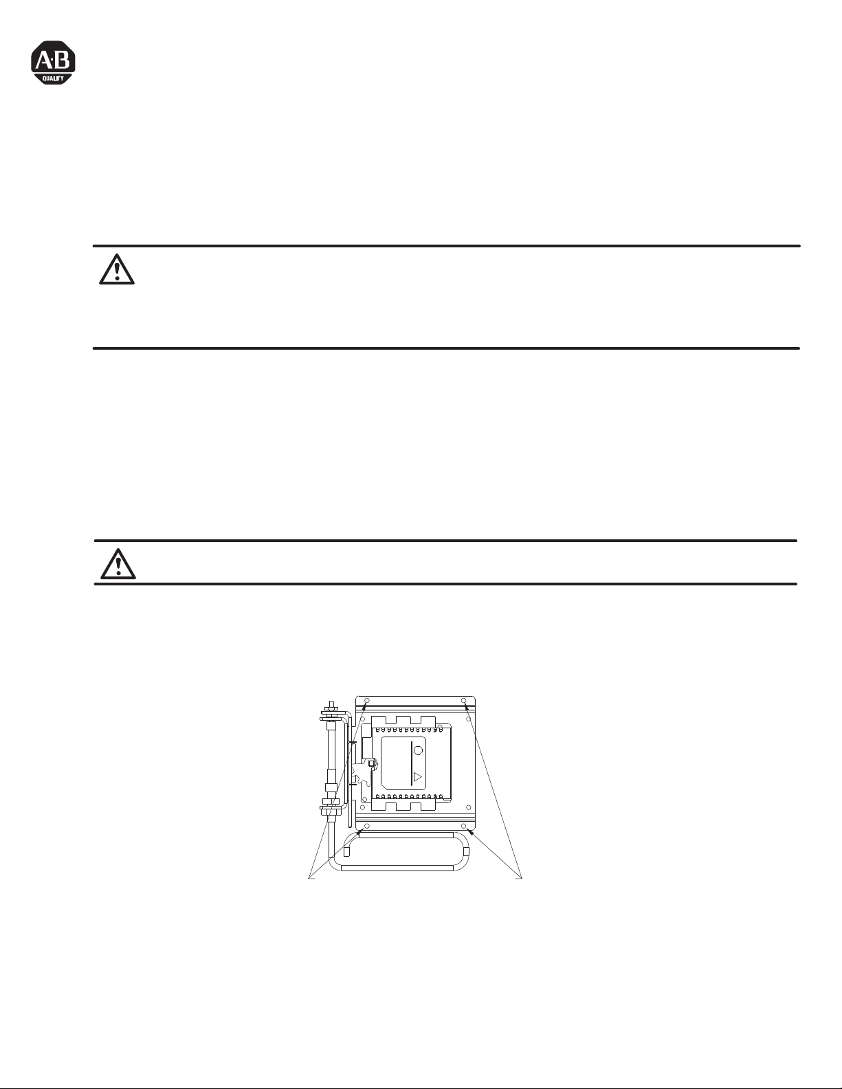
1. Install disconnect switch with four #10-32 screws. (See Figure 1-1).
Attach disconnect mechanism to enclosure back
panel using #10-32 screws through mounting holes
Figure 1-1 Attaching Disconnect to Enclosure Back Panel
Page 2
Bulletin 194RC Installation (Cont'd)
2. Install handle to enclosure by placing the outer handle mechanism with the attached gasket over the enclosure cutout. Insert
the top mounting screw with lockwasher through the enclosure and thread it into the outer handle mechanism for a few turns but
not all the way. (See Figure 1-2).
3. Slide the toggle mechanism assembly over the top handle mounting screw. Insert the bottom handle mounting screw and
lockwasher through the toggle mechanism assembly, through the enclosure and into the handle. Tighten both mounting screws
to specified torque. (See Figure 1-2).
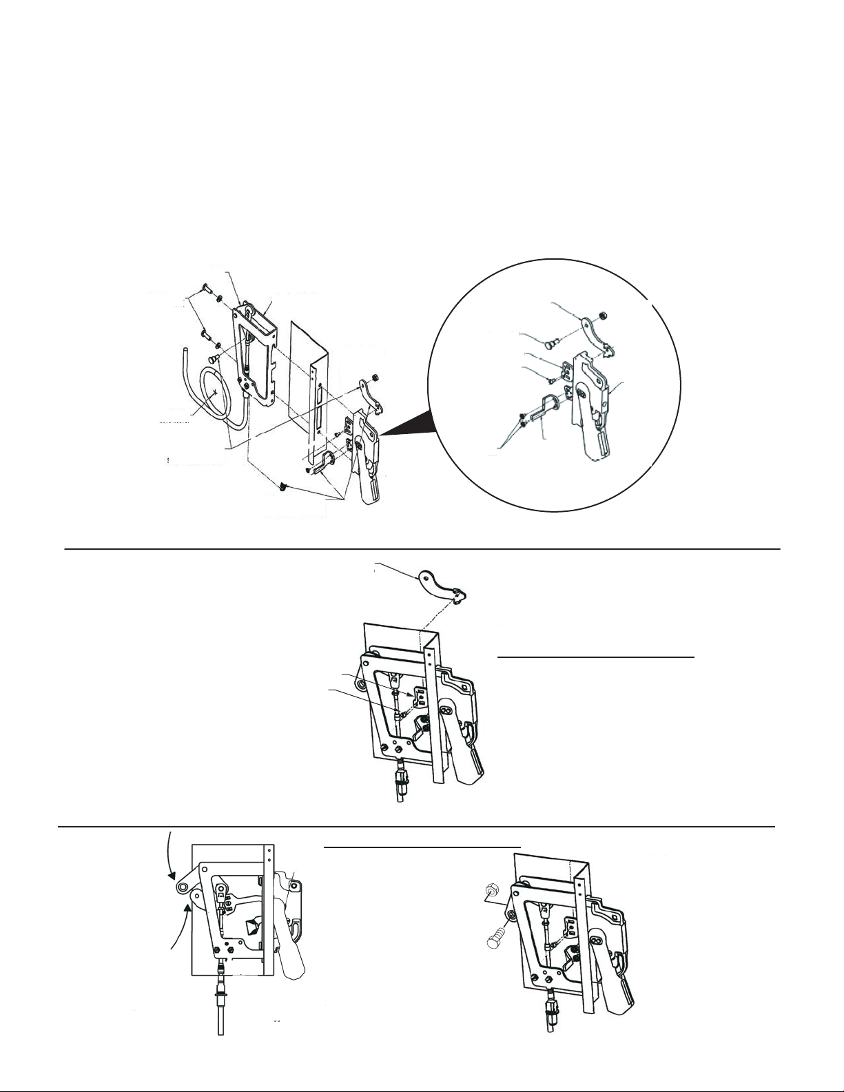
4. Assemble adapter link to actuator link. Tighten to specified torque. (See Figure 1-3).
5. Align adapter link with the bell crank. Attach bell crank to adapter link with shoulder bolt and nut. Tighten to specified torque.
(See Figure 1-4).
6. Mount door hasp to handle using the two screws provided with the handle. (See Figure 1-2).
7. Operate handle mechanism to ensure functionality. To operate either close door or defeat door interlock.
8. If minor adjustments are necessary, refer to adjustment checklist (Page 3).
9. Install appropriate door hardware (supplied). (See Figure 1-7).
Bail
23 - 37 lb-in
Max.
6" Min.
Bend Radius
Connect Adapter Link
to Bell Crank with
Shoulder Bolt and Nut
These items are to be assembled
after handle is mounted to enclosure
Toggle
Mechanism
7 - 11 lb-in
Adapter Link
Shoulder Bolt
18 - 20 lb-in
Actuator Link
18 - 20 lb-in
Max.
Door
Hasp
Figure 1-2 Securing Toggle Mechanism and Handle to Flange
Assemble Adaptor Link
with Screw to Actuator Link
Tighten to 18 - 20 lb-in.
Note: Make sure handle is in OFF position.
Actuator Link
Actuator Link Screw
Handle
Mechanism
Rotate Bell Crank
and Adaptor Link
to line up holes
Figure 1-3 Assembly of Adapter Link to Actuator Link
Note: Make sure handle is in OFF position.
After aligning assemble with
Shoulder Bolt and Nut
Tighten to 18 - 20 lb-in.
(2)
Figure 1-4 Assembly of Adapter Link to Bell Crank Using Shoulder Bolt
(2)
Page 3

ATTENTION: Before any installation or maintenance is performed, make sure that the disconnect switch is not energized.
Adjustment Checklist
Situation:
Handle and Cable Operated Mechanism turns ON, but disconnect switch does not transition to ON.
Adjustment:
Loosen the lifting washer
Check the OFF position of the actuator mechanism, that the lifting nut and sleeve of cable do not come into contact
with the bulkhead connector (Figure 1-5). If they do, move bulkhead connectors accordingly.
Situation:
Handle and Cable Operated Mechanism turns OFF, but disconnect switch does not transition to OFF.
Adjustment:
For the Cable Operated Disconnect Mechanism, loosen the washer
positive action. Tighten both nuts and recheck for ON and OFF positions (Figure 1-5).
Be certain after adjustment to have a minimum of 1 thread past the washer
If any other adjustment problems should arise, contact your local Allen-Bradley representative.
/
nut while tightening the washer / lockwasher / nut, two or three turns should be sufficient (see Figure
NOTICE
/
lock-washer / nut until the Disconnect Switch turns OFF with
NOTICE
/ l
ockwasher / nut assembly (Figure 1-5).
1-5).
Dimensions
Washer / Lockwasher / Nut
Tighten to 40 - 45 lb-in
Lifting Washer / Nut
Slider
Bulkhead Connector
Tighten to 65 - 70 lb-in
Figure 1-5 Cable Operated Disconnect Mechanism
6.891
4.300
ø .210
(3)
5.590
5.990
Page 4

Installation Instructions for Door Interlock
MIN.
2.75
INSIDE
2.25
DATUM
2 CLEARNACE HOLES
IN FLANGE FOR
1/4-20 SCREWS
.56 ±.01
3.44 ±.01
4.690 ±.005
.50 ±.01
"B" = .88
MOUNT HOOK IN UPPER HOLES
"B" = 1.56
MOUNT HOOK IN LOWER HOLES
UPPER HOLE
().25
()4.00
R.250
1.62
MIN.
.62
()B
1.5-2.0
MIN.5.75
()2.10
41053-274-01 (1)
Printed in U.S.A.
Figure 1-6 Flange Drilling Plan for Handle and Interlock Blade Mounting Dimensions
 Loading...