

Page 1
Installation Instructions
MicroLogix™ 1500 Programmable
Controller Base Units
(Catalog Numbers 1764-24AWA, 1764-24BWA, and
1764-28BXB)
http://literature.rockwellautomation.com/idc/groups/literature/documents/in/1
764-in001_-mu-p.pdf
FR
Cette publication est disponible en français sous forme électronique (fichier PDF). Pour la
télécharger, rendez-vous sur la page Internet indiquée ci-dessus.
IT
DE
ES
PT
Questa pubblicazione è disponibile in Italiano in formato PDF. Per scaricarla collegarsi al sito
Web indicato sopra.
Diese Publikation ist als PDF auf Deutsch verfügbar. Gehen Sie auf die oben genannte
Web-Adresse, um nach der Publikation zu suchen und sie herunterzuladen.
Esta publicación está disponible en español como PDF. Diríjase a la dirección web indicada
arriba para buscar y descarga esta publicación.
Esta publicação está disponível em portugués como PDF. Vá ao endereço web que aparece
acima para encontrar e fazer download da publicação.
Page 2

2 MicroLogix™ 1500 Programmable Controller Base Units
Publication 1764-IN001B-EN-P - March 2008
Page 3

Installation Instructions
MicroLogix™ 1500 Programmable
Controller Base Units
(Catalog Numbers 1764-24AWA, 1764-24BWA, and
1764-28BXB)
Inside...
For More Information.............................................................................. 4
Overview ................................................................................................. 5
Base Unit Description ............................................................................. 6
Hazardous Location Considerations ....................................................... 7
Mounting the Controller ......................................................................... 9
Wiring the Controller ............................................................................ 13
Specifications ....................................................................................... 17
Publication 1764-IN001B-EN-P
Page 4
4 MicroLogix™ 1500 Programmable Controller Base Units
For More Information
Table 1 Related Publications
For Refer to this Document Pub. No.
A more detailed description of how to
install and use your MicroLogix 1500
programmable controller.
A reference manual that contains data and
functin files, instruction set, and
troubleshooting information for
MicroLogix 1200 and MicroLogix 1500.
More information on proper wiring and
grounding techniques.
If you would like a manual, you can:
• download a free electronic version from the internet:
http://literature.rockwellautomation.com
• purchase a printed manual by contacting your local Allen-Bradley
distributor or Rockwell Automation representative
MicroLogix 1500
Programmable Controllers User
Manual
MicroLogix 1200 and
MicroLogix 1500 Instruction
Set Reference Manual
Industrial Automation Wiring
and Grounding Guidelines
1764-UM001A-US-P
1762-RM001B-US-P
1770-4.1
Publication 1764-IN001B-EN-P
Page 5
MicroLogix™ 1500 Programmable Controller Base Units 5
Overview
Install your controller using these installation instructions.
ATTENTION
!
ATTENTION
!
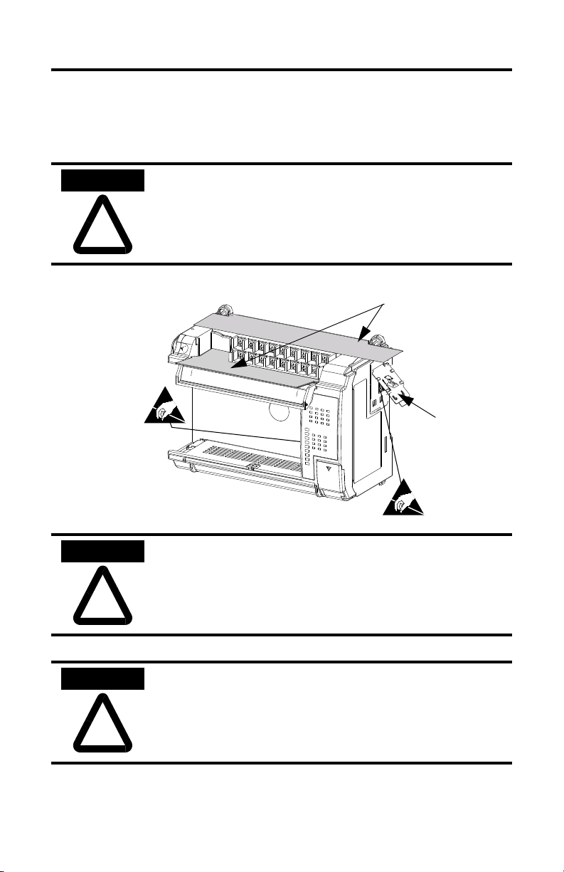
Do not remove protective debris strips until after the base and
all other equipment in the panel near the base is mounted and
wiring is complete. Once wiring is complete, remove
protective debris strips and install processor unit. Failure to
remove strips before operating can cause overheating.
Protective Debris
Strips
ESD Sticker
Be careful of metal chips when drilling mounting holes for
your controller or other equipment within the enclosure or
panel. Drilled fragments that fall into the controller could
cause damage. Do not drill holes above a mounted controller if
the protective debris strips have been removed.
ATTENTION
!
Electrostatic discharge can damage semiconductor devices
inside the base unit. Do not touch the connector pins or other
sensitive areas.
Publication 1764-IN001B-EN-P
Page 6
6 MicroLogix™ 1500 Programmable Controller Base Units
Base Unit Description
Table 2 Standard Base Units
Catalog Number Base Unit I/O and Power Supply
1764-24AWA 120V ac inputs/ relay outputs/ 120/240V ac power supply
1764-24BWA 24V dc inputs/ relay outputs/ 120/240V ac power supply
1764-28BXB 24V dc inputs/ FET and relay outputs/ 24V dc power supply
1
7
1
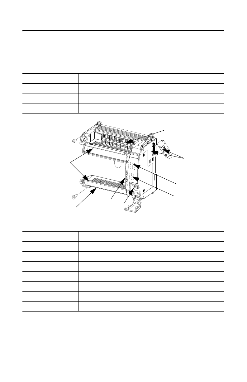
Table 3 Base Unit Description
Feature Description
1 Removable Terminal Blocks
2 Interface to Expansion I/O, Removable ESD Sticker
3 Input LEDs
4 Output LEDs
5 RS-232 Communication Port (CH0)
6 Status LEDs
7 Terminal Doors and Label
2
3
6
5
4
Publication 1764-IN001B-EN-P
Page 7
MicroLogix™ 1500 Programmable Controller Base Units 7
Hazardous Location Considerations
This equipment is suitable for use in Class I, Division 2, Groups A, B, C, D or
non-hazardous locations only. The following WARNING statement applies to
use in hazardous locations.
WARNING
!
Use only the following communication cables in Class I, Division 2 hazardous
locations.
Table 4 Cable Listing
Environment Classification Communication Cables
Class I, Division 2 Hazardous Environment 1761-CBL-PM02 Series C or later
EXPLOSION HAZARD
• Substitution of components may impair suitability for Class
I, Division 2.
• Do not replace components or disconnect equipment unless
power has been switched off or the area is known to be
non-hazardous.
• Do not connect or disconnect components unless power has
been switched off or the area is known to be non-hazardous.
• This product must be installed in an enclosure. All cables
connected to the product must remain in the enclosure or be
protected by conduit or other means.
• All wiring must comply with N.E.C. article 501-4(b).
1761-CBL-HM02 Series C or later
1761-CBL-AM00 Series C or later
1761-CBL-AP00 Series C or later
2707-NC8 Series B or later
2707-NC10 Series B or later
2707-NC11 Series B or later
Publication 1764-IN001B-EN-P
Page 8
8 MicroLogix™ 1500 Programmable Controller Base Units
Environnements dangereux
Cet équipement est conçu pour être utilisé dans des environnements de Classe 1,
Division 2, Groupes A, B, C, D ou non dangereux. La mise en garde suivante
s’applique à une utilisation dans des environnements dangereux.
MISE EN GARDE
!
DANGER D’EXPLOSION
• La substitution de composants peut rendre cet équipement impropre à
une utilisation en environnement de Classe 1, Division 2.
• Ne pas remplacer de composants ou déconnecter l'équipement sans
s'être assuré que l'alimentation est coupée et que l'environnement est
classé non dangereux.
• Ne pas connecter ou déconnecter des composants sans s'être assuré que
l'alimentation est coupée ou que l'environnement est classé non
dangereux.
• Ce produit doit être installé dans une armoire. Tous les câbles qui lui sont
connectés doivent rester dans l'armoire ou être protégés par un conduit
ou par d'autres moyens.
N'utilisez que les câbles de communication suivants dans des environnements
dangereux de Classe 1, Division 2.
Table 5 Liste des câbles
Classification d'environnement Câbles de communication
Environnement dangereux Classe 1,
Division 2
1761-CBL-PM02, série C ou ultérieure
1761-CBL-HM02, série C ou ultérieure
1761-CBL-AM00, série C ou ultérieure
1761-CBL-AP00, série C ou ultérieure
2707-NC8, série B ou ultérieure
2707-NC10, série B ou ultérieure
2707-NC11, série B ou ultérieure
Publication 1764-IN001B-EN-P
Page 9
MicroLogix™ 1500 Programmable Controller Base Units 9
Mounting the Controller
General Considerations
Most applications require installation in an industrial enclosure (Pollution Degree
2) to reduce the effects of electrical interference (Over Voltage Category II) and
environmental exposure. Locate your controller as far as possible from power
lines, load lines, and other sources of electrical noise such as hard-contact
switches, relays, and AC motor drives. For more information on proper
grounding guidelines, see the Industrial Automation Wiring and Grounding
Guidelines publication 1770-4.1.
ATTENTION
Vertical mounting is not recommended due to heat build-up
considerations.
!
ATTENTION
!
NOTE
Be careful of metal chips when drilling mounting holes for
your controller or other equipment within the enclosure or
panel. Drilled fragments that fall into the base or processor unit
could cause damage. Do not drill holes above a mounted
controller if the protective debris strips have been removed or
the processor has been installed.
Remove the ESD sticker to install expansion I/O modules. An
end cap terminator (catalog numbers 1769-ECR or -ECL) or
an extension cable (catalog numbers 1769-CRR1, -CRR3,
-CLL1, -CLL3, -CRL1, -CRL3) must be used at the end of the
group of I/O modules attached to the MicroLogix 1500
Controller. The end cap terminator is not provided with the
base unit. A maximum of eight I/O modules may be connected
to the base.
Publication 1764-IN001B-EN-P
Page 10

10 MicroLogix™ 1500 Programmable Controller Base Units
Mounting Dimensions
A
B
C
Table 6 Dimensions
Dimension 1764-24AWA 1764-24BWA 1764-28BXB
Height (A) 138 mm (5.43 in.)
Width (B) 168 mm (6.62 in.)
Depth (C) 87 mm (3.43 in.)
Controller Spacing
The base unit is designed to be mounted horizontally, with the Compact™
expansion I/O extending to the right of the base unit. Allow 50 mm (2 in.) of
space on all sides for adequate ventilation, as shown below.
Top
Side
Side
Publication 1764-IN001B-EN-P
Bottom
Page 11

MicroLogix™ 1500 Programmable Controller Base Units 11
Using a DIN Rail
The base unit and expansion I/O DIN rail latches lock in the open position so that
an entire system can be easily attached to or removed from the DIN rail. The
maximum extension of the latch is 15 mm (0.67 in.) in the open position. A
flat-blade screw driver is required for removal of the base unit. The base can be
mounted to EN50022-35x7.5 or EN50022-35x15 DIN rails. DIN rail mounting
dimensions are shown below.
B
A
C
Table 7 DIN Rail Mounting Dimensions
Dimension Height
A 138 mm (5.43 in.)
B 47.6 mm (1.875 in.)
C 47.6 mm (1.875 in) DIN latch closed
54.7 mm (2.16 in.) DIN latch open
To install your base unit on the DIN rail:
1. Mount your DIN rail. (Make sure that the placement of the base unit on the
DIN rail meets the recommended spacing requirements, see
“Controller
Spacing” on page 10. Refer to the mounting template from the inside back
cover of this document.)
2. Hook the top slot over the DIN rail.
3. While pressing the base unit down against the top of the rail, snap the bottom
of the base unit into position.
4. Leave the protective debris strip attached until you are finished wiring the base
unit and any other devices.
Publication 1764-IN001B-EN-P
Page 12

12 MicroLogix™ 1500 Programmable Controller Base Units
To remove your base unit from the DIN rail:
1. Place a flat-blade screwdriver in the DIN rail latch at the bottom of the base
unit.
2. Holding the base unit, pry downward on the latch until the latch locks in the
open position. This releases the base unit from the DIN rail.
Using Mounting Screws
Mount to panel using #8 or M4 screws.
Publication 1764-IN001B-EN-P
Mounting Template
Page 13

MicroLogix™ 1500 Programmable Controller Base Units 13
To install your base unit using mounting screws:
1. Remove the mounting template from the inside back cover of this document.
2. Secure the template to the mounting surface. (Make sure your base unit is
spaced properly, see
“Controller Spacing” on page 10).
3. Drill holes through the template.
4. Remove the mounting template.
5. Mount the base unit.
6. Leave the protective debris strips attached until you are finished wiring the
base unit and any other devices.
Wiring the Controller
Terminal Block Layout
1764-24BWA
1764-24AWA
1764-28BXB
85-265
VAC
85-265
VAC
24 VDC
NOT
USED
+24V
L1
L1
USED
L2
L2
NOT
COM
DC
POWER
OUT
VAC
VDC 0
VAC
VDC 0
DC
COM 0
I / 0
VAC
VDC 0
+24V
COM
VAC
VDC 1
NOT
USED
NOT
USED
VAC
VDC 1
O / 0
I / 1 I / 3
I / 2
VAC
VDC 1
DC
I / 1
I / 3
I / 4
COM 0
I / 2
I / 0
VAC
VDC 2
AC
COM 0
I / 0
VAC
VDC 2
O / 1
DC
COM 1
VDC 2 O / 5O / 3
COM 1
VAC
VDC 4
VDC 3
O / 3
I / 1
I / 3
I / 2
COM 1
VAC
VDC 4
VDC 3
O / 2 O / 6 O / 9 O / 11
O / 3
I / 4 I / 6
I / 5
O / 4
I / 6
DC
VAC
O / 4O / 1O / 0 O / 2 O / 6 O / 9 O / 11
I / 4
AC
VAC
O / 4
DC
COM 2
I / 7
O / 6O / 1O / 0 O / 2 O / 11
I / 7
I / 5
O / 5
O / 7 O / 8
I / 6
I / 7
I / 5
O / 5
O / 7 O / 8 O / 10
I / 9
I / 8 I / 10
VAC
O / 7
VDC 3
VDC
COM 2
COM 2
Publication 1764-IN001B-EN-P
DC
I / 8
VAC
VDC 5
AC
COM 2
I / 8
VAC
VDC 5
I / 12 I / 14
O / 9 O / 10
O / 8
I / 9
I / 9
I / 13I / 11
VAC
VDC 4
I / 10
O / 10
I / 10
I / 11
24BWA
24BWA
I / 11
24AWA
24AWA
I / 15
28BXB
28BXB
Page 14

14 MicroLogix™ 1500 Programmable Controller Base Units
Wire Requirements
Table 8 Wire Type Recommendation
Wire Type Wire Size (2 wire maximum per terminal
screw)
Solid Cu-90°C (194°F) #14 to #22 AWG
Stranded Cu-90°C (194°F) #14 to #22 AWG
Wiring torque = 1.13 Nm (10 in-lb) rated; 1.3 Nm (12 in-lb) maximum
ATTENTION
!
Be careful when stripping wires. Wire fragments that fall into
the controller could cause damage. Once wiring is complete,
be sure the base unit is free of all metal fragments before
removing protective debris strips and installing the processor
unit. Failure to remove strips before operating can cause
overheating.
Wiring Recommendation
When wiring without spade lugs, keep the finger-safe covers in place. Loosen the
terminal screw and route the wires through the opening in the finger-safe cover.
Tighten the terminal screw making sure the pressure plate secures the wire.
Finger-Safe Cover
Publication 1764-IN001B-EN-P
Page 15

MicroLogix™ 1500 Programmable Controller Base Units 15
Spade Lug Recommendation
The diameter of the terminal screw head is 5.5 mm (0.220 in.). The input and
output terminals of the MicroLogix 1500 base unit are designed for the following
spade lugs. The terminals will accept a 6.35mm (0.25 in.) wide spade (standard
for #6 screw for up to 14 AWG) or a 4 mm (metric #4) fork terminal.
When using spade lugs, use a small, flat-blade screwdriver to pry the finger-safe
cover from the terminal blocks, then loosen the terminal screw.
Finger-Safe Cover
Surge Suppression
ATTENTION
!
Inductive load devices such as motor starters and solenoids
require the use of some type of surge suppression to protect the
controller output. Switching inductive loads without surge
suppression can significantly reduce the lifetime of relay
contacts or damage transistor outputs. By using suppression,
you also reduce the effects of voltage transients caused by
interrupting the current to that inductive device, and prevent
electrical noise from radiating into system wiring.
Publication 1764-IN001B-EN-P
Page 16

16 MicroLogix™ 1500 Programmable Controller Base Units
Grounding the Controller
ATTENTION
!
In solid-state control systems, grounding and wire routing helps limit the effects
of noise due to electromagnetic interference (EMI). Run the ground connection
from the ground screw of the base unit to the ground bus prior to connecting any
devices. Use AWG #14 wire. This connection must be made for safety purposes.
You must also provide an acceptable grounding path for each device in your
application. For more information on proper grounding guidelines, see the
Industrial Automation Wiring and Grounding Guidelines publication 1770-4.1.
All devices connected to the RS-232 channel must be
referenced to base unit ground or floating. Failure to follow
this procedure may result in property damage or personal
injury.
Publication 1764-IN001B-EN-P
Page 17

MicroLogix™ 1500 Programmable Controller Base Units 17
Specifications
Table 9 General Specifications
Description 1764-24BWA 1764-24AWA 1764-28BXB
Number of I/O 12 inputs
12 outputs
Line Power 85/265V ac 85/265V ac 20.4 to 30V dc
Power Supply Inrush 120V ac = 25A
for 8 ms
240V ac = 40A
for 4 ms
User Power Output 24V dc at 400 mA,
400 µf max.
Input Circuit Type 24V dc, sink/source 120V ac 24V dc, sink/source
Output Circuit Type relay relay 6 relay,
Operating Temp. +0°C to +55°C (+32°F to +131°F) ambient
Storage Temp. -40°C to +85°C (-40°F to +185°F) ambient
Operating Humidity 5% to 95% relative humidity (non-condensing)
Vibration Operating: 10 to 500 Hz, 5G, 0.015 in. peak-to-peak
Relay Operation: 2G
Shock (without Data
Access Tool installed)
Shock (with Data Access
Tool installed)
Agency Certification •UL 508
Terminal Screw Torque 1.13 Nm (10 in-lb) rated; 1.3 Nm (12 in-lb) maximum
Power Supply Isolation 2596V dc 2596V dc 1697V dc
Relay Outputs Isolation 2596V dc 2596V dc 2596V dc
Transistor Output Isolation none none 1697V dc
Inputs Isolation 2145V dc 2145V dc 1697V dc
User 24V Isolation 848V dc none none
Operating: 30G panel mounted (15G DIN Rail mounted)
Relay Operation: 7.5G panel mounted (5G DIN Rail mounted)
Non-Operating: 40G panel mounted (30G DIN Rail mounted)
Operating: 20G panel mounted (15g DIN Rail mounted)
Relay Operation: 7.5G panel mounted (5G DIN Rail mounted)
Non-Operating: 30G panel mounted (20G DIN Rail mounted)
• C-UL under CSA C22.2 no. 142
• Class I, Div. 2, Groups A, B, C, D
(UL 1604, C-UL under CSA C22.2 no. 213)
• CE compliant for all applicable directives
12 inputs
12 outputs
120V ac = 25A
for 8 ms
240V ac = 40A
for 4 ms
none none
16 inputs
12 outputs
24V dc = 4A
for 150 ms
6 FET transistor
Publication 1764-IN001B-EN-P
Page 18

18 MicroLogix™ 1500 Programmable Controller Base Units
Table 10 Input Specifications
Description 1764-24AWA 1764-24BWA and 1764-28BXB
Inputs 0 thru 7 Inputs 8 and Higher
On State Voltage
Range
Off State Voltage
Range
Operating Frequency 47 Hz to 63 Hz 0 Hz to 20 KHz
On State Current:
•minimum
•nominal
• maximum
Off State Leakage
Current
Nominal Impedance 12k ohms at 50 Hz
Inrush Current (max.)
at 120V ac
(1) Scan-time dependant.
79 to 132V ac 14 to 30.0 V dc at 30°C
(86°F)
14 to 26.4 V dc at 55°C
(131°F)
10 to 30.0 V dc at 30°C
(86°F)
10 to 26.4 V dc at 55°C
(131°F)
0 to 20V ac 0 to 5V dc
0 Hz to 1 KHz
(1764-24BWA)
• 2.0 mA at 10V dc
• 8.9 mA at 24V dc
• 12.0 mA at 30V dc
• 5.0 mA at 79V ac
• 12.0 mA at 120V ac
• 16.0 mA at 132V ac
(1764-24BWA)
• 2.5 mA at 14V dc
• 7.3 mA at 24V dc
• 12.0 mA at 30V dc
2.5 mA minimum 1.5 mA minimum
3.3k ohms 2.7k ohms
10k ohms at 60 Hz
250 mA Not Applicable Not Applicable
(1)
Table 11 Output Specifications
Specification 1764-24AWA/BWA 1764-28BXB
Current per Common 8A 8A
Current per Controller at 150V Maximum 24A 18A
at 240V Maximum 20A 18A
Table 12 Relay Contact Rating Table 1764-24AWA, -24BWA, -28BXB
Maximum Volts Amperes Amperes
Make Break Make Break
Continuous
240V ac 7.5A 0.75A 2.5A 1800 VA 180 VA
120V ac 15A 1.5A
125V dc
24V dc
(1) For dc voltage applications, the make/break ampere rating for relay contacts can be determined by dividing
28 VA by the applied dc voltage. For example, 28 VA/48V dc = 0.58A. For dc voltage applications less than
48V, the make/break ratings for relay contacts cannot exceed 2A
0.22A
1.2A
(1)
(1)
1.0A 28 VA
2.0A 28 VA
Publication 1764-IN001B-EN-P
Voltamperes
Page 19

MicroLogix™ 1500 Programmable Controller Base Units 19
Table 13 1764-28BXB FET Output Specifications
Specification General Operation
(Outputs 2 thru 7)
High Speed Operation
(Outputs 2 and 3 Only)
User Supply Voltage minimum 20.4V dc 20.4V dc
maximum 26.4V dc 26.4V dc
On-State Voltage
Drop
at maximum load
current
at maximum surge
1V dc Not Applicable
2.5V dc Not Applicable
current
Current Rating per
Point
maximum load 1A at 55°C (131°F)
1.5A at 30°C (86°F)
100 mA
minimum load 1.0 mA 10 mA
maximum leakage 1.0 mA 1.0 mA
Surge Current per
Point
peak current 4.0A Not Applicable
maximum surge
10 msec Not Applicable
duration
maximum rate of
once every second Not Applicable
repetition at 30°C
(86°F)
maximum rate of
once every 2 seconds Not Applicable
repetition at 55°C
(131°F)
Current per Common maximum total 6A 6A
Turn-On Time maximum 0.1 msec 6 µsec
Turn-Off Time maximum 1.0 msec 18 µsec
Repeatability maximum n/a 2 µsec
Drift maximum n/a 1 µsec per 5°C
(1 µsec per 9°F)
(1) Outputs 2 and 3 are designed to provide increased functionality over the other FET outputs (4 through 7).
They may be used like the other FET transistor outputs, but in addition, within a limited current range, they
may be operated at a higher speed. Outputs 2 and 3 also provide a pulse train output (PTO) or pulse width
modulation output (PWM) function.
(1)
Publication 1764-IN001B-EN-P
Page 20

20 MicroLogix™ 1500 Programmable Controller Base Units
Table 14 Working Voltage
Specification 1764-L24AWA
Power Supply Input to Backplane
Isolation
Input Group to Backplane Isolation and
Input Group to Input Group Isolation
Output Group to Backplane Isolation Verified by one of the following dielectric tests: 1836V
Output Group to Output Group Isolation Verified by one of the following dielectric tests: 1836V
Specification 1764-24BWA
Power Supply Input to Backplane
Isolation
Power Supply User 24V Output to
Backplane Isolation
Input Group to Backplane Isolation and
Input Group to Input Group Isolation
Output Group to Backplane Isolation Verified by one of the following dielectric tests: 1836V
Output Group to Output Group Isolation. Verified by one of the following dielectric tests: 1836V
Verified by one of the following dielectric tests: 1836V
ac for 1 second or 2596V dc for 1 second
265V Working Voltage (IEC Class 2 reinforced
insulation)
Verified by one of the following dielectric tests: 151V
ac for 1 second or 2145V dc for 1 second
132V Working Voltage (IEC Class 2 reinforced
insulation)
ac for 1 second or 2596V dc for 1 second
265V Working Voltage (IEC Class 2 reinforced
insulation)
ac for 1 second or 2596V dc for 1 second
265V Working Voltage (basic insulation) 150V Working
Voltage (IEC Class 2 reinforced insulation).
Verified by one of the following dielectric tests: 1836V
ac for 1 second or 2596V dc for 1 second
265V Working Voltage (IEC Class 2 reinforced
insulation)
Verified by one of the following dielectric tests: 600V
ac for 1 second or 848V dc for 1 second
50V Working Voltage (IEC Class 2 reinforced
insulation)
Verified by one of the following dielectric tests: 1200V
ac for 1 second or 1697V dc for 1 second
75V dc Working Voltage (IEC Class 2 reinforced
insulation)
ac for 1 second or 2596V dc for 1 second
265V Working Voltage (IEC Class 2 reinforced
insulation).
ac for 1 second or 2596V dc for 1 second
265V Working Voltage (basic insulation) 150V Working
Voltage (IEC Class 2 reinforced insulation)
Publication 1764-IN001B-EN-P
Page 21

MicroLogix™ 1500 Programmable Controller Base Units 21
Table 14 Working Voltage
Specification 1764-28BXB
Input Group to Backplane Isolation and
Input Group to Input Group Isolation
FET Output Group to Backplane Isolation
and FET Outputs Group to Group
Relay Output Group to Backplane
Isolation
Relay Output Group to Relay and FET
Output Group Isolation
Verified by one of the following dielectric tests: 1200V
ac for 1 second or 1697V dc for 1 second
75V dc Working Voltage (IEC Class 2 reinforced
insulation)
Verified by one of the following dielectric tests: 1200V
ac for 1 second or 1697V dc for 1 second
75V dc Working Voltage (IEC Class 2 reinforced
insulation)
Verified by one of the following dielectric tests: 1836V
ac for 1 second or 2596V dc for 1 second
265V Working Voltage (IEC Class 2 reinforced
insulation)
Verified by one of the following dielectric tests: 1836V
ac for 1 second or 2596V dc for 1 second
265V Working Voltage (basic insulation) 150V Working
Voltage (IEC Class 2 reinforced insulation)
Publication 1764-IN001B-EN-P
Page 22

22 MicroLogix™ 1500 Programmable Controller Base Units
Notes:
Publication 1764-IN001B-EN-P
Page 23

Notes:
MicroLogix™ 1500 Programmable Controller Base Units 23
Publication 1764-IN001B-EN-P
Page 24

24 MicroLogix™ 1500 Programmable Controller Base Units
Notes:
Publication 1764-IN001B-EN-P
Page 25

Notes:
MicroLogix™ 1500 Programmable Controller Base Units 25
Publication 1764-IN001B-EN-P
Page 26

Mounting Template
132 mm
(5.19 in.)
122 mm
(4.813 in.)
DIN rail center line.
Ligne médiane du rail DIN.
Mittellinie der DIN-Schiene.
Línea central del riel DIN.
Linea centrale della guida DIN
linha de centro do trilho DIN.
168 mm
(6.62 in.)
Base Unit
Unité de base
Grundeinheiten
Unità di base
Unidad Base
Unidades Base
35 mm
(1.37 in.)
Expansion I/O
d'extension d'E/S
E/AErweiterungsmodule
l’espansione dei
moduli I/O
de expansión de E/S
de expansão de E/S
147 mm
(5.78 in.)
38 mm
(1.49 in.)
1764-IN001B-EN-P
Page 27

Rockwell Automation Support
Rockwell Automation provides technical information on the Web to assist you in using its
products. At http://support.rockwellautomation.com
knowledge base of FAQs, technical and application notes, sample code and links to software
service packs, and a MySupport feature that you can customize to make the best use of
these tools.
For an additional level of technical phone support for installation, configuration and
troubleshooting, we offer TechConnect support programs. For more information, contact your
local distributor or Rockwell Automation representative, or visit
http://support.rockwellautomation.com
.
Installation Assistance
If you experience a problem with a hardware module within the first 24 hours of installation,
please review the information that's contained in this manual. You can also contact a special
Customer Support number for initial help in getting your module up and running:
United States 1.440.646.3434 Monday – Friday, 8am – 5pm EST
Outside United States Please contact your local Rockwell Automation representative for any technical
support issues.
New Product Satisfaction Return
Rockwell Automation tests all of its products to ensure that they are fully operational when
shipped from the manufacturing facility. However, if your product is not functioning and
needs to be returned, follow these procedures.
United States Contact your distributor. You must provide a Customer Support case number (see
Outside United States Please contact your local Rockwell Automation representative for return procedure.
Allen-Bradley, Rockwell Automation, MicroLogix, and TechConnect are trademarks of Rockwell Automation, Inc.
Trademarks not belonging to Rockwell Automation are property of their respective companies.
phone number above to obtain one) to your distributor in order to complete the return
process.
, you can find technical manuals, a
Publication 1764-IN001B-EN-P - March 2008 PN 40072-089-01(C)
Supersedes Publication 1764-IN001A-EN-P - September 2007 Copyright © 2008 Rockwell Automation, Inc. All rights reserved. Printed in Singapore.
 Loading...