

Page 1

User Manual
MicroLogix 1100 Embedded Web Server
Bulletin 1763 Controllers
Page 2
Important User Information
IMPORTANT
Solid-state equipment has operational characteristics differing from those of electromechanical equipment. Safety
Guidelines for the Application, Installation and Maintenance of Solid State Controls (publication SGI-1.1
your local Rockwell Automation sales office or online at http://www.rockwellautomation.com/literature/
important differences between solid-state equipment and hard-wired electromechanical devices. Because of this difference,
and also because of the wide variety of uses for solid-state equipment, all persons responsible for applying this equipment
must satisfy themselves that each intended application of this equipment is acceptable.
In no event will Rockwell Automation, Inc. be responsible or liable for indirect or consequential damages resulting from
the use or application of this equipment.
The examples and diagrams in this manual are included solely for illustrative purposes. Because of the many variables and
requirements associated with any particular installation, Rockwell Automation, Inc. cannot assume responsibility or
liability for actual use based on the examples and diagrams.
No patent liability is assumed by Rockwell Automation, Inc. with respect to use of information, circuits, equipment, or
software described in this manual.
Reproduction of the contents of this manual, in whole or in part, without written permission of Rockwell Automation,
Inc., is prohibited.
Throughout this manual, when necessary, we use notes to make you aware of safety considerations.
WARNING: Identifies information about practices or circumstances that can cause an explosion in a hazardous
environment, which may lead to personal injury or death, property damage, or economic loss.
available from
) describes some
ATTENTION: Identifies information about practices or circumstances that can lead to personal injury or death,
property damage, or economic loss. Attentions help you identify a hazard, avoid a hazard, and recognize the
consequence
SHOCK HAZARD: Labels may be on or inside the equipment, for example, a drive or motor, to alert people that
dangerous voltage may be present.
BURN HAZARD: Labels may be on or inside the equipment, for example, a drive or motor, to alert people that
surfaces may reach dangerous temperatures.
Identifies information that is critical for successful application and understanding of the product.
Allen-Bradley, Rockwell Software, Rockwell Automation, SLC 5/02, SLC 5/03, PLC-5, MicroLogix, SLC 500, RSLogix 500, RSLinx, and TechConnect are trademarks of Rockwell Automation, Inc.
Trademarks not belonging to Rockwell Automation are property of their respective companies.
Page 3

Summary of Changes
The information below summarizes the changes to this manual since the last
printing.
To help you find new and updated information in this release of the manual, we
have included change bars as shown next to this paragraph.
The table below lists the sections that document new features and additional or
updated information about existing features. Web view disable function is added.
Top ic
Disable Web View
Browser support is specified as Internet Explorer 6.0 , 7.0, and 8.0.
Internet Explorer 9.0 and above are not supported.
Page
9
1
Rockwell Automation Publication 1763-UM002D-EN-P - May 2014 iii
Page 4

Chapter 1
Notes:
iv Rockwell Automation Publication 1763-UM002D-EN-P - May 2014
Page 5

Chapter 1
Table of Contents
MicroLogix 1100 Embedded
Web Server
Use Data Views to Access
Controller Data
Manage User Accounts and
Access Levels
How to Use This Chapter . . . . . . . . . . . . . . . . . . . . . . . . . . . . . . . . . . . . . . . . . . 1
Typical Applications . . . . . . . . . . . . . . . . . . . . . . . . . . . . . . . . . . . . . . . . . . . . . . . 1
Browser Requirements. . . . . . . . . . . . . . . . . . . . . . . . . . . . . . . . . . . . . . . . . . . . . . 1
Connect the MicroLogix 1100 controller to the Network . . . . . . . . . . . . . 2
1. Connect the module to the network . . . . . . . . . . . . . . . . . . . . . . . . . . . 2
2. Obtain an IP address. . . . . . . . . . . . . . . . . . . . . . . . . . . . . . . . . . . . . . . . . 2
3. Access the home page of the web server. . . . . . . . . . . . . . . . . . . . . . . . . 3
4. Log into the web server.. . . . . . . . . . . . . . . . . . . . . . . . . . . . . . . . . . . . . . . 3
Navigate the MicroLogix 1100 Controller. . . . . . . . . . . . . . . . . . . . . . . . . . . . 4
Chapter 2
How to Use This Chapter . . . . . . . . . . . . . . . . . . . . . . . . . . . . . . . . . . . . . . . . . . 5
Overview of Data Views . . . . . . . . . . . . . . . . . . . . . . . . . . . . . . . . . . . . . . . . . . . . 5
Change an Access Group . . . . . . . . . . . . . . . . . . . . . . . . . . . . . . . . . . . . . . . . . . . 6
Data View Page . . . . . . . . . . . . . . . . . . . . . . . . . . . . . . . . . . . . . . . . . . . . . . . . 7
Change Data Table Files . . . . . . . . . . . . . . . . . . . . . . . . . . . . . . . . . . . . . . . . . . . . 7
How to Change a Data File Type . . . . . . . . . . . . . . . . . . . . . . . . . . . . . . . . 8
Disable Web View. . . . . . . . . . . . . . . . . . . . . . . . . . . . . . . . . . . . . . . . . . . . . . . . . . 9
Chapter 3
How to Use This Chapter . . . . . . . . . . . . . . . . . . . . . . . . . . . . . . . . . . . . . . . . 11
User Accounts and Privilege Classes . . . . . . . . . . . . . . . . . . . . . . . . . . . . . . . 11
Configure Access Limits for Web Pages . . . . . . . . . . . . . . . . . . . . . . . . . . . . 12
Recover with Unknown Password . . . . . . . . . . . . . . . . . . . . . . . . . . . . . . . . . 14
Chapter 4
Monitor Diagnostics
How to Use This Chapter . . . . . . . . . . . . . . . . . . . . . . . . . . . . . . . . . . . . . . . . 15
MicroLogix 1100 Controller Diagnostics. . . . . . . . . . . . . . . . . . . . . . . . . . . 15
Network Status . . . . . . . . . . . . . . . . . . . . . . . . . . . . . . . . . . . . . . . . . . . . . . . . . . 18
Index
Rockwell Automation Publication 1763-UM002D-EN-P - May 2014 v
Page 6

Table of Contents
Notes:
vi Rockwell Automation Publication 1763-UM002D-EN-P - May 2014
Page 7

Chapter
MicroLogix 1100 Embedded Web Server
1
How to Use This Chapter
Typical Applications
Browser Requirements
Rockwell Automation offers enhanced MicroLogix 1100 controllers for your
EtherNet/IP control systems so you can monitor data remotely via web pages.
This chapter shows how you can use a MicroLogix 1100 controller in your
control system.
Top ic
Typical Applications
Browser Requirements
Connect the MicroLogix 1100 controller to the Network
Navigate the MicroLogix 1100 Controller
The MicroLogix 1100 controller provides access to controller data. This access
opens up different, remote access applications to control systems. Use the
MicroLogix 1100 controller to remotely access controller data using a web
browser. Use a web browser to monitor live controller data.
You can access the MicroLogix 1100 Web Server only with Internet Explorer 6, 7,
or 8. Internet Explorer 9 or above are not supported because of JavaScript
incompatibility.
Page
1
1
2
4
To access data view pages, the browser requires Javascript support.
The supported display size is 640 x 480 or greater. Smaller display sizes work but
might require extensive scrolling to view the information.
Rockwell Automation Publication 1763-UM002D-EN-P - May 2014 1
Page 8
Chapter 1 MicroLogix 1100 Embedded Web Server
IMPORTANT
Connect the MicroLogix 1100 controller to the Network
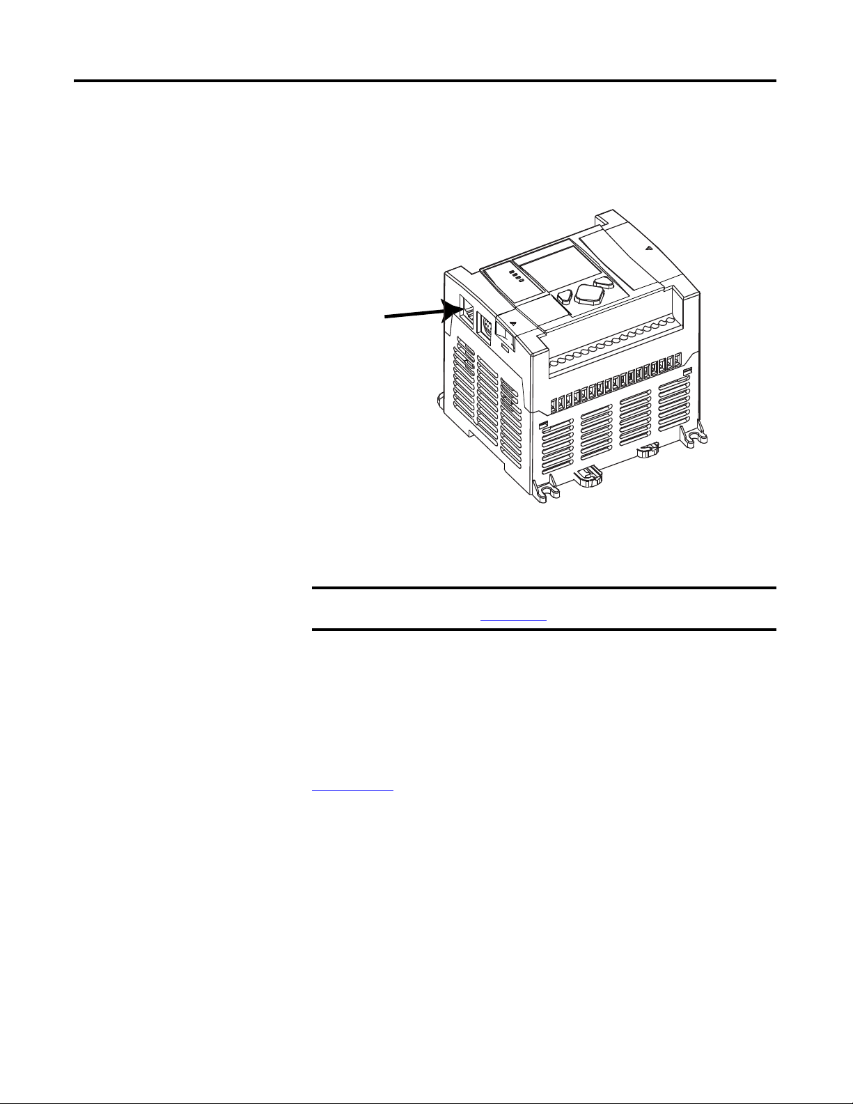
1. Connect the module to the network
Connect the MicroLogix 1100 controller to the Ethernet network. The RJ-45
connector is on the left-hand side of the module.
2. Obtain an IP address.
For more information, see MicroLogix1100 Programmable Controllers
User Manual, 1763-UM001
By default, the MicroLogix 1100 controller is BOOTP enabled. If you connect
the MicroLogix 1100 controller to a network that has a BOOTP server, that
server will assign an IP address to the MicroLogix 1100 controller and the LCD
screen of the MicroLogix 1100 controller will display BOOTP IP address.
If your network does not have a BOOTP server, use one of the methods
described in the MicroLogix 1100 Programmable Controllers User Manual
1763-UM001
to assign an IP address to the MicroLogix 1100 controller.
.
2 Rockwell Automation Publication 1763-UM002D-EN-P - May 2014
Page 9
MicroLogix 1100 Embedded Web Server Chapter 1
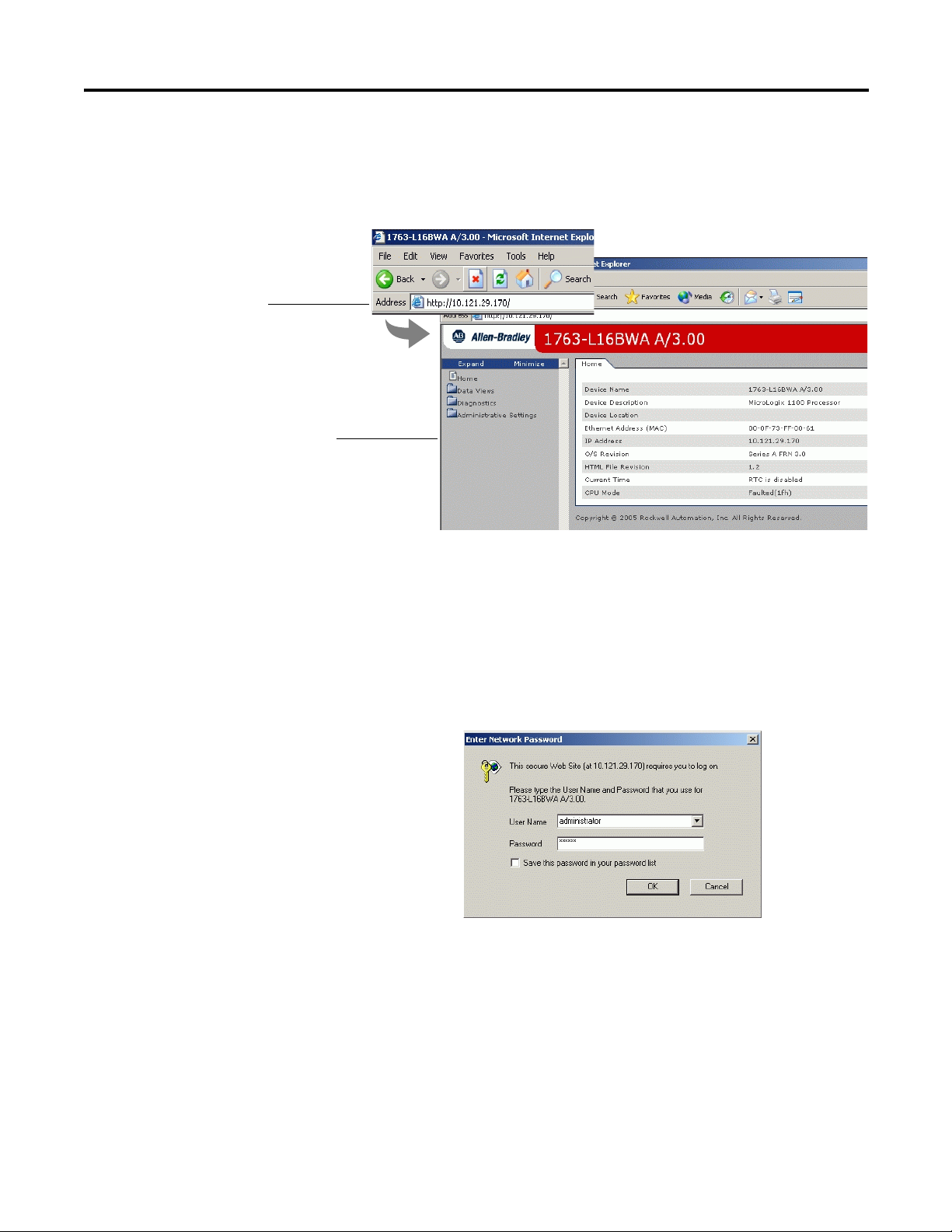
Specify the IP address of the
MicroLogix 1100 controller in the
Address window of your web
browser.
This is the module’s Home page.
Default Access
User Name: administrator or guest
(case sensitive)
Password:
(ml1100 for administrator, guest for guest)
3. Access the home page of the web server.
From your web browser, enter the IP address of the MicroLogix 1100 controller.
The module displays its Home page
4. Log into the web server.
Many of the features of the MicroLogix 1100 controller require you to log in with
appropriate access. If you select a feature, such as Data Views, the MicroLogix
1100 controller prompts you to enter your user name and password. The user
name is either administrator or guest. The password is ml1100 for administrator
and guest for guest.
You can set up as many as 10 user accounts. Each account can have read, write, or
administrator access. For more information, see Chapter 3.
Rockwell Automation Publication 1763-UM002D-EN-P - May 2014 3
Page 10

Chapter 1 MicroLogix 1100 Embedded Web Server
Click folders to open and close
additional levels of information.
Click a document to display a
web page showing specific
information.
Tabs across the top match the documents
within a folder, as shown in the left
navigation panel.
Navigate the MicroLogix 1100 Controller
You navigate the web server’s web pages by using the navigation panel on the left
of the screen. There are also tabs across the top you can use to navigate the
sections within folders.
4 Rockwell Automation Publication 1763-UM002D-EN-P - May 2014
Page 11

Chapter
2
Use Data Views to Access Controller Data
How to Use This Chapter
Overview of Data Views
The MicroLogix 1100 controllers provide access to the controller data table files.
This chapter shows you how to set up data views of data table files.
Top ic
Overview of Data Views
Change an Access Group
Monitor Data Views and Data Table File
Change Data Table Files
Disable Web View
Data views give you the ability to read from controller through a browser
interface. The MicroLogix 1100 controller provides web pages that let you
configure a set of files (a data view) that can be read.
A data view consists of an HTML file with data file information. The HTML file
is in a readable ASCII format. It contains the File Name, File Type, # of Element,
and Access Group.
Page
5
6
7
7
9
Rockwell Automation Publication 1763-UM002D-EN-P - May 2014 5
Page 12

Chapter 2 Use Data Views to Access Controller Data
Change an Access Group
Each data view contains a group of files that you want to monitor. Each
MicroLogix 1100 controller can support multiple data views. One browser
supports one data view, so if you want to look at many data views, you need to run
a corresponding number of browsers.
You change an access group from the Data Views → New Data View page.
1. From the Access Group pull-down menu for the given data table file,
choose the access group type you wish to assign. Choose from:
• Administrator (all access)
• Write (read/write access only)
• Read (read access only)
2. Choose Administrator, Write, or Read from the Access Group pull-down
menu to change a file's access group.
3. Click Apply to change an access group for the data table file you
specified.
6 Rockwell Automation Publication 1763-UM002D-EN-P - May 2014
Page 13

Use Data Views to Access Controller Data Chapter 2
Monitor Data Views and Data Table File
Use the Data Views → Data Views page to view existing data table files.
Click the file name to view the data within a data table file.
Data View Page
The Data Views page displays a list of the data table files, their type, and size in
elements for a connected MicroLogix 1100, as shown in the following example.
Change Data Table Files
Each file contains a hyperlink that takes you to the specific Data Views page for
that file. When you click a particular file, the Data Views page appears, displaying
the contents of the data table file you selected.
The available and default display formats depend on the data type of the file.
Click Back to display the previous page. To refresh data, click Update.
The data in the Data File Types such as Binary, Integer, Long, Float, and String
can be changed. The Binary, Integer, and Long types support all the Display
formats. The Binary can be changed by bit, and the octal, decimal, and
hexadecimal can be changed by element. A user account with either Write or
Rockwell Automation Publication 1763-UM002D-EN-P - May 2014 7
Page 14

Chapter 2 Use Data Views to Access Controller Data
Administrator access level can change the Data Table Files. When you click N7 in
Data Views, Data Writable appears beside a Data File Type (Integer here) as
shown below.
How to Change a Data File Type
The following steps assume Binary type is used.
1. Change Display As to Binary, then the following screen appears.
2. Double-click the data you want to change, then the background color
becomes pink.
8 Rockwell Automation Publication 1763-UM002D-EN-P - May 2014
Page 15

Use Data Views to Access Controller Data Chapter 2
3. Enter a value and either press Enter or click somewhere in the screen, then
a confirmation window appears.
4. Click OK to change the value in the server.
If following screen appears when the value is successfully saved into
the server.
Disable Web View
If the following screen appears, the value is not saved and the value returns
to the original value.
If you want to change the data in Decimal, click pull-down menu to change the
Display As to Decimal and follow the above procedures in sequence. The
procedures are all the same for String too. (This feature is supported only when
the OS FRN is 3 (HTML File Revision is 1.2) or later.
Using RSLogix 500 version 7.20 or higher, you can disable individual data files
from being viewed via any web browser by selecting the data file’s properties page
Rockwell Automation Publication 1763-UM002D-EN-P - May 2014 9
Page 16

Chapter 2 Use Data Views to Access Controller Data
and checking the Web View Disable checkbox as shown below. Any data file
property changes must be made offline and downloaded to the processor.
10 Rockwell Automation Publication 1763-UM002D-EN-P - May 2014
Page 17

Chapter
IMPORTANT
IMPORTANT
3
Manage User Accounts and Access Levels
How to Use This Chapter
This chapter describes how to configure user access levels to different information
on the module.
Top ic
User Accounts and Privilege Classes
Configure Access Limits for Web Pages
Create User Accounts
Recover with Unknown Password
By assigning user accounts with different access levels, you can manage which
users have access to view network configuration or have access to view and change
data views.
Several pages on the MicroLogix 1100 controller, such as diagnostics pages and
data views pages, have default access protection. Before accessing these pages, you
must authenticate your access by entering a user name and password. The module
displays the log-in box when you access these web pages.
Once authenticated, you do not have to re-enter a user name or
password when accessing subsequent pages. You must close
your browser to log out.
Page
11
12
13
14
The default user name is administrator with password 'ml1100' or guest with
password 'guest'
User Accounts and
Privilege Classes
Rockwell Automation Publication 1763-UM002D-EN-P - May 2014 11
The MicroLogix 1100 controller supports multiple user accounts, each with a
user name and password. Each user account is configured for one of these access
levels:
• Administrator (all access)
• Write (read/write access only)
• Read (read access only)
The access level determines which web pages the user can access. You configure
access limits for individual web pages.
.
It is strongly recommended that you change the password for
the default Administrator account.
Page 18

Chapter 3 Manage User Accounts and Access Levels
Configure Access Limits for
Each page in the MicroLogix 1100 controller has one of these protection levels:
Web Pages
The protection levels are hierarchical. Administrator users can access Read
protected pages.
These predefined pages (those web pages that come with the MicroLogix 1100
controller) in the MicroLogix 1100 controller have these default access levels. You
can change the Data View access group, if needed, with administrator privilege.
• Administrator
• Wr i t e
• Read
Web Page Default Protection Level
Home page no protection
Diagnostics pages Read protection
Data Views Read protection
New Data View Administrator protection
User Management page Administrator protection
12 Rockwell Automation Publication 1763-UM002D-EN-P - May 2014
Page 19

Manage User Accounts and Access Levels Chapter 3
IMPORTANT
Create User Accounts
You need Administrator access to create and modify user accounts. You can create
as many as 10 individual accounts. You manage accounts from the Administrative
Settings → User Manag ement → Edit Users page.
In this field Do this
User ID Enter the user name for the account.
20 characters maximum
Can contain these characters: A…Z, a…z, 0…9, underscore (_), and
dash (-)
Group Select Administrator, Write, or Read access for the user account
Password Enter the password for the account.
10 characters maximum
Confirm Password Re-enter the same password for the account.
If you use Internet Explorer, the number of characters allowed
for a user ID or password depends on how many characters “fit
in the box.” Larger characters (such as “W”) take more room
and reduce the total number of allowed characters.
A user account with a specific privilege can access the Data corresponding to the
specific access level, that is, a user account with Read access level can not access
the Data belonging to Write or Administrator acess group. The following screen,
which shows only Read Access Group, appears when you log in with the guest
account.
Rockwell Automation Publication 1763-UM002D-EN-P - May 2014 13
Page 20

Chapter 3 Manage User Accounts and Access Levels
Recover with Unknown Password
Update the firmware using ControlFlash to initialize both user accounts and the
access level of data view. This feature is supported only when the OS FRN is 3
(HTML File Revision is 1.2) or later.
14 Rockwell Automation Publication 1763-UM002D-EN-P - May 2014
Page 21

Monitor Diagnostics
Chapter
4
How to Use This Chapter
MicroLogix 1100 Controller Diagnostics
This chapter describes the diagnostics presented on the user-oriented diagnostic
pages.
Top ic
MicroLogix 1100 Controller Diagnostics
Diagnostic Overview
Network Settings
Network Status
The MicroLogix 1100 controller provides four diagnostic pages of user-oriented
diagnostics. This information is organized into:
For this information Access this web page
Overview of the current configuration of the
MicroLogix 1100 controller
Summary of the network settings configured for
the MicroLogix 1100 controller
Ethernet statistics Diagnostics
Diagnostics → Diagnostic Overview
Diagnostics → Network Settings
→ Ethernet Statistics
Page
15
16
17
18
Rockwell Automation Publication 1763-UM002D-EN-P - May 2014 15
Page 22

Chapter 4 Monitor Diagnostics
Diagnostic Overview
The Diagnostics → Diagnostic Overview page presents a summary of the current
configuration and overall status of the MicroLogix 1100 controller. This
summary includes:
• Ethernet configuration.
• Ethernet connection use.
This field Specifies
Ethernet Link
Port Speed whether the Ethernet port is operating @ 10 Mbps or 100 Mbps
Port Duplex whether the Ethernet port is operating @ half duplex or full duplex
Auto negotiate Status whether the port speed and duplex mode were determined via autonegotiation or whether they
Ethernet Connections
Current Ethernet Connections current number of active connections
Incoming Ethernet Connections current number of incoming connections
Outgoing Ethernet Connections current number of outgoing ethernet connections
Ethernet Connection Limit maximum number of Ethernet incoming/outgoing connections
were manually configured
16 Rockwell Automation Publication 1763-UM002D-EN-P - May 2014
Page 23

Monitor Diagnostics Chapter 4
Network Settings
The Diagnostics → Network Settings page presents a summary of the current
Ethernet configuration for MicroLogix 1100. This summary includes:
• Ethernet address details.
Any fields not configured remain blank.
This field Specifies
Network Interface
Ethernet Address (MAC) Ethernet (MAC) address of the controller
IP Address IP address for the controller
Subnet Mask subnet mask for the controller
Default Gateway gateway address for the controller
Rockwell Automation Publication 1763-UM002D-EN-P - May 2014 17
Page 24

Chapter 4 Monitor Diagnostics
Network Status
The Diagnostics → Network Status page presents a summary of the status of
communication activity on the Ethernet network. This summary includes:
• Ethernet network configuration.
• packets sent and received over the Ethernet network.
• frames sent and received over the Ethernet network.
This field Specifies
Interface Counters
Rx Octets Octets received on the Ethernet interface
Tx Octets Octets sent on the Ethernet interface
Rx Packets Packets received on the Ethernet interface
Tx Packets Packets sent on the Ethernet interface
Command Sent Command sent on the Ethernet interface
Command Received Command received on the Ethernet interface
Replies Sent Replies sent on the Ethernet interface
Replies Received Replies received on the Ethernet interface
Replies Sent with error Outbound packets that contain errors
Replies Received with error Inbound packets that contain errors
Replies Timed Out No reply within a specified time period
Media Counters
Single Collisions Successfully transmitted frames which experienced exactly one collision
Multiple Collisions Successfully transmitted frames which experienced more than one collision
Deferred Transmissions Frames for which first transmission attempt is delayed because the medium is busy
Late Collisions Number of times a collision is detected later than 512 bit-times into the transmission of a packet
Excessive Collisions Frames for which transmission fails due to excessive collisions
MAC Transmit Errors Frames for which transmission fails due to an internal MAC sublayer transmit error
18 Rockwell Automation Publication 1763-UM002D-EN-P - May 2014
Page 25

Monitor Diagnostics Chapter 4
This field Specifies
Carrier Sense Errors Times that the carrier sense condition was lost or never asserted when attempting to transmit
MAC Receive Errors Frames for which reception on the Ethernet interface failed due to an internal MAC sublayer
CRC Errors Frames for which CRC error is detected
a frame
receive error
Rockwell Automation Publication 1763-UM002D-EN-P - May 2014 19
Page 26

Chapter 4 Monitor Diagnostics
Notes:
20 Rockwell Automation Publication 1763-UM002D-EN-P - May 2014
Page 27

Index
A
access group
creating
access levels
classes
access limits
configuring
accessing
typical application
Administrator access 3-16
authentication 3-15
2-8
3-15
3-16
1-3
B
browser requirements 1-3
C
configuring
access limits
user accounts 3-17
connecting 1-4
creating
access group
3-16
2-8
network settings 4-21
I
installing 1-4
IP address 1-4
M
MicroLogix 1100 Controller Diagnostics 4-19
N
navigating 1-6
P
password 3-15, 3-18
R
Read access 3-16
recovering 3-18
remote access 1-3
requirements, browser 1-3
D
data views
monitoring
overview 2-7
Diagnostic Overview 4-20
diagnostics
diagnostic overview
Ethernet statistics 4-22
2-9
4-20
U
user accounts
3-15
classes
creating 3-17
W
write access 1-5
Rockwell Automation Publication 1763-UM002D-EN-P - May 2014
Page 28

22
Notes:
Publication 1763-UM002D-EN-P - May 2014
Page 29

Rockwell Automation Publication 1763-UM002D-EN-P - May 2014 23
Page 30

Rockwell Otomasyon Ticaret A.Ş., Kar Plaza İş Merkezi E Blok Kat:6 34752 İçerenköy, İstanbul, Tel: +90 (216) 5698400
Rockwell Automation Support
Rockwell Automation provides technical information on the Web to assist you in using its products.
At http://www.rockwellautomation.com/support/
application notes, sample code and links to software service packs, and a MySupport feature that you can customize to make the
best use of these tools.
For an additional level of technical phone support for installation, configuration, and troubleshooting, we offer TechConnect
support programs. For more information, contact your local distributor or Rockwell Automation representative,
or visit http://www.rockwellautomation.com/support/
Installation Assistance
If you experience a problem within the first 24 hours of installation, review the information that is contained in this manual.
You can contact Customer Support for initial help in getting your product up and running.
United States or Canada 1.440.646.3434
Outside United States or
Canada
Use the Worldwide Locator
your local Rockwell Automation representative.
, you can find technical manuals, a knowledge base of FAQs, technical and
.
at http://www.rockwellautomation.com/support/americas/phone_en.html, or contact
New Product Satisfaction Return
Rockwell Automation tests all of its products to ensure that they are fully operational when shipped from the manufacturing facility.
However, if your product is not functioning and needs to be returned, follow these procedures.
United States Contact your distributor. You must provide a Customer Support case number (call the phone number above to obtain
Outside United States Please contact your local Rockwell Automation representative for the return procedure.
one) to your distributor to complete the return process.
Documentation Feedback
Your comments will help us serve your documentation needs better. If you have any suggestions on how to improve this document,
complete this form, publication RA-DU002
, available at http://www.rockwellautomation.com/literature/.
Publication 1763-UM002D-EN-P - May 2014 24
Supersedes Publication 1763-UM002C-EN-P - April 2007 Copyright © 2014 Rockwell Automation, In c. All rights reserved. Printed in the U.S.A.
 Loading...