

Page 1

Pico DeviceNet Communication Interface
1760-DNET
User Manual
Page 2
Important User Information
Solid state equipment has operational characteristics differing from those of
electromechanical equipment. Safety Guidelines for the Application,
Installation and Maintenance of Solid State Controls (publication SGI-1.1
available from your local Rockwell Automation sales office or online at
http://www.rockwellautomation.com/literature) describes some important
differences between solid state equipment and hard-wired electromechanical
devices. Because of this difference, and also because of the wide variety of
uses for solid state equipment, all persons responsible for applying this
equipment must satisfy themselves that each intended application of this
equipment is acceptable.
In no event will Rockwell Automation, Inc. be responsible or liable for
indirect or consequential damages resulting from the use or application of
this equipment.
The examples and diagrams in this manual are included solely for illustrative
purposes. Because of the many variables and requirements associated with
any particular installation, Rockwell Automation, Inc. cannot assume
responsibility or liability for actual use based on the examples and diagrams.
No patent liability is assumed by Rockwell Automation, Inc. with respect to
use of information, circuits, equipment, or software described in this manual.
Reproduction of the contents of this manual, in whole or in part, without
written permission of Rockwell Automation, Inc. is prohibited.
Throughout this manual, when necessary we use notes to make you aware of
safety considerations.
WARNING
IMPORTANT
ATTENTION
SHOCK HAZARD
BURN HAZARD
Identifies information about practices or circumstances
that can cause an explosion in a hazardous environment,
which may lead to personal injury or death, property
damage, or economic loss.
Identifies information that is critical for successful
application and understanding of the product.
Identifies information about practices or circumstances
that can lead to personal injury or death, property
damage, or economic loss. Attentions help you:
• identify a hazard
• avoid a hazard
• recognize the consequence
Labels may be located on or inside the equipment (e.g.,
drive or motor) to alert people that dangerous voltage may
be present.
Labels may be located on or inside the equipment (e.g.,
drive or motor) to alert people that surfaces may be
dangerous temperatures.
Page 3

Table of Contents
Preface
Pico DeviceNet Interface
Installation
Who Should Use this Manual. . . . . . . . . . . . . . . . . . . . . . . P-1
Purpose of this Manual . . . . . . . . . . . . . . . . . . . . . . . . . . . P-1
Common Techniques Used in this Manual . . . . . . . . . . . . . P-2
Rockwell Automation Support . . . . . . . . . . . . . . . . . . . . . . P-3
Chapter 1
System Overview . . . . . . . . . . . . . . . . . . . . . . . . . . . . . . . 1-1
Structure of the Unit . . . . . . . . . . . . . . . . . . . . . . . . . . . . . 1-2
Communication Profile . . . . . . . . . . . . . . . . . . . . . . . . . . . 1-2
Hardware and Operating System Requirements . . . . . . . . . 1-2
Use Other Than Intended . . . . . . . . . . . . . . . . . . . . . . . . . 1-3
Chapter 2
Connect to the Basic Unit . . . . . . . . . . . . . . . . . . . . . . . . . 2-1
Connect the Power Supply . . . . . . . . . . . . . . . . . . . . . . . . 2-2
Connect DeviceNet . . . . . . . . . . . . . . . . . . . . . . . . . . . . . . 2-2
EMC Compatible Wiring . . . . . . . . . . . . . . . . . . . . . . . . . . 2-3
Potential Isolation . . . . . . . . . . . . . . . . . . . . . . . . . . . . . . . 2-4
Data Transfer Rates – Automatic Baud Rate Recognition . . . 2-4
Operate the DeviceNet Interface
DeviceNet Functions
Direct Data Exchange with
Pico/GFX (Polled I/O Connection)
Application Examples for Pico
Chapter 3
Initial Power On . . . . . . . . . . . . . . . . . . . . . . . . . . . . . . . . 3-1
DeviceNet Setting the Slave Address . . . . . . . . . . . . . . . . . 3-1
LED Status Displays. . . . . . . . . . . . . . . . . . . . . . . . . . . . . . 3-5
Cycle Time of the Pico Basic Unit. . . . . . . . . . . . . . . . . . . 3-6
EDS File . . . . . . . . . . . . . . . . . . . . . . . . . . . . . . . . . . . . . . 3-6
Chapter 4
Object Model . . . . . . . . . . . . . . . . . . . . . . . . . . . . . . . . . . 4-1
DeviceNet Communication Profile . . . . . . . . . . . . . . . . . . . 4-9
Chapter 5
Input data: Mode, S1 – S8 . . . . . . . . . . . . . . . . . . . . . . . . . 5-2
Output Data: Mode, R1 – R16 . . . . . . . . . . . . . . . . . . . . . . 5-4
Chapter 6
Read/Write Date and Time . . . . . . . . . . . . . . . . . . . . . . . . 6-2
Read/Write Image Data . . . . . . . . . . . . . . . . . . . . . . . . . . . 6-4
Read/write function block data . . . . . . . . . . . . . . . . . . . . . 6-20
Analysis – error codes via PicoLink . . . . . . . . . . . . . . . . . . 6-34
Chapter 7
Pico GFX Control Commands
1 Publication 1760-UM003A-EN-P - September 2005
Version history . . . . . . . . . . . . . . . . . . . . . . . . . . . . . . . . . 7-2
Read/write date and time . . . . . . . . . . . . . . . . . . . . . . . . . 7-2
Read/write image data. . . . . . . . . . . . . . . . . . . . . . . . . . . . 7-7
Page 4

Table of Contents 2
Troubleshoot Your Controller
Specifications
Read/write function block data . . . . . . . . . . . . . . . . . . . . . 7-20
Analysis – error codes via PicoLink . . . . . . . . . . . . . . . . . . 7-64
Chapter 8
Chapter A
Technical Data . . . . . . . . . . . . . . . . . . . . . . . . . . . . . . . . . A-1
Dimensions. . . . . . . . . . . . . . . . . . . . . . . . . . . . . . . . . . . . A-4
Glossary
Index
Publication 1760-UM003A-EN-P - September 2005
Page 5

Preface
Read this preface to familiarize yourself with the rest of the manual. It
provides information concerning:
• who should use this manual
• the purpose of this manual
• related documentation
• conventions used in this manual
• Rockwell Automation support
Who Should Use this Manual
Purpose of this Manual
Use this manual if you are responsible for designing, installing,
programming, or troubleshooting control systems that use Pico
controllers.
You should have a basic understanding of electrical circuitry and
familiarity with relay logic. If you do not, obtain the proper training
before using this product.
This manual is a reference guide for Pico controllers and the Pico
DeviceNet Interface. It describes the procedures you use to install,
wire, and troubleshoot the Pico DeviceNet Interface.
Refer to publication 1760-GR001, Pico Controller Getting Results
Manual for a basic overview of Pico and an introduction to Pico
programming.
1 Publication 1760-UM003A-EN-P - September 2005
Page 6

Preface 2
Related Documentation
The following documents contain additional information concerning
Rockwell Automation products. To obtain a copy, contact your local
Rockwell Automation office or distributor.
For Read this Document Document Number
A basic overview of Pico and an introduction to Pico programming. Pico Controller Getting Results
Manual
In-depth information on grounding and wiring Allen-Bradley
programmable controllers
A description of important differences between solid-state
programmable controller products and hard-wired electromechanical
devices
An article on wire sizes and types for grounding electrical equipment National Electrical Code - Published by the National Fire
A complete listing of current documentation, including ordering
instructions. Also indicates whether the documents are available on
CD-ROM or in multi-languages.
A glossary of industrial automation terms and abbreviations Allen-Bradley Industrial Automation
Common Techniques Used in this Manual
The following conventions are used throughout this manual:
• Bulleted lists such as this one provide information, not
Allen-Bradley Programmable
Controller Grounding and Wiring
Guidelines
Application Considerations for
Solid-State Controls
Protection Association of Boston, MA.
Allen-Bradley Publication Index SD499
Glossary
1760-GR001
1770-4.1
SGI-1.1
AG-7.1
procedural steps.
• Numbered lists provide sequential steps or hierarchical
information.
Publication 1760-UM003A-EN-P - September 2005
Page 7

Preface 3
Rockwell Automation Support
Rockwell Automation offers support services worldwide, with over 75
Sales/Support Offices, 512 authorized Distributors and 260 authorized
Systems Integrators located throughout the United States alone, plus
Rockwell Automation representatives in every major country in the
world.
Local Product Support
Contact your local Rockwell Automation representative for:
• sales and order support
• product technical training
• warranty support
• support service agreements
Technical Product Assistance
If you need to contact Rockwell Automation for technical assistance,
please review the Troubleshooting section on page 8-1 in this manual
first. Then call your local Rockwell Automation representative.
You can also find a local Rockwell Automation Technical Support
contact at:
• http://support.automation.rockwell.com/contactinformation/
Your Questions or Comments on this Manual
If you find a problem with this manual, or you have any suggestions
for how this manual could be made more useful to you, please
contact us at the address below:
Rockwell Automation
Control and Information Group
Technical Communication, Dept. A602V
P.O. Box 2086
Milwaukee, WI 53201-2086
or visit our internet page at:
http://www.ab.com/pico or http://www.rockwellautomation.com
Publication 1760-UM003A-EN-P - September 2005
Page 8

Preface 4
Publication 1760-UM003A-EN-P - September 2005
Page 9
Chapter
1
Pico DeviceNet Interface
The 1760-DNET communication module has been developed for
automation tasks with the DeviceNet field bus. The 1760-DNET acts as
a ’gateway’ and can only be operated in conjunction with Pico and
Pico GFX-70 controllers.
The system unit consists of the Pico control device and the
1760-DNET DeviceNet gateway and operates exclusively as a slave
station on the DeviceNet fieldbus system.
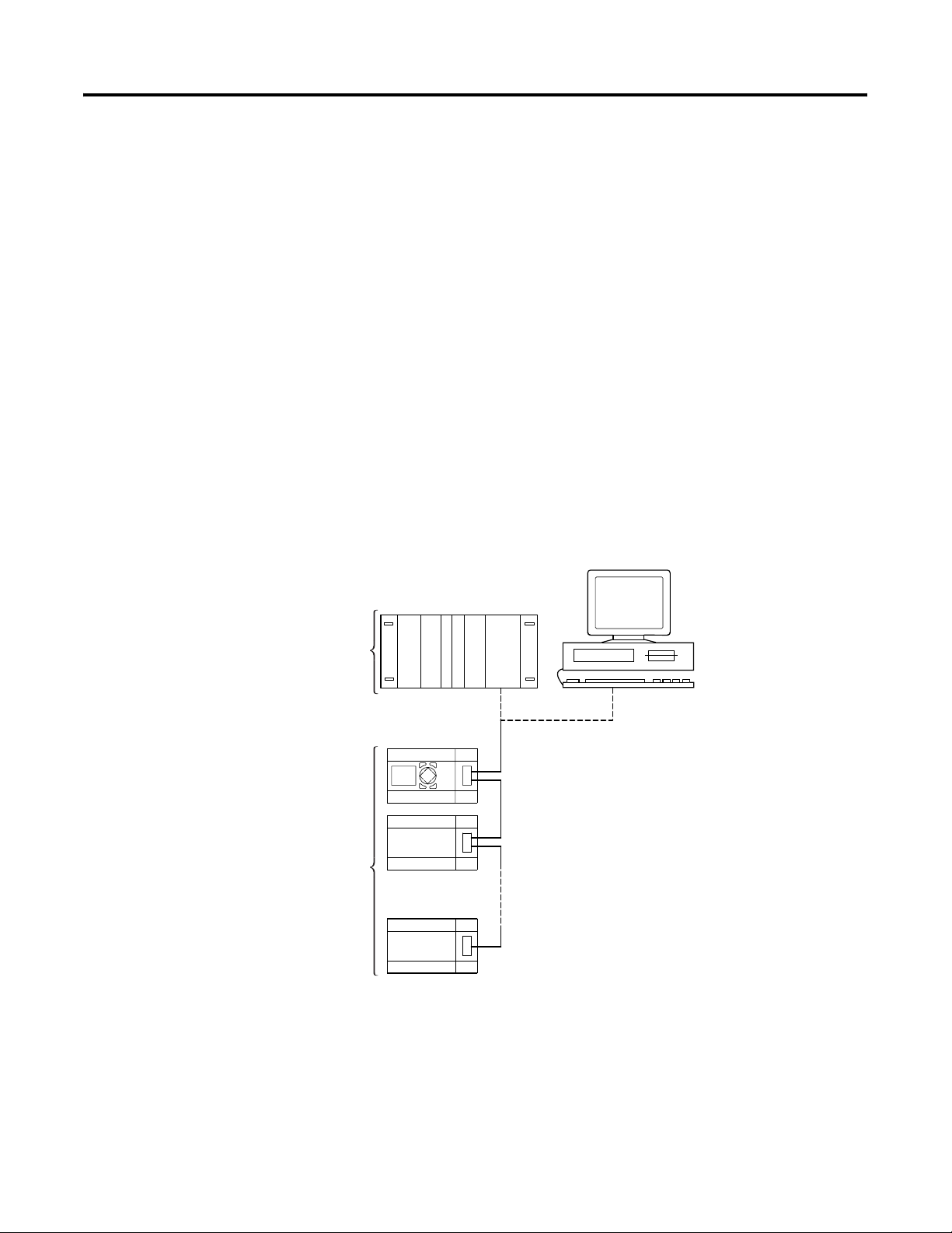
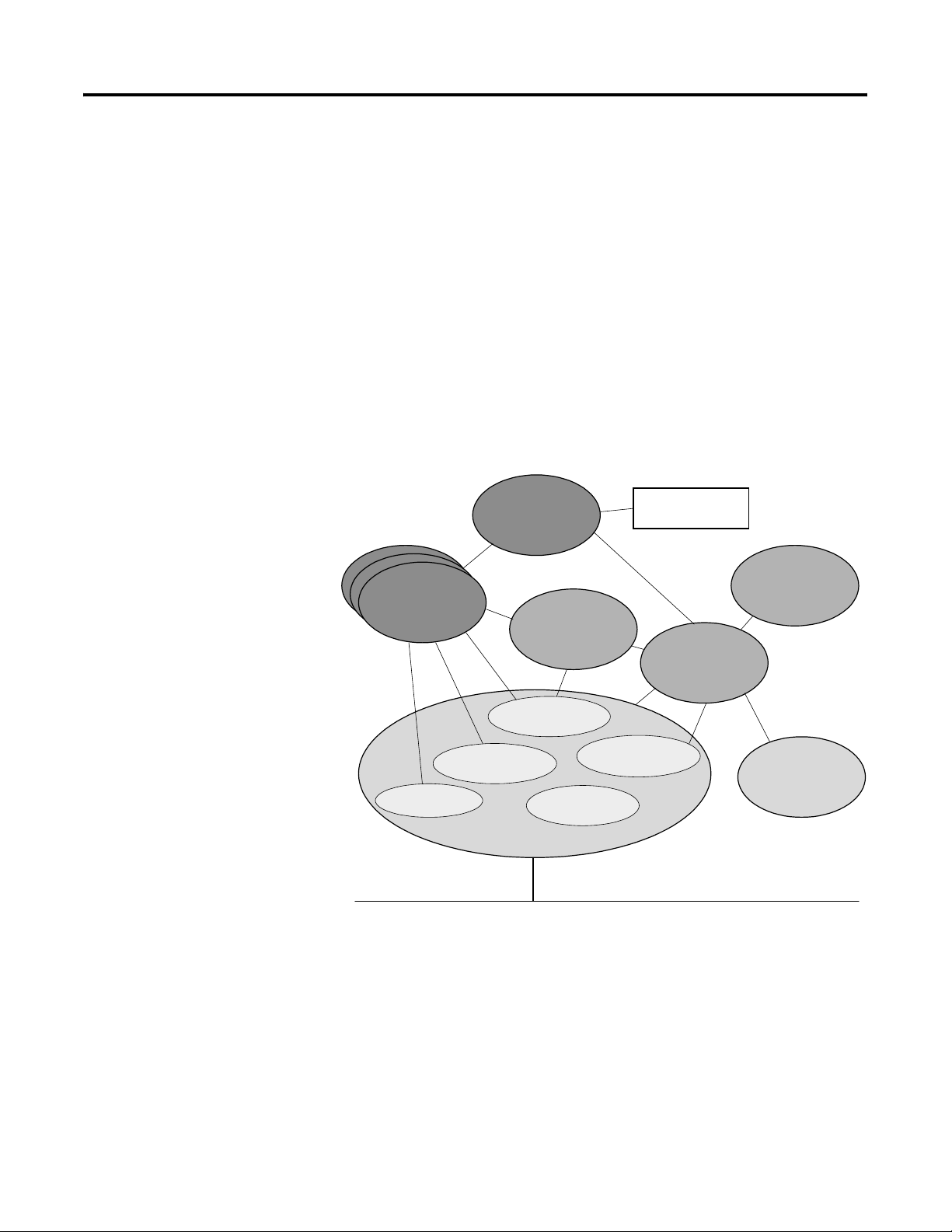
System Overview
The DeviceNet slaves are integrated into a DeviceNet fieldbus system.
Figure 1.1 Implementation of 1760-DNET in DeviceNet
a
b
a Master area, SLC 500 programmable controller or PC with CAN card
b Slave area, e.g.: Pico or Pico GFX-70 with DeviceNet interface
1 Publication 1760-UM003A-EN-P - September 2005
Page 10
1-2 Pico DeviceNet Interface
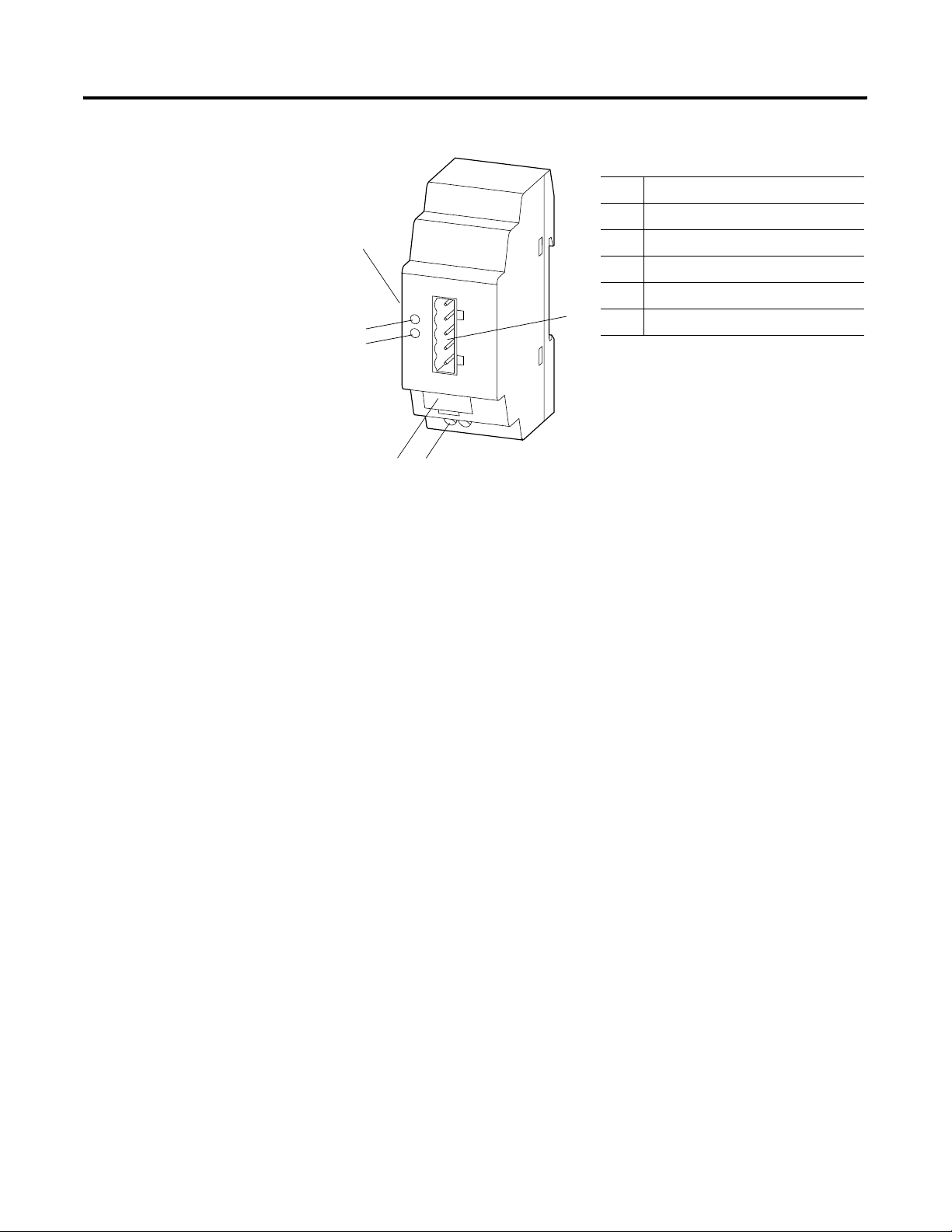
Structure of the Unit
Communication Profile
Figure 1.2
1 Pico-Link Socket
2 5-pin DeviceNet Connector
a
f
e
d
MS
NS
c
3 24V dc Power Supply
4 Equipment Rating Plate
5 Network Status LED
b
6 Module Status LED
• Predefined master/slave communication settings
– The I/O polling connection is used for the transfer of 3 bytes
of input data (R1 to R16) and 3 bytes of output data (S1 to S8)
between the base unit with gateway interconnection and the
DeviceNet programmable controller.
– The I/O Change of State/Cyclic connection (acknowledged,
unacknowledged) is used to transfer 2 bytes of diagnostic
data from the control relay to the DeviceNet programmable
controller.
– The explicit connection set-up is used for read/write access
to function relay parameters in the control relay. This type of
connection set-up also supports the configuration, diagnostics
and management services of the control relay.
• DeviceNet Communication adapter profile (device type 12),
which has been expanded by requests
• Group 2 server
• UCMM-capable device
• Dynamic set-up of explicit and I/O connections are possible
• Device Heartbeat Message
• Device Shutdown Message
• Offline communication settings
Hardware and Operating System Requirements
Publication 1760-UM003A-EN-P - September 2005
The 1760-DNET expansion unit operates together with Pico Series B
and Pico GFX-70 controllers.
Page 11

Pico DeviceNet Interface 1-3
Use Other Than Intended
Pico and Pico GFX-70 controllers may not be used to replace
safety-relevant control circuits, e.g.:
• Furnace,
• emergency-stop,
• crane or
• Two-hand safety controls.
Publication 1760-UM003A-EN-P - September 2005
Page 12

1-4 Pico DeviceNet Interface
Publication 1760-UM003A-EN-P - September 2005
Page 13
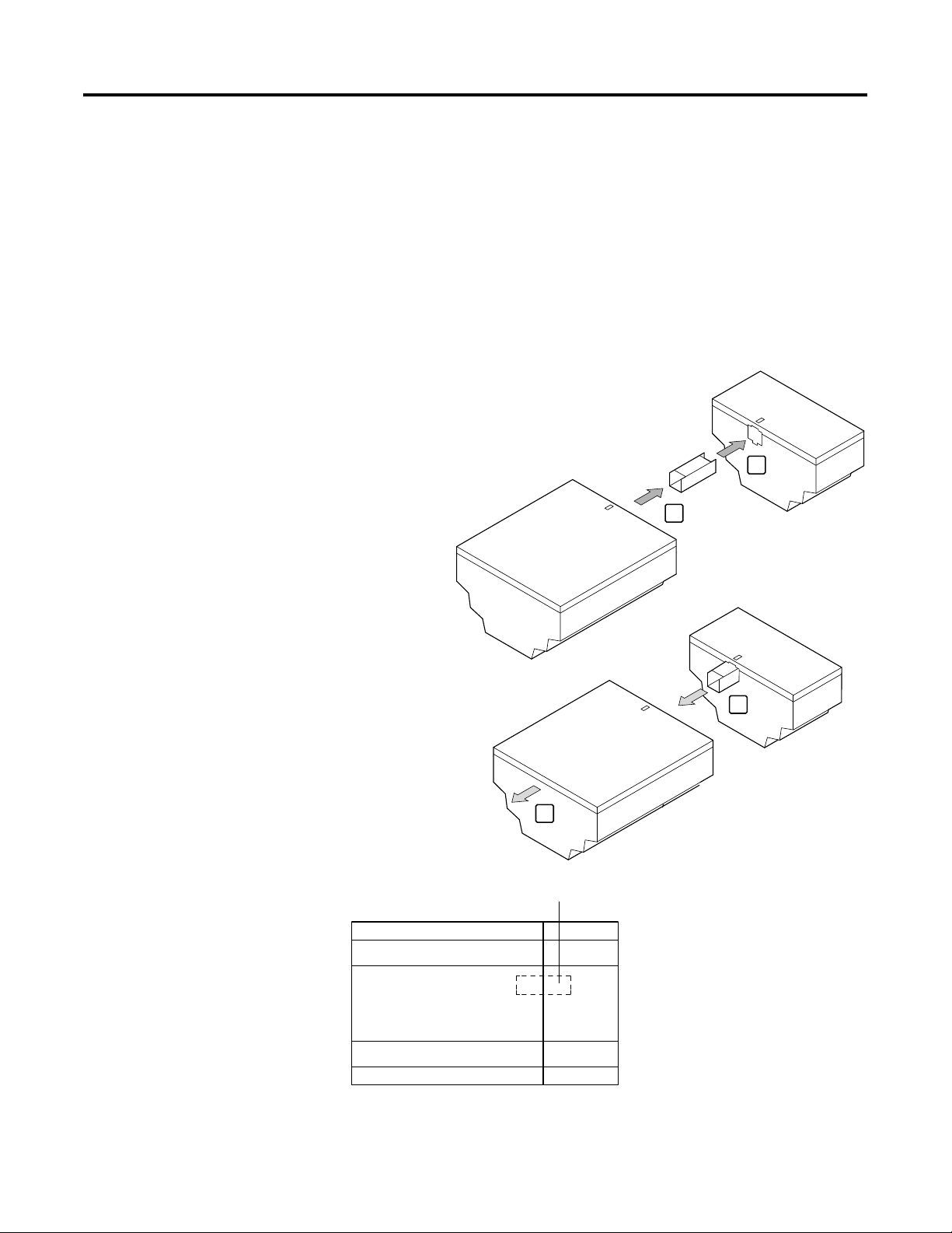
Connect to the Basic Unit
Installation
Mounting is the same as for Pico Expansion I/O modules.
1
2
Chapter
2
Pico
Pico GFX-70
4
3
connector
1760-DNET
1 Publication 1760-UM003A-EN-P - September 2005
Page 14
2-2 Installation
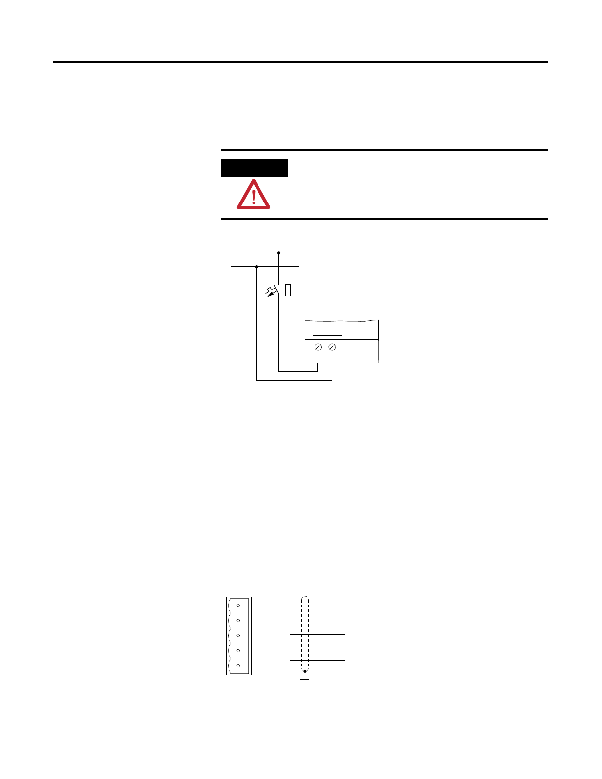
Connect the Power Supply
The module operates with a 24V dc supply voltage (see Power Supply
specifications on page A-3).
WARNING
+24 V
0 V
Always ensure safe electrical isolation between the
extra low voltage (SELV) and the 24V power supply.
> 1 A
+24 V 0 V
Connect DeviceNet
A 5-pin DeviceNet plug connects the DeviceNet interface of the
device to the DeviceNet field bus.
Use a special DeviceNet plug and DeviceNet cable for this connection.
Both are specified in the ODVA specification. The type of cable
determines the maximum available cable length and the data transfer
rate.
DeviceNet Pin Assignment
1
1
2
2
3
3
4
4
5
5
V– GND (Black)
CAN_L (Blue)
Shield (Clear)
CAN_H (White)
V+ (24 V) (Red)
Publication 1760-UM003A-EN-P - September 2005
Page 15
Installation 2-3
All pins of the plug must be connected to ensure safe communication
of the
1760-DNET on the fieldbus DeviceNet. This also applies to the
24V bus voltage.
EMC Compatible Wiring
IMPORTANT
The gateway does not participate in communication
on the bus if the bus voltage is not available. The
Network status LED is OFF in this situation.
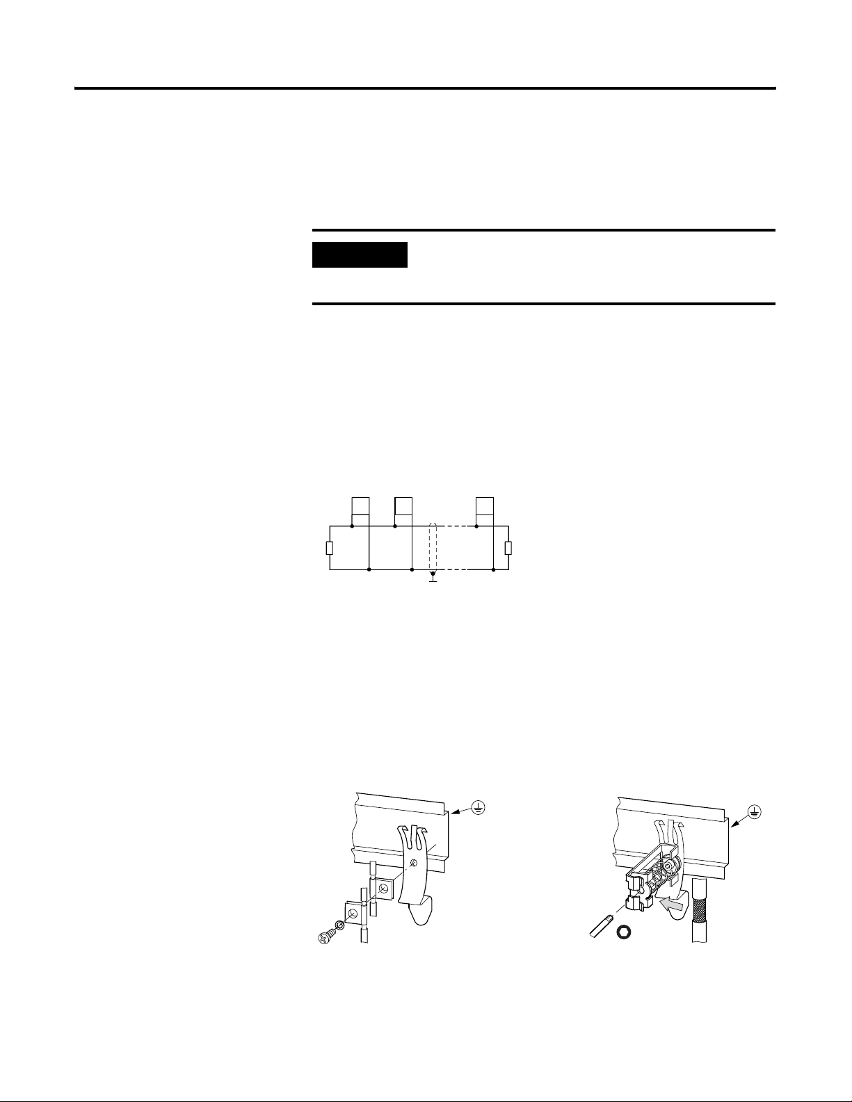
Terminating Resistors
The first and last node of a DeviceNet network must be terminated by
means of a 120 O
interconnected between the CAN_H and CAN_L terminals.
0
R
T
Electromagnetic interference may lead to unwanted effects on the
communications fieldbus, which can be significantly reduced by using
the cable described above, a shielded RJ45 connector and by
terminating the screen.
bus termination resistor. This device is
. . .
1
n
R
T
The two figures below show the correct termination of the shielding.
Figure 1.3 Shield Connection to the Mounting Rail
Publication 1760-UM003A-EN-P - September 2005
Page 16
2-4 Installation
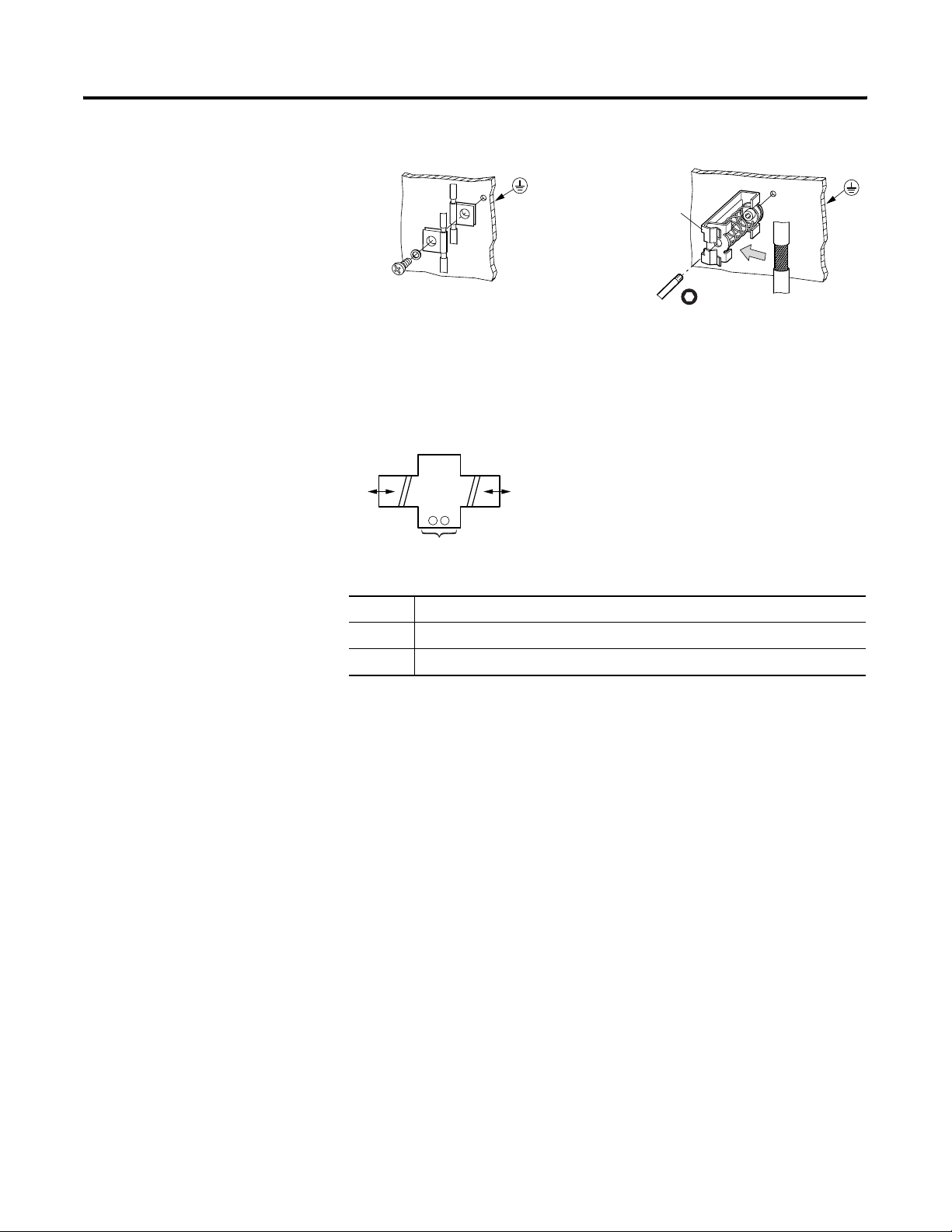
Figure 1.4 Shield Connection to the Mounting Plate
Potential Isolation
Data Transfer Rates –
Automatic Baud Rate
Recognition
The following potential isolation specifications apply to 1760-DNET
interfaces:
a
+ –
c
1 Safe electrical isolation between PicoLink and the 240 VAC mains
2 Simple electrical isolation to the DeviceNet communication bus
3 Power supply 24 V DC
After it is switched on, the 1760-DNET module automatically detects
the data transfer rate of the communication network. However, this is
possible only if at least one network node transmits valid message
frames. The device supports the following data transfer rates
according to ODVA:
b
Publication 1760-UM003A-EN-P - September 2005
• 125 kbps,
• 250 kbps,
• 500 kbps,
Maximum Distances and Bus Cable Lengths
The max. bus length is not determined by the data transfer rate, but
rather by the cable used. The following cables are permitted:
• Thin Cable,
• Thick Cable
Page 17

• or Flat Cable.
The data cable requirements are specified by the ODVA.
Baud Rate (kbps) Maximum Cable Length (m)
Thick Cable Thin Cable Flat Cable
125 500 100 420
250 250 100 200
500 100 100 100
Installation 2-5
Publication 1760-UM003A-EN-P - September 2005
Page 18

2-6 Installation
Publication 1760-UM003A-EN-P - September 2005
Page 19

Operate the DeviceNet Interface
Chapter
3
Initial Power On
DeviceNet Setting the Slave Address
Before you apply power to the DeviceNet Interface, verify that it is
properly connected to the power supply, to the bus connectors and to
the basic unit. Then, switch on the power supply for the basic unit
and the DeviceNet Interface.
The LEDs of the 1760-DNET flicker.The device automatically detects
the correct baud rate (see Data Transfer Rates – Automatic Baud Rate
Recognition on page 2-4). The GW information (intelligent station
connected) is displayed on the basic unit.
When the device in the network management is switched to the
‘Operational’ status, the state of the GW changes to static even on the
devices with a flashing GW,(see Network Status LED (NS) on
page 3-5).
If the unit has default configuration (node ID = 127), you need to
define the DeviceNet slave address.
Each DeviceNet slave requires a unique address (MAC ID) in the
DeviceNet structure. Within a DeviceNet structure, you can assign a
maximum of 64 addresses (0 to 63). Each MAC ID must be unique
within the entire bus structure.
There are three ways to set the DeviceNet address of an 1760-DNET:
• Using the integrated display and keyboard on the basic unit
• Using Pico-Soft V3.01 or higher on the PC
• Using Pico-Soft Pro on the PC
• Using the configuration software of the installed master
programmable controller (possibly by means of an explicit
message).
Set the Address on the Controller Unit with Display:
Make sure that:
• The respective basic units and DeviceNet Interface are supplied
with voltage.
1 Publication 1760-UM003A-EN-P - September 2005
Page 20

3-2 Operate the DeviceNet Interface
• The basic unit is accessible (password protection not activated).
• The basic unit has a valid operating system version.
• The basic unit is in STOP mode.
+
PASSWORD...
SYSTEM...
GB D F E I
CONFIGURATOR
PASSWORD...
SYSTEM...
GB D F E I
CONFIGURATOR
NET...
LINK...
1. Press the DEL + ALT keys to change to the special menu.
2. Use the cursor keys
Í or Ú to change to the Configurator.
3. Press OK.
4. Select the LINK.... menu with the Pico-GFX units.
5. Press OK.
DEVICENET
MAC ID 0026
222-01.20- D
Publication 1760-UM003A-EN-P - September 2005
The DEVICENET menu appears.
6. Set the address using the cursor keys:
– Set the current numeric value using the
– You can change the current numeric value using
2 . . . 9 0
1 . . .
o
0 0 01PP000
o
1 0 9 . . .
2 . . .
Í or Ú keys.
ú or í.
1
Page 21

7. Press OK to accept the address.
8. Press ESC to cancel address input.
Information about the 4th display line:
xxx -x x . x x - xx
222 - 02 . 10 - B
Set the Address with Pico-SOFT
With Pico-SOFT, version 3.1
Operate the DeviceNet Interface 3-3
Hardware version, Index: b
Software version, OS version: 2.1
Device identity: 1760-DNET
‹Menu l Online l Configuration of expansion units›
With Pico-SOFT, version 4.01 and later
‹Menu l Communication l Configuration l Expansion units l
1760-DNET›.
IMPORTANT
IMPORTANT
The menu is only available in the communication
view; therefore please activate the ‘Communication’
tab.
After you have modified the MAC ID via the basic
unit, restart the DeviceNet Interface by switching
power off and on.
Set the Address with the DeviceNet Master
The configuration software supplied with your master programmable
controller offers the option of setting or modifying the MAC ID of the
gateway.
Publication 1760-UM003A-EN-P - September 2005
Page 22

3-4 Operate the DeviceNet Interface
For more information, refer to the programmable controller’s
documentation.
You can also use various other software packages to modify the MAC
ID by sending an explicit message. Do so by using the corresponding
service of the DeviceNet object (see DeviceNet Object on page 4-6).
LED Status Displays
The DeviceNet Interface expansion module is equipped with two
indicator LEDs for quick diagnostics. The module monitors itself as
well as the DeviceNet communication bus.
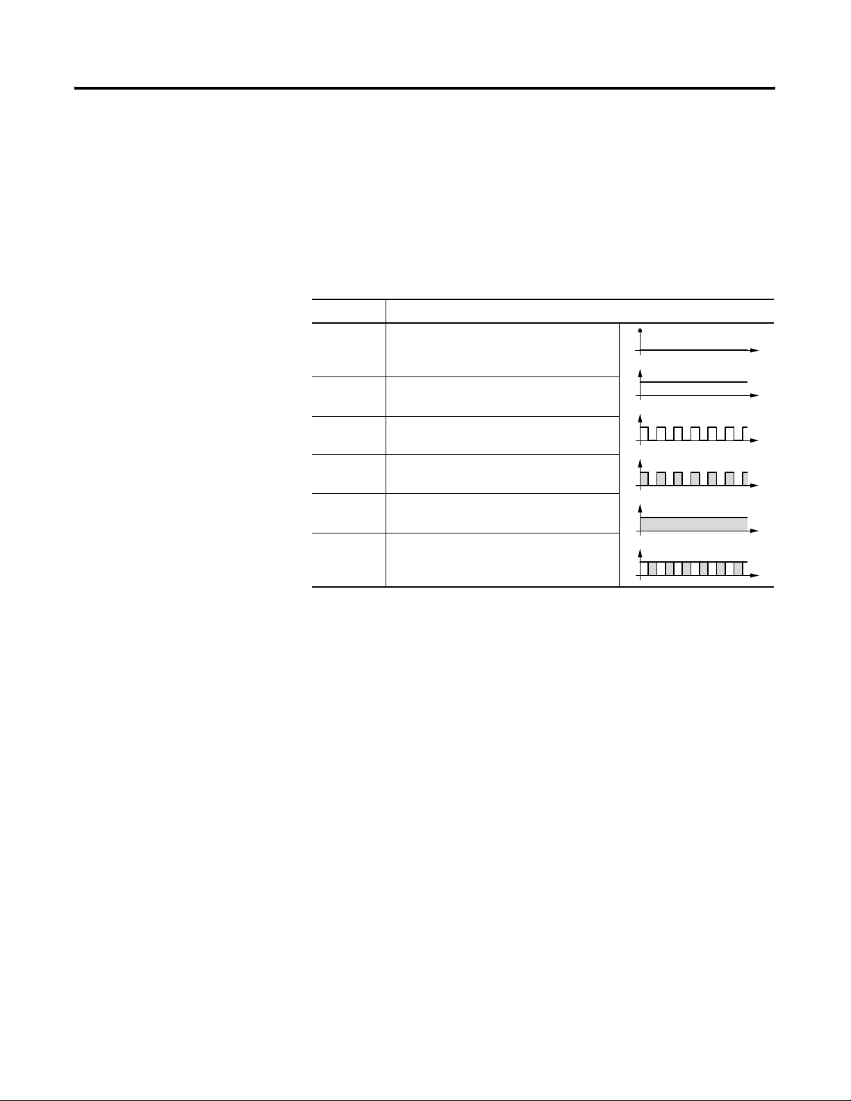
Module Status LED (MS)
The dual-color LED (GREEN/RED) indicates the status of the module.
It monitors whether the device is fully functional and operates without
fault.
Table 3.1 Module Status LED Description
LED Status Description
Off No power supply at the module.
Green The module is in normal operational
state.
Green flashing The module is in standby mode. The
configuration is faulty or incomplete,
or a configuration does not exist.
t
t
Publication 1760-UM003A-EN-P - September 2005
Red flashing An error has occurred. There is no
need to replace the module.
Red A fatal error has occurred. The
module must be replaced.
Green-Red flashing The module is performing a self-test.
t
t
t
t
Page 23
Operate the DeviceNet Interface 3-5
Network Status LED (NS)
The dual-color LED (GREEN/RED) indicates the status of the
DeviceNet communication bus. This function monitors operability and
correct operation of the module.
Table 3.2 Network Status LED Description
LED Status Description
OFF The module is offline. Either it is performing
a DUP_MAC_ID test or power is missing at
the device or bus.
GREEN
flashing
GREEN The module is online and the connection is
RED
flashing
RED A fatal network error has occurred. The
GREEN-RED
flashing
The module is online. Communication has
not yet been established.
active.
Time-out of at least one I/O connection
(time-out state).
module has shut down communication.
The module has detected a network access
error and is now in communication error
state.
t
t
t
t
t
Cycle Time of the Pico Basic Unit
EDS File
Network traffic between the Pico basic unit and the DeviceNet
Interface via Pico-LINK extends the cycle scan time of the basic unit
In the worst case, this time can be extended by 25 ms.
Please take this factor into account when you calculate the response
times of the basic unit.
You can implement the module into the DeviceNet structure by means
of a standardised EDS file (Electronic Data Sheet).
This EDS file primarily defines the polled I/O connection, the COS I/O
connection and the cyclic I/O connection of the gateway. It does not
contain data or parameters (Pico object) for functions of the controller.
These functions are accessed by means of explicit messages.
You can download updates of the EDS file from:
http://www.ab.com/networks/eds/
Publication 1760-UM003A-EN-P - September 2005
Page 24

3-6 Operate the DeviceNet Interface
Search for the catalog number 1760.
IMPORTANT
The Identity Object entry - Major Revision defines
the current operating system state of the 1760-DNET
communication module. As the device with a newer
operating system version can deviate from the EDS
description in this point, this entry must be modified
accordingly, Identity Object on 4-4.
Publication 1760-UM003A-EN-P - September 2005
Page 25
DeviceNet Functions
Chapter
4
Object Model
The Pico DeviceNet Interface is based on the Communications
Adapter Profile according to the ODVA specifications (Release V2.0).
The DeviceNet object model can be used to describe all 1760-DNET
functions. The object model reflects the principle of communication at
the application layer. This manual deals in the following only with
objects relevant for your application. Primary topic is the
manufacturer-specific class Pico object.
Figure 3.5 DeviceNet Objects
Pico-LINK
Protocol Handler
Identity
Object
Message Router
Object
DeviceNet
Object
Assembly
Object
Object
Polled I/O
Connection
COS/Cyclic I/O
Bit Strobed I/O
Connection
Pico
Object
Acknowledge Handler
Object
Connection
Explicit Message
Connection
Dynamic
Connection
Connection Object
DeviceNet
The DeviceNet objects in the illustration can be compiled again as
‘Management objects’, ‘Connection objects’ and ‘Manufacturer-specific
objects’.
1 Publication 1760-UM003A-EN-P - September 2005
Page 26

4-2 DeviceNet Functions
Table 3.3
Objects Object Address Service Address Function
Class ID (Hex) Instance ID (Hex) (Hex) Attribute ID (Hex)
Management Objects
Identity Object 01 01
Message Router 02 01
Connection Objects
DeviceNet Object 03 01
Connection
Object
Manufacturer-Specific
Objects
Pico Object 64 01
Direct Access:
inputs/outputs,
mode
Read 0E
Write 10
Extended access:
time, image data,
function blocks
Pico Series B
Pico GFX-70
Assembly Object 04 64 ... 66
05 01 ... 04,
04 ... 0F
Management Objects
32
Publication 1760-UM003A-EN-P - September 2005
These objects define DeviceNet-specific data and functions and must
be supported by all DeviceNet devices:
• Identity Object
The Identity Object (Class ID 01
) contains all data for unique
hex
identification of a network node, e.g. the Vendor ID, Device
Type and Product Code. It also comprises the actual status of a
device, the serial number and the product name.
Detailed information can be found on page 4-4.
Page 27

• Message Router Object
DeviceNet Functions 4-3
The Message Router Object (Class ID 02
) provides access to
hex
all classes and instances in the device by means of explicit
messages.
Connection Objects
These objects define messages exchanged via DeviceNet:
• DeviceNet Object
All devices must support the DeviceNet object (Class ID: 03
It defines the physical interconnection of a device to the
DeviceNet network, meaning it also contains the device address
(MAC ID) and the currently set transmission speed, for example.
Detailed information page 4-6.
• Connection Object
The Connection Object (Class ID: 05
DeviceNet devices in at least one instance. It defines the access
to data via I/O messages or explicit messages, the path and
length of producer/consumer data, the CAN connection
identifier, the watchdog and the error response.
) is supported by all
hex
hex
).
Publication 1760-UM003A-EN-P - September 2005
Page 28

4-4 DeviceNet Functions
Manufacturer-Specific Objects
These objects define device-specific data and functions (Application
Objects, Parameter Object, Assembly Object).
• Application Objects – Pico Object
Application objects (Class ID: 64
) describe simple
hex
applications for automation engineering. They are either
predefined in the DeviceNet object library or by the user.
Refer to Pico Object on page 4-6.
• Assembly Objects
The Assembly Object (Class ID: 04
) provides the user with
hex
mapping options, that is attribute data of different instances in
different classes can be grouped together to form a single
attribute of an instance in an assembly object.
Identity Object
Object Address Function Access
Class ID Instance ID Attribute ID Service Code
01
hex
01
hex
Table 4.4 Table 4.5
Publication 1760-UM003A-EN-P - September 2005
Table 4.4 Attribute IDs of the Identity Object Instance
Attribute IDAccess Name Description Size
(byte)
1 Read Vendor ID Allen-Bradley Vendor ID = 1 2
2 Read Device type The 1760-DNET belongs to the
communication adapters category. Its
value is 12
3 Read Product code Allen-Bradley product code = 18410 2
dec
.
2
Page 29

DeviceNet Functions 4-5
Table 4.4 Attribute IDs of the Identity Object Instance
Attribute IDAccess Name Description Size
(byte)
4 Read Device
version
Two bytes are returned when reading the
device version.
Hardware
version,
Operating
The low byte defines the hardware
version, the high byte the operating
system version.
1
1
system
version
5 Read Status This attribute describes the global status
2
of the device.
6 Read Serial
number
7 Read Product name The product name 1760-DNET is stored as
The serial number of the device can be
read with this attribute.
4
12
hex value in ASCII format.
9 Read Configuration
consistency
value
10 Read/
Write
Heartbeat
Interval
This attribute returns a counter value that
monitors the number of modifications in
non-volatile memory (E2PROM).
Defines an interval between heartbeat
messages in [s].
2
2
Service Code
The Identity Object Instance and also the following instances support
the services listed in the table below.
Table 4.5 Service Code
Service Code Value Service Name Description
05
hex
Reset Calls the reset function of
the communication module.
0E
hex
Get_Attribute_Single This service can be used to
fetch the value of a selected
attribute from the
communication module.
10
hex
Set_Attribute_Single This service can be used to
set a selected attribute in
the device.
Publication 1760-UM003A-EN-P - September 2005
Page 30

4-6 DeviceNet Functions
DeviceNet Object
Object Address Function Access
Class ID Instance ID Attribute ID Service Code
03
hex
The DeviceNet object instance is used to configure the
communication module and to define the physical environment. The
Service Codes used for the Identity Object also apply in this case.
Table 4.6 DeviceNet Object Instance Attribute IDs
Attribute IDAccess Name Description Size
01
hex
Table 4.6 Table 4.5
(byte)
1 Read/
Write
2 Read/
Write
3 Read/
Write
4 Read/
Write
Pico Object
MAC ID The MAC ID represents the network
address of a network node. It can be read
and set for the module via the DeviceNet
fieldbus by means of this attribute. Range
of values: 0 to 63
Setting the Slave Address on page 3-1)
Baud rate This attribute can be used to read/set the
data transfer rate for communication
functions. Range of values: 0 to 2, 125 to
500 kbps (see Data Transfer Rates –
Automatic Baud Rate Recognition on page
2-4).
BOI (Bus-Off
interrupt)
Bus-Off
counter
This attribute can be used to define the
reaction to a Bus-Off event (CAN-specific).
This values shows how often a Bus-Off
event has occurred. Range of values: 0 to
255.
. (see DeviceNet
dec
1
1
1
1
Publication 1760-UM003A-EN-P - September 2005
Object Address Function Access
Class ID Instance ID Attribute ID Service Code
64
hex
01
hex
Table 4.7 Table 4.8
The Pico object can be used to access Pico/GFX functions via the
DeviceNet communication bus . The table below shows the attributes
Page 31

DeviceNet Functions 4-7
supported by this object. The two bytes of attributes 1 and 2 provide
the diagnostic data of the device. You can use attribute 3 to access the
outputs (S1 to S8) and attribute 4 to access the inputs (R1 of R16) of
the basic unit.
By using a DeviceNet configuration software (e.g. RSNetworx), you
can map these data directly to the corresponding memory areas of a
programmable controller.
Table 4.7
Attribute IDAccess Name Description Size
(byte)
1 Read Pico Status This attribute can be used to read the
status of Pico (RUN or STOP). See
Table 4.9.
2 Read Coupling
Module
Status
This attribute can be used to read the
status of Pico-LINK. See Table 4.9.
1
1
3 Read Inputs –
Send Data
4 Read/W
rite
5 Read/W
rite
Outputs –
Receive Data
Predefined
Outputs
Pico transfers the input data to the
DeviceNet bus. The Pico outputs S1 to S8
must be used for this function. The
structure of these 3 bytes is described in
detail under Input data: Mode, S1 – S8 on
page 5-2, .
The DeviceNet bus transfers the data to
Pico. The Pico inputs R1 to R16 must be
used for this function. The structure of
these 3 bytes is described in detail under
Output Data: Mode, R1 – R16 on page 5-4,
.
This attribute can be used to preset the
output data ("R" data) at the
1760-DNETduring start-up. The structure
of these 3 bytes is described in detail
under Output Data: Mode, R1 – R16 on
page 5-4.
Service Code
The Pico object instance supports the following services.
3
3
3
Publication 1760-UM003A-EN-P - September 2005
Page 32

4-8 DeviceNet Functions
Table 4.8 Service Code
Service Code Value Service Name Description
0E
hex
Get_Attribute_Single This service can be used to
fetch the value of a selected
attribute from the
communication module.
10
hex
Set_Attribute_Single This service can be used to
set a selected attribute in
the device.
32
hex
Extended access
(1)
This service can be used to
address the supplementary
parameters
(1)
of the control
relay:
(1) Additional parameters are “Time”, “Image data” and “Function block”. Addressing of the parameters is Pico
specific and is described in chapters 5 – 7 in detail.
Extended access is implemented via explicit message transfer. This transfer protocol allows the exchange of
control data. Further information about the transfer protocol can be found in section “DeviceNet
Communication profile” on page 9.
Change of State I/O Connection
Table 4.9 Diagnostics Data: 2 Byte
Bytes Meaning Value Meaning
0 Pico status
(attribute ID 1)
1 Coupling module
status (attribute ID
2)
TIP
When communication between the basic unit
Pico/GFX and the expansion unit 1760-DNET goes
down, a corresponding error code will be generated
in the third data byte. Furthermore, the Rx/Tx data of
the gateway will be transferred with the value 00hex.
00
00
04
hex
hex
hex
Static value.
The basic unit is
connected to the
1760-DNET gateway
via Pico-LINK.
The basic unit is
either switched off
or disconnected
from the
1760-DNET gateway
via Pico-LINK.
Publication 1760-UM003A-EN-P - September 2005
Page 33

DeviceNet Functions 4-9
DeviceNet Communication Profile
DeviceNet is based on a connection-oriented communications model,
that is data are exchanged only via the specific connections assigned
to the units.
DeviceNet stations communicate either by means of I/O messages or
explicit messages.
I/O Messages
I/O messages are used for exchanging high-priority process and
application data across the network. Communication between
DeviceNet nodes is based on the client/server model, i.e. a "producer"
application transfers data to one or several "consumer" applications. It
is quite possible in this case that several application objects are
addressed in the same unit.
Prerequisite for communication between the units via I/O messages is
the implementation of an I/O Messaging Connection Object. You can
activate this function in two ways:
• Either by means of a static and in the unit already existing ‘I/O
connection object’ or via the ‘Predefined Master/Slave
Connection Set’, or
• via a dynamically configured ‘I/O connection object’, which you
can configure using an Explicit Messaging Connection Object
that already exist in the unit.
Explicit Messages
Explicit messages are used for exchanging low-priority configuration
data, general management data or diagnostics data between two
specific units across the PtP connection in a client/server system, in
which the server always has to acknowledge client requests.
Same as for I/O messaging, the prerequisite for explicit messaging is
the implementation of a Connection Object, namely the Explicit
Messaging Connection Object. This can be achieved either by
activating an existing static connection object in the unit, or via the
Predefined Master/Slave Connection Set, or dynamically across the
UCMM port (Unconnected Message Manager Port) of a device.
All data of the function relay (Pico basic unit) are processed by means
of explicit messages. The DeviceNet master can thus read/write access
the parameters of the following functions.
Publication 1760-UM003A-EN-P - September 2005
Page 34

4-10 DeviceNet Functions
• Time
• Image data
• Function blocks (counters, timers, analog value comparators,...).
General Method of Operation
The general method of operation with the 1760-DNET should be
presented in the following. The acyclic data transfer is realised with
the aid of explicit messages. The function blocks of the Pico basic unit
can be addressed via the service code = 32
ID is here used to distinguish between different parameters and
functions.
Service Code Object Address
Class ID Instance ID
. The assigned attribute
hex
32
hex
64
hex
01
hex
Digression:
DeviceNet based on the standard CAN protocol and therefore uses an
11 bit message identifier. As a result 211 = 2048 messages (000
7FF
) are distinguishable. Six bits are sufficient for identification of a
hex
hex
-
device as a DeviceNet network is limited to a maximum of 64 stations.
These are referred to as the MAC-ID (device or node address).
Four message groups of differing sizes are available to suit the
utilization model.
In DeviceNet language terms the CAN identifier is referred to as the
Connection ID. This is comprised of the identifier for the message
group (Message ID) and the MAC ID of the device:
• The source and target addresses are possible as the MAC ID; the
definition is dependant on the message group and message ID.
• The significance of the message is defined in the system with the
message ID.
Four message groups are available in the DeviceNet world. The
1760-DNET uses message group 2. This group uses 512 CAN
identifiers (400
hex
- 5FF
). Most of the message IDs defined for this
hex
group are optional and defined for use of the ‘Predefined Master/Slave
Connection Sets’. A message ID is used for network management. The
priority is primarily determined by the device address and then by the
message ID. If the bit position is examined in detail, you will find that
a CAN controller with an 8 bit mask is capable of filtering out its
group 2 messages.
Publication 1760-UM003A-EN-P - September 2005
Page 35

DeviceNet Functions 4-11
Connection ID = CAN Identifier Meaning
109876543210
1 0 MAC ID Message ID Message Group 2
1 0 Source MAC ID 0 0 0 Master’s I/O Bit-Strobe Command
Message
1 0 Source MAC ID 0 0 1 Reserved for Master’s Use - Use is
TBD
1 0 Destination MAC ID 0 1 0 Master’s Change of State or Cyclic
Acknowledge Message
1 0 Source MAC ID 0 1 1 Slave’s Explicit/Unconnected
Response Messages
1 0 Destination MAC ID 1 0 0 Master’s Explicit Request Messages
1 0 Destination MAC ID 1 0 1 Master’s I/O Poll Command/Change
of State/Cyclic Message
1 0 Destination MAC ID 1 1 0 Group 2 Only Unconnected Explicit
Request Messages
1 0 Destination MAC ID 1 1 1 Duplicate MAC ID Check Messages
The data transfer on the DeviceNet communication bus is indicated in
the following table. The data flow indicates the telegram for reading
the date and time in the Pico (see Read/Write Date and Time on page
6-2).
The Pico DeviceNet communication module has MAC ID = 3. It must
be noted with the data stream that access is implemented in
fragmented form. More information can be found in the ODVA
specification.
Description ID
(Hex)
Master sends a request (Hex) with: 41C 8 80 00 32 64 01 93 05 00
DeviceNet Specific:
Byte 2 - Service Code = 32
Byte 3 - CLASS ID = 64
Byte 4 - Instance ID = 01
PicoLINK Specific
Length DeviceNet - Byte (Hex)
01234567
Byte 5 - Attribute ID = 93
Byte 6 - Len = 05
Byte 7 - Index = 0
Confirmation of the slave
(Fragmentation protocol)
41B 3 80 C0 00
Publication 1760-UM003A-EN-P - September 2005
Page 36

4-12 DeviceNet Functions
Description ID
(Hex)
Master sends remaining PicoLINK
41C6 800100000000
Length DeviceNet - Byte (Hex)
01234567
byte
Byte 2 - Data 1 = 00
Byte 3 - Data 2 = 00
Byte 4 - Data 3 = 00
Byte 5 - Data 4 = 00
Acknowledgement of the slave
41B 3 80 C1 00
(Fragmentation protocol)
Slave sends a response to the request 41B 8 80 00 B2 C2 05 00 05 09
Byte 3 – response = C2 (read
successful)
Byte 4 – Len = 05
Byte 5 – Index = 00
Byte 6 – Data 1 = 05
Acknowledgement from master
41C 3 80 C0 00
(Fragmentation Protocol)
Slave sends remaining Pico-LINK
41B5 80810D0504
data:
Data 2 = 0D
Data 3 = 05
Data 4 = 04
Acknowledgement from master
(Fragmentation protocol)
41C 3 80 C1 00
Publication 1760-UM003A-EN-P - September 2005
Page 37

Chapter
5
Direct Data Exchange with Pico/GFX (Polled
I/O Connection)
The DeviceNet master can exchange the following data with the
Pico/GFX via the direct cyclic data exchange:
TIP
• Write operation
– Setting or /resetting of the Pico/GFX inputs (R1 to R16)
– Determination of the RUN/STOP mode.
• Read operation
– Scanning the output states of the Pico/GFX (S1 to S8)
– Scanning the mode of the Pico/GFX.
In order to transfer data between the slave 1760-DNET and a
DeviceNet master control, you must map the respective cyclic data to
the respective slave configuration.
TIP
The terms “input data” and “output data” are used
relative to the point of view of the DeviceNet master.
The interconnection to the DeviceNet controls from
Allen Bradley is implemented using an assignment
table in the RSNetWorx software tool.
1 Publication 1760-UM003A-EN-P - September 2005
Page 38

5-2 Direct Data Exchange with Pico/GFX (Polled I/O Connection)
Figure 4.6 Input and Output Data Relative to the DeviceNet Master
DeviceNet Master
Outputs
Inputs
Input data: Mode, S1 to S8
Write: Output
data
Inputs
R1 – R16
Pico/GFX
Outputs
S1 – S8
Read: Input data
Attribute ID: 3
The cyclic data transfer between DeviceNet master and the Pico
DeviceNet Interface slave is provided by the input data byte 0, 1 and
2.
IMPORTANT
If Index for transferring valid data is not set, you
cannot read the S1 to S8 bits in RSLogix 5000.
Publication 1760-UM003A-EN-P - September 2005
Table 5.10 Byte 0 to 2: Input Data, Mode
Byte Meaning Value
0 Operating mode scan
1 Scan status of the Pico
outputs S1 to S8
2 Not used 00hex
The master reads the following data from bytes 0, 1 and 2:
Page 39

Direct Data Exchange with Pico/GFX (Polled I/O Connection) 5-3
Table 5.11 Byte 0: Operating Mode
Pico
Identification
Without Input
Delay
With Input Delay 0 0 1 0 0 0 0 0/1
Index for
transferring valid
data
Bit
76543210
Stop/Run
00010000/1
00010100
0 = status ’0’ 1 = status ’1’
Explanation:
Value 14
= 00010100
hex
bin
:
Byte 0 must always contain this value if data are to be written to the
Pico/GFX basic unit via the 1760-DNET gateway.
EXAMPLE
Value 21hex = 0010 0001bin:
"Pico" is in RUN mode and operates with input delay
Table 5.12 Byte 1: Status of the Pico/GFX outputs S1 to S8
Pico/GFX Bit
76543210
S1 0/1
S2 0/1
S3 0/1
S4 0/1
S5 0/1
S6 0/1
S7 0/1
S8 0/1
0 = status "0“ 1 = status "1"
Publication 1760-UM003A-EN-P - September 2005
Page 40

5-4 Direct Data Exchange with Pico/GFX (Polled I/O Connection)
EXAMPLE
Byte 2: not used
TIP
Value 19hex = 0001 1001bin:
S5, S4 and S1 are active
If control commands and I/O data are used at the
same time:
• The inputs will retain their previous state until
this control command has been executed.
• The input bytes will be updated again after the
data exchange control command has been
terminated.
If the status value of the coupling module is invalid
(= 04hex), then byte 1 (data byte) is transferred with
the value 00hex to the communication bus.
Output Data:
Mode, R1 – R16
Attribute ID: 4
The cyclic data transfer between DeviceNet master and the Pico
DeviceNet Interface slave is provided by the output data byte 0, 1 and
2.
Table 5.13 Byte 0 to 2: Output Data, Mode
Byte Meaning Value
0 Determine mode
1 Setting/resetting of the
Pico/GFX inputs R9 to R16
2 Setting/resetting of the
Pico/GFX inputs R1 to R8
The master writes the following data to the bytes 0, 1 and 2:
Publication 1760-UM003A-EN-P - September 2005
Page 41

Direct Data Exchange with Pico/GFX (Polled I/O Connection) 5-5
Table 5.14 Byte 0: Operating mode
Pico Operating Mode Bit
76543210
Index for setting the
basic unit to safety
state
Index for transferring
valid data
RUN command 00110100
STOP command 01000100
00000000
00010100
0 = status ’0’ 1 = status ’1’
Explanation:
Value 14
= 00010100
hex
bin
:
Byte 0 must always contain this value if data are to be written to the
Pico/GFX basic unit via the 1760-DNET gateway.
Value 34
= 00110100
hex
bin
:
This value sets the Pico status from STOP to RUN. It is only
interpreted as command and therefore does not permit an additional
transfer of data. The index value 14
Value 44
= 01000100
hex
bin
:
must be used in this situation.
hex
This value sets the "Pico" status from RUN to STOP. It is also used only
as command and is therefore based on the same operating principle
as the RUN command.
Value 00
= 00000000
hex
bin
:
If this value is written to the control byte, the gateway overwrites the
R data with zero. This function is of interest only if a master is to be
set to STOP mode and as resultant measure transfers zero values to all
I/O in order to ensure safety state.
TIP
Even if the I/O of a control relay can be assigned
directly to a specific memory area of the master
programmable controller, it is nonetheless important
to conform with the correct data structure format
(e.g.: input data byte 0 = 14hex).
Publication 1760-UM003A-EN-P - September 2005
Page 42

5-6 Direct Data Exchange with Pico/GFX (Polled I/O Connection)
Table 5.15 Byte 1: Setting/resetting of the Pico/GFX inputs R9 to R16
Pico/GFX Bit
76543210
R9 0/1
R10 0/1
R11 0/1
R12 0/1
R13 0/1
R14 0/1
R15 0/1
R16 0/1
0 = status ’0’ 1 = status ’1’
EXAMPLE
Value 19hex = 0001 1001bin:
Enable R13, R12 and R9.
Table 5.16 Byte 2: Setting/resetting of the Pico/GFX inputs R1 to R8
Pico/GFX
Input
R1 0/1
R2 0/1
R3 0/1
R4 0/1
R5 0/1
R6 0/1
R7 0/1
R8 0/1
Bit
76543210
0 = status ’0’ 1 = status ’1’
Publication 1760-UM003A-EN-P - September 2005
Page 43

Direct Data Exchange with Pico/GFX (Polled I/O Connection) 5-7
EXAMPLE
TIP
Value 2Bhex = 0010 1011bin:
Enables R6, R4, R2 and R1.
If control commands and I/O data are used at the
same time:
• The inputs will retain their previous state until
this control command has been executed.
• The input bytes will be updated after the data
exchange control command has been executed.
Publication 1760-UM003A-EN-P - September 2005
Page 44

5-8 Direct Data Exchange with Pico/GFX (Polled I/O Connection)
Publication 1760-UM003A-EN-P - September 2005
Page 45

Chapter
6
Application Examples for Pico
Control commands can be used to initiate data exchange for special
services:
• Read/Write Date and Time (page 6-2)
• Read/Write Image Data (page 6-4)
• Read/write function block data (page 6-20).
The DeviceNet master in this case returns to the message transfer
protocol of the explicit messages. All parameters are addressed via the
Service Code 32
distinguish between different parameters.
. The assigned attribute ID is here used to
hex
Service Code Object Address
Class ID Instance ID
32
Hex
TIP
IMPORTANT
A data exchange procedure is required in order to ensure the safe
exchange of data via DeviceNet from master to slave and vice versa.
The I/O data retain their previously defined state
while a control command is being executed. The I/O
data will not be updated until data exchange for the
control command has been terminated.
You may use only the values specified for the
instruction code.
Verify data to be transferred in order to avoid
unnecessary errors.
64
Hex
01
Hex
1 Publication 1760-UM003A-EN-P - September 2005
Page 46

6-2 Application Examples for Pico
Read/Write Date and Time
IMPORTANT
The operating mode of the basic unit must
correspond with the status indicated at the LEDs
when the various parameters are being set.
The master transmits a control command to initiate data exchange
between the communication partners. The slave always returns an
answer to this request, which indicates whether data has been
exchanged or not. An error code will be returned if data exchange has
failed. This code is defined in the ODVA specifications. (see
Related
Documentation on page P-2)
Table 6.1 Telegram Structure
Byte Description Value (Hex), Sent by
Master Slave Master Slave
Attribute ID
Read
Attribute ID
Write
0 Read
Successful
93 -
B3 -
- C2
Write
Successful
Command
Rejected
0 1 Len 05 05
1 2 Index
2 to 6 3 to 7 Data 1 t o5 Depending on
(1) 0 = Time/date , 1 = Summer time, 2 = Winter time
Table 6.2 Index 0 - Date and Time of Real-Time Clock
Byte Content Operand Value (Hex)
Master Slave
2 3 Data 1 Hour 0 to 23 0x00 to 0x17h
3 4 Data 2 Minute 0 to 59 0x00 to 0x3Bh
- C1
- C0
(1)
0 to 2
index
0 to 2
Depending on
index
(1)
Publication 1760-UM003A-EN-P - September 2005
Page 47

Application Examples for Pico 6-3
Table 6.2 Index 0 - Date and Time of Real-Time Clock
Byte Content Operand Value (Hex)
Master Slave
4 5 Data 3 Day Day (1 to 28; 29, 30, 31;
depending on month and year)
5 6 Data 4 Month 1 to 12 0x01 to 0x0Ch
6 7 Data 5 Year 0 to 99 (corresponds to
2000-2099)
Table 6.3 Index 1 - Summer Time
Byte Content Value (Hex)
Master Slave
2 3 Data 1 Area - None 00
Area - Rule 01
Area - Automatic EU 02
0x01 to 0x1Fh
0x00 to 0x63h
Area - Automatic GB 03
Area - Automatic US 04
for ‘Area’ = ‘Rule’
3 4 Data 2 Summer time switching
4 5 Data 3
5 6 Data 4
6 7 Data 5
Table 6.4 Index 2 - Winter Time (only valid if Area = Rule selected)
Byte Content Value (Hex)
Master Slave
2 3 Data 1 Area = Rule 01
3 to 6 4 to 7 Data 2 to 5 Winter Time
rule
switching rule
Switching Rule Bit Array
The following table shows the composition of the corresponding data
bytes.
Publication 1760-UM003A-EN-P - September 2005
Page 48

6-4 Application Examples for Pico
Table 6.5 Switching Rule Bit Array
Data 5 Data 4 Data 3 Data 2
31 30 29 28 27 26 25 24 23 22 21 20 19 18 17 16 15 14 13 12 11 10 9 8 7 6 5 4 3 2 1 0
Bit
Difference Time of time change Month Day Rule_2 Day Rule_1
0: 0:30h Minute: 0 to 59 Hour: 0 to 23 0 to 11 0 to 30 0: month 0: Su 0: on
1: 1:00h 1: after 1: Mo 1: on the
2: 1:30h 2: before 2: Tu 2: on the
3: 2:00h 3: We 3: on the
4: 2:30h 4: Thu 4: on the
5: 3:00h 5: Fr 5: on the
6: Sa
first
second
third
fourth
last
Read/Write Image Data
TIP
Refer to the image data provided in the Pico User
Manual, 1760-UM001 or in the PicoSoft help.
Overview
Table 6.6 Overview
Operands Meaning Read/Write Type
(hex)
A1 – A16 „Analog value comparators/threshold
comparators: A1 – A16“
C1 – C16 „Counters: C1 to C16“ read EE 6-6
D1 – D16 „Text function blocks: D1 – D16“ read 94 6-7
I1 – I16 „Local inputs: I1 – I16“ read 84 6-8
IA1 – IA4 „Local analog inputs: IA1 – IA4“ read 8C 6-9
M1 – M16,
„Write marker: M1 – M16/N1 – N16“ write 86/87 6-10
N1 – N16
read 8B 6-5
Page
Publication 1760-UM003A-EN-P - September 2005
M1 – M16,
„Read marker: M1 – M16/N1 – N16“ read 86/87 6-11
N1 – N16
O1 – O4 „Operating hours counters: O1 – O4“ read EF 6-13
P1 – P4 „Local P buttons: P1 – P4“ read 8A 6-14
Page 49

Table 6.6 Overview
Application Examples for Pico 6-5
Operands Meaning Read/Write Type
(hex)
Q1 – Q8 „Local outputs: Q1 – Q8“ read 85 6-15
R1 – R16/
S1 – S8
T1 – T16 „Timers: T1 – T16“ read ED 6-17
Y1 – Y4 „Year time switch: Y1 – Y8“ read 91 6-18
Z1 – Z3 „Master reset: Z1 – Z3“ read 93 6-19
H1 – H4 7-day time switch: Ö1 – Ö8 read 90 6-19
Analog value comparators/threshold comparators:
„Inputs/outputs of PicoLink: R1 –
R16/S1 – S8“
read 88/89 6-16
Page
A1 – A16
The following commands are used to read the logic state of the
individual analog value comparators A1 to A16.
Table 6.7 Telegram Structure
Byte Meaning Value (hex), sent by
Master Slave Master Slave
Attribute ID:
Read
0 Response:
Read successful – C2
Command
rejected
0 1 Len 01 01
1 2 Typ e 8B 8B
2 3 Index 00 00
3 4 Data 1 (Low
Byte)
4 5 Data 2 (Low
Byte)
5 – 6 6 – 7 Data 3 – 4 00 00
(1) See Error Codess page 6-34
88 –
–
00 Table 6.8
00 Table 6.8
C0
(1)
Publication 1760-UM003A-EN-P - September 2005
Page 50

6-6 Application Examples for Pico
Table 6.8 Byte 3 to 4 (master) or Byte 4 to 5 (slave): Data 1 to 2
Data 1Bit76543210
A1 0/1
A2 0/1
... ...
A8 0/1
Data 2Bit76543210
A9 0/1
A10 0/1
... ...
A16 0/1
Counters: C1 to C16
The following commands are used to read the logic state of the
individual counters C1 to
Table 6.9 Telegram Structure
Byte Meaning Value (hex) sent by
Master Slave Master Slave
0 Response:
0 1 Len 01 01
1 2 Type EE EE
2 3 Index 00 00
3 4 Data 1 (Low
4 5 Data 2 (Low
C16.
Attribute ID:
Read
Byte)
Byte)
Read
Successful
Command
Rejected
88 -
- C2
-
00 Table 6.10
00 Table 6.10
CO
(1)
Publication 1760-UM003A-EN-P - September 2005
5 to 6 6 to 7 Data 3 to 4 00 00
(1) Possible causes page 6-34
Page 51

Application Examples for Pico 6-7
Table 6.10 Byte 3 to 4 (master) or Byte 4 to 5 (slave): Data 1 to 2
Data 1Bit76543210
C1 0/1
C2 0/1
… …
C8 0/1
Data 2Bit76543210
C9 0/1
C10 0/1
… …
C16 0/1
Text function blocks: D1 – D16
The following commands are used to read the logic state of the
individual text function blocks (D markers).
Table 6.11 Telegram Structure
Byte Meaning Value (hex), sent by
Master Slave Master Slave
Attribute ID: Read 88 –
0 Response:
Read successful – C2
Command rejected –
0 1 Len 01 01
1 2 Type 94 94
2 3 Index 00 00
3 4 Data 1 (Low Byte) 00 Table 6.12
4 5 Data 2 (High Byte) 00 Table 6.12
5 – 6 6 – 7 Data 3 – 4 00 00
(1) Possible causes page 6-34.
C0
(1)
Publication 1760-UM003A-EN-P - September 2005
Page 52

6-8 Application Examples for Pico
Table 6.12 Byte 3 to 4 (master) or Byte 4 to 5 (slave): Data 1 to 2
Data 1 Bit76543210
D1 0/1
D2 0/1
... ...
D8 0/1
Data 2 Bit76543210
D9 0/1
D10 0/1
... ...
D16 0/1
Local inputs: I1 – I16
This command string enables you to read the local inputs of the Pico
basic unit. The relevant input word is stored in Intel format.
Table 6.13 Telegram Structure
Byte Meaning Value (hex), sent by
Master Slave Master Slave
Attribute ID: Read 88 –
0 Response:
Read successful – C2
Command rejected –
0 1 Len 02 02
1 2 Type 84 84
2 3 Index 00 00
3 4 Data 1 (Low Byte) 00 Table 6.14
4 5 Data 2 (High Byte) 00 Table 6.14
5 – 6 6 – 7 Data 3 – 4 00 00
(1) Possible causes <bullets>a page 45
C0
(1)
Publication 1760-UM003A-EN-P - September 2005
Page 53

Application Examples for Pico 6-9
Table 6.14 Byte 3 to 4 (master) or Byte 4 to 5 (slave): Data 1 to 2
Data 1 Bit76543210
I1 0/1
I2 0/1
.. ..
I8 0/1
Data 2 Bit76543210
I9 0/1
I10 0/1
.. ..
I16 0/1
Local analog inputs: IA1 – IA4
The analog inputs on the Pico basic unit (I7, I8, I11, I12) can be read
directly via DeviceNet. The 16-bit value is transferred in Intel format
(Low Byte first).
Table 6.15 Telegram Structure
Byte Meaning Value (hex), sent by
Master Slave Master Slave
Attribute ID: Read 88 –
0 Response:
Read successful – C2
Command rejected –
0 1 Len 02 02
1 2 Ty pe 8C 8C
2 3 Index
00 – 03
(2)
3 4 Data 1 (Low Byte) 00 Table 6.16
4 5 Data 2 (High Byte) 00 Table 6.16
5 – 6 6 – 7 Data 3 – 4 00 00
(1)
C0
00 – 03
(2)
(1) Possible causes <bullets>a page 45
(2) 00 = Analog input I7
01 = Analog input I8
02 = Analog input I11
03 = Analog input I12
Publication 1760-UM003A-EN-P - September 2005
Page 54

6-10 Application Examples for Pico
Example:
A voltage signal is present at analog input 1. The required telegrams
for reading the analog value are as follows:
Table 6.16 Example Telegram for Reading the Value at the Analog Input
Byte Meaning Value (hex), sent by
Master Slave Master Slave
Attribute ID: Read 88 –
0 Response: read successful – C2
0 1 Len 02 02
1 2 Type 8C 8C
2 3 Index
3 4 Data 1 00 4B
4 5 Data 2 00 03
02
(1)
02
(1)
5 6 Data 3 00 00
6 7 Data 4 00 00
(1) 02 = Analog input I11
Byte 4 – Data 1 (Low Byte): 4B
Byte 5 – Data 2 (High Byte): 03
l corresponding 16-bit value: 034B
hex
hex
hex
= 843
The value 843 corresponds to the 10 bit value of the analog converter.
The following conversion is required for the actual analog value:
10V
----------- 1023
10bit×
10V
----------- 1023
843× 8.24V=
Write marker: M1 – M16/N1 – N16
Table 6.17 Telegram Structure
Publication 1760-UM003A-EN-P - September 2005
Byte Meaning Value (hex), sent by
Master Slave Master Slave
Attribute ID: Write 8C –
0 Response:
Write successful – C1
Page 55

Application Examples for Pico 6-11
Table 6.17 Telegram Structure
Byte Meaning Value (hex), sent by
Master Slave Master Slave
Command rejected –
C0
(3)
0 1 Len 01 01
1 2
Typ e
(1)
With M marker 86 86
With N marker 87 87
2 3
3 4
2
Index
Data 1 (Low Byte)
00 – 0F 00 – 0F
(2)
00/01 00/01
4 – 6 5 – 7 Data 2 – 4 00 00
(1) There are 16 M markers and 16 N markers. The markers are addressed by Type and Index: Use Type to select
the M or N marker. Use Index to select the marker number.
(2) The marker is set if a value is written to the data byte that does not equal zero. The marker is reset accordingly
if the value 0 is written to data byte Data 1.
(3) Possible causes page 6-34
Table 6.18 Marker M13 is Set
Byte Meaning Value (hex), sent by
Master Slave Master Slave
Attribute ID: Write 8C –
0 Response:
Write successful – C1
Command rejected –
C0
0 1 Len 01 01
1 2 Ty pe
M marker 86 86
2 3 Index 0C 0C
3 4 Data 1 01 00
4 – 6 5 – 7 Data 2 – 4 00 00
(1) Possible causes page 6-49
(1)
Read marker: M1 – M16/N1 – N16
Unlike the write operation, the marker read operation reads the entire
marker area of a particular marker type (M or N) is read.
Publication 1760-UM003A-EN-P - September 2005
Page 56

6-12 Application Examples for Pico
Table 6.19 Telegram Structure
Byte Meaning Value (hex), sent by
Master Slave Master Slave
Attribute ID: Read 88 –
0 Response:
Read successful – C2
Command rejected –
C0
(2)
0 1 Len 01 01
1 2 Ty pe
M marker 86 86
N marker 87 87
2 3
Index
(1)
00 00
3 4 Data 1 (Low Byte) 00 Table 6.20
4 5 Data 2 (Low Byte) 00 Table 6.20
5 – 6 6 – 7 Data 3 – 4 00 00
(1) There are 16 M markers and 16 N markers. The markers are addressed by Type and Index: Use Type to select
the M or N marker. Use Index to select the marker number
(2) Possible causes page 6-34
Table 6.20 Byte 3 to 4 (master) or Byte 4 to 5 (slave): Data 1 to 2
Data 1 Bit76543210
mN
M1 N1 0/1
M2 N2 0/1
... ... ...
M8 N8 0/1
Data 2 Bit76543210
M9 N9 0/1
M10 N10 0/1
... – ...
M16 N16 0/1
Publication 1760-UM003A-EN-P - September 2005
Page 57

Application Examples for Pico 6-13
Table 6.21 The N Markers are Read
Byte Meaning Value (hex), sent by
Master Slave Master Slave
Attribute ID: Read 88 –
0 Response:
Read successful – C2
Command rejected –
C0
0 1 Len 01 01
1 2 Type
N marker 87 87
2 3 Index 00 00
3 4 Data 1 (Low Byte) 00 04
4 5 Data 2 (Low Byte) 00 84
5 – 6 6 – 7 Data 3 – 4 00 00
(1)
(1) Possible causes <bullets>a page 49
The markers N3, N11 and N16 are set.
Operating hours counters: O1 – O4
The following commands are used to read the logic state of the
operating hours counters O1 – O4.
Table 6.22 Telegram Structure
Byte Meaning Value (hex), sent by
Master Slave Master Slave
Attribute ID: Read 88 –
0 Response:
Read successful – C2
Command rejected –
0 1 Len 01 01
C0
(1)
1 2 Ty pe EF EF
2 3 Index 00 00
3 4 Data 1 (Low Byte) 00 Table 6.23
4 – 6 5 – 7 Data 2 – 4 00 00
(1) Possible causes page 6-34
Publication 1760-UM003A-EN-P - September 2005
Page 58

6-14 Application Examples for Pico
Table 6.23 Byte 3 (master) or byte 4 (slave): Data 1
Data 1 Bit76543210
O1 0/1
O2 0/1
O3 0/1
O4 0/1
... ... ... ... ...
Local P buttons: P1 – P4
The local P buttons are the display cursor buttons of the Pico basic
unit. You can scan the buttons in both RUN and STOP mode.
IMPORTANT
Ensure that the P buttons are also activated via the
System menu (in the basic unit).
Only one byte has to be transferred for the P buttons.
Table 6.24 Telegram Structure
Byte Meaning Value (hex), sent by
Master Slave Master Slave
Attribute ID: Read 88 –
0 Response:
Read successful – C2
Command rejected –
0 1 Len 01 01
1 2 Typ e 8A 8A
2 3 Index 00 00
3 4 Data 1 (Low Byte) 00 Table 6.25
4 – 6 5 – 7 Data 2 – 4 00 00
C0
(1)
Publication 1760-UM003A-EN-P - September 2005
(1) Possible causes page 6-348
Page 59

Application Examples for Pico 6-15
Table 6.25 Byte 3 (master) or byte 4 (slave): Data 1
Data 1 Bit76543210
P1 0/1
P2 0/1
P3 0/1
P4 0/1
– 0
– 0
– 0
– 0
Example:
Data 1 = 2
l P3 is active.
hex
Local outputs: Q1 – Q8
The local outputs can be read directly via the DeviceNet fieldbus.
Table 6.26 Telegram Structure
Byte Meaning Value (hex), sent by
Master Slave Master Slave
Attribute ID: Read 88 –
0 Response:
Read successful – C2
Command rejected –
0 1 Len 01 01
1 2 Ty pe 85 85
2 3 Index 00 00
3 4 Data 1 (Low Byte) 00 Table 6.27
4 – 6 5 – 7 Data 2 – 4 00 00
(1) Possible causespage 6-34
C0
(1)
Table 6.27 Byte 4: Data 1
Data 1 Bit76543210
Q1 0/1
Publication 1760-UM003A-EN-P - September 2005
Page 60

6-16 Application Examples for Pico
Table 6.27 Byte 4: Data 1
Q2 0/1
.. ..
Q8 0/1
Example:
Data 1 = 52
l Q2, Q5 and Q7 are active.
hex
Inputs/outputs of PicoLink: R1 – R16/S1 – S8
This service allows you to read the local R and S data and the data of
the NET stations (1 – 8) transferred via PicoLink, again from the
relevant Pico image.
Table 6.28 Telegram Structure
Byte Meaning Value (hex), sent by
Master Slave Master Slave
Attribute ID: Read 88 –
0 Response:
Read successful – C2
Command
rejected
0 1 Len 01 01
1 2 Typ e
for R data 88 88
for S data 89 89
2 3 Index 00 00
3 4 Data 1 (Low Byte) 00 Table 6.29
4 5 Data 2 (Low Byte) 00 Table 6.29
5 – 6 6 – 7 Data 3 – 4 00 00
(1) Possible causes page 6-34
Table 6.29 Byte 3 to 4 (master) or Byte 4 to 5 (slave): Data 1 to 2
–
C0
(1)
Publication 1760-UM003A-EN-P - September 2005
Data 1 Bit76543210
RW SW
R1 S1 0/1
R2 S2 0/1
... ... ...
Page 61

Application Examples for Pico 6-17
Table 6.29 Byte 3 to 4 (master) or Byte 4 to 5 (slave): Data 1 to 2
R8 S8 0/1
Data 2 Bit76543210
R9 – 0/1
R10 – 0/1
... – ...
R16 – 0/1
Timers: T1 – T16
The following commands are used to read the logic state of the
individual timers T1 - T16.
Table 6.30 Telegram Structure
Byte Meaning Value (hex), sent by
Master Slave Master Slave
Attribute ID: Read 88 –
0 Response:
Read successful – C2
Command rejected –
C0
(1)
0 1 Len 01 01
1 2 Type ED ED
2 3 Index 00 00
3 4 Data 1 (Low Byte) 00 Table 6.31
4 5 Data 2 (Low Byte) 00 Table 6.31
5 – 6 6 – 7 Data 3 – 4 00 00
(1) Possible causes page 6-34
Table 6.31 Byte 3 to 4 (master) or Byte 4 to 5 (slave): Data 1 to 2
Data 1 Bit76543210
T1 0/1
T2 0/1
... ...
T8 0/1
Data 2 Bit76543210
T9 0/1
Publication 1760-UM003A-EN-P - September 2005
Page 62

6-18 Application Examples for Pico
Table 6.31 Byte 3 to 4 (master) or Byte 4 to 5 (slave): Data 1 to 2
T10 0/1
... ...
T16 0/1
Year time switch: Y1 – Y8
The following commands are used to read the logic state of the
individual year time switches.
Table 6.32 Telegram Structure
Byte Meaning Value (hex), sent by
Master Slave Master Slave
Attribute ID: Read 88 –
0 Response:
Read successful – C2
Command rejected –
0 1 Len 01 01
1 2 Ty pe 91 91
2 3 Index 00 00
3 4 Data 1 (Low Byte) 00 Table 6.33
4 – 6 5 – 7 Data 2 – 4 00 00
(1) Possible causes page 6-34
Table 6.33 Byte 3 (master) or byte 4 (slave): Data 1
Data 1 Bit76543210
HY1 0/1
HY2 0/1
HY3 0/1
HY4 0/1
HY5 0
C0
(1)
Publication 1760-UM003A-EN-P - September 2005
HY6 0
HY7 0
HY8 0
Example:
Data 1 = 1
l HY2 is active
hex
Page 63

Application Examples for Pico 6-19
Master reset: Z1 – Z3
Table 6.34 Telegram Structure
Byte Meaning Value (hex), sent by
Master Slave Master Slave
Attribute ID: Read 88 –
0 Response:
Read successful – C2
Command rejected –
0 1 Len 01 01
1 2 Typ e 93 93
2 3 Index 00 00
3 4 Data 1 (Low Byte) 00 Table 6.35
4 – 6 5 – 7 Data 2 – 4 00 00
C0
(1)
(1) Possible causes page 6-34
=
Table 6.35 Byte 3 (master) or byte 4 (slave): Data 1
Data 1 Bit76543210
Z1 for Q outputs 0/1
Z2 for M markers 0/1
Z3 for outputs and
markers
... 0 0 0 0 0
0/1
7-day time switch: ö1 – ö8
The following commands are used to read the logic state of the
individual 7-day time switches.
Table 6.36 Telegram Structure
Byte Meaning Value (hex), sent by
Master Slave Master Slave
Attribute ID: Read 88 –
0 Response:
Read successful – C2
Publication 1760-UM003A-EN-P - September 2005
Page 64

6-20 Application Examples for Pico
Table 6.36 Telegram Structure
Byte Meaning Value (hex), sent by
Master Slave Master Slave
Command rejected –
0 1 Len 01 01
1 2 Typ e 90 90
2 3 Index 00 00
3 4 Data 1 (Low Byte) 00 Table 6.37
4 – 6 5 – 7 Data 2 – 4 00 00
(1) Possible causes page 6-34
Table 6.37 Byte 3 (master) or byte 4 (slave): Data 1
Data 1 Bit76543210
HW1 0/1
HW2 0/1
HW3 0/1
C0
(1)
Read/write function block data
HW4 0/1
HW5 0
HW6 0
HW7 0
HW8 0
Example:
Data 1 = 2
IMPORTANT
l ö3 is active.
hex
Refer to the Pico User Manual, 1760-UM001 for
information on function blocks.
General notes
Publication 1760-UM003A-EN-P - September 2005
Always note the following when working with function blocks:
• The relevant data is transferred in Intel format. In other words,
the first byte is the low byte (Byte 5) and the last byte (byte 8)
the high byte.
Page 65

Application Examples for Pico 6-21
• The maximum data length is 4 bytes. All values must be
transferred in hexadecimal format.
Overview
Table 6.38 Overview
Operands Meaning Read/Write Type
(hex)
A1 – A16 „Analog value comparator/threshold
Read/Write 8D 21
comparator: A1 – A16“
C1 – C16 „Counter relays: C1 – C16“ Read/Write 8F 23
O1 – O4 „Operating hours counters: O1 – O4“ Read/Write 92 25
T1 – T16 „Timing relays: T1 – T16“ Read/Write 8E 27
Y1 – Y8 „Year time switch: Y1 – Y8“ Read/Write A2 30
Ö1 – Ö8 7-day time switch: Ö1 – Ö8 Read/Write A1 32
Analog value comparator/threshold comparator: A1 – A16
Table 6.39 Telegram Structure
Byte Meaning Value (hex), sent by
Master Slave Master Slave
Attribute ID
Read 89 –
Page
Write 8D –
0 Response:
Read successful – C2
Write successful – C1
Command rejected –
C0
(2)
0 1 Ty pe 8D 8D
1 2
Instance
(1)
00 – 0F 00 – 0F
2 3 Index Table 6.40 Table 6.40
3 – 6 4 – 7 Data 1 – 4 depending on
index,
Table 6.41
(1) Pico provides 16 analog comparators A1 to A16 for use as required. These can be addressed using the instance
(0 – F).
(2) Possible causes page 6-34
Publication 1760-UM003A-EN-P - September 2005
depending on
index,
Table 6.41
Page 66

6-22 Application Examples for Pico
Table 6.40 Operand overview
Table 6.41 Index 00 – Parameters
Index
Operand Read Write
(hex)
00 Parameters Table 6.41 x
01 Control byte Table 6.42 x
02 Comparison value 1
03 Comparison value 2
04 Gain factor for I1
I1
I2
F1
(1)
x
(1)
x
(1)
x
(2)
c
(2)
c
(2)
c
(I1 = F1 x I1)
05 Gain factor for I2
F2
(1)
x
(2)
c
(I2 = F2 x I2)
06 Offset for value I1 (I1 = OS + actual
OS
(1)
x
(2)
c
value at I1)
07 Switching hysteresis for value I2
(1) A 16-bit value is transferred in data bytes Data 1 – Data 2. It should be remembered that the low byte 1 is in
Data 1 (Byte 5) and the high byte 2 (byte 8) in Data 2.
Example: 5327dec = 14CFhex l Data 1 = 0xCF, Data 2 = 0x14
(2) The value can only be written if it is assigned to a constant in the program.
HY
(1)
x
(2)
c
Meaning Bit 15 14 13 12 11 10 9 8 7 6 5 4 3 2 1 0
Appears in the parameter menu
Yes /no 0/1
Compare
FB not used 0 0 0
EQ (=) 0 0 1
GE (f) 0 1 0
LE (F) 0 1 1
GT (>) 1 0 0
LT (<) 1 0 1
Use as constant and therefore can be written to
I1= Constant 0/1
F1= Constant 0/1
I2= Constant 0/1
F2 = Constant 0/1
OS = Constant 0/1
HY = Constant 0/1
Not used 0 0 0 0 0 0
Publication 1760-UM003A-EN-P - September 2005
Page 67

Application Examples for Pico 6-23
Example:
Data 1 (Byte 4) = 0xA3, Data 2 (Byte 5) = 0x03
l Resulting 16-bit value = 03A3
hex
Meaning: HY, OS, F2, F1 are assigned a constant; I1, I2 are assigned to
a variable such as I7, I8 C2...etc., appears in the Parameter menu;
The output of the analog value comparator is active for as long as the
comparison (I1 x F1) + OS = (I2 x F2) + HY is fulfilled.
Table 6.42 Index 01 – Control byte
Bit76543210
FB output Data 3
(1) Status 1 if comparison condition is fulfilled.
– – – – – – –
Q1
(1)
Counter relays: C1 – C16
Table 6.43 Telegram Structure
Byte Meaning Value (hex), sent by
Master Slave Master Slave
Attribute ID
Read 89 –
Write 8D –
0 Response:
Read successful – C2
Write successful – C1
Command rejected –
0 1 Type 8F 8F
1 2
Instance
(1)
00 – 0F 00 – 0F
2 3 Index Table 6.44 Table 6.44
3 – 6 4 – 7 Data 1 – 4 depending on
index,
Table 6.45
(2)
C0
depending on
index,
Table 6.45
(1) Pico provides 16 counters C1 to C16 for use as required. These can be addressed using the instance (0 – F).
(2) Possible causespage 6-34
Publication 1760-UM003A-EN-P - September 2005
Page 68

6-24 Application Examples for Pico
Table 6.44 Operand overview
Index
Operand Read Write
(hex)
00 Parameters Table 6.45 x
01 Control byte Table 6.46 x
02 Process variable
03 Counter setpoint 2
(1) A 16-bit value is transferred in data bytes Data 1 – Data 2. It should be remembered that
Data 1 is the low byte and Data 2 the high byte.
(2) The value can only be written if it is assigned to a constant in the program.
S1
S2
(1)
x
(1)
x
(2)
c
(2)
c
Table 6.45 Index 00 – Parameters
Meaning Bit76543210
Appears in the parameter menu
Yes /no 0/1
Counter mode
FB not used 0 0
Up/down counter (N) 0 1
High-speed up/down counter (H) 1 0
Frequency counter (F) 1 1
Use as constant and therefore can be written to
Counter setpoint S1 0/1
Unused bits – – – –
Example:
Data 1 (Byte 4) = 0x07
Meaning:
The values appear in the Parameter menu. The counter is used in the
mode of the frequency meter. The counter setpoint 1 is not assigned
to a constant and cannot therefore be written to.
Table 6.46 Index 01 – Control byte
Data 1 Bit76543210
FB output – – – –
(1) Count coil, counts on every rising edge
(2) Reset, the timing relay is reset (reset coil)
(3) Count direction: 0 = up counting, 1 = down counting
(4) Switch contact
(1)
C
RE
(2)
(3)
D
Q1
(4)
Publication 1760-UM003A-EN-P - September 2005
Page 69

Application Examples for Pico 6-25
Table 6.47 C3 Value to Read
Byte Meaning Value (hex), sent by
Master Slave Master Slave
Command: Read 89 –
0 Response: read successful – C2
0 1 Typ e 8F 8F
1 2 Instance 02 02
2 3 Index 02 02
3 4 Data1 00 12
4 5 Data 2 00 03
5 6 Data 3 00 00
6 7 Data 4 00 00
Explanation:
Data 1 = 12
Data 2 = 03
l resulting 16-bit value = 0312
hex
= 786
dec
Counter status = 786
Operating hours counters: O1 – O4
Table 6.48 Telegram Structure
Byte Meaning Value (hex), sent by
Master Slave Master Slave
Attribute ID
Read 89 –
Write 8D –
0 Response:
Read successful – C2
Write successful – C1
Command rejected –
C0
(2)
0 1 Ty pe 92 92
Publication 1760-UM003A-EN-P - September 2005
Page 70

6-26 Application Examples for Pico
Table 6.48 Telegram Structure
Byte Meaning Value (hex), sent by
Master Slave Master Slave
1 2
Instance
(1)
00 – 03 00 – 03
2 3 Index Table 6.49 Table 6.49
3 – 6 4 – 7 Data 1 – 4 depending on
index,
Table 6.50
(1) Pico provides 4 operating hours counters O1 to O4. These can be addressed using the instance (0 – 3).
(2) Possible causes page 6-34
depending on
index,
Table 6.50
Table 6.49 Operand overview
Index
Operand Read Write
(hex)
00 Parameters Table 6.50 x
01 Control byte Table 6.51 x
02 Process variable
03 Counter setpoint 2
(1) A 32-bit value is transferred in data bytes Data 1 – Data 4. It should be remembered that the Data
1 is the low byte and Data 4 the high byte.
(2) The value can only be written if it is assigned to a constant in the program.
S1
S2
(1)
2
x
x c1
(2)
c
Table 6.50 Index 00 – Parameters
Meaning Bit7654321 0
Appears in the parameter menu
Publication 1760-UM003A-EN-P - September 2005
Yes /no 0/1
Use in the program
Setpoint S1 0/1
Unused bits – – – – – –
Example:
Data 1 (Byte 4) = 0x01
Meaning:
The values appear in the Parameter menu.
Page 71

Application Examples for Pico 6-27
Table 6.51 Index 01 – Control byte
Data 1 Bit76543 2 1 0
FB output – – – – –
(1) Reset, the timing relay is reset (reset coil)
(2) Enable, the timing relay is started (trigger coil)
(3) Switch contact
RE
(1)
EN
(2)
Q1
Example:
Index 02/03
Transferred values:Data 1 0x21
Data 2 0x23
Data 3 0x40
Data 4 0x00
(3)
Resulting value: 00402321
= 4203297
hex
dec
Timing relays: T1 – T16
Table 6.52 Telegram Structure
Byte Meaning Value (hex), sent by
Master Slave Master Slave
Attribute ID
Read 89 –
Write 8D –
0 Response:
Read successful – C2
Write successful – C1
Command rejected –
0 1 Typ e 8E 8E
1 2
Instance
(1)
00 – 0F 00 – 0F
C0
(2)
2 3 Index Table 6.53 Table 6.53
3 – 6 4 – 7 Data 1 – 4 depending on
index,
Table 6.54
(1) Pico provides 16 timing relays T1 to T16 for use as required. These can be addressed using the instance (0 – F).
(2) Possible causes page 6-34
Publication 1760-UM003A-EN-P - September 2005
depending on
index,
Table 6.54
Page 72

6-28 Application Examples for Pico
Table 6.53 Operand overview
Index
Operand Read Write
(hex)
00 Parameters Ta bl e 6.54 x
01 Control byte Table 6.55 x
02 Actual value 1 T x
03 Time setpoint 1
04 Time setpoint 2
(1) A 16-bit value is transferred in data bytes Data 1 – Data 2. It should be remembered that Data 1 is the low byte
and Data 2 the high byte.
(2) The value can only be written if it is assigned to a constant in the program.
S1
S2
(1)
x
(1)
x
(2)
c
(2)
c
(2)
c
Table 6.54 Index 00 – Parameters
Meaning Bit7 6 543210
Appears in the parameter menu
Yes /no 0/1
Timer mode
On-delayed, 0 0 0
off-delayed. 0 0 1
On-delayed with random setpoint 0 1 0
Off-delayed with random setpoint 0 1 1
On and off delayed
1 0 0
(two time setpoints)
On and off delayed each with random
1 0 1
setpoint (two time setpoints)
Impulse transmitter 1 1 0
Flashing relay (two time setpoints) 1 1 1
Timebase
FB not used 0 0
Millisecond: S 0 1
Second: M:S 1 0
Minute: H:M 1 1
Use as constant and therefore can be written to
Time setpoint S1 0/1
Time setpoint S2 0/1
Example:
Data 1 (Byte 4) = 0xAC
Publication 1760-UM003A-EN-P - September 2005
Page 73

Application Examples for Pico 6-29
Meaning:
The values appear in the Parameter menu. The time is used in the
impulse transmitter mode with the Second time base. The time
setpoint S1 is assigned a constant and the time setpoint S2 is assigned
a variable such as I7, I8 C2...etc.
Table 6.55 Index 01 – Control byte
Bit 76543 2 1 0
(1)
(2)
(3)
FB input/output Data 3
(1) Stop, the timing relay is stopped (Stop coil)
(2) Reset, the timing relay is reset (reset coil)
(3) Enable, the timing relay is started (trigger coil)
(4) Switch contact
Table 6.56 Read Time Setpoint 1
– – – –
ST
RE
EN
Q1
(4)
Byte Meaning Value (hex), sent by
Master Slave
0 Command: Read 89 –
Response: read successful – C2
1 Ty pe 8E 8E
2 Instance 00 00
3 Index 03 03
4 Data1 00 4C
5 Data 2 00 06
6 Data 3 00 00
7 Data 4 00 00
Explanation:
Data 1 = 4C
Data 2 = 06
l resulting 16-bit value = 064C
hex
= 1612
dec
Table 6.57 Set Time
millisecond s 16120 ms 16.120 s
Seconds M:S 1620 s 26:52 Minutes
Minute H:M 1612 min 67:04 Hours
Publication 1760-UM003A-EN-P - September 2005
Page 74

6-30 Application Examples for Pico
Year time switch: Y1 – Y8
Table 6.58 Telegram Structure
Byte Meaning Value (hex), sent by
Master Slave Master Slave
Attribute ID
Read 89 –
Write 8D –
0 Response:
Read successful – C2
Write successful – C1
Command rejected –
0 1 Ty pe A2 A2
1 2
Instance
(1)
00 – 07 00 – 07
C0
(2)
2 3 Index Table 6.59 Table 6.59
3 – 6 4 – 7 Data 1 – 4 depending on
Table 6.60
index,
(1) Pico provides 8 year time switches Y1 to Y8 for use as required. These can be addressed using the instance (0 –
7).
(2) Possible causes page 6-34
depending on
Table 6.60
index,
Table 6.59 Operand overview
Index
Operand Read Write
(hex)
00 Parameters Table 6.60 x
01 Control byte Table 6.61 x
Channel A x
11 Time point ON x
12 Time point OFF x
Channel B x
21 Time point ON x
22 Time point OFF x
Channel C x
31 Time point ON x
32 Time point OFF x
(1)
c
(1)
c
(1)
c
(1)
c
(1)
c
(1)
c
(1)
c
(1)
c
(1)
c
Publication 1760-UM003A-EN-P - September 2005
Page 75

Table 6.59 Operand overview
Application Examples for Pico 6-31
Index
Operand Read Write
(hex)
Channel D x
41 Time point ON x
42 Time point OFF x
(1) The value can only be written if it is assigned to a constant in the program.
In the data bytes Data 1 – Data 3 the switching points are transferred.
(1)
c
(1)
c
(1)
c
Table 6.60 Index 00 – Parameters
Meaning Bit76543210
Appears in the
parameter menu
Channel A 0/1
Channel B 0/1
Channel C 0/1
Channel D 0/1
Unused bits – – – –
Example:
Data 1 (Byte 4) = 0x03 l The values for the year time switch of
channels A and B appear in the parameter menu.
Table 6.61 Index 01 – Control byte
Data 1 Bit76543210
FB output – – – – – – –
(1) Status 1 if count condition is fulfilled.
Q1
(1)
Channel A, index 11/12
Index 0x11 channel A timepoint of switch on
Index 0x12 channel A timepoint of switch off
Data 1 (Byte 4) – day
Data 2 (Byte 5) – month
Data 3 (Byte 6) – year
Example:
The year time switch channel A should be switched on at the
21.04.2004.
Publication 1760-UM003A-EN-P - September 2005
Page 76

6-32 Application Examples for Pico
Index = 0x11
Data 1 = 0x15
Data 2 = 0x04
Data 3 = 0x04
The year time switch channel B should be switched off on the
05.11.2012.
Index = 0x22
Data 1 = 0x05
Data 2 = 0x0B
Data 3 = 0x0C
7-day time switch: Ö1 – Ö8
Table 6.62 Telegram Structure
Byte Meaning Value (hex), sent by
Master Slave Master Slave
Attribute ID
Read 89 –
Write 8D –
0 Response:
Read successful – C2
Write
successful
Command rejected –
0 1 Typ e A1 A1
1 2
2 3 Index Table 6.63 Table 6.63
3 – 6 4 – 7 Data 1 – 4 depending on
(1) Pico provides 8 week time switches Ö1 to Ö8 for use as required. These can be addressed using the instance (0
– 7).
(2) Possible causes <bullets>a page 41
Instance
(1)
– C1
(2)
C0
00 – 07 00 – 07
depending on
Table 6.64
index,
index,
Table 6.64
Publication 1760-UM003A-EN-P - September 2005
Page 77

Table 6.63 Operand overview
Application Examples for Pico 6-33
Index
Operand Read Write
(hex)
00 Parameters Table 6.64 x
01 Control byte Table 6.65 x
11 Channel A Day on/off x
12 Time on x
13 Time off x
21 Channel B Day on/off x
22 Time on x
23 Time off x
31 Channel C Day on/off x
32 Time on x
33 Time off x
41 Channel D Day on/off x
42 Time on x
43 Time off x
(1)
c
(1)
c
(1)
c
(1)
c
(1)
c
(1)
c
(1)
c
(1)
c
(1)
c
(1)
c
(1)
c
(1)
c
(1) The value can only be written if it is assigned to a constant in the program.
TIP
A 16-bit value is transferred in data bytes Data 1 –
Data 4. It should be remembered that Data 1 is the
low byte and Data 2 the high byte.
Table 6.64 Index 00 – Parameters
Meaning Bit76543210
Appears in the
parameter menu
Channel A 0/1
Channel B 0/1
Channel C 0/1
Channel D 0/1
Unused bits – – – –
Example:
Data 1 (Byte 4) = 0x03
Publication 1760-UM003A-EN-P - September 2005
Page 78

6-34 Application Examples for Pico
Meaning:
The values of the 7-day timer switch WH.. of channel A and B appear
in the parameter menu.
Table 6.65 Index 01 – Control byte
Data 1 Bit76543210
FB output – – – – – – –
(1) Status 1 if count condition is fulfilled.
Q1
(1)
Channel A, index 11/12/13
Index 0x11 channel A day on/off
Data 1 (Byte 4) – day on
Data 2 (Byte 5) – day off
0x01 = Sunday ... 0x07 = Saturday
If the channel is not used the 16 bit value is equal to 0x00.
Analysis – error codes via
PicoLink
Index 0x12 – time on (2 bytes)
Index 0x13 – time off (2 bytes)
Data 1 (Byte 4) – hour
Data 2 (Byte 5) – minute
Example: time on at 13:43
Data 1 = 0x0D
Data 2 = 0x2B
The Pico basic unit will return a defined error code in the event of an
incorrectly selected operating mode or an invalid telegram. The error
code transferred has the following structure:
Table 6.66 Telegram Structure
Byte Meaning Slave transmits
(value hex)
0 Answer
Command rejected C0
1 Typ e 00
2 Instance 00
Publication 1760-UM003A-EN-P - September 2005
3 Index 00
4 Error code Table 6.67
Page 79

Application Examples for Pico 6-35
Table 6.67 Error codes
Error code Description
0x01 An unknown telegram has been sent.
0x02 An unknown object has been sent.
0x03 An unknown command has been sent.
0x04 An invalid instance has been sent.
0x05 An invalid parameter set has been used.
0x06 An attempt has been made to write a variable which is not a constant.
0x0C The device is in an invalid device mode. STOP l RUN or RUN l STOP
0x0D An invalid display access occurs. Please exit the menu level to allow the
status display to be shown on the display. Writing to the clock is not
possible.
0xF0 An attempt has been made to control an unknown parameter.
0xF1 Invalid value
Publication 1760-UM003A-EN-P - September 2005
Page 80

6-36 Application Examples for Pico
Publication 1760-UM003A-EN-P - September 2005
Page 81

Chapter
7
Pico GFX Control Commands
Control commands can be used to initiate data exchange for special
services:
• Read/write date and time (page 7-2)
• Read/write image data (page 7-7)
• Read/write function block data (page 7-20)
The DeviceNet master in this case falls back upon the message
transfer protocol of the explicit messages. All parameters are
addressed via the Service Code 32
here used to distinguish between different parameters.
. The assigned attribute ID is
hex
Service code Object address
Class ID Instance ID
32
hex
TIP
IMPORTANT
A data exchange procedure is required in order to ensure the safe
exchange of data via DeviceNet from master to slave and vice versa.
The I/O data retain their previously defined state
while a control command is being executed. The I/O
data will not be updated until data exchange for the
control command has been terminated.
You may use only the values specified for the
instruction code.
Verify data to be transferred in order to avoid
unnecessary errors.
64
hex
01
hex
1 Publication 1760-UM003A-EN-P - September 2005
Page 82

7-2 Pico GFX Control Commands
Version history
TIP
The operating mode of the basic unit must
correspond with the status indicated at the LEDs
when the various parameters are being set.
The master transmits a control command to initiate data exchange
between the communication partners. The slave always returns an
answer to this request, which indicates whether data has been
exchanged or not. An error code will be returned if data exchange has
failed. This code is precisely defined in the ODVA specifications.
The following table provides an overview of modifications and new
features of the different Pico device versions:
Effect on PicoLink Pico GFX device version
From 02 From 04 From 05
Support for complete PDO access
R data writable j j j
Read/write date and time
S data readable j j j
Support for complete SDO access
Function blocks – MR, A, AR, BV, C, CF, CH, CI,
CP, D, DB, GT, HW, HY, OT, PT,
SC, T, BC, BT, DC, FT, LS, NC,
PW, ST, VC
Image data
Read – IW, IA, ID, QW, QA, P, RW, SW,
M, MB, MW, MD
Write – QW, QA, M,
MB, MW, MD
Clock functions – j j
Rule option for winter/summer
(DST) time change
TIP
Refer to real-time clock information in publication
1760-UM001.
––j
M, MB, MW,
MD
Publication 1760-UM003A-EN-P - September 2005
Page 83

Pico GFX Control Commands 7-3
Table 6.68 Telegram Structure
Byte Meaning Value (hex), sent by
Master Slave Master Slave
Attribute ID
Read 93 –
Write B3 –
0Answer
Read successful – C2
Write successful – C1
Command rejected – C0
01Len 05 05
1 2 Index 00 00
2 – 6 3 – 7 Data 1 – 5
Read operation 00 Table 6.69
Write operation Table 6.69 00
Table 6.69 Byte 2 to 6 (master) or Byte 3 to 7 (slave): Data 1 to 5
Byte Content Operand Value
Master Slave
(hex)
2 3 Data 1 Hour 0 to 23 00 – 17
3 4 Data 2 Minute 0 to 59 00 – 3B
4 5 Data 3 Day Day (1 to 28; 29, 30, 31
01 – 1F
; depending on month and year)
5 6 Data 4 Month 1 to 12 01 – 0C
6 7 Data 5 Year 0 to 99 (corresponds to 2000-2099) 00 – 63
Publication 1760-UM003A-EN-P - September 2005
Page 84

7-4 Pico GFX Control Commands
Winter/summer time, DST
Table 6.70 Telegram Structure
Byte Meaning Value (hex), sent by
Master Slave Master Slave
Attribute ID
Read 93 –
Write B3 –
0Answer
Read successful – C2
Write successful – C1
Command rejected – C0
01Len 05 05
1 2 Index
01: Summer/Winter time Table 6.71 Table 6.71
02: Winter time
(to the “Area” = rule”)
(1)
2 – 6 3 – 7 Data 1 – 5
Read operation 00 depending on
Write operation depending on
(1) Detailed setting possibilities for Pico GFX from version 05
Table 6.72 Table 6.72
index,
Table 6.71 and
Table 6.72
00
index,
Table 6.71 and
Table 6.72
Publication 1760-UM003A-EN-P - September 2005
Page 85

Pico GFX Control Commands 7-5
Table 6.71 Index 01 – Summer/Winter time switchover
Byte Content Value (hex)
Master Slave
2 3 Data 1 Area
None 00
Manual 01
Automatic EU 02
Automatic GB 03
Automatic US 04
Rule
(1)
05
for “Area” = “manual”:
3 4 Data 2 Set summer time day (1 to 28,
00 – 3B
29, 30, 31 depending on month
and year).
4 5 Data 3 Set Summer time month (1 to 12) 01 – 1F
5 6 Data 4 Set winter time day (
01 – 0C
1 to 28, 29, 30, 31
depending on month and year)
6 7 Data 5 Set Winter time month (1 to 12) 00 – 63
(1)
for “Area” = “Rule”
:
3 – 6 4 – 7 Data 2 – 5 Summer time switching rule Table 6.73
(1) Detailed setting possibilities for Pico GFX from version 05
Table 6.72 Index 02 – Winter time (only valid if Area = “Rule” selected)
Byte Content Value (hex)
Master Slave
2 3 Data 1 Area = Rule 01
3 – 6 4 – 7 Data 2 – 5 Winter time switching rule Table 6.73
Switching rule bit array
TIP
Refer to 1760-UM002 for more information. The
following table shows the composition of the
corresponding data bytes.
Publication 1760-UM003A-EN-P - September 2005
Page 86

7-6 Pico GFX Control Commands
Table 6.73 Switching Rule Bit Array
Data 5 Data 4 Data 3 Data 2
Bit 31 30 29 2827262524 23222120191817161514131211109876543 210
Rule_1 Day Rule_2 Day Month Time of time change Difference
0: on 0: Su 0: month 0 to 30 0 to 11 Hour: 0 to 23 Minute: 0 to 59 0: 0:30h
1: on the first 1: Mo 1: after 1: 1:00h
2: on the second 2: Tu 2: before 2: 1:30h
3: on the third 3: We 3: 2:00h
4: on the fourth 4: Thu 4: 2:30h
5: on the last 5: Fr 5: 3:00h
6: Sa
Example
The real-time clock of the Pico GFX is to be set to Friday 23.05.2003,
14:36.
Table 6.74
Byte Meaning Value (hex), sent by
Master Slave Master Slave
Attribute ID: Write B3 –
0 Response: Write
–C1
successful
01Len 0505
1 2 Index 00 00
2 3 Data 1 (hex) 0E 00
3 4 Data 2 (minute) 24 00
4 5 Data 3 (day) 17 00
5 6 Data 4 (month) 05 00
6 7 Data 5 (year) 03 00
TIP
All values must be transferred as hexadecimal values.
Publication 1760-UM003A-EN-P - September 2005
Page 87

Pico GFX Control Commands 7-7
Read/write image data
Overview
Table 6.75
Operands Meaning Read/Write Command
(hex)
IA1 – IA4 “Local analog inputs: IA1 – IA4“ read 02 7
ID1 – ID16 “Local diagnostics: ID1 – ID16“ read 03 9
IW0 “Read local inputs: IW0“ read 01 10
IW1 – IW8 “Inputs of the network station: IW1 –
IW8“
M... “Marker: M..“ read/write 0B – 0E 12
P1 – P4 “Local P buttons: P1 – P4“ read 06 15
QA1 “Local analog output: QA1“ read/write 05 16
QW0,
QW1 –
QW8
R1 – R16
“Local outputs: QW0/ outputs of the
network station: QW1 – QW8“
“Inputs/outputs of PicoLink: RW/SW“ read 07/09 18
read 01 11
read/write 04 17
Page
S1 – S8
RN1 –
RN32
SN1 –
SN32
“Receive data network: RN1 – RN32/
Send data network: SN1 – SN32“
read 08/0A 19
Local analog inputs: IA1 – IA4
The analog inputs on the Pico GFX and GFX basic units can be read
directly via DeviceNet. The 16-bit value is transferred in Intel format
(Low Byte first).
Table 6.76 Telegram Structure
Byte Meaning Value (hex), sent by
Master Slave Master Slave
Attribute ID: Read 91 –
0 Response:
Read successful – C2
Command rejected – C0
Publication 1760-UM003A-EN-P - September 2005
Page 88

7-8 Pico GFX Control Commands
Table 6.76 Telegram Structure
Byte Meaning Value (hex), sent by
Master Slave Master Slave
01Len 0202
1 2 Type 02 02
2 3 Index
01 – 04
(1)
01 – 04
(1)
3 4 Data 1 (Low Byte) 00 a example on
page 7-8
4 5 Data 2 (High Byte) 00
5 – 6 6 – 7 Data 3 – 4 00 00
(1) 01 = Analog input I7
02 = Analog input I8
03 = Analog input I11
04 = Analog input I12
Example
A voltage signal is present at analog input 1. The required telegrams
for reading the analog value are as follows:
Table 6.77
Byte Meaning Value (hex), sent by
Master Slave Master Slave
Attribute ID: Read 91 –
0 Response: Read
successful
01Len 0202
1 2 Type 02 02
2 3 Index
34 Data 1 00D9
4 5 Data 2 00 02
56Data 3 0000
67Data 4 0000
(1) 01 = Analog input 1
–C2
01
(1)
01
1
Publication 1760-UM003A-EN-P - September 2005
Byte 4 – Data 1 (Low Byte): D9
Byte 5 – Data 2 (High Byte): 02
hex
hex
l corresponding 16-bit value: 02D9
= 729 (7.29 V)
hex
Page 89

Pico GFX Control Commands 7-9
Local diagnostics: ID1 – ID16
The local diagnostics (ID1 – ID8) bytes indicate the status of the
individual NET stations. The connection to the remote station (only
GFX) is indicated via ID9.
Table 6.78 Telegram Structure
Byte Meaning Value (hex), sent by
Master Slave Master Slave
Attribute ID: Read 91 –
0 Response:
Read successful – C2
Command rejected – C0
01Len 02 02
1 2 Type 03 03
2 3 Index 00 00
3 4 Data 1 (Low Byte) 00 Table 6.79
4 5 Data 2 (High Byte) 00 Table 6.79
5 – 6 6 – 7 Data 3 – 4 00 00
Table 6.79 Byte 4 to 5: Data 1 to 2
Data 1 Bit76543210
ID1 0/1
ID2 0/1
.. ..
ID8 0/1
Data 2 Bit76543210
ID9 0/1
–1
... ...
–1
TIP
0/1indicates active/inactive NET station,
– indicates not assigned
Publication 1760-UM003A-EN-P - September 2005
Page 90

7-10 Pico GFX Control Commands
Example
Data 1 = F8, Data 2 = FF l In the Pico-NET network, the three stations
are present with the NET IDs 1, 2, 3
Read local inputs: IW0
This command string enables you to read the local inputs of the Pico
GFX. The relevant input word is stored in Intel format.
Table 6.80 Telegram Structure
Byte Meaning Value (hex), sent by
Master Slave Master Slave
Attribute ID: Read 91 –
0 Response:
Read successful – C2
Command rejected – C0
01Len 02 02
1 2 Type 01 01
2 3 Index 00 00
3 4 Data 1 (Low Byte) 00 Table 6.81
4 5 Data 2 (High Byte) 00 Table 6.81
5 – 6 6 – 7 Data 3 – 4 00 00
Table 6.81 Byte 4 to 5: Data 1 to 2
Data 1 Bit76543210
I1 0/1
I2 0/1
.. ..
I8 0/1
Data 2 Bit76543210
Publication 1760-UM003A-EN-P - September 2005
I9 0/1
I10 0/1
.. ..
I16 0/1
Page 91

Pico GFX Control Commands 7-11
Table 6.82 Read Local Inputs IW0
Byte Meaning Value (hex), sent by
Master Slave Master Slave
Attribute ID: Read 91 –
0 Response: Read
successful
01Len 02 02
1 2 Type 01 01
2 3 Index 00 00
34 Data 1 00 C4
4 5 Data 2 00 02
56Data 3 00 00
67Data 4 00 00
TIP
All values must be transferred as hexadecimal values.
–C2
The values Data 1 = C4 and Data 2 = 02 indicate that the inputs I8, I7,
I3 and I10 have been set to 1.
Inputs of the network station: IW1 – IW8
The Pico GFX and GFX devices can be remotely expanded very
simply using the PicoNET. The service offered here makes it possible
to implement read access to the inputs of individual NET stations.
Table 6.83 Telegram Structure
Byte Meaning Value (hex), sent by
Master Slave Master Slave
Attribute ID: Read 91 –
0 Response:
Read successful – C2
Command rejected – C0
01Len 02 02
Publication 1760-UM003A-EN-P - September 2005
Page 92

7-12 Pico GFX Control Commands
Table 6.83 Telegram Structure
Byte Meaning Value (hex), sent by
Master Slave Master Slave
1 2 Type 01 01
2 3 Index
01 – 08
(1)
01 – 08
3 4 Data 1 (Low Byte) 00 Table 6.81
4 5 Data 2 (High Byte) 00
5 – 6 6 – 7 Data 3 – 4 00 00
(1) Corresponds to address of network station
Marker: M..
Table 6.84
(1)
Byte Meaning Value (hex), sent by
Master Slave Master Slave
Attribute ID
Read 91 –
Write B1 –
0Answer
Read successful – C2
Write successful – C1
Command rejected – C0
0 1 Len Table 6.85 Table 6.85
12Type
2 3 Index
3 – 6 4 – 7 Data 1 – 4
Read operation 00 Example 1: Set/reset
market bit on
page 7-14
Write operation Example 2: Write
00
marker word on
page 7-14
Publication 1760-UM003A-EN-P - September 2005
Page 93

Pico GFX Control Commands 7-13
Table 6.85 Byte 0 to 2 (master) or: Byte 1 to 3 slave: Len, Type, Index
Operand Len Type Index
Marker bit M1…M96 01
Marker byte MB1…MB96 01
Marker word MW1…MW96 02
Marker double word MD1…MD96 04
hex
hex
hex
hex
0B
0C
0D
0E
hex
hex
hex
hex
01 to 60
01 to 60
01 to 60
01 to 60
hex
hex
hex
hex
If required, refer to the more detailed description of the marker
allocation in the Pico GFX manual. Only a small extract of this manual
is shown at this point in order to illustrate the allocation principle.
ATTENTION
The function blocks and DW markers (32-bit values)
of Pico GFX operate with signed values.
Table 6.86
Applies
to MD,
MW,
Left = Most
significant bit,
byte, word
Right = Least
significant bit,
byte, word
MB, M
32 bit MD1
16 bit MW2 MW1
8 bit MB4 MB3 MB2 MB1
1 bit M32 to M25 M24 to M17 M16 to M9 M8 to M1
32 bit MD2
16 bit MW4 MW3
8 bit MB8 MB7 MB6 MB5
1 bit M64 to M57 M56 to M49 M48 to M41 M40 to M33
TIP
The relevant marker values are transferred in Intel
format. In other words, the first byte is the low byte
(Byte 4) and the last byte the high byte.
Publication 1760-UM003A-EN-P - September 2005
Page 94

7-14 Pico GFX Control Commands
Example 1: Set/reset market bit
Marker bit 62 should be set or reset. Write a “1” to set or a “0” to reset
the marker bit in the least significant bit of data byte “Data 1”.
Example 2: Write marker word
Table 6.87
Byte Meaning Value (hex), sent
by
Master Slave Master Slave
Attribute ID: Write B1 –
0 Response: Write successful – C1
01Len 0101
1 2 Type 0B 0B
2 3 Index 3E 3E
3 4 Data 1
010
(1)
00
4 – 6 5 – 7 Data 2 – 4 00 00
(1) 01 = set, 00 = reset
The value 823 should be written into the marker word MW32: 823
= 337
Table 6.88
Byte Meaning Value (hex), sent by
Master Slave Master Slave
01Len 0101
1 2 Type 0D 0D
2 3 Index 20 20
34 Data 1 3700
4 5 Data 2 03 00
56Data 3 0000
r Data 1 = 37
hex
Attribute ID: Write B1 –
0 Response: Write successful – C1
, Data 2 = 03
hex
hex
dec
Publication 1760-UM003A-EN-P - September 2005
67Data 4 0000
Page 95

Pico GFX Control Commands 7-15
Local P buttons: P1 – P4
The local P buttons are the display cursor buttons of the Pico GFX
basic unit. You can scan the buttons in both RUN and STOP mode.
TIP
Ensure that the P buttons are also activated via the
SYSTEM menu (in the basic unit).
Only one byte has to be transferred for the P buttons.
Table 6.89
Byte Meaning Value (hex), sent by
Master Slave Master Slave
Attribute ID: Read 91 –
0 Response:
Read successful – C2
Command rejected – C0
01Len 02 02
1 2 Type 06 06
2 3 Index 00 00
3 4 Data 1 (Low Byte) 00 Table 6.90
4 – 6 5 – 7 Data 2 – 4 00 00
Table 6.90 Byte 4: Data
Data 1 Bit76543210
P1 0/1
P2 0/1
P3 0/1
P4 0/1
–0
–0
–0
–0
Publication 1760-UM003A-EN-P - September 2005
Page 96

7-16 Pico GFX Control Commands
Local analog output: QA1
The commands provided can be used to access the local analog
output of the Pico GFX or GFX basic unit. When writing to the analog
output (only possible from Pico GFX, device version 04) the value will
only be output if the respective device is in RUN mode and if the
respective image is not written by the actual program,
<bullets>a section “Read/write image data”on page 7.
Table 6.91
Byte Meaning Value (hex), sent by
Master Slave Master Slave
Attribute ID
Read 91 –
(1)
Write
0Answer
B1 –
Read successful – C2
Write successful – C1
Command rejected – C0
01Len 02 02
1 2 Type 05 05
2 3 Index 00 00
3 – 4 4 – 5 Data 1 – 2
Read operation 00 see example
below
Write operation see example
below
5 – 6 6 – 7 Data 3 – 4 00 00
(1) Writing is only possible from Pico GFX, version 0.4, see page 7-2.
00
Example:
The analog output should output a value of approx. 5 V.
500 = 01F4
Byte 5 – Data 2 (HighByte): 01
Byte 4 – Data 1 (LowByte) : F4
hex
hex
hex
Publication 1760-UM003A-EN-P - September 2005
Page 97

Pico GFX Control Commands 7-17
Local outputs: QW0/
outputs of the network station: QW1 – QW8
The local outputs can be read directly via DeviceNet, and from Pico
GFX version 04 they can also be written. However, the outputs are
only switched externally if the device is in Run mode and the
addressed output is not being used in the circuit diagram. Refer
to Read/write image data on page 7-7.
Table 6.92 Telegram Structure
Byte Meaning Value (hex), sent by
Master Slave Master Slave
Attribute ID
Read 91 –
Write
(1)
B1 –
0Answer
Read successful – C2
Write successful – C1
Command rejected – C0
01Len 02 02
1 2 Type 04 04
23
34Data 1
4 – 6 5 – 7 00 00
(1) Writing is only possible from Pico GFX, device version 04 see Read/write date and time on page 7-2..
(2)
00 = Local output 01 – 08 = Outputs of network stations 1 – 8
Table 6.93 Byte 4: Data
Data 1 Bit76543210
Q1 0/1
(2)
Index
Read operation 00 Table 6.81
Write operation Table 6.93 00
00/01 – 08 00/01 – 08
Q2 0/1
Q3 0/1
Q4 0/1
Q5 0
Publication 1760-UM003A-EN-P - September 2005
Page 98

7-18 Pico GFX Control Commands
Table 6.93 Byte 4: Data
Q6 0
Q7 0
Q8 0
Inputs/outputs of PicoLink: RW/SW
This service allows you to read the local R and S data and the data of
the NET stations (1 – 8) transferred via PicoLink, again from the
relevant Pico GFX image.
Table 6.94
Byte Meaning Value (hex), sent by
Master Slave Master Slave
Attribute ID: Read 91 –
Response:
0 Read successful – C2
Command rejected – C0
01Len 02 02
1 2 Type For RW: 07 For RW: 07
2 For SW: 09 For SW: 09
3 Index
00/01 – 08
(1)
00/01 – 08
(1)
3 4 Data 1 (Low Byte) 00 Table 6.95
4 5 Data 2 (High Byte) 00 Table 6.95
5 – 6 6 – 7 Data 3 – 4 00 00
(1) 00 = Local input/output 01 – 08 = Address of network station (NET-ID 1 – 8)
Table 6.95 Byte 4 to 5: Data 1 to 2
Data 1 Bit76543210
RW SW
R1 S1 0/1
Publication 1760-UM003A-EN-P - September 2005
R2 S2 0/1
R3 S3 0/1
R4 S4 0/1
R5 S5 0/1
Page 99

Pico GFX Control Commands 7-19
Table 6.95 Byte 4 to 5: Data 1 to 2
R6 S6 0/1
R7 S7 0/1
R8 S8 0/1
Data 2 Bit76543210
R9 – 0/1
R10 – 0/1
R11 – 0/1
R12 – 0/1
R13 – 0/1
R14 – 0/1
R15 – 0/1
R16 – 0/1
Receive data network: RN1 – RN32/
Send data network: SN1 – SN32
PicoNET allows a point-to-point connection to be implemented
between the individual NET stations. The RN and SN data are used for
the data exchange (see publication 1760-UM002).
TIP
Table 6.96
Byte Meaning Value (hex), sent by
Master Slave Master Slave
The RN SN data of the local device (Index = 0) to
which the module is fitted cannot be scanned. In this
case the command would be denied with the 0Chex
signal.
Attribute ID: Read 91 –
0 Response:
Read successful – C2
Command rejected – C0
01Len 04 04
1 2 Type For RN1 – RN32: 08 For RN1 – RN32: 08
Publication 1760-UM003A-EN-P - September 2005
Page 100

7-20 Pico GFX Control Commands
Table 6.96
Byte Meaning Value (hex), sent by
Master Slave Master Slave
For SN1 – SN32: 0A For SN1 – SN32: 0A
2 3 Index
3 – 6 4 – 7 Data 1 – 4 00 Table 6.97
(1) Corresponds to NET-ID
Table 6.97 Byte 4 to 7: Data 1 to 4
Data 1 Bit76543210
RN1 SN1 ... 0/1
... 0/1
RN8 SN8 0/1
Data 2 Bit76543210
01 – 08
(1)
01 – 08
(1)
Read/write function block data
RN9 SN9 0/1
.... ...
RN16 SN16 0/1
Data 3 Bit76543210
RN17 SN17 0/1
... ...
RN24 SN24 0/1
Data 4 Bit76543210
RN25 SN25 0/1
... ...
RN32 SN32 0/1
Always note the following when working with function blocks:
• The relevant data is transferred in Intel format. In other words,
the first byte is the low byte (Byte 4) and the last byte (byte 7)
the high byte.
• The maximum data length is 4 bytes. All values must be
transferred in hexadecimal format.
• All 32-bit values are treated as signed values. When transferring
32-bit values, ensure that the appropriate value range is suitable
for long integers, i.e. signed.
32-bit value: –2147483648 .. 0 .. +2147483647
Publication 1760-UM003A-EN-P - September 2005
 Loading...