

Page 1

Quick Start
Getting Started with ProcessLogix R400.0
This Quick Start describes the tasks you need to become familiar with the
ProcessLogix™ system, including:
• starting the software
• creating a controller
• creating digital and analog I/O modules
• assigning modules to a Control Execution Environment (CEE)
• creating a PID Loop
– creating a Control Module
– building the PID loop
– downloading the Control Module to the 1757-PLX52 Control Processor
Module
– verifying proper operation
• viewing pre-built screens
• shutting down the system
The tasks described in this Quick Start represent a sample program. This program is
not intended for actual process control applications. After you have completed the
tasks in this sample program, you can use the sample to guide you as you program
your own process control application.
As you complete the tasks in this Quick Start, always use the ProcessLogix
parameter naming conventions so that the pre-built screens provided with the
ProcessLogix system work correctly.
IMPORTANT
Refer to the ProcessLogix R400.0 Installation and Upgrade Guide, publication
1757-IN040 and the ProcessLogix Overview and Selection Guide, publication
1757-SO002 for information on the components that make up your ProcessLogix
system.
The ProcessLogix R400.0 server runs on Microsoft Windows
2000® Server.
Publication 1757-QS040A-EN-P - October 2001
Page 2
2 Getting Started with ProcessLogix R400.0
ATTENTION
!
IMPORTANT
Important User Information
Because of the variety of uses for the products described in this publication, those
responsible for the application and use of these products must satisfy themselves
that all necessary steps have been taken to assure that each application and use
meets all performance and safety requirements, including any applicable laws,
regulations, codes and standards. In no event will Allen-Bradley be responsible or
liable for indirect or consequential damage resulting from the use or application of
these products.
Any illustrations, charts, sample programs, and layout examples shown in this
publication are intended solely for purposes of example. Since there are many
variables and requirements associated with any particular installation, Allen-Bradley
does not assume responsibility or liability (to include intellectual property liability)
for actual use based upon the examples shown in this publication.
Allen-Bradley publication SGI-1.1, Safety Guidelines for the Application, Installation
and Maintenance of Solid-State Control (available from your local Allen-Bradley
office), describes some important differences between solid-state equipment and
electromechanical devices that should be taken into consideration when applying
products such as those described in this publication.
Reproduction of the contents of this copyrighted publication, in whole or part,
without written permission of Rockwell Automation, is prohibited.
Throughout this publication, notes may be used to make you aware of safety
considerations. The following annotations and their accompanying statements help
you to identify a potential hazard, avoid a potential hazard, and recognize the
consequences of a potential hazard:
Publication 1757-QS040A-EN-P - October 2001
Identifies information about practices or circumstances that
can lead to personal injury or death, property damage, or
economic loss.
Identifies information that is critical for successful application
and understanding of the product.
Page 3

Getting Started with ProcessLogix R400.0 3
TIP
Rockwell Automation Technical Support
If you need any assistance with the information found in this document, first call
your local Rockwell Automation representative, then:
• Phone Support: (440) 646-5800
• Web Support:
http://www.ab.com, under Support, click Product Support
Your Questions or Comments about this Manual
If you find a problem with this manual, please use the How are We Doing? form
located in the Documentation section of Knowledge Builder to notify us.
Before You Begin
Before you begin, read through and follow this checklist to organize and
implement your ProcessLogix R400.0 Software and Hardware installation.
Before you start the tasks in this Quick Start, ensure that you have already:
• installed the chassis and power supply
• installed the 1757-PLX52 Control Processor Module
• installed the CNB module
• installed the analog and digital I/O modules you want to use in your system
• set up and configured the ProcessLogix Server
• set up and configured the 1784-PCIC card
We explain how to do all of these tasks in the related manuals.
For details on installing ProcessLogix R400.0 software on a
ProcessLogix Server, refer to the ProcessLogix Installation and
Upgrade Guide, publication number 1757-IN040.
Publication 1757-QS040A-EN-P - October 2001
Page 4

4 Getting Started with ProcessLogix R400.0
TIP
TIP
Starting the Software
In this section, we explain how to start:
• The ProcessLogix R400.0 Server software
• Control Builder software
The System Repository is the database that contains
information about your control environment. The CDA
program controls communications between ProcessLogix
server applications and RSLinx communication software. The
System Repository and the CDA program are both Windows
2000 Services that start automatically.
Verifying ControlNet nodes and I/O modules
The CDA program starts up RSLinx and all configured drivers for ControlNet
communications from the server to the controller backplane.
You should verify the ControlNet nodes and the I/O modules you will use in your
system. For purposes of illustration, we use two ControlNet nodes:
• ControlNet module with address 1 at slot 0 in the chassis
To set the node address, adjust the rotary switches on top of the module.
See the schematic on the right side of the module for a guide to selecting the
address
• ProcessLogix Server at ControlNet address 24 (set in RSLinx Software)
If the LED on the front of the ControlNet module reads NET
ERR, no other ControlNet devices are present on the network.
Publication 1757-QS040A-EN-P - October 2001
Page 5

Getting Started with ProcessLogix R400.0 5
Verify the ControlNet Nodes Using NTools (Network Tools):
1. To view chassis configuration, click Start⇒Programs⇒ProcessLogix
Engineering Tools⇒NTools.
2. Click OK to acknowledge the warning.
3. Click NetworkTools⇒Settings.
4. Select the Ping option and click OK.
5. Click NetworkTools⇒Ping.
6. Click the CNB with Network Address 1. This can be found under the
Desktop tree icon in the upper left window.
7. Under the Local Chassis tab, adjust the number of slots in the scroll box to
match the number of slots in your local chassis and click OK.
8. Verify that all I/O modules appear as configured in the chassis.
9. If the I/O modules do not all appear, try the following:
• Check the power supply
• Reseat the module(s) in the chassis
• Adjust the number of Slots in Local Chassis
10. Select NetworkTools⇒Exit.
Publication 1757-QS040A-EN-P - October 2001
Page 6
6 Getting Started with ProcessLogix R400.0
TIP
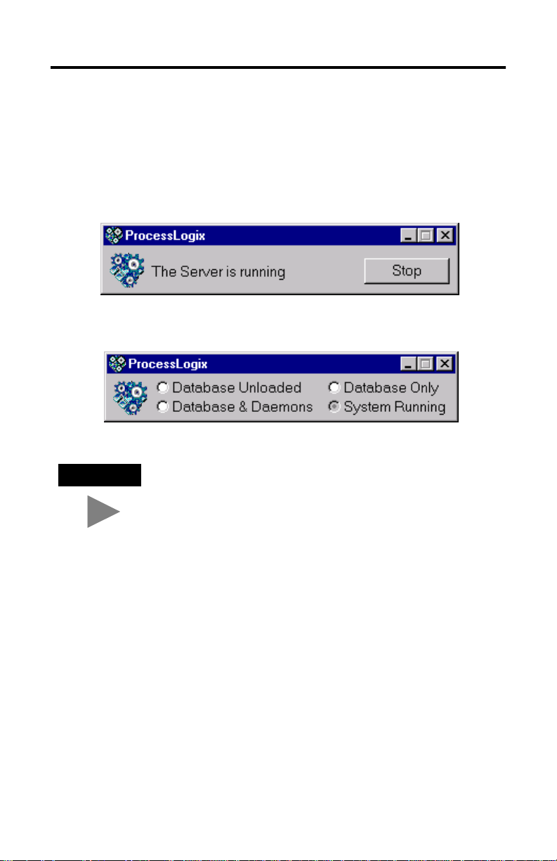
Starting the ProcessLogix Server
The ProcessLogix Server program is the operating system for the ProcessLogix
Server. To start the Server:
1. Click Start⇒Programs⇒ProcessLogix Server⇒Start-Stop ProcessLogix Server
to call up the ProcessLogix Server dialog box. Check that the Server is
running.
OR
To display the “Full Mode” version of the ProcessLogix Server
dialog box, click the icon to the left of ProcessLogix in the
title bar and click Advanced
now appear in front of the Full Mode selection to show that it
is active.
2. If the Server is running, close the dialog box. If the Server is not running:
a. With the Full Mode version of the dialog box active, click the System
Running option.
b. Click Yes to confirm the action and wait for the Server to change its state.
c. Close the ProcessLogix Server dialog box.
Publication 1757-QS040A-EN-P - October 2001
⇒Full Mode. A checkmark will
Page 7
Getting Started with ProcessLogix R400.0 7
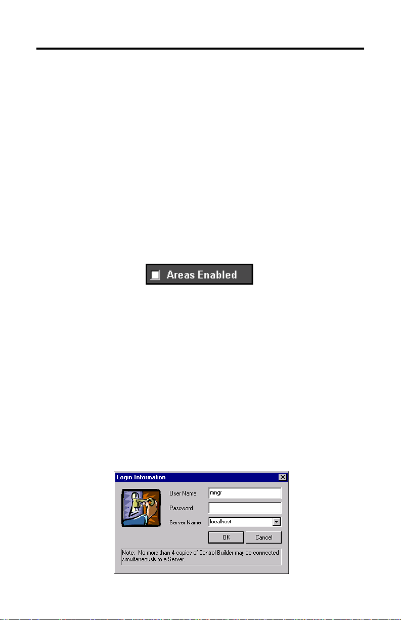
Turning Off Areas
Areas are portions of a process you wish to control. This Quick Start assumes that
Areas are turned off. To turn off areas:
1. Click Start⇒Programs⇒ProcessLogix Server⇒Station.
2. Select Configure⇒Areas⇒Areas.
3. Access manager mode.
a. Click Oper in the bottom right of the screen.
b. In the Station Logon dialog box, type mngr.
c. Click OK.
Oper changes to Mngr.
4. To disable areas, uncheck the Areas Enabled check box.
5. Exit Station.
Starting Control Builder
Control Builder software is an application you use to develop CMs (Control
Modules) and SCMs (Sequential Control Modules). The CMs and SCMs are
downloaded to the 1757-PLX52 Control Processor Module. CMs contain Function
Blocks, and together with SCMs you can tell the 1757-PLX52 how to control your
process.
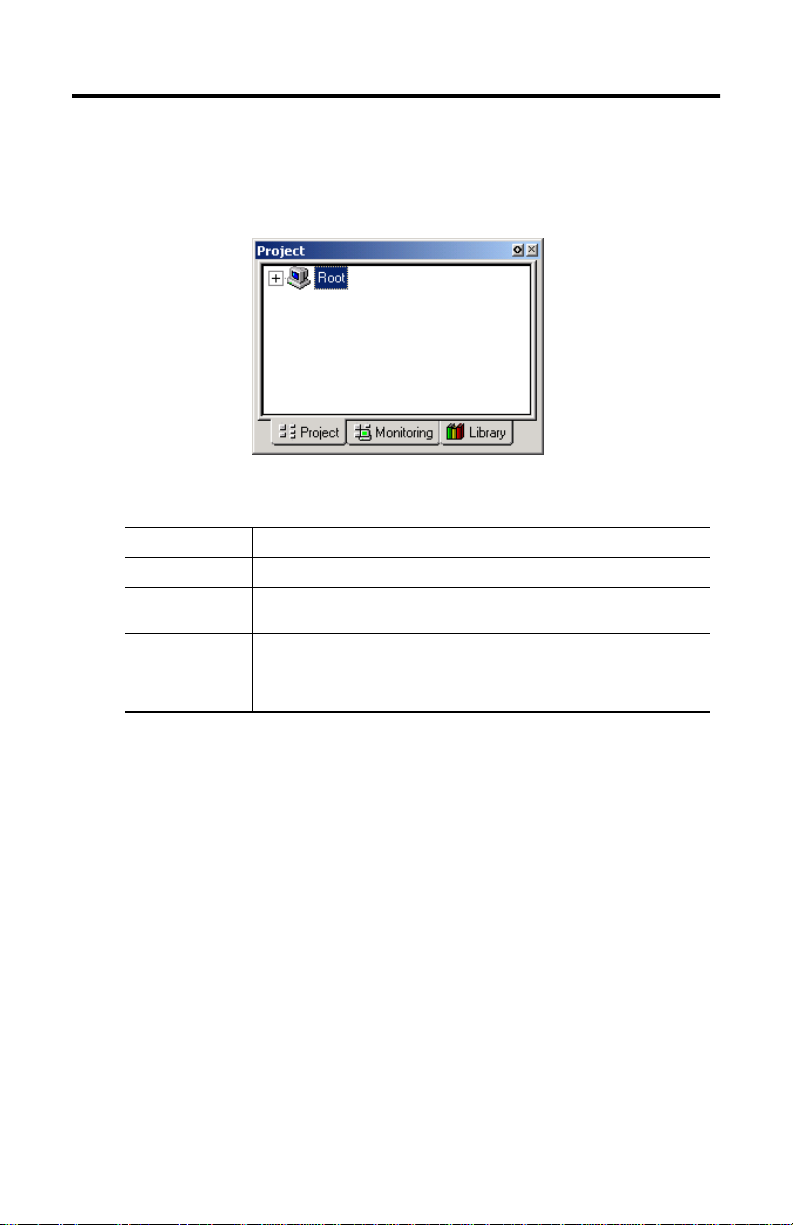
To start Control Builder:
1. Click Start⇒Programs⇒ProcessLogix Engineering Tools⇒Control Builder.
A Login Information window appears.
Publication 1757-QS040A-EN-P - October 2001
Page 8
8 Getting Started with ProcessLogix R400.0
2. Enter mngr (lowercase) for your User Name and mngr1 (lowercase) for your
Password, and click OK.
3. Control Builder starts up displaying the Project tab:
The available tabs are described in the following table:
this tab: shows you:
Project the offline copy of your project
Monitoring the loaded or currently running copy of the application executing on the
Library
1757-PLX52 Control Processor Module
available I/O modules (IOM)
•
available function blocks for use in Control Modules
•
available function blocks for use in Sequential Control Modules
•
available control component libraries (CCLs)
•
Once you have opened Control Builder, you can begin configuring your hardware.
Creating a Controller
The first step in configuring your hardware is to create a controller.
1. In Control Builder, select File⇒New⇒Controllers⇒CPM-Control Processor
Module. You see the CPM Parameters dialog box (CPM = PLX52):
Publication 1757-QS040A-EN-P - October 2001
Page 9

Getting Started with ProcessLogix R400.0 9
2. In the CPM Parameters dialog box, select the following:
IMPORTANT
in this field: enter/select:
CPM Name CPM0101
Network Type ControlNet
Driver Name AB_PCIC-1
Supervisory MAC Address 01 (for the ControlNet 1756-CNB card)
Supervisory Slot Number 00
CPM Slot Number 01
CEE Name CEE0101
Be careful to enter the CPM Parameters correctly. You will not be
able to change them after they are entered.
Publication 1757-QS040A-EN-P - October 2001
Page 10

10 Getting Started with ProcessLogix R400.0
TIP
TIP
3. Click OK to close the CPM Parameters dialog box.
4. To see your newly configured CPM and CEE, click the Project tab.
To see the CPM and CEE, you may need to expand the Root
branch of your tree by clicking the small “+” sign to the left of
the word Root.
The CEE is listed under the CPM and is connected directly to it. This tells
you that the CEE is assigned to the CPM.
5. Load the CPM and the CEE:
a. In the project tab, click CPM0101.
b. From the Toolbar Menu, click the green down arrow.
The Load dialog box appears.
c. Verify the selected object is CPM0101, and click OK.
d. Click the Monitoring tab to verify that the loaded CPM and CEE can be
seen.
Loading the CPM also loads the corresponding CEE. To see the
CPM and CEE in the Monitoring tab, you may need to expand
the Root branch of your tree by clicking the small “+” sign to
the left of the word Root. The CPM and the CEE should
appear blue.
Publication 1757-QS040A-EN-P - October 2001
Page 11

Getting Started with ProcessLogix R400.0 11
Configuring I/O Modules
Once you have created a controller, the next step is to configure the I/O modules
you will use in your system.
Before you can configure a module, you must add it from the library to your
project:
1. Click the Library tab.
2. Click the
3. Create the I/O module blocks by dragging and dropping these modules, in
the order listed below, from the Library tab to the Project tab Root (on the
second tree display). You are prompted to change the I/O module name as
they are added.
Catalog Number Name
1756-IF6I LabAI
1756-OF6CI or
1756-OF6VI
1756-IB16I LabDI
1756-OB16I LabDO
+ to the left of the IO icon to see a list of available modules.
LabAO
Publication 1757-QS040A-EN-P - October 2001
Page 12

12 Getting Started with ProcessLogix R400.0
TIP
In the Project tab, you can see the modules displayed under
Root.
Configuring analog input modules
To configure an analog input module:
1. Double-click the IOM with the name LabAI.
This brings up the window for the 6-channel isolated analog input module
(1756-IF6I).
2. On the IOM Configuration window, select the Main tab and enter the
following parameters:
in this field: enter:
IOM Slot Number the slot number containing this module (remember
Remote I/O Chassis Mac Address 0 (this indicates module in same rack as controller)
ControlNet Module Slot Number 0
that chassis numbering begins with 0)
3. Select the Channel Configuration tab and enter the following parameters for
all channels:
in this field: select:
Input Range 0V to 10V
Notch Filter 60Hz
4. Click OK.
Publication 1757-QS040A-EN-P - October 2001
Page 13

Getting Started with ProcessLogix R400.0 13
Configuring analog output modules
To configure an analog output module:
1. Double-click the IOM named LabAO.
This brings up the window for the 6-channel isolated analog output module
(1756-OF6CI; current output, or 1756-OF6VI; voltage output).
2. On the IOM Configuration window, select the Main tab and enter the
following parameters:
in this field: enter:
IOM Slot Number the slot number containing this module
Remote I/O Chassis Mac Address 0
ControlNet Modulel Slot Number 0
3. Select the Channel Configuration tab and enter the following parameters for
all channels:
in this field: enter:
Shed to Safe Value unchecked
Calibration Bias 0
4. Click OK.
Configuring digital input modules
To configure a digital input module:
1. Double-click the IOM with the name LabDI.
This brings up the window for the 16-channel, 24V DC isolated analog input
module (1756-IB16I).
Publication 1757-QS040A-EN-P - October 2001
Page 14

14 Getting Started with ProcessLogix R400.0
2. On the IOM Configuration window, select the Main tab and enter the
following parameters:
in this field: enter:
IOM Slot Number the slot number containing this module
Remote I/O Chassis Mac Address 0
ControlNet Modulel Slot Number 0
3. Select the Module Configuration tab.
4. In the Filter Times fields, select 1MSDELAY for all channels.
5. Click OK.
Configuring digital output modules
To configure a digital output module:
1. Double-click the IOM named LabDO.
This brings up the window for the 16-channel, 24V DC isolated discrete
output module (1756-OB16I).
2. On the IOM Configuration window, select the Main tab and enter the
following parameters:
in this field: enter:
IOM Slot Number the slot number containing this module
Remote I/O Chassis Mac Address 0
ControlNet Modulel Slot Number 0
3. Click OK.
Publication 1757-QS040A-EN-P - October 2001
Page 15

Getting Started with ProcessLogix R400.0 15
Assigning Modules to a Controller Execution Environment
Once you have configured I/O modules, you must assign them to the controller
execution environment (CEE). To assign modules to the CEE:
1. From Control Builder, select Tools⇒Assign.
You see the Controller Assignments window:
2. Click the IOMs tab in the Available Modules area.
3. To select all four modules, click the first module, hold down the Shift Key,
and click the last module.
4. Select CEE0101 from the Select a CEE/Link box.
5. Click Assign.
After a few seconds, the IOMs are displayed in the Assigned Modules list
box. This indicates that the I/O modules you just assigned are being used by
the selected CPM/CEE, and cannot be assigned to other CPMs.
6. After the modules are assigned, click close.
Publication 1757-QS040A-EN-P - October 2001
Page 16

16 Getting Started with ProcessLogix R400.0
TIP
ATTENTION
!
TIP
7. Locate the Labx I/O modules in the CEE0101 folder of the Project tab.
To locate the IOMs, you may need to expand the CEE and I/O
branches of the tree in the Project tab.
8. Load the IOMs by doing the following:
a. Select all of the IOMs in the I/O list area.
Load only the I/O modules that physically exist in the chassis.
b. Click the green down arrow (load) in the toolbar.
The Load dialog box appears.
c. Verify that the I/O modules are all checked and click OK.
The assigned I/O modules appear under their CPM in the Monitor and
Project tabs.
In Monitoring tab:
Publication 1757-QS040A-EN-P - October 2001
Double-click the I/O module in the Monitoring tab to see
connection status on the Module Configuration tab.
• blue indicates “inactive,”
• green indicates “active and OK.”
• red indicates “active and failed.”
Page 17

Getting Started with ProcessLogix R400.0 17
Creating a PID Loop
The next step is to create a Control Module to control a process. In this example,
we create a PID loop.
Creating the Control Module
To create the Control Module:
1. Click File⇒New⇒Control Module. You see a blank window for the Control
Module in the center of your screen.
2. Rename the Control Module:
a. Double-click anywhere in the CM Window. You see the Parameter
window.
b. In the Name field, enter FIC102.
3. Select the Server tab and enter the following parameters:
in this field: enter (not case-sensitive):
Point Detail Page sysdtlpida.dsp
Group Detail Page sysgrppida.dsp
4. Click OK to close the Parameter window.
5. Save your changes by clicking File⇒Save. Notice that the new Control
Module name appears in the Project Tab.
6. Close the Control Module FIC102.
Publication 1757-QS040A-EN-P - October 2001
Page 18

18 Getting Started with ProcessLogix R400.0
Assigning the Control Module to the Controller Execution Environment
To assign the Control Module for the PID loop to the CEE:
1. From Control Builder, select Tools⇒Assign.
2. On the Controller Assignments window, click the CMs/SCMs tab in the in the
Available Modules box.
3. Select FIC102 from the Available Modules box.
4. Select the CEE0101 from the CEE/Link box and click Assign.
The FIC102 module is displayed in the Assigned Modules box.
5. Close the Controller Assignments window.
Building the PID Loop
To develop the PID loop:
1. In the Project tab, open the Control Module by double-clicking FIC102.
2. Click the Library tab.
3. Display the available function blocks by clicking the + to the left of the
appropriate library in the tree display.
4. Click the desired block, then drag and drop it onto the your diagram.
5. Rename the block by double-clicking the block to bring up the Parameters
window.
6. Add the following function blocks to the Control Module:
In this library: Choose this function block: Rename:
DATAACQ DATAACQ DACA
IOCHANNEL AICHANNEL AI00
IOCHANNEL AOCHANNEL AO00
REGCTL PID PIDA
UTILITY NUMERIC NUMERIC
Publication 1757-QS040A-EN-P - October 2001
Page 19

Wire the blocks
TIP
Getting Started with ProcessLogix R400.0 19
IMPORTANT
Adjust your blocks to look similar to the window below.
The Numeric block you created enables you to simulate a control
loop. For this loop to work properly, do not wire the
AICHANNEL block.
1. Double-click the source wire. The cursor changes to a “+”.
2. Click the destination wire.
For additional wire segments as you draw
your wire, click the left mouse button.
Publication 1757-QS040A-EN-P - October 2001
Page 20

20 Getting Started with ProcessLogix R400.0
Configure parameters
1. Double-click the NUMERIC block. You see the Numeric Parameters window.
2. Enter 10 in the Actual Value field.
3. Click OK.
4. Double-click the PID block. You see the PID Parameters window.
5. Click the Algorithm tab.
6. Enter these parameters:
in this field: enter:
T1 0.1
T1 High Limit 2
High Gain Limit 2
Overall Gain 0.5
7. Click OK.
8. Double-click the AICHANNEL block. You see the AICHANNEL Parameters
window.
9. Enter LabAI in the Module Name field.
10. Select Channel 0.
11. Click Assign Channel Block.
12. Click OK.
13. Double-click the AOCHANNEL block. You see the AOCHANNEL Parameters
window.
14. Enter LabAO in the Module Name field.
15. Select Channel 0.
16. Click Assign Channel Block.
17. Click OK.
Publication 1757-QS040A-EN-P - October 2001
Page 21

Getting Started with ProcessLogix R400.0 21
Enter Alarms
1. Double-click the DATACQ block to display the Parameters window.
2. Click the Alarms tab.
3. Enter these alarms:
IMPORTANT
4. Click OK.
5. Close the Control Module FIC102.
6. When prompted, click Yes to save changes.
You must enter the PV High alarm first to enable the PV High
High alarm.
type trip point priority severity
PV High 85 High 0
PV High High 95 Urgent 0
Downloading the Function Block Diagram to the 1757-PLX52 Control Processor Module
Use this method to download your function block diagram to the Control Processor
Module.
1. In the Project tab, click FIC102.
2. From the Toolbar Menu, click the green down arrow to download the
function block diagram.
3. Click OK to load the selected object to the CEE.
Publication 1757-QS040A-EN-P - October 2001
Page 22

22 Getting Started with ProcessLogix R400.0
Changing the Controller Execution Environment for the
1757-PLX52 Control Processor Module from Inactive to Active
To execute your program, you must change the CEE and CM from inactive to
active. Follow these steps to change the CEE, CM, and IOMs to active:
1. In the Monitoring tab, click CEE0101.
2. Select Operate⇒Activate⇒This CEE and its IOMs and CMs.
3. Click Yes to change the state of the selected objects. You see the CEE and
everything listed under it in the tree view under the Monitoring tab go solid
green.
Verifying Proper Operation
Follow these steps to verify that your PID loop operates properly:
1. In the Monitoring tab, double-click FIC102. The PID diagram opens.
2. On the PID block, look at the MODE parameter to ensure that it is set to
MAN (manual).
3. With the PID block in manual mode, double-click the OP parameter.
4. Set the OP Value in % to 80.
5. Click Yes when prompted to Change Online value and click OK.
6. On the PID block, double-click the MODE parameter and set it to AUTO
(automatic).
7. Click Yes when prompted to Change Online Value and click OK.
8. Double-click the setpoint wire (SP) and set the setpoint to 25.
9. Click Yes when prompted to Change Online Value and click OK.
Publication 1757-QS040A-EN-P - October 2001
Page 23

Getting Started with ProcessLogix R400.0 23
10. Verify that the PID OP output value (displayed near the wire) changes.
11. Change the NUMERIC.PV to 20, then 30.
12. Click Yes when prompted to Change Online Value and click OK.
Observe the OP output of the PID block for changes.
13. Close the diagram without saving your changes.
Viewing Pre-built Screens
To view the pre-built screens provided with the ProcessLogix system:
1. If the Station application program is not running, select Start⇒Programs⇒
ProcessLogix Server⇒Station.
2. Click the text box in the upper right corner of the screen (below the
toolbar).
to view the detail screen for the: do this:
Controller 1. Type
CEE 1. Type
PID loop 1. Type
I/O modules 1. Type the name of the I/O module in the box. [for
Alarms Click the red, blinking alarm indicator at the bottom
CPM0101
2. Press [F12].
CEE0101
2. Press [F12].
FIC102
2. Press [F12].
example, LabAI]
2. Press [F12].
of the screen, or click the Alarm icon in the toolbar
menu.
in the box.
in the box.
in the box.
Publication 1757-QS040A-EN-P - October 2001
Page 24

Allen-Bradley, ProcessLogix, and RSLinx are trademarks of Rockwell Automation
Windows 2000 is a registered trademark of Microsoft Corporation
Publication 1757-QS040A-EN-P - October 2001 PN 957555-53
Copyright © 2001 Rockwell Automation. All rights reserved. Printed in the U.S.A.
 Loading...