

Page 1
Installation Instructions
ProcessLogix Controller
Catalog Number 1757-PLX52
Topic Page
Important User Information 2
North American Hazardous Location Approval 3
Environment and Enclosure 4
Prevent Electrostatic Discharge 5
Before You Begin 6
Install the Battery 7
Install the 1757-PLX52 Controller 9
Uninstall the 1757-PLX52 Controller 10
Verify Network Connection 11
Specifications 12
Additional Resources 15
Publication 1757-IN901D-EN-P - May 2007
Page 2
2 ProcessLogix Controller
Important User Information
Solid state equipment has operational characteristics differing from those of electromechanical equipment.
Safety Guidelines for the Application, Installation and Maintenance of Solid State Controls (publication
SGI-1.1 available from your local Rockwell Automation sales office or online at
http://literature.rockwellautomation.com) describes some important differences between solid state
equipment and hard-wired electromechanical devices. Because of this difference, and also because of the
wide variety of uses for solid state equipment, all persons responsible for applying this equipment must
satisfy themselves that each intended application of this equipment is acceptable.
In no event will Rockwell Automation, Inc. be responsible or liable for indirect or consequential damages
resulting from the use or application of this equipment.
The examples and diagrams in this manual are included solely for illustrative purposes. Because of the many
variables and requirements associated with any particular installation, Rockwell Automation, Inc. cannot
assume responsibility or liability for actual use based on the examples and diagrams.
No patent liability is assumed by Rockwell Automation, Inc. with respect to use of information, circuits,
equipment, or software described in this manual.
Reproduction of the contents of this manual, in whole or in part, without written permission of Rockwell
Automation, Inc., is prohibited.
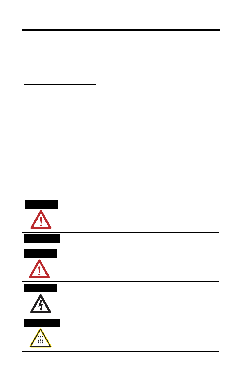
Throughout this manual, when necessary, we use notes to make you aware of safety considerations.
WARNING
IMPORTANT
ATTENTION
SHOCK HAZARD
BURN HAZARD
Identifies information about practices or circumstances that can cause an explosion in
a hazardous environment, which may lead to personal injury or death, property
damage, or economic loss.
Identifies information that is critical for successful application and understanding of
the product.
Identifies information about practices or circumstances that can lead to personal injury
or death, property damage, or economic loss. Attentions help you to identify a hazard,
avoid a hazard, and recognize the consequences.
Labels may be on or inside the equipment, for example, a drive or motor, to alert
people that dangerous voltage may be present.
Labels may be on or inside the equipment, for example, a drive or motor, to alert
people that surfaces may reach dangerous temperatures.
Publication 1757-IN901D-EN-P - May 2007
Page 3
ProcessLogix Controller 3
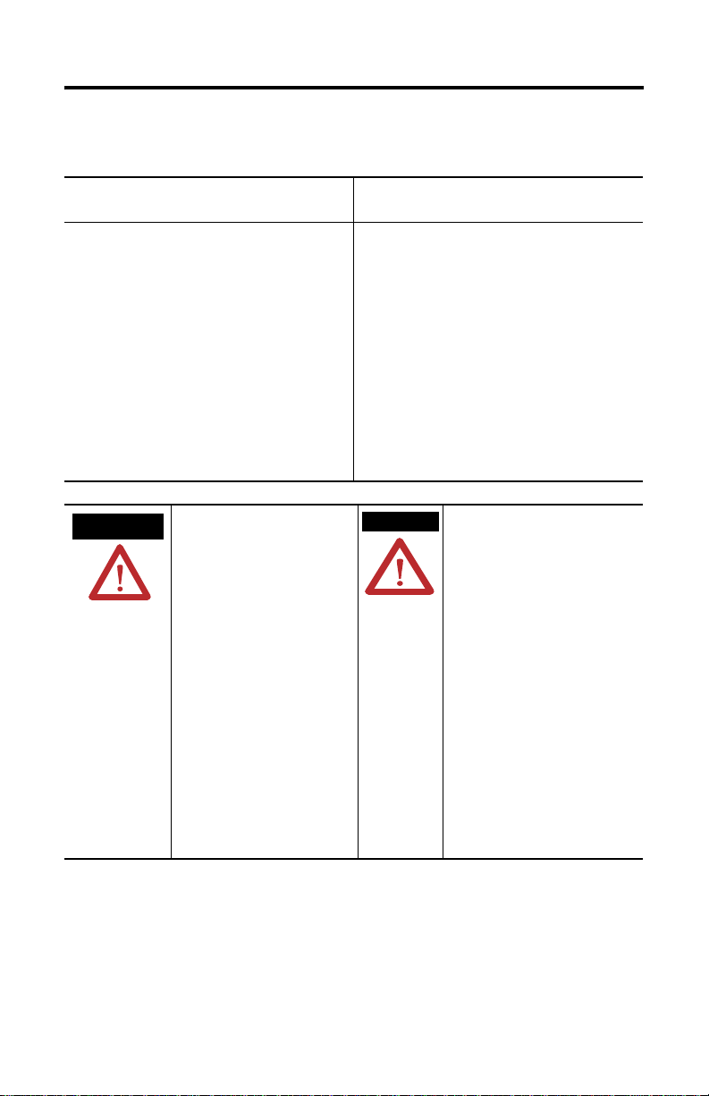
North American Hazardous Location Approval
The following Information applies when operating
this equipment in hazardous locations:
Products marked "CL I, DIV 2, GP A, B, C, D" are
suitable for use in Class I Division 2 Groups A, B, C,
D, Hazardous Locations and nonhazardous locations
only. Each product is supplied with markings on the
rating nameplate indicating the hazardous location
temperature code. When combining products within
a system, the most adverse temperature code (lowest
"T" number) may be used to help determine the
overall temperature code of the system.
Combinations of equipment in your system are
subject to investigation by the local Authority Having
Jurisdiction at the time of installation.
WARNING
EXPLOSION HAZARD
Do not disconnect equipment unless
power has been removed or the area
is known to be nonhazardous.
Do not disconnect connections to this
equipment unless power has been
removed or the area is known to be
nonhazardous. Secure any external
connections that mate to this
equipment by using screws, sliding
latches, threaded connectors, or othe r
means provided with this product.
Substitution of components may
impair suitability for Class I, Division
2.
If this product contains batteries, th ey
must only be changed in an area
known to be nonhazardous.
Informations sur l'utilisation de cet équipement en
environnements dangereux:
Les produits marqués "CL I, DIV 2, GP A, B, C, D" ne
conviennent qu'à une utilisation en environnements
de Classe I Division 2 Groupes A, B, C, D dangereux
et non dangereux. Chaque produit est livré avec des
marquages sur sa plaque d'identification qui
indiquent le code de température pour les
environnements dangereux. Lorsque plusieurs
produits sont combinés dans un système, le code de
température le plus défavorable (code de
température le plus faible) peut être utilisé pour
déterminer le code de température global du
système. Les combinaisons d'équipements dans le
système sont sujettes à inspection par les autorités
locales qualifiées au moment de l'installation.
AVERTISSEMENT
RISQUE D'EXPLOSION
Couper le courant ou s'assurer que
l'environnement est classé non
dangereux avant de débrancher
l'équipement.
Couper le courant ou s'assurer que
l'environnement est classé non
dangereux avant de débrancher les
connecteurs. Fixer tous les connecteurs
externes reliés à cet équipement à l'aide
de vis, loquets coulissants, connecteurs
filetés ou autres moyens fournis avec ce
produit.
La substitution de composants peut
rendre cet équipement inadapté à une
utilisation en environnement de Classe I,
Division 2.
S'assurer que l'environnement est classé
non dangereux avant de changer les
piles.
Publication 1757-IN901D-EN-P - May 2007
Page 4

4 ProcessLogix Controller
N
Environment and Enclosure
ATTENTIO
This equipment is intended for use in a Pollution Degree 2 industrial
environment, in overvoltage Category II applications (as defined in IEC
publication 60664-1), at altitudes up to 2000 meters (6562 ft) without derating.
This equipment is considered Group 1, Class A industrial equipment according to
IEC/CISPR Publication 11. Without appropriate precautions, there may be
potential difficulties ensuring electromagnetic compatibility in other
environments due to conducted as well as radiated disturbance.
This equipment is supplied as open-type equipment. It must be mounted within
an enclosure that is suitably designed for those specific environmental
conditions that will be present and appropriately designed to prevent personal
injury resulting from accessibility to live parts. The enclosure must have suitable
flame-retardant properties to prevent or minimize the spread of flam e, complying
with a flame spread rating of 5VA, V2, V1, V0 (or equivalent) if non-metallic. The
interior of the enclosure must be accessible only by the u se of a tool. Subseque nt
sections of this publication may contain additional information regarding specific
enclosure type ratings that are required to comply with certain prod uct safety
certifications.
In addition to this publication, see:
• For additional installation requirements, Industrial Automation Wiring and Grounding
Guidelines, publication 1770-4.1.
• NEMA Standards, publication 250, and IEC publication 60529, as applicable, for
explanations of the degrees of protection provided by different types of enclosure.
Publication 1757-IN901D-EN-P - May 2007
Page 5

Prevent Electrostatic Discharge
N
ProcessLogix Controller 5
ATTENTIO
This equipment is sensitive to electrostatic discharge, which can cause internal
damage and affect normal operatio n. Follow these guidelines when you handle
this equipment:
• Touch a grounded object to discharge potential static.
• Wear an approved grounding wriststrap.
• Do not touch connectors or pins on component boards.
• Do not touch circuit components inside the equipment.
• Use a static-safe workstation, if available.
• Store the equipment in appropriate static-safe packaging when not in use.
Publication 1757-IN901D-EN-P - May 2007
Page 6

6 ProcessLogix Controller
Before You Begin
To communicate with the 1757-PLX52 controller, your Server must have the following:
• An operating PCIC or Ethernet card
• A device driver for the network card
• A valid network address to communicate with network devices
• RSLinx software properly configured
• RSLinx drivers
Each network device must also have a unique network address.
Refer to the Installation and Upgrade Guide that was shipped with your ProcessLogix
software or the device installation instructions for more information.
Publication 1757-IN901D-EN-P - May 2007
Page 7

ProcessLogix Controller 7
Install the Battery
The battery is disconnected during shipping to conserve power. Follow this procedure to
install the battery.
WARNING
1. Open the front door of the 1757-PLX52 controller.
2. Locate the battery connector (a small, white plug at the end of a pair of red and black
twisted wires).
Battery holder
When you connect or disconnect the battery an electrical arc can occur. This
could cause an explosion in hazardous location installations. Be sure that
power is removed or the area is nonhazardous before proceeding.
For Safety information on the handling of lithium batteries, including handling
and disposal of leaking batteries, see Guidelines for Handling Lithium
Batteries, publication AG 5-4.
Battery lead terminal
3. Turn the plug so that the wires enter the plug from the right.
Publication 1757-IN901D-EN-P - May 2007
42788
Page 8

8 ProcessLogix Controller
4. Slide the plug over the two-prong male plug in the battery compartment.
5. Insert the end of the battery away from the lead wire into the recessed area in the
controller. Be certain that the black retaining tab (located next to the battery lead
terminal) clicks and secures the battery in its holder.
6. Close the controller front door.
Publication 1757-IN901D-EN-P - May 2007
Page 9

Install the 1757-PLX52 Controller
ProcessLogix Controller 9
WARNING
If you insert or remove the controller while backplane power is on, an electrical
arc can occur. This could cause an explosion in hazardous location installations.
Be sure that power is removed or the area is nonhazardous before proceeding.
The 1757-PLX52 controller can be installed into any two consecutive slots of the chassis. The
default location is slots 1 and 2.
1. Align the controller circuit board with the top and bottom guides in the chassis.
Top chassis guide alignment
Bottom chassis
guide alignment
31241
2. Slide the controller into the chassis in the appropriate slot. Make sure the controller
properly connects to the chassis backplane.
The controller is fully installed when it is flush with the other installed modules, and
the locking clips click into place.
Publication 1757-IN901D-EN-P - May 2007
Page 10

10 ProcessLogix Controller
Uninstall the 1757-PLX52 Controller
WARNING
To remove the controller complete the following procedure.
1. Turn off chassis power.
2. Push down on the locking clips at the top right and bottom left of the controller.
If you insert or remove the controller while backplane power is on, an electrical
arc can occur. This could cause an explosion in hazardous location installations.
Be sure that power is removed or the area is nonhazardous before proceeding.
3. Slide the controller out of the chassis.
Publication 1757-IN901D-EN-P - May 2007
31242
Page 11

ProcessLogix Controller 11
Verify Network Connection
To verify that the controller is communicating over the network, complete the following
steps.
1. In RSLinx, select Communications > RSWho.
The RSWho window opens.
2. Expand the ControlNet or Ethernet node and verify that the 1757-PLX52 controller
is listed in the backplane.
IMPORTANT
The 1757-PLX52 controller is supplied with only the boot code installed. You
must update the controller firmware before you can use it in your system.
Refer to the Installation and Upgrade Guide that was shipped with your
ProcessLogix software for more information.
Publication 1757-IN901D-EN-P - May 2007
Page 12

12 ProcessLogix Controller
Specifications
ProcessLogix Controller - 1757-PLX52
Attribute Value
Intrinsically safe No
Temp. rate of change ≤ 1 °C/min (≤ 33.8 °F/min)
Corrosives G2 std, G3 option (ISA S71.04)
Emissions CISPR 11:
Group 1, Class A
ESD immunity IEC 61000-4-2:
Radiated RF immunity IEC 61000-4-3:
Power requirements 24V dc @ 5 mA
Controller battery backup time
Lithium battery
(standard, built in)
Battery Extension Module,
1757-BEM
Removal/Insertion under power
(RIUP)
4 kV indirect contact discharges
10V/m with 1 kHz sine-wave 80%AM from 80…2000 MHz
5.1V dc @ 1.6 A
3.3V dc @ 1.3 A
1.2V dc @ 7 mA
144 hours (non-rechargeable) - 6 days:
Replacement Battery: 1757-PLXBAT
Lithium battery is disconnected during shipment.
120 hours (rechargeable) - 5 days
Spare Battery: 1757-BEMS
Permitted when equipment is installed in ordinary, non-hazardous,
locations (I/O modules reload automatically).
Not permitted when equipment is installed in a Class I, Division 2,
Hazardous (Classified) Location.
Publication 1757-IN901D-EN-P - May 2007
Page 13

ProcessLogix Controller 13
Environmental Specifications
Attribute Value
Temperature, operating IEC 60068-2-1 (Test Ad, Operating Cold),
IEC 60068-2-2 (Test Bd, Operating Dry Heat),
IEC 60068-2-14 (Test Nb, Operating Thermal Shock):
0… 60 °C (32… 140 °F)
Temperature, non-operating IEC 60068-2-1 (Test Ab, Unpackaged Non-operating Cold),
IEC 60068-2-2 (Test Bb, Unpackaged Non-operating Dry Heat),
IEC 60068-2-14 (Test Na, Unpackaged Non-operating Thermal Shock):
-40… 85 °C (-40… 185 °F)
Barometric pressure Altitude, -300… 2000 m
Relative humidity IEC 60068-2-30 (Test Db, Unpackaged Damp Heat):
5… 95% non-condensing
Vibration IEC 60068-2-6 (Test Fc, Operating):
0.5 g @ 10… 60 Hz
Shock, operating IEC 60068-2-27 (Test Ea, Unpackaged Shock): 5 g
Shock, non-operating IEC 60068-2-27 (Test Ea, Unpackaged Shock): 20 g
Enclosure requi red Yes
Enclosure type rating None (open-style)
North American temperature code T4A
(1)
The maximum relative humidity specification applies up to 40 °C (140 °F). Above 40°C (140 °F) the RH specification is
de-rated to 55% to maintain constant moisture content.
(1)
Publication 1757-IN901D-EN-P - May 2007
Page 14

14 ProcessLogix Controller
Certifications
Certification
(when product is marked)
(1)
Value
C-Tick Australian Radiocommunications Act, compliant with:
AS/NZS CISPR 11; Industrial Emissions"
CE European Union 89/336/EEC EMC Directive, compliant with:
EN 50082-2; Industrial Immunity
EN 61326; Meas./Control/Lab., Industrial Requirements
EN 61000-6-2; Industrial Immunity
EN 61000-6-4; Industrial Emissions
EN 61131-2; Programmable Controllers (Clause 8, Zone A & B)
CSA CSA Certified Process Control Equipment for Class I, Division 2 Group
A,B,C,D Hazardous Locations. See CSA File LR18656C.
FM FM Approved Equipment for use in Class I Division 2 Group A,B,C,D
Hazardous Locations
UL UL Listed Industrial Control Equipment. See UL File E65584.
(1)
See the Product Certification link at www.ab.com for Declarations o f Confo rmity, Certificates, and other cer tificat ion det ails.
Publication 1757-IN901D-EN-P - May 2007
Page 15

ProcessLogix Controller 15
Additional Resources
For instructions, specifications and applications for the power supply, chassis, I/O modules,
network cabling, and other related hardware and software, refer to the documentation that
was shipped with the hardware and software.
You can view or download publications at http://literature.rockwellautomation.com
order paper copies of technical documentation, contact your local Rockwell Automation
distributor or sales representative.
. To
Publication 1757-IN901D-EN-P - May 2007
Page 16

Rockwell Automation Support
Rockwell Automation provides technical information on the Web to assist you in using its
products. At http://support.rockwellautomation.com
knowledge base of FAQs, technical and application notes, sample code and links to software
service packs, and a MySupport feature that you can customize to make the best use of these
tools.
For an additional level of technical phone support for installation, configuration, and
troubleshooting, we offer TechConnect Support programs. For more information, contact
your local distributor or Rockwell Automation representative, or visit
http://support.rockwellautomation.com
.
Installation Assistance
If you experience a problem with a hardware module within the first 24 hours of installation,
please review the information that's contained in this manual. You can also contact a special
Customer Support number for initial help in getting your module up and running.
, you can find technical manuals, a
United States 1.440.646.3223
Outside United
States
Monday – Friday, 8am – 5pm EST
Please contact your local Rockwell Auto mat ion representative for any
technical support issues.
New Product Satisfaction Return
Rockwell tests all of its products to ensure that they are fully operational when shipped from
the manufacturing facility. However, if your product is not functioning, it may need to be
returned.
United States Contact your distributor. Y ou must pro vide a Customer Supp ort case number
Outside United
States
Rockwell Automation, Allen-Bradley, RSLinx, ProcessLogix, and TechConnect are trademarks of Rockwell Automation.
Trademarks not belonging to Rockwell Automation are property of their respective companies.
(see phone number above to obtain one) to your distributor in order to
complete the return process.
Please contact your local Rockwell Auto mation representative for return
procedure.
Publication 1757-IN901D-EN-P - May 2007 PN 953157-63
Supersedes Publication 1757-IN901C-EN-P - June 2001 Copyright © 2007 Rockwell Automation, Inc. All rights reserved. Printed in the U.S.A.
 Loading...