

Page 1

Installation Instructions
ProcessLogix Pulse Input Module
Catalog no. 1757-PIM
This document tells you how to install the 1757-PIM (Pulse Input Module) into the
ProcessLogix™ System. For more specific information regarding the placement of
the 1757-PIM in non-redundant and redundant configurations, refer to the
ProcessLogix System Planning Guide in Knowledge Builder.
What is the Pulse Input Module?
The 1757-PIM (Pulse Input Module) is a new addition to the ProcessLogix Rack
I/O family.
The 1757-PIM is a single-wide I/O module that serves as the interface board
between the ProcessLogix controller and field transducers that provide pulse inputs.
Typically the 1757-PIM might be used to accept pulse inputs from:
• tachometers, to determine required speeds of rotation for motors, fans and
pumps
• flowmeters, to determine totalized process flows such as inputs to batch
dosing operations
The 1757-PIM provides up to eight input channels and two output channels. Each
of the eight channels has a 32-bit counter to perform pulse counting and frequency
calculation for signals up to 100 KHz. Six of the eight channels also have a second
32-bit timer counter for pulse period and pulse width measurements. The
remaining channels provide pulse counting and frequency calculations and have
associated outputs that can be used for fast cut-off applications. The 1757-PIM
provides channel-to-channel and terminal-to-backplane isolation.
The 1757-PIM uses the standard 36-pin terminal block and interfaces directly to
single-ended devices. The threshold level for each channel is software configurable
and selections are either LOW (approx. 3.25V typical) or HIGH (approx. 8.80V
typical) for a high-level voltage level. The 1757-PIM interfaces directly to 5 to 24V
signal values.
Publication 1757-IN900A-US-P - February 2000
Page 2

2 ProcessLogix Pulse Input Module
ATTENTION
!
Important User Information
Because of the variety of uses for the products described in this publication, those
responsible for the application and use of this control equipment must satisfy
themselves that all necessary steps have been taken to assure that each application
and use meets all performance and safety requirements, including any applicable
laws, regulations, codes and standards.
The illustrations, charts, sample programs and layout examples shown in this guide
are intended solely for purposes of example. Since there are many variables and
requirements associated with any particular installation, Allen-Bradley does not
assume responsibility or liability (to include intellectual property liability) for actual
use based upon the examples shown in this publication.
Allen-Bradley publication SGI-1.1, Safety Guidelines for the Application, Installation
and Maintenance of Solid-State Control (available from your local Allen-Bradley
office), describes some important differences between solid-state equipment and
electromechanical devices that should be taken into consideration when applying
products such as those described in this publication.
Reproduction of the contents of this copyrighted publication, in whole or part,
without written permission of Rockwell Automation, is prohibited.
Throughout this manual we use notes to make you aware of safety considerations.
Identifies information about practices or circumstances that can
lead to personal injury or death, property damage or economic
loss
Attention statements help you to:
• identify a hazard
• avoid a hazard
• recognize the consequences
IMPORTANT
Allen-Bradley is a trademark of Rockwell Automation
Publication 1757-IN900A-US-P - February 2000
Identifies information that is critical for successful application
and understanding of the product.
Page 3
ProcessLogix Pulse Input Module 3
ATTENTION
!
Installing the Module
Follow the procedure below to install the module.
Making Field Wiring Connections
Refer to the following pinout/wiring diagram to wire the module.
This input module permits the field-side input device (switch)
to be located on either the hot or neutral side of the source,
unless the module’s shorting bar has been installed. In this
case, the input device must be installed on the hot side of the
source.
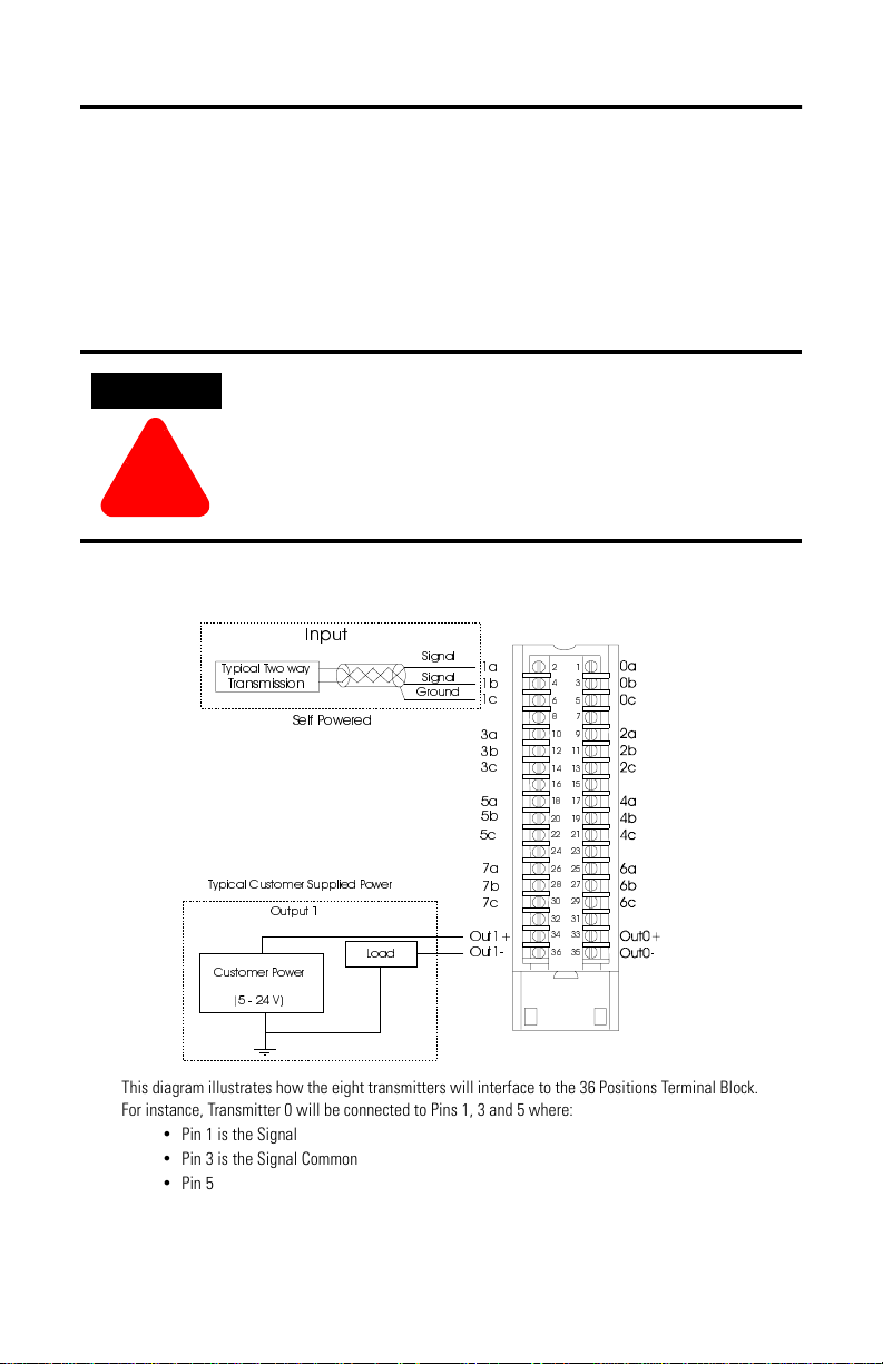
Figure 1 Pinouts and Wiring Example
,QSXW
7\SLFDO7ZRZD\
7UDQVPLVVLRQ
6HOI3 RZHUHG
7\SLFDO&XVWRPHU6XSSOLHG3RZHU
2XWSXW
&XVWRPHU3RZHU
9
/RDG
6LJQDO
6LJQDO
*URXQG
D
E
F
D
E
F
D
E
F
D
E
F
2XW
2XW
This diagram illustrates how the eight transmitters will interface to the 36 Positions Terminal Block.
For instance, Transmitter 0 will be connected to Pins 1, 3 and 5 where:
Pin 1 is the Signal
•
Pin 3 is the Signal Common
•
Pin 5 is the Chassis Ground Shield Connection
•
The Output Channel 0 will connect to Pins 33 and 35 and Output Channel 1 will connect to Pins 34
and 36.
Publication 1757-IN900A-US-P - February 2000
Page 4
4 ProcessLogix Pulse Input Module
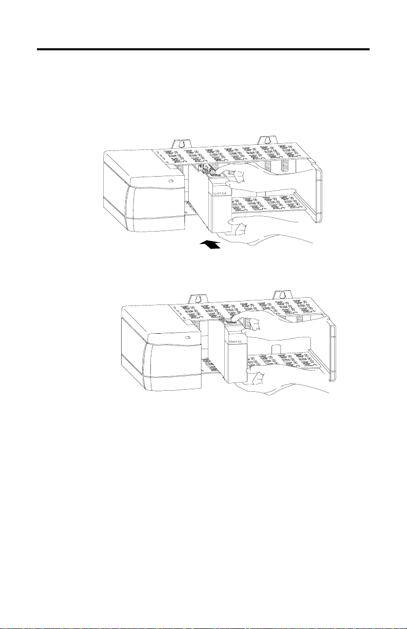
Installing the Module in the Chassis
Position the module at any slot in the chassis except for slot 0.
Align the module’s circuit board with the top and bottom chassis guides.
Slide the module into the chassis until the module tabs click into position
Configuring the Module
You can customize the 1757-PIM by changing its name, description, slot location,
MAC address, as well as Module, Channel, Status/Data and Server configuration
parameters. Perform the following steps to customize the 1757-PIM.
Publication 1757-IN900A-US-P - February 2000
Page 5
ProcessLogix Pulse Input Module 5
Access Control Builder.
Add a new 1757-PIM from the library.
a. Open the Library and Project tree views.
b. In the Library tree view, click on the 1757-PIM icon and drag it to the
Project tree window.
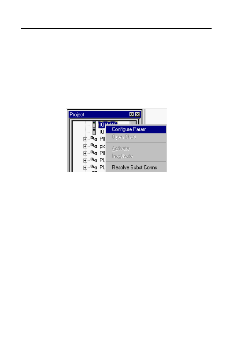
Right-click on the desired IOM instance on the Project tree window.
Click on Configure Param. You see the Main, Module Configuration, Channel
Configuration, Status/Data and Server Parameters configuration tabs.
Under the Main tab (see figure below), enter a Module Name that is more
meaningful to you than its default IOMxxx (xxx represents a pre-assigned
number).
Publication 1757-IN900A-US-P - February 2000
Page 6

6 ProcessLogix Pulse Input Module
TIP
If desired, enter a Module Description to explain the function of the
1757-PIM (such as Test Strategy PIM). This is not a required field.
Enter appropriate values for IOM Slot Number, Remote IO Chassis MAC
Address and CNI Slot Number. If necessary, press F1 to access on-line help
for assistance during this step.
Use the following procedures to configure parameters on the remaining tabs
for the 1757-PIM, or click OK to accept only the changes made so far and
return to the Project tree.
Under the Module Configuration tab (see figure below), enter desired values
for configuration parameters. If necessary, press F1 to access on-line help for
assistance during this step.
The only available choice is whether or not to select the
Alarming Enabled checkbox. Once the module has been
loaded and activated, additional parameters (such as Execution
State) may be configured on the Monitoring Tree window.
Publication 1757-IN900A-US-P - February 2000
Page 7

ProcessLogix Pulse Input Module 7
Continue with the following procedures to configure parameters on the
remaining tabs for the 1757-PIM, or click OK to accept only the changes
made so far and return to the Project tree.
Under the Channel Configuration tab (see figure below), enter desired
values for configuration parameters. If necessary, press F1 to access on-line
help for assistance during this step.
Publication 1757-IN900A-US-P - February 2000
Page 8

8 ProcessLogix Pulse Input Module
Continue with the following procedures to configure parameters on the
remaining tabs for the 1757-PIM, or click OK to accept only the changes
made so far and return to the Project tree.
Under the Status/Data tab (see figure below), enter desired values for
configuration parameters. If necessary, press F1 to access on-line help for
assistance during this step.
Publication 1757-IN900A-US-P - February 2000
Page 9

ProcessLogix Pulse Input Module 9
Continue with the following procedures to configure parameters on the
remaining tabs for the 1757-PIM, or click OK to accept only the changes
made so far and return to the Project tree.
Under the Server Parameters tab (see figure below), enter the appropriate
information such as filenames for desired display templates (Point Detail
Page, Group Detail Page and Associated Displays), along with values for
appropriate parameters such as for Control Level, Control Area, and EU
HI/EU LO parameters. If necessary, press F1 to access on-line help for
assistance during this step.
Publication 1757-IN900A-US-P - February 2000
Page 10

10 ProcessLogix Pulse Input Module
Click OK on the configuration form to accept all configuration selections
made on each configuration tab and to return to the Project tree.
For Technical Assistance
For technical assistance, call Rockwell Automation Technical Support at(440)
646-6800.
Publication 1757-IN900A-US-P - February 2000
Page 11

Specifications
Parameter Specification
Input Channel Characteristics:
Number of Input Channels:
Input Configuration:
Input Voltage Range:
Input Required Current:
Hysteresis Minimum:
Frequency Range:
Isolation Voltage:
Accumulated Value Size:
Up to 8 input channels are capable of pulse counting
•
•
Single-ended
5 to 24 Vdc selectable between high input range (logic high threshold at
approx. 8.80V typical and low input range (logic high threshold at
approx. 3.25V typical)
12.5mA Max. (for high input range 6mA typical; for low input range 2mA
typical)
Low Input Range: 550mV, minimum
High Input Range: 900mV
100KHz Maximum
Terminal Block to Backplane: 1500V
Channel-to-Channel: 1500V
32 bits
ProcessLogix Pulse Input Module 11
6 channels are also capable of frequency and pulse width
calculation
2 channels have associated outputs and frequency calculation
Output Channels:
Isolation Voltage:
Environmental Conditions:
Operating/Storage
Temperature:
Transportation Band
Temperature:
Relative Humidity:
Up to 2 output channels are available
Output current is capable of 500mA with an external power supply
Terminal Block to Backplane: 1500V
Channel-to-Channel: 1500V
°C (32 to 140°F) with no fans
0 to 60
-40 to 85°C (-40 to 185°F)
5 to 95% non-condensing up to 40
5 to 55% non-condensing above 40
(1)
°C (104°F)
°C (104°F)
Publication 1757-IN900A-US-P - February 2000
Page 12

12 ProcessLogix Pulse Input Module
Parameter Specification
Vibration:
Operating/Storage Vibration
(3 axes):
•
•
•
Frequency: 10-60Hz
Acceleration: 0.5g Max.
Displacement: 0.1 inches (0.254cm)
Transportation Band Vibration
(3 axes):
Mechanical Shock:
Operating/Storage Shock:
Transportation Shock:
Barometric Pressure:
Operating/Storage Altitude:
Transportation Band Altitude:
Corrosives:
With enclosure:
Enclosure external temperature
limits:
CE Mark Standard
Compliance:
Electromagnetic Interference: 15V/m, SAMA Standard PMC 33.3-1978
Electrostatic Discharge: Same as CE Mark, IEC801-2, plus 15kV to enclosure, controller surfaces
Frequency: 0-60Hz
•
Acceleration: 1g Max.
•
Displacement: 0.1 inches (0.254cm)
•
Acceleration: 5g Max.
•
Duration: 30ms Max.
•
Acceleration: 20g Max.
•
Duration: 30ms Max.
•
-300 to +3000m (-984 to 9843 ft.)
Any
G2 standard, G3 option (ISA S71.04)
TBD
Yes
Class 2 or same as CE Mark
(whichever is more severe)
and min. 10kV to all field wires.
Surge Protection: Same as CE Mark, IEC801-4 and 5 or IEEE SWC 472-1989 (whichever is
more severe)
Publication 1757-IN900A-US-P - February 2000
Page 13

Parameter Specification
Certifications:
FM, CSA
Unclassified Areas
FM Class 1, Div. 2
Yes
Mounting and interfacing
Mounting – maintenance requires a hot work permit
ProcessLogix Pulse Input Module 13
C-tick
(1)
A value of 70°C (158°F) is the maximum “component ambient” temperature when the air temperature below
the chassis is 0° to 60°C (32 to 140°F).
Yes
European Communities (EC) Directive Compliance
If this product has the CE mark it is approved for installation within the European
Union and EEA regions. It has been designed and tested to meet the following
directives.
EMC Directive
This product is tested to meet the Council Directive 89/336/EC Electromagnetic
Compatibility (EMC) by applying the following standards, in whole or in part,
documented in a technical construction file:
• EN 50081-2 EMC — Generic Emission Standard, Part 2 — Industrial
Environment
• EN 50082-2 EMC — Generic Immunity Standard, Part 2 — Industrial
Environment
This product is intended for use in an industrial environment.
Low Voltage Directive
This product is tested to meet Council Directive 73/23/EEC Low Voltage, by
applying the safety requirements of EN 61131-2 Programmable Controllers, Part 2 Equipment Requirements and Tests. For specific information required by EN
61131-2, see the appropriate sections in this publication, as well as the
Allen-Bradley publication Industrial Automation Wiring and Grounding Guidelines
For Noise Immunity, publication 1770-4.1.
This equipment is classified as open equipment and must be mounted in an
enclosure during operation to provide safety protection.
Publication 1757-IN900A-US-P - February 2000
Page 14

14 ProcessLogix Pulse Input Module
ATTENTION
!
CSA Hazardous Location Approval
CSA certifies products for general use as well as for use in hazardous locations. Actual CSA certification is indicated by the product
label as shown below, and not by statements in any user documentation.
Example of the CSA certification product label:
CL I, DIV 2
GP A,B,C,D
TEMP
To comply with CSA certification for use in hazardous locations, the following information becomes a part of the product literature
for this CSA-certified industrial constrol product.
This equipment is suitable for use in Class I, Division 2, Groups A, B, C, D, or non-hazardous locations only.
•
The products having the appropriate CSA markings (that is, Class I, Division 2, Groups A, B, C, D) are
•
certified for use in other equipment where the suitability of combination (that is, application or use) is
determined by the CSA or the local inspection office having jurisdiction.
IMPORTANT
Due to the modular nature of a programmable control system, the
product with the highest temperature rating determines the overall
temperature code rating of a programmable control system in a Class
I, Division 2, location. The temperature code rating is marked on the
product label as shown.
Temperature code rating
The following warnings apply to products having CSA certification for use in hazardous locations.
CL I, DIV 2
GP A,B,C,D
TEMP
Look for temperature code
rating here.
Explosion hazard!
Substitution of components may impair suitability for Class I, Division 2.
•
Do not replace components unless power has been switched off or the area is
•
known to be non-hazardous.
Do not disconnect equipment unless power has been switched off or the area is
•
known to be non-hazardous.
Do not disconnect connectors unless power has been switched off or the area is
•
known to be non-hazardous. Secure any user-supplied connectors that mate to
external circuits on this equipment by using screws, sliding latches, threaded
connectors, or other means such that any connection can withstand a 15 Newton
(3.4 lb.) separating force applied for a minimum of one minute.
If the Product contains batteries, they must only be changed in an area known to be
•
non-hazardous.
CSA logo is a registered trademark of the Canadian Standards Association.
Publication 1757-IN900A-US-P - February 2000
Page 15

ProcessLogix Pulse Input Module 15
ATTENTION
!
Approbation d’utilisation dans des environnements dangereux par la CSA
La CSA certifie des produits pour une utilisation générale aussi bien que pour une utilisation en environnements dangereux. La
certification CSA en vigueur est indiquée par l'étiquette produit et non par des indications dans la documentation utilisateur.
Exemple d'étiquette de certification d'un produit par la CSA
CL I, DIV 2
GP A,B,C,D
TEMP
Pour satisfaire à la certification CSA en environnements dangereux, les informations suivantes font partie intégrante de la
documentation des produits de commande industrielle certifiés.
Cet équipement ne convient qu’à une utilisation dans
•
des environnements de Classe 1, Division 2,
Groupes A, B, C, D ou non dangereux.
Les produits portant le marquage CSA approprié (c'est-à-dire Classe 1, Division 2, Groupes A, B, C, D)
•
sont certifiés pour une utilisation avec d'autres équipements, les combinaisons d’applications et
d’utilisation étant déterminées par la CSA ou le bureau local d'inspection.
IMPORTANT
De par la nature modulaire des systèmes de commande
programmables, le produit ayant le code de température le plus élevé
détermine le code de température global du système dans un
environnement de Classe I, Division 2. Le code de température est
indiqué sur l'étiquette produit.
&RGHGHWHPSpUDWXUH
Les avertissements suivants s’appliquent aux produits ayant la certification CSA pour une utilisation dans des environnements
dangereux.
CL I, DIV 2
GP A,B,C,D
TEMP
Le code de température
est indiqué ici.
Risque d'explosion
La substitution de composants peut rendre ce matériel inadapté à une utilisation en
•
environnement de
Classe 1, Division 2.
Couper le courant ou s'assurer que l’environnement est classé non dangereux avant
•
de remplacer des composants.
Couper le courant ou s’assurer que l’environnement est classé non dangereux avant
•
de débrancher l'équipement.
Couper le courant ou s'assurer que l’environnement est classé non dangereux avant
•
de débrancher les connecteurs. Fixer tous les connecteurs fournis par l'utilisateur
pour se brancher aux circuits externes de cet appareil à l 'aide de vis, loquets
coulissants, connecteurs filetés ou autres, de sorte que les connexions résistent à
une force de séparation de 15 Newtons (1,5 kg - 3,4 lb.) appliquée pendant au moins
une minute.
S'assurer que l'environnement est classé non dangereux avant de changer les piles.
•
Publication 1757-IN900A-US-P - February 2000
Page 16

Notes:
Publication 1757-IN900A-US-P - February 2000 PN 957280-08
© 2000 Rockwell International Corporation. Printed in the U.S.A.
 Loading...