

Rockwell Automation SLC 500, 1746-P1, 1746-P2, 1746-P3, 1746-P4 Installation Instructions Manual
...Page 1

MANUFACTURER DATA SHEET
Power Supply
Manufacturer:
Allen-Bradley/Rockwell
Model Number:
1746-P1
See www.geomartin.com for additional PDF datasheets
Martin Part Number:
E-014624-01
VendorPartNumber:
AB # 1746-P1, Power Supply
PDF File: Doc_000005_Cover.pdf
Page 2

This page is intentio n allyleft blank
Page 3
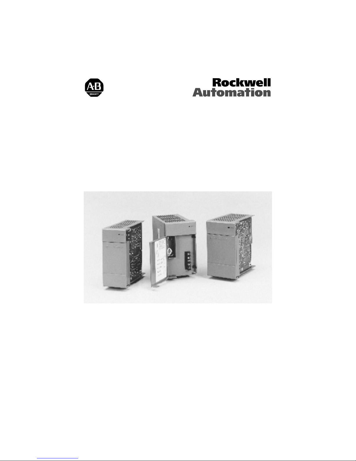
SLC 500™ Power Supplies
(Catalog Numbers 1746-P1, 1746-P2, 1746-P3,
1746-P4, 1746-P5, 1746-P6, and 1746-P7)
Installation Instructions
Inside… page
Overview . . . . . . . . . . . . . . . . . . . . . . . . . . . . . . . . . . . . . . . . . . . . . . . . . . . . . . . . . . 1
Genéralités . . . . . . . . . . . . . . . . . . . . . . . . . . . . . . . . . . . . . . . . . . . . . . . . . . . . . . . . 13
Deutscher Abschnitt . . . . . . . . . . . . . . . . . . . . . . . . . . . . . . . . . . . . . . . . . . . . . . . . . 25
Istruzioni per l’installazione. . . . . . . . . . . . . . . . . . . . . . . . . . . . . . . . . . . . . . . . . . . . 37
Instrucciones de instalación . . . . . . . . . . . . . . . . . . . . . . . . . . . . . . . . . . . . . . . . . . . 49
Publication 1746-IN004A-ML-P
Page 4

2
SLC 500™ Power Supplies
Important User Information
Because of t he vari ety of us es for the pro duc ts desc ribed in t his p ublica ti on, tho se
responsible for the application and use of this control equipm ent must satisfy
themselves that all necessary steps have been taken to assure that each
application and us e meets all performance and safety requi rements, including any
applicabl e laws, regulations, code s and standards.
The illustrations, charts, sample programs and layout examples shown in this
guide are inte nded solely for purposes of example . Since there are many
variables and re quirements associate d with any particular installation, Alle nBradley does not as sume responsibility or liabilit y (to include intellec tual
property li ability) for actual use based upon the examples shown in this
publication.
Allen-Bradle y publication SGI-1.1,
Installation, and Maintenanc e of Solid-State Control
Allen-Bradle y office), describes some important differences between solid-state
equipment and ele ctrom echan ical devices tha t shoul d be taken into cons iderat ion
when applying products such as those described in this publication.
Reproduction of the contents of this copyrighted publication, in whole or in part ,
without written permission of Allen-B radley Company, Inc., is prohibited.
Throughout these installation instructions we use not es to make you aware of
safety considerations:
A TTE NTION:
circumstances that can lead to personal injury or death, property
!
Attention statements help you to:
• identify a hazard
• avoid the hazard
• recognize the consequences
Important:
damage or economic loss.
Identifies information that is critical for success f ul application and
understanding of the product.
Safety Guideli nes for the Applicati on,
(available from your local
Identifies information about practices or
Publication 1746-IN004A-ML-P
Page 5
English Section
SLC 500™ Power Supplies
(Catalog Numbers 1746-P1, 1746-P2, 1746-P3,
1746-P4, 1746-P5, 1746-P6, and 1746-P7)
Overview
Install your po wer supply using these ins tallation instructions. The only tools
you require are Flat head (1/8”) and Phillips hea d (1/4”, #2) screwdrivers.
ATTENTION:
circuits or semiconductors if you touch backplane connector pins.
Follow the se guidelines when you handle the power supplies.
!
• Touch a grounded object to discharge static potential.
• Do not touch the backplane connector or connector pins.
• Do not touch circuit compo nents inside the power supply .
• If availab le , u se a sta ti c-safe wor k sta ti o n .
• When not in use, keep the powe r supplies in their static-shield
packaging.
Electrostatic discharge can damage integrated
1746-IN004A-ML-P
Page 6

4
SLC 500™ Power Supplies
Hazardous Location Considerations
This equipment is suitable for use in Clas s I, Division 2, Groups A, B, C, D or
non-hazardous loc ations only. The following WARNING statement applie s to use
in hazardou s lo catio n s .
WAR NING:
• Substitution of component s ma y impair suit ability for Clas s I,
Division 2.
• Do not replace components or disconnect equipment unless
power has been switched off or the area is known to be nonhazardous.
• Do not connect or discon nec t components unless power has
been switched off or the area is known to be non-hazardous.
• All wiring must comply with N.E.C. article 501-4(b).
EXPLOSION HAZARD
Environnements Dangereux
Cet équipement est conçu pour être util isé dans des environnements de Classe I,
Division 2, Groupes A, B, C, D ou non dangereux. La mise en garde suivante
s’applique à une utilisation dans des environnements dangereux.
AVERTISSEMENT:
• La substitution de composants peut rendre cet équipement
impropre à une utilisation en en vironnement de Clas se I ,
Division 2.
• Ne pas remplacer de composants ou déconnecter
l'équipement sans s'être assuré que l'alimentation est coupée.
DANGER D’EXPLOSION
1746-IN004A-ML-P
• Ne pas connecter ou déconnecter des composants sans s'être
assuré que l'alimentation est coupée.
Page 7

SLC 500™ Power Supplies
Install the Chassis Interconnect Cable (Optional)
To connect up to three SLC 500™ ch assis together, install the chassis
interconnect ca ble before installing the power supply
.
SLC 500 chassis/A
For more information, see the
SLC 500 Modular Style
Installation and Operation
(publication 1747-6.2).
Manual
Power S uppl y Inst allation
1. Align the circuit board of the power suppl y with the card guides on the left
side of the chassis
.
5
2. Slide the power supply in until it is flush with the chassis. Then fasten the
power suppl y to the chassis
.
Use these screws to fasten the
power supply to the chassis.
1746-IN004A-ML-P
Page 8

6
SLC 500™ Power Supplies
Power S uppl y Wiring
1. Place the input voltage jumper to match the input voltage. (This does not
apply to the 17 46-P3, -P5, -P6, an d -P7 po wer s uppl ies, whic h do no t hav e a
jumper.)
ATTENTION:
Set the input jumper before applying power.
Hazardous voltage is present on exposed pins when power is
!
Jumper Selection
applied; contact with the pin may cause injury to personnel.
Fuse
100/120 Volts
200/240 Volts
Catalog Number
1746-P1 & -P2
Jumper Selection
85-132V ac
170-265V ac
Catalog Num b er
1746-P4
2. Connect the groun d sc rew of the power supply to the nearest ground or
ground bus. Use a #14 AWG wire and keep the leads as short as poss ible.
The 1746-P4 is shown below.
Refer to page 6 for special wiring
considerations for the 1746-P3.
1746-IN004A-ML-P
CHASSIS GROUND
Nearest Ground Bus
Page 9

3. Connect incoming power.
SLC 500™ Power Supplies
7
!
Catalog Number
1746-P1 & P2
Incoming
Power
Catalog Number
1746-P4
P4
Jumper
Selection
P4
Incoming
Power
ATTENTION:
Turn off incoming powe r before connecting
wires; failure to do so could cause injury to personnel and/or
equipment.
Catalog Numbe r
1746-P3
120/240V ac
VAC NEUT
CHASSIS GROUND
85–132V ac
JUMPER
170–265V ac
L1 85–132/170– 265
L2 NEUTRAL
CHASSIS GROUND
Incoming
Power
Catalog Numbe r
1746-P5
Incoming
Power
Catalog Number
1746-P6
Incoming
Power
+ 24V dc
DC NEUT
CHASSIS GROUND
+125V dc
DC NEUT
CHASSIS GROUNDCHASSIS GROUND
+48V dc
DC NEUT
CHASSIS GROUNDCHASSIS GROUND
ATTENTION:
voltage surges when s witching inductive loads such as motors,
motor starters, so lenoids, and relays. To avoid damage to your SLC
!
500 power suppl y in these ap plica tio ns, it is str ongl y recco mmended
than an isolation transformer be used to isol ate the power supply
from harmful voltage surges.
Catalog Number
1746-P7
Incoming
Power
+ 12/24V dc
DC NEUT
CHASSIS GROUND
Your SLC 500 power supply can be damaged by
1746-IN004A-ML-P
Page 10

8
SLC 500™ Power Supplies
1746-P3 Wiring Considerations
The information below describes special wiring considerations for the 1746-P3.
!
External DC Power Sourc e
Earth Ground
Important:
ATTENTION:
Any voltage applied to the 1746-P3 DC NEUT
terminal will be present at the SLC logic ground and the proc essor
DH-485 port. To prevent unwanted potent ials across the logic
ground of the controller and/or damage to the SLC chassis, the DC
NEUTRAL of the exte rnal DC power sourc e must be either isolated
from the SLC cha ssis ground or connected to earth ground as shown
in the following illustr ation.
SLC 500 Chassis
SLC Logic Ground
+24V dc
DC Neut
Chassis
Ground
Door
•
A jumper wire is
recommended between
the DC NEUT and
Chassis Gro und of the
external power s our ce.
1746-P3
+24V dc
DC Neut
Processor
DH±485
Port
Earth
Ground
SLC 500 Series A chassis (1746-A4, -A7, -A10, and -A13)
manufactured
November 1992 have a resistor between the
before
logic ground and chass is ground as the drawing on the following
page illustrates. This resistor could be damaged if the wiring
recommendation des cribed within the attention box above is not
followed. See the figure on the following page for the location of
the resistor. SLC 500 Series A chassis (1746-A4, -A7, -A10, and
-A13) with a manufacture date of November 1992 or late r do not
have this resistor. SLC 500 Series B chassis have a 1MΩ resistor
that limits the current between logic ground and chassis ground.
1746-IN004A-ML-P
Page 11

SLC 500™ Power Supplies
9
1746-P3
Processor
SLC 500 Chassis
Door
DH±485
Not Used
Port
Not Used
+24V dc
DC Neut
Chassis
Ground
Resistor
•
•
SLC Logic
Chassis
Earth
Ground
4.
(Optional)
For the 17 46-P1, -P 2,-P4 , -P5 and - P6 po wer suppli es, us e PWR
OUT +24V dc and PWR OUT COM te rmina ls to po wer 24V dc sens ors and
loads. The terminals on the 1746-P1, 1746-P2, 1746-P5 and 1746-P6
provide an is olat ed, no nfused 200 mA, 24V d c po wer supply. The termina ls
on the 1746-P4 provide an isolated, nonfused 1A, 24V dc power supply.
(The 1746-P3 and -P7 power supplies do not provide for an ext ernal power
source.)
Catalog Number
1746-P1, P2, P5 & P6
PWR OUT +24V dc
PWR OUT COM
User PowerUser Po we r
Catalog Numbe r
1746-P4
PWR OUT +24V dc
PWR OUT COMMON
1746-IN004A-ML-P
Page 12

10
SLC 500™ Power Supplies
SLC 500 Operation with 24V dc User Power Overcurrent Condition
Catalog No. SLC Operation Recovery Procedure
1746-P1 Series A
(made in Japan)
1746-P1 Series A
(made in Malaysiacurrent production)
1746-P2 Series A, B P/S shutdown, CPU Fault Reload user program
1746-P2 Series C 24V dc user shutdown, CPU continues Correct overcurrent condition
1746-P4 Series A P/S shutdown, CPU Fault Reload user program
1746-P5 Series A 24V dc user shutdown, CPU continues Correct overcurrent condition
1746-P6 Series A 24V dc user shutdown, CPU continues Correct overcurrent condition
P/S shutdown, CPU Fault Reload user program
24V dc user shutdown, CPU continues Correct overcurrent condition
ATTENTION:
C, 1746-P5 Series A, and 1746-P 6 Series A to aviod unex pected
!
5. Remove the protecti ve label.
operation due to 24V dc user power shutdown, monitor the 24V
dc user output with a 24V dc input channel.
For 1746-P1 (mad e in Mal aysia), 1746-P 2 Series
1746-IN004A-ML-P
Page 13

SLC 500™ Power Supplies
11
Power Supply Undervoltage Operation
SLC 500 controll ers c ontinue to op erate (hold-up) fo r a short period o f ti me if t he
input voltage to the power supply drops below the recommended operating
voltage range. The controller continues to scan the user program and control I/O
during th is time. CPU hold-up for each power supply is shown on pages 9 and 10 .
SLC 500 controllers turn OFF (stop scanning and disa ble outputs) if input
voltage to the power supply is remo ved or drops below the r ecommended
operating rang e for a per iod exceeding the CPU hold -up time. The controller
resumes o per ation automatically when the input v o ltage is restored to normal.
If the input voltage to the 1746-P7 power supply falls into a range of 4 to 9V for
a period ex ceeding the CPU hold- up time, the contr oller turns OFF and will not
turn back ON until:
• input volt age is increased to 11V dc.
1746-IN004A-ML-P
Page 14

12
SLC 500™ Power Supplies
General Specifications (Power Supplies P1, P2, P3, and P4)
See page 10 for general specifications on the P5, P6, and P7 power supplies.
Description:
P1 P2 P3 P4
Line Voltage
Typical Line Power
Reqmnt.
Maximum Inrush
Current
Internal Current
Capacity
Fuse Protection
24V dc User Power
Current Capacity
24V dc User Power
Volt. Range
Ambient Operating
Temperature
6
Isolation
CPU Hold-up Time
85-132/170-265V ac
47-63 Hz
135 VA 180 VA 90 VA 240 VA
20A 45A
2A at 5V dc
0.46A at 24V dc
1746-F1 or
2
equivalent
3
200 mA
18-30V dc 20.4-27.6V dc
0°C to +60°C (+32°F to +140°F)
Current capacity is derated 5% above +55°C.
1800V ac RMS for 1 s None
8
20 ms (full load) 3000 ms (no load)
UL listed
Certification
C-UL or CSA certified (as indicated by product or packaging markings)
CE compliant for all applicable directives
Hazardous
Environment Cert.
1. Th e combination of all output power (5 volt backplan e, 24 volt back plane, and 24 volt user source)
cannot exceed 70 watts.
2. Pow er su pply fuse is intended to guard against fire hazard due to short-cir cuit con dit ions . This fuse may
not protect the supply from miswiring or excessive transient in the power line.
3. Equivalent fuses: 250V-3A fuse, nagasawa ULCS-61ML-3, or BUSSMAN AGC 3
4. Equiv alent fuse: 250V-3A fuse, SANO SOC SD4, or BUS SM AN AGC 3
5. Equivalent fuse : 125V-3A fuse, Nagasawa ULCS-61ML-5, or BUSSMAN AGC 5
6. Isolation is between input terminals and backplane.
7. No isolation between input terminals and backplane. However, dielectric withstand between input
terminals and chassis ground terminal is 600V ac RMS for 1 s.
8. CP U hold -up time is for 0V unless specif ied. Hold- up tim e is dep endent on power supply loading.
Class I
Division 2
Specification: 1746-
5A at 5V dc
0.96A at 24V dc
1746-F2 or
equivalent
4
19.2-28.8V dc
3.6A at 5V dc
0.87A at 24V dc
1746-F3 or
equivalent
5
Not Applicable
7
5 ms (full load)
1000 ms (no load)
85-132/170-265V
ac 47-63 Hz
10.0A at 5V dc
2.88A at 24V dc
Fuse is soldered in
place.
1
1A
0°C to +60°C
(+32°F to +140°F)
no derating
2600V dc for 1 s
20 ms (full load)
3000 ms (no load)
1
1746-IN004A-ML-P
Page 15

SLC 500™ Power Supplies
General Specifications (continued)
Description:
P5 P6 P7
Line Voltage 90-146V dc 30-60V dc 10-30V dc
Typical Line
Power
85 VA 100 VA 12V dc input: 50 VA 24V dc input: 75 VA
Requirement
Maximum Inrush
Current
Internal Current
Capacity
Fuse Protection
20A 20A (required for turn-on)
5A at 5V dc
0.96A at 24V dc
2
Fuse is soldered in place.
24V dc User
Power Current
200 mA
Capacity
24V dc User
Power Voltage
18-30V dc
Range
Ambient
Operating Temp.
3
Isolation
CPU Hold-up
4
Time
0°C to +60°C (+32°F to +140°F)
Current capacity is derated 5% above +55°C.
1800V ac RMS for 1 s 600V ac RMS for 1 s
20 ms
(full load)
3000 ms (no
load)
5 ms
(full load)
1500 ms (no
load)
UL listed
Certification
C-UL or CSA certified (as indicated by product or packaging markings)
CE compliant for all applicable directives
Hazardous
Environment
Certification
1. See page 11. for information on power supply under voltage operation.
2. Pow er su pply fuse is intended to guard against fire hazard due to short-c ircu it condit ions . This fuse may
not protect the supply from miswiring or excessive transient in the power line.
3. Isolation is between input terminals and backplane.
4. CP U hold -up time is for 0V unless specif ied. Hold- up tim e is dep endent on power supply loading.
Class I
Division 2
Specification: 1746-
1
12V dc input:
2.0A at 5V dc
0.46A at 24V dc
24V dc input:
3.6A at 5V dc
0.87A at 24V dc
See P7 current capacity chart on page 11.
Not Applicable
12V dc input:
1.37 ms at 0V dc
(full load)
895 ms at 0V dc
(no load)
10 ms at 9V dc
(full load)
continuous at 9V dc
(no load)
24V dc input:
40 ms at 0V dc
(full load)
1860 ms at 0V dc
(no load)
790 ms at 11V dc
(full load)
continuous at 11V dc
(no load)
13
1746-IN004A-ML-P
Page 16

14
SLC 500™ Power Supplies
24V dc
Output Current
.87A
0.625A
0.46A
5V dc
Output Current
3.6A
2.64A
2.0A
10V dc 12.2V dc
15Vdc
Physical Dimensions
Controller: 1746-
P1 65 (2.56)
P2
P3
P4 110 (4.33) 145 (5.70)
P5
P7
Length:
mm (in.)
85 (3.35)
85 (3.35) 140 (5.70)P6
Depth:
mm (in.)
140 (5.70)
Input Voltage
19.2Vdc 30V dc
Height:
mm (in.)
140 (5.51)
1746-IN004A-ML-P
Page 17

Publication 1746-IN004 A-M L-P - Januar y 2000 40072-083-01 (A)
Supersede s Publ ic at ion 1746-5.1 - Oct 1999
2000 Rockwell International. All Rights Reserved. Printed in USA
Page 18

This page is intentio n allyleft blank
 Loading...