

Page 1

SLC 500
Thermocouple/mV
Analog Input
Module
1746-NT8
User Manual
Page 2
Important User Information
Solid state equipment has operational characteristics differing from those of
electromechanical equipment. Safety Guidelines for the Application,
Installation and Maintenance of Solid State Controls (Publication SGI-1.1
available from your local Rockwell Automation sales office or online at
http://www.ab.com/manuals/gi) describes some important differences
between solid state equipment and hard-wired electromechanical devices.
Because of this difference, and also because of the wide variety of uses for
solid state equipment, all persons responsible for applying this equipment
must satisfy themselves that each intended application of this equipment is
acceptable.
In no event will Rockwell Automation, Inc. be responsible or liable for
indirect or consequential damages resulting from the use or application of
this equipment.
The examples and diagrams in this manual are included solely for illustrative
purposes. Because of the many variables and requirements associated with
any particular installation, Rockwell Automation, Inc. cannot assume
responsibility or liability for actual use based on the examples and diagrams.
No patent liability is assumed by Rockwell Automation, Inc. with respect to
use of information, circuits, equipment, or software described in this manual.
Reproduction of the contents of this manual, in whole or in part, without
written permission of Rockwell Automation, Inc. is prohibited.
Throughout this manual, when necessary we use notes to make you aware of
safety considerations.
WARNING
IMPORTANT
ATTENTION
SHOCK HAZARD
BURN HAZARD
Identifies information about practices or circumstances
that can cause an explosion in a hazardous environment,
which may lead to personal injury or death, property
damage, or economic loss.
Identifies information that is critical for successful
application and understanding of the product.
Identifies information about practices or circumstances
that can lead to personal injury or death, property
damage, or economic loss. Attentions help you:
• identify a hazard
• avoid a hazard
• recognize the consequence
Labels may be located on or inside the equipment (e.g.,
drive or motor) to alert people that dangerous voltage may
be present.
Labels may be located on or inside the equipment (e.g.,
drive or motor) to alert people that surfaces may be
dangerous temperatures.
Page 3

Table of Contents
Preface
Module Overview
Installing And Wiring Your
Module
Who Should Use This Manual . . . . . . . . . . . . . . . . . . . . . . P-1
What This Manual Covers . . . . . . . . . . . . . . . . . . . . . . . . . P-1
Related Documentation . . . . . . . . . . . . . . . . . . . . . . . . . . P-2
Common Techniques Used in this Manual . . . . . . . . . . . . . P-2
Chapter 1
General Description . . . . . . . . . . . . . . . . . . . . . . . . . . . . . 1-1
Input Ranges . . . . . . . . . . . . . . . . . . . . . . . . . . . . . . . . 1-1
Hardware Features. . . . . . . . . . . . . . . . . . . . . . . . . . . . 1-2
Diagnostic LEDs. . . . . . . . . . . . . . . . . . . . . . . . . . . . . . 1-3
System Overview . . . . . . . . . . . . . . . . . . . . . . . . . . . . . . . 1-3
System Operation . . . . . . . . . . . . . . . . . . . . . . . . . . . . 1-4
Module Operation . . . . . . . . . . . . . . . . . . . . . . . . . . . . 1-5
Module Addressing . . . . . . . . . . . . . . . . . . . . . . . . . . . 1-5
Block Diagram. . . . . . . . . . . . . . . . . . . . . . . . . . . . . . . 1-6
Linear Millivolt Device Compatibility. . . . . . . . . . . . . . . 1-7
Chapter 2
Electrostatic Damage . . . . . . . . . . . . . . . . . . . . . . . . . . . . . 2-1
Power Requirements . . . . . . . . . . . . . . . . . . . . . . . . . . . . . 2-2
Considerations for a Modular System . . . . . . . . . . . . . . 2-2
Fixed I/O Chassis - I/O Module Compatibility . . . . . . . . 2-3
General Considerations . . . . . . . . . . . . . . . . . . . . . . . . . . . 2-4
Module Installation and Removal . . . . . . . . . . . . . . . . . . . . 2-5
Terminal Block Removal . . . . . . . . . . . . . . . . . . . . . . . 2-6
Wiring Your Module . . . . . . . . . . . . . . . . . . . . . . . . . . . . . 2-7
Preparing and Wiring the Cables . . . . . . . . . . . . . . . . . 2-9
Cold-Junction Compensation (CJC) . . . . . . . . . . . . . . . . 2-11
Chapter 3
Considerations Before Using Your
Module
i Publication 1746-UM022B-EN-P - January 2005
Module ID Code . . . . . . . . . . . . . . . . . . . . . . . . . . . . . . . . 3-1
Module Addressing . . . . . . . . . . . . . . . . . . . . . . . . . . . . . . 3-2
Output Image - Configuration Words . . . . . . . . . . . . . . 3-2
Input Image - Data Words and Status Words. . . . . . . . . 3-3
Channel Filter Frequency Selection . . . . . . . . . . . . . . . . . . 3-3
Channel Cut-Off Frequencyc . . . . . . . . . . . . . . . . . . . . 3-4
Channel Step Response . . . . . . . . . . . . . . . . . . . . . . . . 3-6
Update Time. . . . . . . . . . . . . . . . . . . . . . . . . . . . . . . . . . . 3-7
Update Time Calculation Example . . . . . . . . . . . . . . . . 3-8
Channel Turn-On, Turn-Off, and Reconfiguration Times . . . 3-8
Auto-calibration . . . . . . . . . . . . . . . . . . . . . . . . . . . . . . . . 3-8
Response to Slot Disabling . . . . . . . . . . . . . . . . . . . . . . . . 3-9
Input Response . . . . . . . . . . . . . . . . . . . . . . . . . . . . . . 3-9
Output Response . . . . . . . . . . . . . . . . . . . . . . . . . . . . . 3-9
Page 4

Table of Contents ii
Channel Configuration, Data, and
Status
Chapter 4
Channel Configuration . . . . . . . . . . . . . . . . . . . . . . . . . . . 4-1
Channel Configuration Procedure . . . . . . . . . . . . . . . . . . . 4-2
Select Channel Enable (Bit 0) . . . . . . . . . . . . . . . . . . . . 4-5
Select Input Types (Bits 1 through 4) . . . . . . . . . . . . . . 4-5
Select Data Format (Bits 5 and 6) . . . . . . . . . . . . . . . . . 4-5
Using Scaled-for-PID and Proportional Counts . . . . . . . 4-6
Effective Resolutions . . . . . . . . . . . . . . . . . . . . . . . . . . 4-6
Scaling Examples . . . . . . . . . . . . . . . . . . . . . . . . . . . . . . . 4-7
Select Open-Circuit State (Bits 7 and 8). . . . . . . . . . . . . 4-9
Select Temperature Units (Bit 9) . . . . . . . . . . . . . . . . . . 4-10
Select Channel Filter Frequency (Bits 10 and 11) . . . . . . 4-10
Unused Bits (Bits 12 through 14) . . . . . . . . . . . . . . . . . 4-11
Select Input Image Type (Bit 15) . . . . . . . . . . . . . . . . . 4-11
Channel Data/Status Word. . . . . . . . . . . . . . . . . . . . . . . . . 4-11
Channel Status Checking . . . . . . . . . . . . . . . . . . . . . . . . . . 4-12
Channel Status (Bit 0) . . . . . . . . . . . . . . . . . . . . . . . . . 4-14
Input Type Status (Bits 1 through 4) . . . . . . . . . . . . . . . 4-14
Data Format Type Status (Bits 5 and 6) . . . . . . . . . . . . . 4-14
Open-Circuit Type Status (Bits 7 and 8) . . . . . . . . . . . . 4-14
Temperature Units Type Status (Bit 9). . . . . . . . . . . . . . 4-14
Channel Filter Frequency (Bits 10 and 11). . . . . . . . . . . 4-15
Open-Circuit E. . . . . . . . . . . . . . . . . . . . . . . . . . . . . . . 4-15
Under-Range Error (Bit 13). . . . . . . . . . . . . . . . . . . . . . 4-15
Over-Range Error (Bit 14). . . . . . . . . . . . . . . . . . . . . . . 4-15
Channel Error (Bit 15) . . . . . . . . . . . . . . . . . . . . . . . . . 4-15
Programming Examples
Troubleshooting Your Module
Publication 1746-UM022B-EN-P - January 2005
Chapter 5
Procedure . . . . . . . . . . . . . . . . . . . . . . . . . . . . . . . . . . 5-2
Automatic Monitoring Thermocouples and CJC Sensors . . . 5-3
Verifying Configuration Changes . . . . . . . . . . . . . . . . . . . . 5-3
Interfacing to the PID Instruction. . . . . . . . . . . . . . . . . . . . 5-7
Monitoring Channel Status Bits . . . . . . . . . . . . . . . . . . . . . 5-8
Monitoring Channel Status Bits Example . . . . . . . . . . . . 5-9
PLC 5 Example with NT8 in Remote I/O Rack . . . . . . . . . . 5-13
SLC 500 Example with NT8 in Remote I/O Rack. . . . . . . . . 5-15
Chapter 6
Module and Channel Diagnostics. . . . . . . . . . . . . . . . . . . . 6-1
Module Diagnostics at Powerup . . . . . . . . . . . . . . . . . . 6-1
Channel Diagnostics. . . . . . . . . . . . . . . . . . . . . . . . . . . 6-1
LED Troubleshooting Tables. . . . . . . . . . . . . . . . . . . . . 6-3
Channel-status LEDs (Green) . . . . . . . . . . . . . . . . . . . . 6-4
Open-circuit Detection (Bit 12). . . . . . . . . . . . . . . . . . . 6-4
Page 5

Maintaining Your Module And
Safety Considerations
Module Specifications
Table of Contents iii
Out-of-Range Detection (Bit 13 for Under Range, Bit 14 for
Over Range) . . . . . . . . . . . . . . . . . . . . . . . . . . . . . . . . 6-4
Channel Error (Bit 15) . . . . . . . . . . . . . . . . . . . . . . . . . 6-5
Module Status LED (Green) . . . . . . . . . . . . . . . . . . . . . 6-5
Interpreting I/O Error Codes . . . . . . . . . . . . . . . . . . . . . . . 6-5
Chapter 7
Preventive Maintenance. . . . . . . . . . . . . . . . . . . . . . . . . . . 7-1
Safety Considerations . . . . . . . . . . . . . . . . . . . . . . . . . . . . 7-1
Appendix A
Electrical Specifications . . . . . . . . . . . . . . . . . . . . . . . . . . . A-1
Physical Specifications. . . . . . . . . . . . . . . . . . . . . . . . . . . . A-2
Environmental Specifications . . . . . . . . . . . . . . . . . . . . . . . A-2
Input Specifications. . . . . . . . . . . . . . . . . . . . . . . . . . . . . . A-3
Overall Accuracy . . . . . . . . . . . . . . . . . . . . . . . . . . . . . A-4
Millivolt. . . . . . . . . . . . . . . . . . . . . . . . . . . . . . . . . . . . A-4
Thermocouple . . . . . . . . . . . . . . . . . . . . . . . . . . . . . . . A-6
Using Grounded Junction,
Ungrounded Junction, and
Exposed Junction Thermocouples
Configuring the 1746-NT8 Module
with RSLogix 500
Appendix B
Thermocouple Types . . . . . . . . . . . . . . . . . . . . . . . . . . . . B-1
Grounded Junction . . . . . . . . . . . . . . . . . . . . . . . . . . . B-2
Ungrounded (Insulated) Junction . . . . . . . . . . . . . . . . . B-2
Exposed Junction. . . . . . . . . . . . . . . . . . . . . . . . . . . . . B-2
Isolation . . . . . . . . . . . . . . . . . . . . . . . . . . . . . . . . . . . . . . B-2
Grounded Junction . . . . . . . . . . . . . . . . . . . . . . . . . . . B-3
Exposed Junction Thermocouples. . . . . . . . . . . . . . . . . B-4
Appendix C
Glossary
Index
Publication 1746-UM022B-EN-P - January 2005
Page 6

Table of Contents iv
Publication 1746-UM022B-EN-P - January 2005
Page 7

Summary of Changes
The information below summarizes the changes to this manual since
the last printing. Updates to the manual include using RSLogix 500
instead of APS software.
To help you find new and updated information in this release of the
manual, we have included change bars as shown to the right of this
paragraph.
The table below lists the sections that document new features and
additional or updated information on existing features.
For this information: See
updated data table for initial programming page 5-2
added SLC 500 example with NT8 in
Remote I/O Rack
updated thermocouple graphs page A-8
configuring NT8 with RSLogix 500 page C-1
page 5-15
1 Publication 1746-UM022B-EN-P - January 2005
Page 8

Summary of Changes 2
Publication 1746-UM022B-EN-P - January 2005
Page 9

Preface
Read this preface to familiarize yourself with this user manual. This
preface covers:
• who should use this manual
• what this manual provides
• related documents
• common techniques used in this manual
Who Should Use This Manual
What This Manual Covers
Use this manual if you design, install, program, or maintain a control
system that uses SLC 500 controllers.
You should have a basic understanding of SLC 500 products. You
should also understand electronic process control and the ladder
program instructions required to generate the electronic signals that
control your application. If you do not, contact your local Rockwell
Automation representative for the proper training before using these
products.
This manual covers the 1746-NT8 thermocouple/millivolt analog input
module. It contains the information you need to install, wire, use, and
maintain these modules. It also provides diagnostic and
troubleshooting help should the need arise.
1 Publication 1746-UM022B-EN-P - January 2005
Page 10

Preface 2
Related Documentation
The following table lists several Rockwell Automation documents that
may help you as you use these products.
Publication Number
1746-SG001 SLC 500™ Systems Selection Guide
SGI-1.1 Safety Guidlines for the Application, Installation and
1770-4.1 Industrial Automation Wiringing and Grounding Guidelines
1747-UM011 SLC 500 Modular Modular Hardware Style User Manual
1747-6.21 Installation & Operation Manual for Fixed Hardware Style
1747-RM001 SLC 500 Instruction Set Reference Manual
AG-7.1 Allen-Bradley Industrial Automation Glossary
Title
Maintenance of Solid State Controllers
Programmable Controllers
If you would like to:
• view and download the publication, go to Literature Library at
http://www.rockwellautomation.com/literature
• order printed copies, contact your Allen-Bradley Distributor or
Rockwell Automation Sales Office.
Common Techniques Used in this Manual
The following conventions are used throughout this manual:
• Bulleted lists such as this one provide information, not
procedural steps.
• Numbered lists provide sequential steps or hierarchical
information.
• Text in this font indicates words or phrases you should type.
• Key names appear in bold, capital letters within brackets (for
example, [ENTER]).
Publication 1746-UM022B-EN-P - January 2005
Page 11

Chapter
1
Module Overview
This chapter describes the thermocouple/mV input module and
explains how the SLC 500 processor reads thermocouple or millivolt
analog input data from the module.
Read this chapter to familiarize yourself further with your
thermocouple/mV analog input module. This chapter covers:
• general description and hardware features
• an overview of system and module operation
• block diagram of channel input circuits
General Description
This module mounts into 1746 I/O chassis for use with SLC 500 fixed
and modular systems. The module stores digitally converted
thermocouple/mV analog data in its image table for retrieval by all
fixed and modular SLC 500 processors. The module supports
connections from any combination of up to eight thermocouple/mV
analog sensors.
Input Ranges
The following tables define thermocouple types and associated
temperature ranges and the millivolt analog input signal ranges that
each of the module’s input channels support. To determine the
practical temperature range of your thermocouple, refer to the
specifications in Appendix A.
Thermocouple Temperature Ranges
Type °C Temperature Range °F Temperature Range
J -210°C to +760°C -346°F to +1400°F
K -270°C to +1370°C -454°F to +2498°F
T -270°C to +400°C -454°F to +752°F
B +300°C to +1820°C +572°C to +3308°F
E -270°C to +1000°C -454°F to +1832°F
R 0°C to +1768°C +32 F to +3214°F
1 Publication 1746-UM022B-EN-P - January 2005
Page 12

1-2 Module Overview
Type °C Temperature Range °F Temperature Range
S 0°C to +1768°C +32°F to +3214°F
N 0°C to +1300°C +32°F to +2372°F
CJC Sensor -25°C to +105°C -13°F to +221 °F
Millivolt Input Ranges
-50 to +50 mV
-100 to +100 mV
(1)
Each input channel is individually configured for a specific input
device, and provides open-circuit, over-range, and under-range
detection and indication.
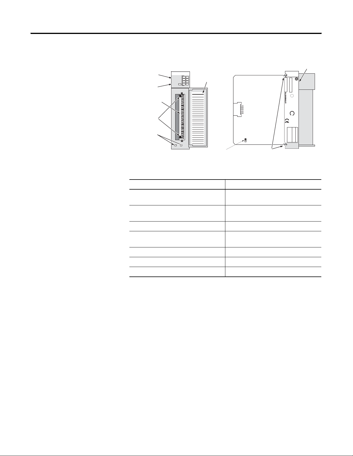
Hardware Features
The module fits into any single slot for I/O modules in either an SLC
500 modular system or an SLC 500 fixed system expansion chassis
(1746-A2), except the zero slot which is reserved for the processor. It
is a Class 1 module using 8 input words and 8 output words.
The module contains a removable terminal block providing
connections for eight thermocouple and/or analog input devices. On
the terminal block are two cold-junction compensation (CJC) sensors
that compensate for the cold junction at ambient temperature. It
should also be noted there are no output channels on the module.
Configure the module with software rather than with jumpers or
switches.
(2)
Publication 1746-UM022B-EN-P - January 2005
IMPORTANT
There is a jumper (JP1) on the circuit board. The
module is shipped with the jumper in the up
position as illustrated below. Do not change the
position of JP1. The jumper is used for test purposes
only.
(1) Output impedance of input device must be less than 100 ohm to meet accuracy specifications.
(2) Requires use of a Block Transfer when used in a remote rack with a 1747-ASB.
Page 13
Module Overview 1-3
Channel Status
LEDs (green)
Module Status
LEDs (green)
Removable
Terminal Block
CJC Sensors
Cable Tie Slots
INPUT
CHANNEL
014
5
2
123
Door Label
1746-NT8
CJC A+
CJC ACHL 0+
CHL 0SHIELD
CHL 1+
CHL 1CHL 2+
CHL 2SHIELD
CHL 3+
CHL 3CHL 4+
CHL 4SHIELD
CHL 5+
CHL 5CHL 6+
CHL 6SHIELD
CHL 7+
CHL 7CJC B+
CJC B-
Jumper - Do not move
JP1
Self-Locking Tabs
STATUS
MODULE
THERMOCOUPLE/mV
Side Label
CAT
SERIAL NO.
1746 NT4
NT4±xxx x
THERMOCOUPLE/mV INPUT MODULE
SLC 500
SER
FRN
)
CLASS I, GROUPS A, B, C AND D, DIV.2
U
L
FOR HAZ. LOC. A196
LISTED IND. CONT . EQ.
SA
)
OPERA TING
TEMPERA TURE
CODE T3C
THERMOCOUPLE TYPES:
VOLTAGE:
INPUT SIGNAL RANGES
±100mVDC to +100mVDC
±50mVDC to +50mVDC
J, K, T, E, R, S, B, N
MADE IN USAFAC 1M
Hardware Features
Hardware Function
Channel Status LED Indicators Display operating and fault status of
channels 0 to 7
Module Status LED Displays operating and fault status of the
module
Side Label (Nameplate) Provides module information
Removable Terminal Block Provides electrical connection to input
devices
System Overview
Door Label Permits easy terminal identification
Cable Tie Slots Secure and route wiring from module
Self Locking Tabs Secure module in chassis slot
Diagnostic LEDs
The module contains diagnostic LEDs that help you identify the
source of problems that may occur during power-up or during normal
operation. Power-up and channel diagnostics are explained in
Chapter 6, Testing Your Module.
The module communicates with the SLC 500 processor and receives
+5V dc and +24V dc power from the system power supply through
the parallel backplane interface. No external power supply is
required. You may install as many thermocouple modules in the
system as the power supply can support.
Publication 1746-UM022B-EN-P - January 2005
Page 14
1-4 Module Overview
Each module channel can receive input signals from a thermocouple
or a mV analog input device. You configure each channel to accept
either one. When configured for thermocouple input types, the
module converts analog input voltages into cold-junction
compensated and linearized, digital temperature readings. The
module uses National Institute of Standards and Technology (NIST)
ITS-90 for thermocouple linearization.
When configured for millivolt analog inputs, the module converts
analog values directly into digital counts. The module assumes that
the mV input signal is linear.
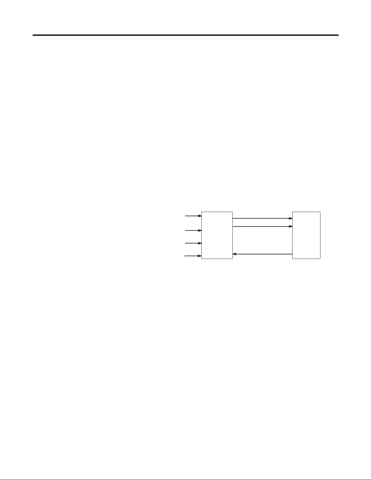
System Operation
At power-up, the module checks its internal circuits, memory, and
basic functions. During this time the module status LED remains off. If
the module finds no faults, it turns on its module status LED.
Channel Data Word
Channel Status Word
Therm ocouple or mV
Analog Signals
Thermocou ple
Input
Module
Channel Co nfiguration Word
SL C 5 00
P rocess or
After completing power-up checks, the module waits for valid channel
configuration data from your SLC ladder logic program (channel status
LEDs are off). After channel configuration data is transferred and
channel enable bits are set, the enabled channel status LEDs turn on.
Then the channel continuously converts the thermocouple or millivolt
input to a value within the range you selected for the channel.
Each time the module reads an input channel, the module tests that
data for a fault, i.e. over-range or under-range condition. If open
circuit detection is enabled, the module tests for an open-circuit
condition. If it detects an open-circuit, over-range, or under-range
condition, the module sets a unique bit in the channel status word
and causes the channel status LED to flash.
The SLC processor reads the converted thermocouple or millivolt data
from the module at the end of the program scan, or when
commanded by the ladder program. After the processor and module
determine that the data transfer was made without error, the data can
be used in your ladder program.
Publication 1746-UM022B-EN-P - January 2005
Page 15

Module Overview 1-5
Module Operation
The module’s input circuitry consists of eight differential analog
inputs, multiplexed into an A/D convertor. The A/D convertor reads
the analog input signals and converts them to a digital value. The
input circuitry also continuously samples the CJC sensors and
compensates for temperature changes at the cold junction (terminal
block).
Module Addressing
The module requires eight words each in the SLC processor’s input
and output image tables. Addresses for the module in slot e are as
follows:
I:e.0-7 thermocouple/mV or status data for channels 0 to 7,
respectively (dependent on bit in configuration word).
O:e.0-7 configuration data for channels 0 to 7, respectively.
See Module Addressing on page 3-2 to see the module’s image table.
Publication 1746-UM022B-EN-P - January 2005
Page 16
1-6 Module Overview
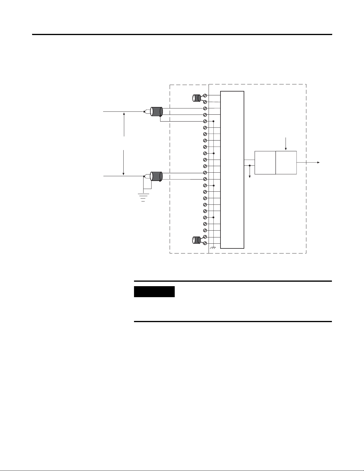
Block Diagram
ungrounded
thermocouple
Wit hin
12.5V
grounded
thermocouple
Terminal Block Module Circuitry
CJCA Sens or
+
-
+
-
Shield
+
-
+
-
Shield
+
-
Shield
multiplexer
Analog
Ground
Analog to
Digital
Converter
User S elected
Filter F requency
+
-
+
-
Shield
+
-
+
CJCB S ensor
-
Digital
Filter
Digital
Va lue
Publication 1746-UM022B-EN-P - January 2005
IMPORTANT
When using multiple thermocouples, the potential
between any two channels cannot exceed the
channel-to-channel differential voltage (12.5 volts).
For more information, see Appendix B.
Page 17
Module Overview 1-7
Linear Millivolt Device Compatibility
(1)
A large number of millivolt devices may be used with the 1746-NT8
module. For this reason we do not specify compatibility with any
particular device.
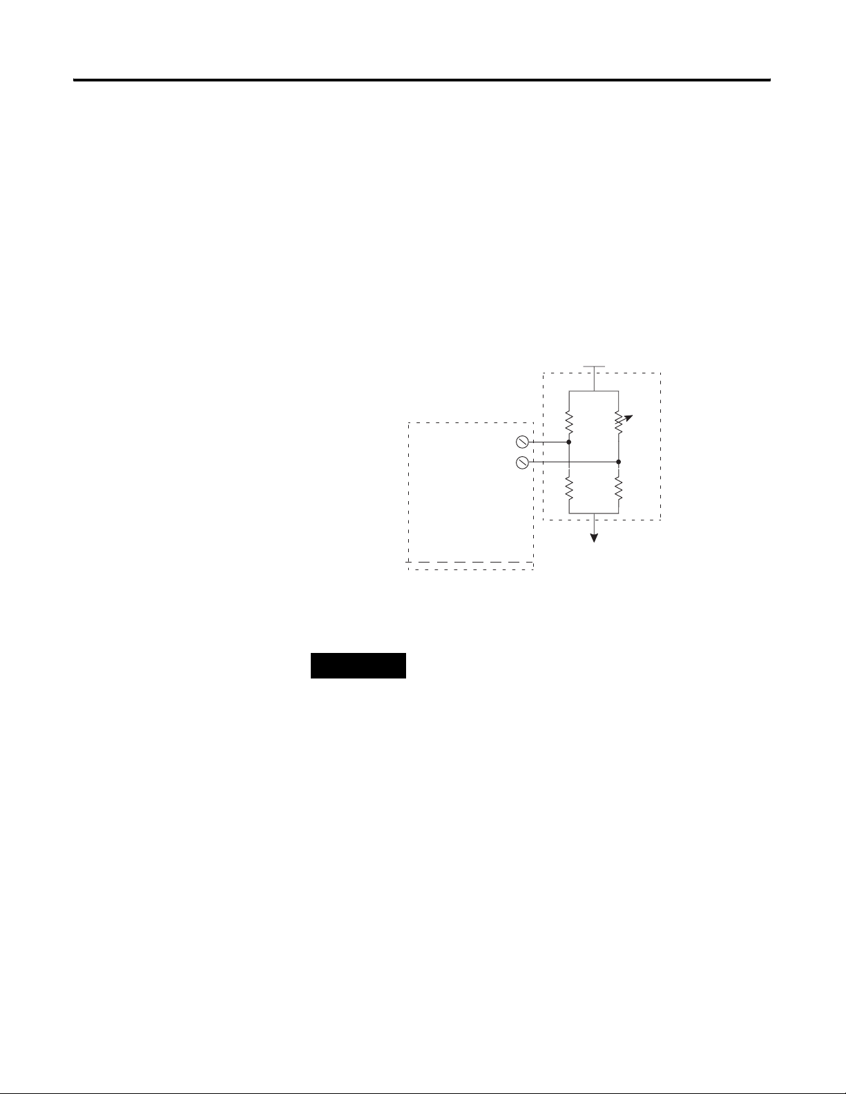
However, millivolt applications often use strain gage bridges. A
resistive voltage divider using fixed resistors is recommended for this
application. The circuit diagram below shows how this connection is
made.
Strain
Gage
Voc
+
variable
fixed
1746-NT8
Channel
Input
Bridge
fixed
+
-
fixed
TIP
The resistors should be selected to ensure that the
differential input voltage is less than or equal to ±100
mV.
(1) Output impedance of input device must be less than 100 ohm to meet accuracy specifications.
Publication 1746-UM022B-EN-P - January 2005
Page 18

1-8 Module Overview
Publication 1746-UM022B-EN-P - January 2005
Page 19

Chapter
Installing And Wiring Your Module
Read this chapter to install and wire your module. This chapter
covers:
• avoiding electrostatic damage
• determining power requirements
• installing the module
• wiring signal cables to the module’s terminal block
2
Electrostatic Damage
Electrostatic discharge can damage semiconductor devices inside this
module if you touch backplane connector pins. Guard against
electrostatic damage by observing the following precautions:
ATTENTION
Electrostatically Sensitive Components
• Before handling the module, touch a grounded
object to rid yourself of electrostatic charge.
• Handle the module from the front, away from the
backplane connector. Do not touch backplane
connector pins.
• Keep the module in its static-shield container
when not in use or during shipment.
Failure to observe these precautions can degrade the
module’s performance or cause permanent damage.
1 Publication 1746-UM022B-EN-P - January 2005
Page 20

2-2 Installing And Wiring Your Module
Power Requirements
The module receives its power through the SLC 500 chassis backplane
from the fixed or modular +5 V dc/+24 V dc chassis power supply.
The maximum current drawn by the module is shown in the table
below.
Maximum Current Drawn by the Module
5Vdc Amps 24Vdc Amps
0.120 0.070
Considerations for a Modular System
Place your module in any slot of an SLC 500 modular, or modular
expansion chassis, except for the left-most slot (slot 0) reserved for
the SLC processor or adapter modules.
When using the module with a modular system, add the values shown
above to the requirements of all other modules in the SLC to prevent
overloading the chassis power supply. Refer to the SLC 500 Modular
Hardware Style User Manual, publication 1747-UM011.
Publication 1746-UM022B-EN-P - January 2005
Page 21
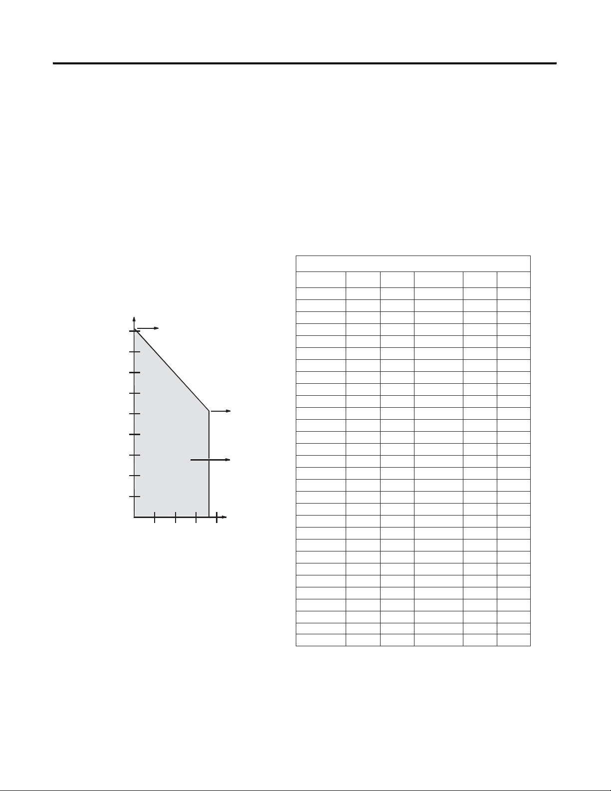
Fixed I/O Chassis - I/O Module Compatibility
The following chart depicts the range of current combinations
supported by the fixed I/O expansion chassis. To use it, find the
backplane current draw and operating voltage for both modules being
used in the chassis. These specifications are found in the table
alongside the chart.
Next, plot each of the currents on the chart below. If the point of
intersection falls within the operating region, the combination is valid.
If not, the combination cannot be used in a 2-slot, fixed I/O chassis.
OW16 and
450
400
350
300
250
Current
(mA)
at 5V dc
200
150
100
50
Example: Plot IN16 and NIO4V
IN16 = 0.085 at 5V dc and 0A at 24V dc
NIO4V = 0.055A at 5V dc and 0.115A at 24V dc
1. Add current draws of both modules at 5V dc to get
0.14 A (140 mA).
2. Plot this point on the chart above (140 mA at 5V dc.
3. Add current draws of both modules at 24V dc to get
0.115 A (115 mA).
4. Plot current draw at 24V dc (115 mA at 24V dc).
5. Note the point of intersection on the chart above
(marked x). This combination falls within the valid
operating region for the fixed I/O chassis.
(0, 455)
Valid Operating
Region
x
50 150 200
100
Current (mA) at 24V
OW16 and IA16
(180, 255)
Plotted from
Example
Shown Below
Installing And Wiring Your Module 2-3
Module Current Draw - Power Supply Loading
I/O Module
BAS .150 .040
BASn .150 .125
DCM .360 .000
FI O4I .055 .150
FI O4V .055 .120
HS .300 .000
HSTP 1 .200 .000
IA4 .035 .000
IA8 .050 .000 NR4 .050 .05 0
IA16 .085 .000
IB8 .050 .000
IB16 .085 .000
IB32 .106 .000
IC16 .085 .000
IG16 .140 .000
IH16 .085 .000
IM4 .035 .000
IM8 .050 .000
IM16 .085 .000
IN16 .085 .000
IO4 .030 .025
IO8 .060 .045
IO12 .090 .070
ITB16 .085 .000
ITV16 .085 .000
IV8 .050 .000
IV16 .085 .000
IV32 .106 .000
KE .150 .040
KEn .125
5V 24V I/O Module 5V 24V
NI4 .025 .085
NI8 .200 .100
NIO4I .055 .145
NIO4V .055 .115
NO4I .055 .195
NO4V .055 .145
120
100 55
120 70
.150
N08I
N08V 120 160*
NR8
NT4 .060 .040
NT8
OA16 .370 .00 0
OA8 .185 .000
OAP 12 .370 .000
OB8 .135 .000
OB16 .280 .000
OB16E .135 .000
OB32 .452 .000
OBP8 .135 .000
OBP16 .250 .000
OG16 .180 .00 0
OV8 .135 .000
OV16 .270 .000
OV32 .452 .000
OVP 16 .250 .000
OW16 .170 .180
OW4 .045 .045
OW8 .085 .090
OX8 .085 .090
250*
* w/jumper set to rack, otherwise 0.0 mA.
Important: The 1747-NO4I and 1746-NO4V analog
output modules may require an external power
supply.
Publication 1746-UM022B-EN-P - January 2005
Page 22

2-4 Installing And Wiring Your Module
When using the BAS or KE module to supply power to a 1747-AIC
Link Coupler, the link coupler draws its power through the module.
The higher current drawn by the AIC at 24V dc is shown in the table
as BASn (BAS networked) and KEn (KE networked). Be sure to use
these current draw values if the application uses the BAS or KE
module in this way.
General Considerations
Most applications require installation in an industrial enclosure to
reduce the effects of electrical interference. Thermocouple inputs are
highly susceptible to electrical noises due to the small amplitudes of
their signal (microvolt/°C).
Group your modules to minimize adverse effects from radiated
electrical noise and heat. Consider the following conditions when
selecting a slot for the thermocouple module. Position the module:
• in a slot away from sources of electrical noise such as recontact
switches, relays, and AC motor drives
• away from modules which generate significant radiated heat,
such as the 32-point I/O modules
In addition, route shielded twisted pair thermocouple or millivolt
input wiring away from any high voltage I/O wiring.
Remember that in a modular system, the processor or communications
adapter always occupies the first slot of the chassis.
Publication 1746-UM022B-EN-P - January 2005
Page 23
Module Installation and Removal
ATTENTION
Installing And Wiring Your Module 2-5
Possible Equipment Operation
Before installing or removing your module, always
disconnect power from the SLC 500 system and from
any other source to the module (in other words, do
not ’hot swap’ your module), and disconnect any
devices wired to the module.
Failure to observe this precaution can cause
unintended equipment operation and damage.
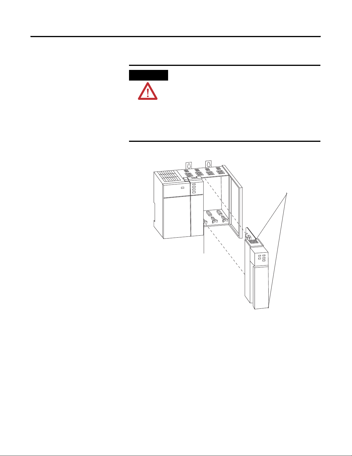
Top and Bottom
Module Release(s)
Card Guide
To insert your module into the chassis, follow these steps:
1. Before installing the module, connect the ground wire to TB1.
See the figure on page 2-10.
2. Align the circuit board of your module with the card guides at
the top and bottom of the chassis.
3. Slide your module into the chassis until both top and bottom
retaining clips are secure. Apply firm even pressure on your
module to attach it to its backplane connector. Never force your
module into the slot.
Publication 1746-UM022B-EN-P - January 2005
Page 24

2-6 Installing And Wiring Your Module
4. Cover all unused slots with the Card Slot Filler, Allen-Bradley
part number 1746-N2.
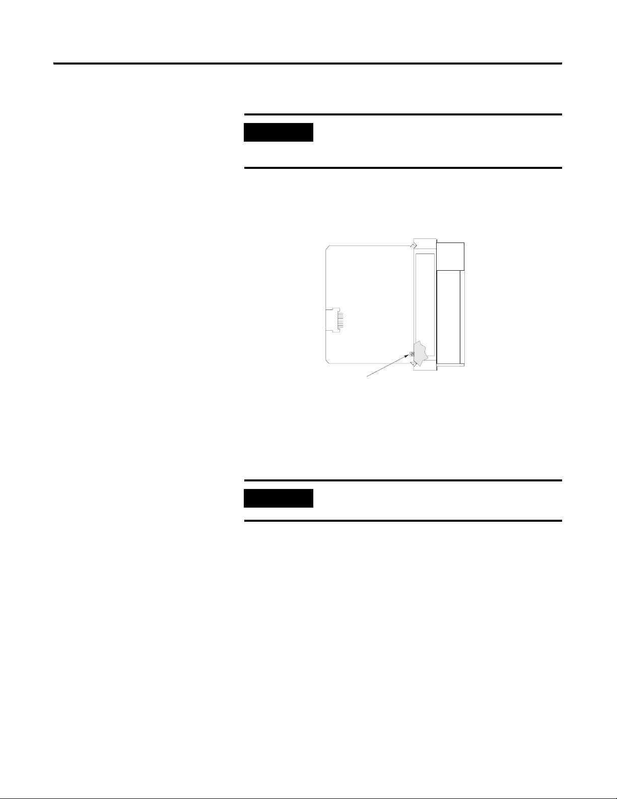
Terminal Block Removal
To remove the terminal block:
1. Loosen the two terminal block release screws. To avoid cracking
the terminal block, alternate between screws as you remove
them.
2. Using a screwdriver or needle-nose pliers, carefully pry the
terminal block loose. When removing or installing the terminal
block be careful not to damage the CJC sensors.
Publication 1746-UM022B-EN-P - January 2005
Page 25
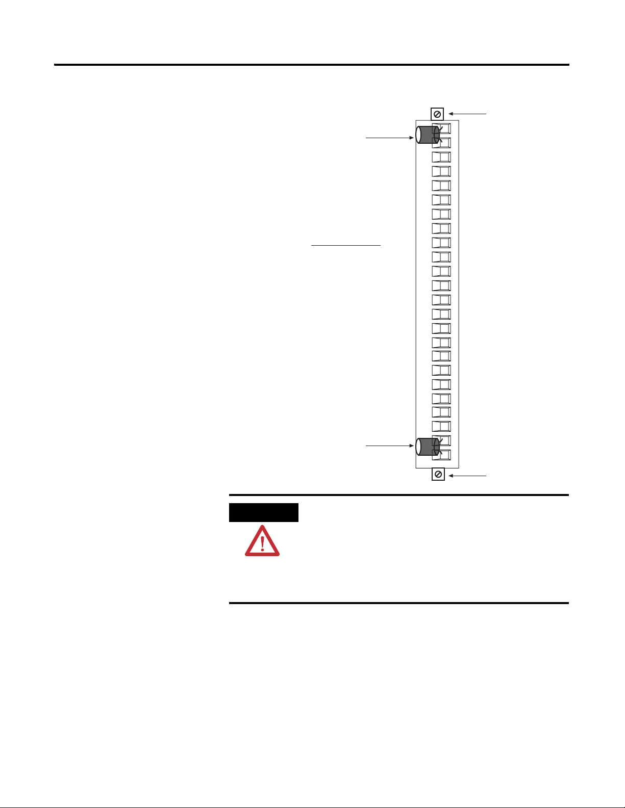
Terminal block diagram with CJC sensors
CJC Sensors
Recomm ended Torque:
wiring screws: 0.25 Nm (2.2 in-lb)
release scre ws: 0.25 Nm (2.2 in-lb)
Installing And Wiring Your Module 2-7
Terminal Block
Release Screws
ATTENTION
CJC Sensors
Terminal Block
Release Screws
Possible Equipment Operation
Before wiring your module, always disconnect
power from the SLC 500 system and from any other
source to the module.
Failure to observe this precaution can cause
unintended equipment operation and damage.
Publication 1746-UM022B-EN-P - January 2005
Page 26

2-8 Installing And Wiring Your Module
Wiring Your Module
Follow these guidelines to wire your input signal cables:
• Power, input, and output (I/O) wiring must be in accordance
with Class 1, Division 2 wiring methods [Article 501-4(b) of the
National Electrical Code, NFPA 70] and in accordance with the
authority having jurisdiction.
• Route thermocouple and millivolt signal wires as far as possible
from sources of electrical noise, such as motors, transformers,
contactors, and ac devices. As a general rule, allow at least 6 in.
(about 15.2 cm) of separation for every 120V ac of power.
• Routing the field wiring in a grounded conduit can reduce
electrical noise further.
• If the field wiring must cross ac or power cables, ensure that
they cross at right angles.
• For high immunity to electrical noise, use Belden™ 8761
(shielded, twisted pair) or equivalent wire for millivolt sensors;
or use shielded, twisted pair thermocouple extension lead wire
specified by the thermocouple manufacturer. Using the incorrect
type of convention thermocouple extension wire or not
following the correct polarity may cause invalid readings.
• Ground the shield drain wire at only one end of the cable. The
preferred location is at the shield connections on the terminal
block. (Refer to IEEE Std. 518, Section 6.4.2.7 or contact your
sensor manufacturer for additional details.)
• Keep all unshielded wires as short as possible.
• Excessive tightening can strip a screw. Tighten screws to 0.25
Nm (2.2 in-lb) or less, based on UL 1059, CSA C22.2 No. 158,
VDE 0110B 2.79 standards.
• Follow system grounding and wiring guidelines found in your
SLC 500 Modular Hardware Style User Manual, publication
1747-UM011 or 1747-SLC 500 Fixed Hardware Style User
Manual, publication 1747-6.21.
Publication 1746-UM022B-EN-P - January 2005
Page 27

Installing And Wiring Your Module 2-9
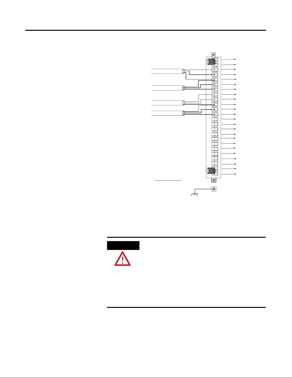
Preparing and Wiring the Cables
To prepare and connect cable leads and drain wires, follow these
steps:
Cable
Signal Wires
(Remove foil shield and drain wire
from sensor end of the cable.)
Drain Wire
Signal Wires
1. At each end of the cable, strip some casing to expose individual
wires.
2. Trim signal wires to 5-inch lengths beyond the cable casing.
Strip about 3/16 inch (4.76 mm) of insulation to expose the ends
of the wires.
3. At the module end of the cables:
• extract the drain wire and signal wires
• remove the foil shield
• bundle the input cables with a cable strap
4. Connect pairs of drain wires together:
• Channels 0 and 1
• Channels 2 and 3
• Channels 4 and 5
• Channels 6 and 7
Keep drain wires as short as possible.
5. Connect the drain wires to the shield inputs of the terminal
block if appropriate for thermocouple used.
• Channel 0 and 1 drain wires to pin 5
• Channel 2 and 3 drain wires to pin 10
• Channel 4 and 5 drain wires to pin 15
• Channel 6 and 7 drain wires to pin 20
Publication 1746-UM022B-EN-P - January 2005
Page 28
2-10 Installing And Wiring Your Module
6. Connect the signal wires of each channel to the terminal block.
IMPORTANT
Only after verifying that your connections are
correct for each channel, trim the lengths to keep
them short. Avoid cutting leads too short.
7. Connect TB1 chassis ground connector to the nearest chassis
mounting bolt with 14 gauge wire. (Looking at the face of the
module, TB1 is near the lower part of the terminal block on the
primary side of the PCB.)
TB1
Connect ground wire to TB1
before installing module.
8. At the sensor end of cables from thermocouple/mV devices:
• remove the drain wire and foil shield
• apply shrink wrap as an option
• connect to mV devices keeping the leads short.
IMPORTANT
If noise persists, try grounding the opposite end
of the cable. Ground one end only.
Publication 1746-UM022B-EN-P - January 2005
Page 29
Terminal Block Diagram with Input Cable
Thermocouple or mV Ca ble
Recommended Torque :
TB 1 0.3 to 0.5 Nm (2.5 to 4.5 in-lb)
Installing And Wiring Your Module 2-11
CJC A+
CJC AChannel 0+
Channel 0-
Shield for CH0 and CH 1
Channel 1+
Channel 1-
Channel 2+
Channel 2-
Shield for CH2 and CH 3
Channel 3+
Channel 3Channel 4+
Channel 4Shield for CH4 and CH 5
Channel 5+
Channel 5-
Channel 6+
Channel 6-
Shield for CH6 and CH 7
Channel 7+
Channel 7-
CJC B +
CJC B -
TB1
The module also has a ground terminal TB1, which should be
grounded to a chassis mounting bolt with 14-gauge wire.
Cold-Junction Compensation (CJC)
ATTENTION
To obtain accurate readings from each of the channels, the
cold-junction temperature (temperature at the module’s terminal
junction between the thermocouple wire and the input channel) must
be compensated for. Two cold-junction compensating sensors have
been integrated in the removable terminal block. They must remain
installed.
Possible Equipment Operation
Do not remove or loosen the cold-junction
compensating temperature transducers located on
the terminal block. Both CJCs are required to ensure
accurate thermocouple input readings at each
channel. The module will not operate in
thermocouple mode if a CJC is not connected.
Failure to observe this precaution can cause
unintended equipment operation and damage.
Publication 1746-UM022B-EN-P - January 2005
Page 30

2-12 Installing And Wiring Your Module
Publication 1746-UM022B-EN-P - January 2005
Page 31

Chapter
3
Module ID Code
Considerations Before Using
This chapter explains how the module and the SLC processor
communicate through the processor’s I/O image tables. It also
describes the module’s input filter characteristics. Topics discussed
include:
• module ID code
• module addressing
• channel filter frequency selection
• channel turn-on, turn-off, and reconfiguration times
• response to slot disabling
The module ID code is unique number assigned to each 1746 I/O
module. The ID code defines the type of I/O module and the number
of words used in the processor’s I/O image table.
Your Module
The module ID code for the 1746-NT8 module is 3533.
No special I/O configuration is required. The module ID automatically
assigns the correct number of input and output words.
1 Publication 1746-UM022B-EN-P - January 2005
Page 32

3-2 Considerations Before Using Your Module
Module Addressing
SLC 5/0X
Data Files
Slot e
Output Image
Slot e
Input Image
Output
Scan
Input
Scan
The following memory map shows you how the SLC processor’s
output and input tables are defined for the module.
Image Table
Thermocouple
Module
Image Table
Output Image
8 Words
Input Image
8 Words
Bit 15
Channel 0 Configuration Word
Channel 1 Configuration Word
Channel 2 Configuration Word
Bit 15
Channel 3 Configuration Word
Channel 4 Configuration Word
Channel 5 Configuration Word
Channel 6 Configuration Word
Channel 7 Configuration Word
Channel 0 Data or Status Word
Channel 1 Data or Status Word
Channel 2 Data or Status Word
Channel 3 Data or Status Word
Channel 4 Data or Status Word
Channel 5 Data or Status Word
Channel 6 Data or Status Word
Channel 7 Data or Status Word
Bit 0
Word 0
Word 1
Word 2
Word 3
Word 4
Word 5
Word 6
Word 7
Word 0
Word 1
Word 2
Word 3
Word 4
Word 5
Word 6
Word 7
Bit 0
Address
O:e.0
O:e.1
O:e.2
O:e.3
O:e.4
O:e.5
O:e.6
O:e.7
I:e.0
I:e.1
I:e.2
I:e.3
I:e.4
I:e.5
I:e.6
I:e.7
Address
Output Image - Configuration Words
Eight words of the SLC processor’s output image table are reserved for
the module. Output image words 0 through 7 are used to configure
the module’s input channels 0 through 7. Each output image word
configures a single channel and can be referred to as a configuration
word. Each word has a unique address based on the slot number
assigned to the module.
Example Address - If you want to configure channel 2 on the
module located in slot 4 in the SLC chassis, your address would be
O:4.2.
Slot
File Type
Elem ent
Delimiter
O:4.2
Word
Word
Delimiter
Publication 1746-UM022B-EN-P - January 2005
Page 33

Considerations Before Using Your Module 3-3
Chapter 4 provides detailed bit information about the data content of
the configuration word.
Input Image - Data Words and Status Words
Eight words of the SLC processor’s input image table are reserved for
the module. Input image words are multiplexed since each channel
has one data word and one status word. The corresponding
configuration word selects whether the channel status or channel data
is in the input image word.
Status bits for a particular channel reflect the configuration settings
that you entered into the configuration (output image) word for that
channel. To receive valid status, the channel must be enabled and the
module must have stored a valid configuration word for that channel.
Each input image word has a unique address based on the slot
number assigned to the module.
Channel Filter Frequency Selection
Example Address - To obtain the status/data word of channel 2
(input word 2) of the module located in slot 4 in the SLC chassis use
address I:4:2.
File Type
Slot
Word
I:4.2
E lement
Delimiter
Word
Delimiter
Chapter 4 provides detailed bit information about the content of the
data word and the status word.
The thermocouple module uses a digital filter that provides
high-frequency noise rejection for the input signals. The digital filter is
programmable, allowing you to select from four filter frequencies for
each channel. The digital filter provides the highest noise rejection at
the selected filter frequency. The graphs to follow show the input
channel frequency response for each filter frequency selection.
Selecting a low value (i.e. 10 Hz) for the channel filter frequency
provides the best noise rejection for a channel, but it also increases
the channel update time. Selecting a high value for the channel filter
frequency provides lower noise rejection, but decreases the channel
update time.
Publication 1746-UM022B-EN-P - January 2005
Page 34

3-4 Considerations Before Using Your Module
The following table shows the available filter frequencies, cut-off
frequency, step response, and a DC effective resolution for each filter
frequency.
Cut-off frequency, Step Response Time, and Effective Resolution (Based on Filter
Frequency)
Filter Frequency Cut-Off Frequency Step Response ADC Effective
Resolution
10 Hz 2.62 Hz 400 ms 20.5
50 Hz 13.1 Hz 80 ms 19.0
60 Hz 15.72 Hz 66.7 ms 19.0
250 Hz 65.5 Hz 16 ms 15.5
The step response is calculated by a 4 x (1/filter frequency) settling
time.
Channel Cut-Off Frequency
The channel filter frequency selection determines a channel’s cut-off
frequency, also called the -3 dB frequency. The cut-off frequency is
defined as the point on the input channel frequency response curve
where frequency components of the input signal are passed with 3 dB
of attenuation. All frequency components at or below the cut-off
frequency are passed by the digital filter with less than 3 dB of
attenuation. All frequency components above the cut-off frequency
are increasingly attenuated, as shown in the graphs on page 3-5.
The cut-off frequency for each input channel is defined by its filter
frequency selection. The table above shows the input channel cut-off
frequency for each filter frequency. Choose a filter frequency so that
your fastest changing signal is below that of the filter’s cut-off
frequency. The cut-off frequency should not be confused with update
time. The cut-off frequency relates how the digital filter attenuates
frequency components of the input signal. The update time defines
the rate at which an input channel is scanned and its channel data
word updated.
Publication 1746-UM022B-EN-P - January 2005
Page 35

Signal Attenuation with 10 Hz Input Filter
Considerations Before Using Your Module 3-5
-3 dB
0
-20
-40
-60
-80
Amplitude (in dB)
-100
-120
-140
-160
-180
-200
2.62 Hz
0
10
20
Signal Attenuation with 50 Hz Input Filter
-3 dB
Amplitude (in dB)
0
-20
-40
-60
-80
-100
-120
-140
-160
-180
-200
0 50 100 150 200 250 300 Hz
30
Signal Frequency
40
50
60 Hz
13.1 Hz
Signal Frequency
Publication 1746-UM022B-EN-P - January 2005
Page 36

3-6 Considerations Before Using Your Module
Signal Attenuation with 60 Hz Input Filter
-3 dB
Amplitude (in dB)
0
-20
-40
-60
-80
-100
-120
-140
-160
-180
-200
0 60 120 180 240 300 360 Hz
15.7 Hz
Signal Attenuation with 250 Hz Input Filter
-3 dB
Amplitude (in dB)
0
-20
-40
-60
-80
-100
-120
-140
-160
-180
-200
0 250 500 750 1000 1250 1500 Hz
Signal Fr equency
Publication 1746-UM022B-EN-P - January 2005
65.5 Hz
Signal Fr equency
Channel Step Response
The channel filter frequency determines the channel’s step response.
The step response is time required for the analog input signal to reach
95% of its expected, final value given a full-scale step change in the
input signal. This means that if an input signal changes faster than the
channel step response, a portion of that signal will be attenuated by
the channel filter. The table on page 3-4 shows the step response for
each filter frequency.
Page 37

Considerations Before Using Your Module 3-7
Update Time
The thermocouple module update time is defined as the time required
for the module to sample and convert the input signals of all enabled
input channels and make the resulting data values available to the SLC
processor. It can be calculated by adding the sum of all enabled
sample times, plus a CJC update time.
Channel 0 Disabled Channel 1 Disabled
Enabled
Sample
Channel 0
Update CJC
Enabled Enabled Enabled
Sample
Channel 1
Calculate
Previous
The following table shows the channel sampling time for each filter
frequency. It also gives the CJC update time.
Channel Sampling Time
Channel Sampling Time for Each Filter Frequency (all values ±1 ms)
CJC Update Time 250 Hz Filter 60 Hz Filter 50 Hz Filter 10 Hz Filter
290 ms 66 ms 125 ms 140 ms 470 ms
Channel 2 Disabled Channel 7 Disabled
Sample
Channel 2
Calculate
Previous
Sample
Channel 7
Calculate
Previous
Sample
CJC
Channel
Calculate
Previous
The times above include a settling time necessary between input
channel readings. The sampling times for filter frequencies listed do
not include a 45 ms open-circuit detection time utilized when the
channel is configured for open-circuit detection. CJC open-circuit
detection does not require the additional 45 ms settling time.
The fastest module update time occurs when only one channel with a
250 Hz filter frequency is enabled.
Module update time = 290 ms + 66 ms = 356 ms
The slowest module update time occurs when eight channels, each
using a 10 Hz filter frequency, are enabled.
Module update time = 290 ms + 470 ms + 470 ms + 470 ms + 470
ms + 470 ms + 470 ms + 470 ms + 470 ms = 4.05 s
Publication 1746-UM022B-EN-P - January 2005
Page 38

3-8 Considerations Before Using Your Module
Update Time Calculation Example
The following example shows how to calculate the module update
time for the given configuration:
Channel 0 configured for 250 Hz filter frequency, enabled
Channel 1 configured for 250 Hz filter frequency, enabled
Channel 2 configured for 50 Hz filter frequency, enabled
Channel 3 through 7 disabled
Using the values from the table on page 3-7, add the sum of all
enabled channel sample times, plus one CJC update time.
Channel 0 sampling time = 66 ms
Channel 1 sampling time = 66 ms
Channel 2 sampling time = 140 ms
CJC update time = 290 ms
Module update time = 562 ms
Channel Turn-On, Turn-Off, and Reconfiguration Times
Auto-calibration
The time required for the module to recognize a new configuration
for a channel is generally one module update time plus 890 µs per
newly configured channel. If the filter frequency selected for the
newly enabled, configured channel is new to the module, then
auto-calibration is performed following configuration recognition.
Turn-off time requires up to one module update time.
Reconfiguration time is the same as turn-on time.
Auto-calibration is performed by the module to correct for drift errors
over temperature. Auto-calibration occurs immediately following
configuration of a previously unselected filter frequency, and
generally every two minutes for all selected filter frequencies of the
system. The time required to perform auto-calibration is defined as
follows:
Auto-calibration Time
250 Hz Filter 60 Hz Filter 50 Hz Filter 10 Hz Filter
325 ms 525 ms 585 ms 1.975 s
Publication 1746-UM022B-EN-P - January 2005
Page 39

Considerations Before Using Your Module 3-9
CJC sensors are acquired at 60 Hz to maximize the trade-off between
resolution and update rate. For example, if some channels are
acquired at 250 Hz and some are acquired at 50 Hz, then the total
auto-calibration time would be:
Frequency Auto-Calibration
250 Hz 325 ms
60 Hz 525 ms
50 Hz 585 ms
1.435 s Total
During auto-calibration, input values are not updated.
Response to Slot Disabling
By writing to the status file in the modular SLC processor, you can
disable any chassis slot. Refer to your SLC programming manual for
the slot disable/enable procedure.
ATTENTION
Possible Equipment Operation
Always understand the implications of disabling a
module before using the slot disable feature.
Failure to observe this precaution can cause
unintended equipment operation.
Input Response
When a thermocouple slot is disabled, the thermocouple module
continues to update its input image table. However, the SLC processor
does not read input from a module that is disabled. Therefore, when
the processor disables the thermocouple module slot, the module
inputs appearing in the processor image table remain in their last
state, and the module’s updated image table is not read. When the
processor re-enables the module slot, the current state of the module
inputs are read by the processor during the subsequent scan.
Output Response
The SLC processor may change the thermocouple module output data
(configuration) as it appears in the processor output image. However,
this data is not transferred to the thermocouple module. The outputs
are held in their last state. When the slot is re-enabled, the data in the
processor image is transferred to the thermocouple module.
Publication 1746-UM022B-EN-P - January 2005
Page 40

3-10 Considerations Before Using Your Module
Publication 1746-UM022B-EN-P - January 2005
Page 41

Chapter
Channel Configuration, Data, and Status
Read this chapter to:
• configure each input channel
• check each input channel’s configuration and status
4
Channel Configuration
Channel configuration words appear in the SLC processor’s output
image table as shown below. Words 0 to 7 correspond to module
channels 0 to 7.
After module installation, configure each channel to establish the way
the channel operates (e.g., thermocouple type, temperature units,
etc.). Configure the channel by setting bits in the configuration word
using your programming device. The SLC configuration words are
shown below.
SLC Output Image (Configuration) Words
bit 0
O:e.0
O:e.1
O:e.2
O:e.3
O:e.4
bit 15
Channel 0 Channel Configuration Word
Channel 1 Channel Configuration Word
Channel 2 Channel Configuration Word
Channel 3 Channel Configuration Word
Channel 4 Channel Configuration Word
O:e.5
O:e.6
O:e.7
Channel 5 Channel Configuration Word
Channel 6 Channel Configuration Word
Channel 7 Channel Configuration Word
e = slot number of the module
1 Publication 1746-UM022B-EN-P - January 2005
Page 42

4-2 Channel Configuration, Data, and Status
The configuration word default settings are all zero. Next, we describe
how you set configuration bits of a channel configuration word to set
up the following channel parameters:
• data format such as engineering units, counts, or scaled-for-PID
• how the channel should respond to a detected open-input
circuit
• filter frequency selection
• temperature units in °C or °F
• whether the channel is enabled or disabled
• whether status or data information is selected for the module’s
input image table
Channel Configuration Procedure
The channel configuration word consists of bit fields, the settings of
which determine how the channel operates. This procedure looks at
each bit field separately and helps configure a channel for operation.
Refer to the chart on page 4-4 and the bit field descriptions that follow
for complete configuration information.
TIP
1. Determine which channels are used in your program and enable
them. Place a one in bit 0 if the channel is to be enabled. Place
a zero in bit 0 if the channel is to be disabled.
2. Determine the input device type (J, K, etc. thermocouple) (or
mV) for a channel and enter its respective four-digit binary code
in bit field 1 through 4 of the channel configuration word.
3. Select a data format for the data word. Your selection determines
how the analog input value from the A/D converter will be
expressed in the data word. Enter your two-digit binary code in
bit field 5 and 6 of the channel configuration word.
When using RSLogix 500 version 6.10 or higher, you
can use the software’s I/O wizard to configure the
NT8 channels. Refer to Appendix C for more
information.
Publication 1746-UM022B-EN-P - January 2005
4. Determine the desired state for the channel data word if an
open-circuit condition is enabled and detected for that channel.
Enter the two-digit binary code in bit field 7 and 8 of the
channel configuration word.
Page 43

Channel Configuration, Data, and Status 4-3
5. If the channel is configured for thermocouple inputs, determine
if the channel data word should read in degrees Fahrenheit or
degrees Celsius and enter a one or a zero in bit 9 of the
configuration word. If the channel is configured for a mV analog
sensor, enter a zero in bit 9.
6. Determine the desired input filter frequency for the channel and
enter the two-digit binary code in bits 10 and 11 of the channel
configuration word. A lower filter frequency increases the
channel update time, but also increases the noise rejection and
channel resolution. A higher filter frequency decreases the
channel update time, but also decreases the noise rejection and
effective resolution.
7. Ensure that bits 12 through 14 contain zeros.
8. Determine whether the channel input image word should
contain data or status. Place a one in bit 15 if channel data is
desired. Place a zero in bit 15 if status is desired.
9. Build the channel configuration word for every channel on each
thermocouple/mV module repeating the procedures given in
steps 1 through 8.
10. Enter this configuration into your ladder program and download
it to the thermocouple module.
Publication 1746-UM022B-EN-P - January 2005
Page 44

4-4 Channel Configuration, Data, and Status
A detailed explanation appears in the following table:
Channel Configuration Word (0:e.0 through 0:e.7) - Bit Definitions
To Select Make these bit settings
1514131211109876543210
Channel
Enable
Input
Ty pe
Data
Format
Open Circuit
Temperature
units
Channel
filter
frequency
Unused
Input Image
Ty pe
(1) For engineering units x 1, values are expressed in 0.1 degrees or 0.01 mV. For engineering units x 10, values are expressed in 1.0 degrees or 0.1 mV.
(2) When millivolt input type is selected, the bit setting for temperature units is ignored.
(3) Ensure unused bits 12 through 14 are always set to zero.
Channel Disable
Channel Enable
Thermocouple J
Thermocouple K 00
Thermocouple T 00
Thermocouple E 00
Thermocouple R 01
Thermocouple S 01
Thermocouple B 01
Thermocouple N 01
-50 to +50 mV 10
-100 to +100 mV 10
Invalid 10
Invalid 10
Invalid 11
Invalid 11
Invalid 11
CJC temperature 11
Engineering Units x 1
Engineering Units x 10
Scaled-for-PID
Proportional counts
Zero on open circuit
Max. on open circuit
Min. on open circuit
Disabled
(2)
°C
(2)
°F
10 Hz input filter
50 Hz input filter
60 HZ input filter
250 Hz input filter
(3)
Unused
Invalid
Status Word
Data Word
(1)
(1)
00
01
10
11
0
1
00
01
10
11
000
111
0
1
00
01
10
11
00
0
1
00
01
10
11
00
01
10
11
00
01
10
11
00
01
10
11
Publication 1746-UM022B-EN-P - January 2005
Page 45

Channel Configuration, Data, and Status 4-5
Select Channel Enable (Bit 0)
Use the channel enable bit to enable a channel. The thermocouple
module only scans enabled channels. To optimize module operation
and minimize throughput times, unused channels should be disabled
by setting the channel enable bit to zero (default value).
When set (1) the channel enable bit is used by the module to read the
configuration word information selected. While the enable bit is set,
modification of the configuration word may lengthen the module
update time for one cycle. If any change is made to the configuration
word, the change is reflected in the status word before new data is
valid (described on page 4-11).
While the channel enable bit is cleared (0), the associated channel
data/status word values are cleared. After the channel enable bit is set
(1), the associated channel data/status word remains cleared until the
thermocouple module sets the channel status bit (bit 0) in the channel
status word.
Select Input Types (Bits 1 through 4)
The input type bit field lets you configure the channel for the type of
input device you have connected to the module. Valid input devices
are types J, K, T, E, R, S, B, and N thermocouple sensors and ±50 mV
and ±100 mV analog input signals. The channel can also be
configured to read the cold-junction temperature calculated for that
specific channel. When the cold-junction compensation (CJC)
temperature is selected, the channel ignores the physical input signal.
Select Data Format (Bits 5 and 6)
The data format bit field lets you define the expressed format for the
channel data word contained in the module input image. The data
types are engineering units, scaled-for-PID, and proportional counts.
The engineering units allow you to select from two resolutions, x1
or x10. For engineering units x1, values are expressed in 0.1 degrees
or 0.01 mV. For engineering units x10, values are expressed in 1.0
degrees or 0.1 mV. (Use the x10 setting to produce temperature
readings in whole degrees Celsius or Fahrenheit.)
The scaled-for-PID value is the same for millivolt, thermocouple, and
CJC input types. The input signal range is proportional to your
selected input type and scaled into a 0 through 16,383 range, which is
standard to the SLC PID algorithm.
Publication 1746-UM022B-EN-P - January 2005
Page 46

4-6 Channel Configuration, Data, and Status
The proportional counts are scaled to fit the defined temperature or
voltage range. The input signal range is proportional to your selected
input and scaled into a -32,768 to 32,767 range.
Using Scaled-for-PID and Proportional Counts
The thermocouple module provides eight options for displaying input
channel data. These are 0.1°F, 0.1°C, 1°F, 1°C, 0.01 mV, 0.1 mV,
Scaled-for-PID, and Proportional Counts. The first six options
represent real Engineering Units displayed by the 1746-NT8 and do
not require explanation. The Scaled-for-PID and Proportional Counts
selections provide the highest NT8 display resolution, but also require
you to manually convert the channel data to real Engineering Units.
The equations below show how to convert from Scaled-for-PID to
Engineering Units, Engineering Units to Scaled-for-PID, Proportional
Counts to Engineering Units, and Engineering Units to Proportional
Counts. To perform the conversions, use the defined temperature or
millivolt range for the channel’s input type. See the Channel Data
Word Format table on page 4-8. The lowest possible value for an
input type is S
, and the highest possible value is S
LOW
HIGH
.
Effective Resolutions
The effective resolution for an input channel depends upon the filter
frequency selected for that channel.
Publication 1746-UM022B-EN-P - January 2005
Page 47

Scaling Examples
Equation: Engineering Units Equivalent = S
Data: Assume type J input type, scaled-for-PID display type, channel data = 3421.
Solution: Engineering Units Equivalent = -210°C + [(760°C-(-210°C)) x (3421/16384)] = -7.46°C.
Equation: Scaled-for-PID Equivalent = 16384 x [(Engineering Units desired -S
Data: Assume type J input type, scaled-for-PID display type, desired channel temp. = 344°C.
Solution: Scaled-for-PID Equivalent = 16384 x [(344°C - (-210°C))/(760°C - (-210°C))] = 9357
Equation: Engineering Units Equivalent = S
Data: Assume type E input type, proportional counts display type, channel data = 21567.
Solution: Engineering Units Equivalent = -454°F + {[1832°F -(-454°F)] x [(21567 + 32768)/65536]} = 1441.3°F
Scaled-for-PID to Engineering Units
+ [(S
LOW
HIGH-SLOW
Want to calculate °C equivalent.
From Channel Data Word Format table, S
LOW
Engineering Units to Scaled-for-PID
Want to calculate Scaled-for-PID equivalent.
From Channel Data Word Format table, S
LOW
Proportional Counts to Engineering Units
+ {(S
LOW
HIGH-SLOW
32768)/ 65536]}
Want to calculate °F equivalent.
From Channel Data Word Format table, S
LOW
Channel Configuration, Data, and Status 4-7
) x (Scaled-for-PID value displayed/16384)]
= -210°C and S
= -210°C and S
HIGH
HIGH
= 760°C.
)/(SHIGH-S
LOW
= 760°C.
) x [(Proportional Counts value displayed +
= -454°F and S
HIGH
=1832°F
LOW
)]
Engineering Units to Proportional Counts
Equation:
Proportional Counts Equivalent = {65536 x[(Engineering Units desired - S
LOW
)/(S
HIGH-SLOW
)]} -32768
Data: Assume type E input type, proportional counts display type, desired channel temp. = 1000°F.
Want to calculate Proportional Counts equivalent.
From Channel Data Word Format table, SLOW = -454°F and SHIGH = 1832°F.
Proportional Counts Equivalent = {65536 x[100°F - (-454°F)/(1832°F - (-454°F)]} - 32768 = 8916.
Solution: Proportional Counts Equivalent = {65536 x[1000°F - (-454°F)/(1832°F - (-454°F)]} - 32768 = 8916.
Publication 1746-UM022B-EN-P - January 2005
Page 48

4-8 Channel Configuration, Data, and Status
1746-NT8 Thermocouple Module - Channel Data Word Format
Data Format
Input Type Engineering Units x10 Engineering Units x1 Scaled for PID Proportional
°Celsius °Fahrenheit °Celsius °Fahrenheit
Counts
J -210 to +760 -346 to +1400 -2100 to +7600 -3460 to +14000 0 to +16383 -32768 to +32767
K -270 to +1370 -454 to +2498 -2700 to +13700 -4540 to +24980 0 to +16383 -32768 to +32767
T -270 to +400 -454 to +752 -2700 to +4000 -4540 to +7520 0 to +16383 -32768 to +32767
E -270 to +1000 -454 to +1832 -2700 to +10000 -4540 to +18320 0 to +16383 -32768 to +32767
R 0 to +1768 +32 to +3214 0 to +17680 +320 to+32140 0 to +16383 -32768 to +32767
S 0 to +1768 +32 to +2372 0 to +17680 +320 to +32140 0 to +16383 -32768 to +32767
B +300 to +1820 +572 to +3308 +3000 to +18200
+5720 to +3276.7
(2)
0 to +16383 -32768 to +32767
N 0 to +1300 +32 to +2372 0 to +13000 +320 to +23720 0 to +16383 -32768 to +32767
±50 mV
±100 mV
(1)
(1)
-500 to +500 -500 to +500 -5000 to +5000 -5000 to +5000 0 to +16383 -32768 to +32767
-1000 to +1000 -1000 to +1000 -10000 to +1000 -10000 to +10000 0 to +16383 -32768 to +32767
CJC Sensor -25 to +105 -13 to +221 -250 to +1050 -130 to +2210 0 to +16383 -32768 to +32767
(1) When millivolts are selected, the temperature setting is ignored. Analog input data is the same for either °C or °F selection.
(2) Type B thermocouple cannot be represented in engineering units x1 (°F) above 3276.7°F. Software treats it as an over range error.
1746-NT8 Thermocouple Module - Channel Data Word Resolution
Data Format
Input
Ty pe
Engineering Units x10 Engineering Units x1 Scaled for PID Proportional Counts
°Celsius °Fahrenheit °Celsius °Fahrenheit °Celsius °Fahrenheit °Celsius °Fahrenheit
J 1°C/step 1°F/step 1°C/step 1°F/step 0.0592°C/step 0.1066°F/step 0.0148°C/step 0.0266°F/step
K 1°C/step 1°F/step 1°C/step 1°F/step 0.1001°C/step 0.1802°F/step 0.0250°C/step 0.0450°F/step
T 1°C/step 1°F/step 1°C/step 1°F/step 0.0409°C/step 0.0736°F/step 0.0102°C/step 0.0184°F/step
E 1°C/step 1°F/step 1°C/step 1°F/step 0.0775°C/step 0.1395°F/step 0.0194°C/step 0.0349°F/step
R 1°C/step 1°F/step 1°C/step 1°F/step 0.1079°C/step 0.1942°F/step 0.0270°C/step 0.0486°F/step
S 1°C/step 1°F/step 1°C/step 1°F/step 0.1079°C/step 0.1942°F/step 0.0270°C/step 0.0486°F/step
B 1°C/step 1°F/step 1°C/step 1°F/step 0.0928°C/step 0.1670°F/step 0.0232°C/step 0.0417°F/step
N 1°C/step 1°F/step 1°C/step 1°F/step 0.0793°C/step 0.1428°F/step 0.0198°C/step 0.0357°F/step
(1)
±50 mV
±100 mV
CJC
0.1mV/step 0.1mV/step 0.1mV/step 0.1mV/step 6.104µV/step 6.104µV/step 1.526µV/step 1.526µV/step
(1)
0.1mV/step 0.1mV/step 0.1mV/step 0.1mV/step 12.21µV/step 12.21µV/step 3.052µV/step 3.052µV/step
1°C/step 1°F/step 1°C/step 1°F/step 0.0079°C/step 0.0143°F/step 0.0020°C/step 0.0036°F/step
Sensor
(1) When millivolts are selected, the temperature setting is ignored. Analog input data is the same for either °C or °F selection.
Publication 1746-UM022B-EN-P - January 2005
Page 49

Channel Configuration, Data, and Status 4-9
IMPORTANT
Data resolution is not equivalent to data accuracy.
Input accuracy of ±50 µV may span multiple steps
for PID and Proportional Counts data types. As an
example, a Type B thermocouple temperature range
of 0 to 1820°C provides a voltage input range of 0 to
13.82mV to the 1746-NT8. This is a very small input
range and, when it is scaled to PID or proportional
counts ranges, a small input change results in many
counts being changed.
Select Open-Circuit State (Bits 7 and 8)
The open-circuit bit field lets you define the state of the channel data
word when an open-circuit condition is detected for that channel. This
feature can be disabled by selecting the disable option.
An open-circuit condition occurs when the thermocouple itself or its
extension wire is physically separated or open. This can happen if the
wire gets cut or disconnected from terminal block.
If either of the two CJC devices is removed from the terminal block,
any input channel configured for either a thermocouple or CJC
temperature input is placed in an open-circuit condition. An input
channel configured for millivolt input is not affected by CJC open
circuit conditions.
The results of the data word in an open-circuit condition depend
upon the selection of bits 7 and 8.
If zero is selected (00), the channel data word is forced to 0 during an
open-circuit condition.
Selecting maximum forces the (01) channel data word value to its
full scale value during an open-circuit condition. The full scale value
is determined by the selected input type and data format.
Selecting minimum forces the (10) channel data word value to its
low scale value during an open-circuit condition. The low scale value
is determined by the selected input type and data format.
Disabling the open-circuit selection (11) may result in unintended
operation on a failure. Generally, with the open-circuit option
disabled, the data word remains unchanged. The open-circuit error bit
and the channel LED flags the condition until the error is resolved.
Publication 1746-UM022B-EN-P - January 2005
Page 50

4-10 Channel Configuration, Data, and Status
For example, if channel one is configured as a thermocouple type
when the CJC breaks in an open-circuit condition, if open-circuit
detection is disabled, the data word remains unchanged. If the circuit
selection is set at minimum, the data word is set to the low scale value
for the range and format.
IMPORTANT
Enabling the open-circuit function adds
approximately 45 ms to the channel update time.
Disabling the open circuit detection removes the
time adder. CJC sensors do not require the additional
time; thus it is recommended that when using a
channel for CJC sensor acquisition, the open-circuit
selection is enabled.
Select Temperature Units (Bit 9)
The temperature units bit lets you select temperature engineering
units for thermocouple and CJC input types. Units are either degrees
Celsius (°C) or degrees Fahrenheit (°F). This bit field is only active for
thermocouple and CJC input types. It is ignored when millivolt inputs
types are selected.
IMPORTANT
If you are using engineering units (x1 mode) and
Fahrenheit temperature units (i.e. 0.1°F), the full
scale temperature for thermocouple type B is not
achievable with 16-bit signed numerical
representation. An over-range error occurs for that
channel if it tries to represent the full scale value.
The maximum representable temperature is 3276.7°F
(instead of 3308°F).
Publication 1746-UM022B-EN-P - January 2005
Select Channel Filter Frequency (Bits 10 and 11)
The channel filter frequency bit field lets you select one of four filters
available for a channel. The filter frequency affects the channel update
time and noise rejection characteristics. A smaller filter frequency
increases the channel update time, but also increases the noise
rejection and channel resolution. A larger filter frequency decreases
the noise rejection, but also decreases the channel update time and
channel resolution.
Page 51

Channel Configuration, Data, and Status 4-11
Guidelines for filter frequency are listed below.
• 250 Hz setting provides minimal noise filtering.
• 60 Hz setting provides 60 Hz AC line noise filtering.
• 50 Hz setting provides 50 Hz AC line noise filtering.
• 10 Hz setting provides both 50 Hz and 60 Hz AC line noise
filtering.
When a CJC input type is selected, filter frequency is ignored. To
maximize the speed versus resolution trade-off, CJC inputs are
sampled at 60 Hz.
Unused Bits (Bits 12 through 14)
Bits 12-14 are not defined. Ensure these bits are always cleared (0).
Channel Data/Status Word
Select Input Image Type (Bit 15)
The input image type bit allows you to select data or status
information in the channel’s input image word. When set (1), the
module places channel data in the corresponding input image word.
When the bit is cleared (0) the module places channel status in the
corresponding input image word.
The actual thermocouple or millivolt input data values or channel
status reside in I:e.0 through I:e.7 of the thermocouple module input
image file. The data values present depend on the input type and data
formats you have selected. When an input channel is disabled, its data
word is reset (0).
Module Input Image (Data/Status) Word
0
I:e.0
I:e.1
I:e.2
I:e.3
15
Channel 0 Channel Data/Status Word
Channel 1 Channel Data/Status Word
Channel 2 Channel Data/Status Word
Channel 3 Channel Data/Status Word
I:e.4
I:e.5
I:e.6
I:e.7
Channel 4 Channel Data/Status Word
Channel 5 Channel Data/Status Word
Channel 6 Channel Data/Status Word
Channel 7 Channel Data/Status Word
Publication 1746-UM022B-EN-P - January 2005
Page 52

4-12 Channel Configuration, Data, and Status
Channel Status Checking
You can use the information provided in the status word to determine
if the input configuration data for any channel is valid per your
configuration in O:e.0 through O:e.7.
The channel status can be analyzed bit by bit. In addition to providing
information about an enabled or disabled channel, each bit’s status (0
or 1) tells you how the input data from the thermocouple or millivolt
analog sensor connected to a specific channel will be translated for
your application. The bit status also informs you of any error
condition and can tell you what type of error occurred.
A bit-by-bit examination of the status word is provided in the chart on
the following page.
Channel 0 to 7 Status Word (I:e.0 through I:e.7) - Bit Definitions
To Select Make these bit settings
1514131211109876543210
Channel Channel Disable
Status Channel Enable
Thermocouple J
Thermocouple K 00
Thermocouple T 00
Thermocouple E 00
Thermocouple R 01
Thermocouple S 01
Thermocouple B 01
Input
Ty pe
Data
Format
Open Circuit
Temperature
units
Thermocouple N 01
-50 to +50 mV 10
-100 to +100 mV 10
Invalid 10
Invalid 10
Invalid 11
Invalid 11
Invalid 11
CJC temperature 11
Engineering Units x 1
Engineering Units x 10
Scaled-for-PID
Proportional counts
Zero on open circuit
Max. on open circuit
Min. on open circuit
Disabled
°C
°F
0
1
00
01
10
11
00
01
10
11
00
0
1
00
01
10
11
00
01
10
11
00
01
10
11
00
01
10
11
Publication 1746-UM022B-EN-P - January 2005
Page 53

Channel 0 to 7 Status Word (I:e.0 through I:e.7) - Bit Definitions
To Select Make these bit settings
1514131211109876543210
10 Hz input filter
Channel filter
frequency
Open-circuit
error
Under-range
error
Over-range
error
Channel error No error
50 Hz input filter
60 HZ input filter
250 Hz input filter
No error
Open circuit detected
No error
Under range condition
No error
Over range condition
Channel error
0
1
0
1
0
1
0
1
Channel Configuration, Data, and Status 4-13
00
01
10
11
TIP
It takes one timing cycle to complete an update.
(Refer to Chapter 3 for module update times.)
IMPORTANT
If the channel for which you are seeking status is
disabled, all bit fields are cleared. The status word
for any disabled channel is always 0000 0000 0000
0000 regardless of any previous setting that may
have been made to the configuration word.
Explanations of the status conditions follow.
Channel Status (Bit 0)
The channel status bit indicates operational state of the channel.
When the channel enable bit is set in the configuration word, the
thermocouple module configures the selected channel and takes a
data sample for the channel data word before setting this bit in the
status word.
Input Type Status (Bits 1 through 4)
The input type bit field indicates what type of input signal you have
configured for the channel. This field reflects the input type defined in
the channel configuration word.
Publication 1746-UM022B-EN-P - January 2005
Page 54

4-14 Channel Configuration, Data, and Status
Data Format Type Status (Bits 5 and 6)
The data format bit field indicates the data format you have defined
for the channel. This field reflects the data type selected in bits 5 and
6 of the channel configuration word.
Open-Circuit Type Status (Bits 7 and 8)
The open-circuit bit field indicates how you have defined the
open-circuit bits configuration word, and therefore, the response of
the thermocouple module to an open-circuit condition. This feature is
active for all input types, including CJC temperature input.
Temperature Units Type Status (Bit 9)
The temperature units field indicates the state of the temperature units
bit in the configuration word (bit 9).
Channel Filter Frequency (Bits 10 and 11)
The channel filter frequency bit field reflects the filter frequency you
selected in the configuration word.
Open-Circuit E
This bit is set (1) whenever a configured channel detects an open
circuit condition at its input. An open-circuit at the CJC sensor also
flags this error if the channel input type is either thermocouple or CJC
temperature. A range error on the CJC sensor also flags this bit if the
input type is thermocouple.
Under-Range Error (Bit 13)
This bit is set (1) whenever a configured channel detects an under
range condition for the channel data. An under-range condition exists
when the input value is equal to or below the specified lower limit of
the particular sensor connected to that channel.
Publication 1746-UM022B-EN-P - January 2005
Page 55

Channel Configuration, Data, and Status 4-15
Over-Range Error (Bit 14)
This bit is set (1) whenever a configured channel detects an over
range condition for the channel data. An over-range condition exists
when the input value is equal to or above the specified upper limit of
the particular sensor connected to that channel.
Channel Error (Bit 15)
This bit is set (1) whenever a configured channel detects an error in
the configuration word, or an error has occurred while acquiring the
A/D data value. If during the auto-calibration process, the module
detects an out-of-range condition for the filter frequency selected for
the channel, the channel error bit is set. An out-of-range condition
occurring during auto-calibration would be the result of an overly
noisy environment, whereby the module cannot maintain accuracy
specifications, thus flagging an error. The error bit is cleared when the
error condition is resolved. The channel data word is not updated
during a period of auto-calibration filter frequency tolerance errors.
Publication 1746-UM022B-EN-P - January 2005
Page 56

4-16 Channel Configuration, Data, and Status
Publication 1746-UM022B-EN-P - January 2005
Page 57

Chapter
5
Programming Examples
Earlier chapters explained how the configuration word defines the
way a channel operates. This chapter shows the programming
required to configure the module. It also provides you with segments
of ladder logic specific to unique situations that might apply to your
programming requirements. The example segments include:
• basic example
• automatic monitoring thermocouples and CJC sensors
• verifying channel configuration changes
• interfacing to the PID instruction
• monitoring channel status bits
• PLC 5 example with NT8 in Remote I/O rack
To enter data into the channel configuration word (O:e.0 through
O:e.7) when the channel is disabled (bit 0 = 0), follow these steps.
Refer to the table on page 4-4 for specific configuration details.
Example - Configure eight channels of a thermocouple module
residing in slot 3 of 1746 chassis. Configure each channel with the
same parameters.
Channel Configuration
9
15 14 13 12 11 10
1 1
000
00 1 00 01 0001
87 65 4321
0
Configure Channel for:
Channel E Enable Bit
Type K Thermocouple Input
Engineering Units X 10
Zero if Open Circuit
Fahrenheit
10 Hz Filter Frequency
Not Used
Data Word
The following procedure transfers configuration data and sets the
channel enable bits of all eight channels with a single File Copy
instruction.
1 Publication 1746-UM022B-EN-P - January 2005
Page 58

5-2 Programming Examples
Procedure
1. Create integer file N10. Integer file N10 should contain eight
elements (N10:0 through N10:7).
2. Using the programming software, enter the configuration
parameters for all eight thermocouple channels into data file
locations N10:0 through N10:7.
Data table for initial programming
Data File N10 (bin) - NT 8 Configuration
Offset1514131211109876543210SymbolDescription
N10:01000001000100011
N10:11000001000100011
N10:21000001000100011
N10:31000001000100011
N10:41000001000100011
N10:51000001000100011
N10:61000001000100011
N10:71000001000100011
3. Program a rung in your ladder logic to copy the contents of
integer file N10 to the eight consecutive output words of the
thermocouple module beginning with O:3.0.
Initial programming example
During the first pass, send the channel configuration data to the thermocouple module.
F irst Pass
S:1
0000
15
0001
On power up, bit S:1/15 is set for the first program scan. During the
first program scan, the configuration data in N10:0 through N10:7 will
be sent to the 1746-NT8 channel configuration words.
#NT8_CONFIGURATION
COP
COP
Copy File
Source #N10:0
Dest #O:3.0
Length 8
END
Publication 1746-UM022B-EN-P - January 2005
Page 59

Programming Examples 5-3
Automatic Monitoring Thermocouples and CJC Sensors
The following example explains how to change data in the channel
configuration word when the channel is currently enabled.
Example - Execute a dynamic configuration change to channel 0 of
the thermocouple module located in slot 1 of a 1746 chassis.
Periodically (e.g., every 60 seconds) change from monitoring an
external type K thermocouple to monitoring the CJC sensors mounted
on the terminal block. The CJC reading gives a good indication of
what the temperature is inside the control cabinet. Finally, set channel
0 back to type K thermocouple.
IMPORTANT
TIP
During configuration alteration, the state of each
modified channel can not be determined until after
one module update time.
N10:2/1 through N10:2/4 have the input type for
type K Thermocouple (0001). N10:8/1 through
N10:8/4 have the input type for CJC Temperature
Sensor (1111).
Verifying Configuration Changes
When executing a dynamic channel configuration change, there is
always a delay from the time the ladder program makes the change to
the time the 1746-NT8 supplies a data word using that new
configuration information. Also, the ladder program should use the
thermocouple temperature data location N10:20 for thermocouple
temperature readings and data location N10:12 for CJC temperature
readings.
Publication 1746-UM022B-EN-P - January 2005
Page 60

5-4 Programming Examples
During the first pass, send the channel configuration data to the thermocouple module.
#NT8_CONFIGURATION
COP
COP
Copy File
Source #N10:0
Dest #O:1.0
Length 8
CHECKING_CJC
B3:6
0000
F irst Pa ss
S:1
15
If not Checking CJC, copy Channel 0 temperature data into data location for use. Temperature control
logic should use N10:20 rather than the TC image (I:1.0) to eliminate problems during CJC checking.
CHECKING_CJC
0001
B3:6
4
Copy temperature data from Channels 1 to 7 to data registers for use.
0002
CH0_TEMP
MOV
MOV
Move
Source I:1.0
Dest N10:20
COP
COP
Copy File
Source #I:1.1
Dest #N10:21
Length 7
Repeating 60 seconds timer (T 11:0) which starts the CJC check cycle.
CJC_CYCLE_TMR/DN
T11:0
0003
DN
CJC_CYCLE_TMR
TON
TON
Timer On Delay
Timer T11:0
Time Base 1.0
Preset 60<
Accum 20<
Every 60 seconds, start CJC check cycle by changing Channel 0 configuration word and latching Checking
CJC bit (B3/100).
0004
CJC_CYCLE_TMR/DN
T11:0
DN
NT8_CONFIGURATION
MOV
MOV
Move
Source N10:8
-32737<
Dest O:1.0
-32767<
U
4
3744<
3744<
EN
DN
Publication 1746-UM022B-EN-P - January 2005
CHECKING_CJC
B3:6
L
4
Page 61

Programming Examples 5-5
0005
0006
0007
Wait 7 seconds for Channel 0 to accept CJC configuration and provide a data value (time
depends on module configuration).
CHECKING_CJC
B3:6
4
CJC_CFG_TMR
TON
TON
Timer On Delay
Timer T11:1
Time Base 1.0
Preset 7<
Accum 0<
EN
DN
Copy CJC Temperature (I:1.0) into CJC register (N10:12)
CJC_CFG_TMR/DN
T11:1
DN
Move Channel 0’s regular configuration word into the Channel 0 configuration word and start timer to
ensure word has been accepted prior to taking the thermocouple temperature readings.
CJC_CFG_TMR/DN
T11:1
DN
B3:0
OSR
4
REG_CFG_TMR
Timer On Delay
Timer T11:2
Time Base 1.0
Preset 7<
Accum 0<
CJC_TEMP
MOV
MOV
Move
Source I:1.0
Dest N10:12
NT8_CONFIGURATION
MOV
MOV
Move
Source N10:0
-32767<
Dest O:1.0
-32767<
TON
TON
3744<
329<
EN
DN
When CJC check cycle is completed (T1 1:2/DN is set), reset the Checking CJC Bit (B3/100).
0008
0009
REG_CFG_TMR/DN
T11:2
DN
CHECKING_CJC
B3:6
U
4
END
Publication 1746-UM022B-EN-P - January 2005
Page 62

5-6 Programming Examples
Data Table for Configuration Changes
address 15 data 0 address 15 data 0
N10:0 0000 0010 0010 0011 N10:8 0000 0010 0011 1111
N10:1 0000 0010 0010 0011
N10:2 0000 0010 0010 0011
N10:3 0000 0010 0010 0011
N10:4 0000 0010 0010 0011
N10:5 0000 0010 0010 0011
N10:6 0000 0010 0010 0011
N10:7 0000 0010 0010 0011
Update Time Calculation
Ch 0 Update Time 0.470
Ch 0 Open Circuit Check 0.045
Ch 1 Update Time 0.470
Ch 1 Open Circuit Check 0.045
Ch 2 Update Time 0.470
Ch 3 Update Time 0.470
Ch 3 Open Circuit Check 0.045
Ch 4 Update Time 0.470
Ch 4 Open Circuit Check 0.045
Ch 5 Update Time 0.470
Ch 6 Update Time 0.470
Ch 6 Open Circuit Check 0.045
Ch 7 Update Time 0.470
Ch 7 Open Circuit Check 0.045
CJC Checking 0.290
Update Time 4.410
Auto-calibration Time Calculation
Auto-calibration for 10 Hz 1.975
Auto-calibration for 60 Hz 0.525
Total Auto-calibration 2.500
Publication 1746-UM022B-EN-P - January 2005
Max Time Between Updates 6.910
After a channel configuration word is changed by the ladder logic, the
module may not update the processor’s input image until one update
time later. In order to ensure that the program is using the proper
input data, the ladder logic should wait one update time plus one
Page 63

Programming Examples 5-7
calibration time to ensure that the new input data matches the channel
configuration requested. The above table shows how to calculate the
update time and auto-calibration time for the channel configuration
being used.
Interfacing to the PID Instruction
The thermocouple module was designed to interface directly to the
SLC 5/02 or later processor PID instruction without the need for an
intermediate scale operation.
Example - Use 1746-NT8 channel data as the process variable in the
PID instruction.
1. Select scaled-for-PID as the data type in the channel
configuration word.
2. Specify the thermocouple channel data word as the process
variable for the PID instruction.
In this example, the value -32701 (8043 H) is the numeric equivalent
of configuration word N10:0 for channel 0. It is configured for a type
K thermocouple, scaled-for-PID, zero the signal for an open-circuit,
10 Hz, °C, and channel enabled.
Programming for PID Control Example
Initialize NT8
Channel 0
MOV
MOVE
Source N10:0
-32701
Dest O:3.0
0
Rung 2:0
First Pass Bit
s:1
] [
15
Rung 2:1
Rung 2:2
PID
PID
Control Block N11:0
Process Variable I:3.0
Control Variable N11:23
Control Block Length 23
SCL
SCALE
Source N11:23
Rate [/10000]
Offset
Dest
The Rate and Offset parameters should be set per your application.
The Destination will typically be an analog output channel.
Publication 1746-UM022B-EN-P - January 2005
Page 64

5-8 Programming Examples
Monitoring Channel Status Bits
The following example shows how to monitor the open-circuit error
bits of each channel and set an alarm in the processor if one of the
thermocouples opens. An open-circuit error can occur if the
thermocouple breaks, one of the thermocouple wires gets cut or
disconnected from the terminal block, or if the CJC sensors are not
installed or are damaged.
IMPORTANT
The example shows how to automatically switch between reading the
channel status words and channel sensor data words. Specifically, this
example shows a simple method of utilizing a timer to periodically
switch between reading the channel status and data words.
The program utilizes a timer accumulator value to determine when to
set up the configuration words and when to read in the channel status
and channel data information. The channel status information is
copied from the I:2.0 to I:2.7 registers into registers N7:10 to N7:17.
The channel data information is copied from I:2.0 to I:2.7 into registers
N7:0 to N7:7. This allows sensor data and channel status information
to be accessed at any time from these registers. However, when the
module channels are configured to read sensor data, the channel
status words (as reflected in N7:10 to N7:17) are not being
dynamically updated, and vice-versa.
If a CJC input is not installed or is damaged, all
enabled thermocouple alarms are set, and all
enabled thermocouple
Publication 1746-UM022B-EN-P - January 2005
Page 65

Programming Examples 5-9
Monitoring Channel Status Bits Example
During 1st program scan, copy thermocouple channel configuration words (N10:0 - N10:7) to NT8. In addition, initialize
channel error registers (N10:20 - N10:27) and Error Flags (B3/119).
#NT8_CH_CNF
0000
0001
S:1
15
If the NT8 is not checking channel status, store the thermocouple readings in the NT8 last channel reading registers
(N10:37). These registers should be used in the remainder of the program (e.g. for temperature control) instead of the
NT8 I/O image location.
NT8_CHECKING_STS
B3:6
4
T11:0 is a repeating 60-second timer which initiates the NT8 channel status check.
NT8_STS_CHECK_TMR/DN
0002
T11:0
DN
NT8_STS_CHECK_TMR
COP
COP
Copy File
Source #N10:0
Dest #O:1.0
Length 8
#NT8_CH0_STS_FLAGS
FLL
FLL
Fill File
Source 0
Dest #N10:20
Length 8
CLR
CLR
Clear
Dest B3:7
0000000000000001<
#NT8_LAST_TEMP_READ
COP
COP
Copy File
Source #I:1.0
Dest #N10:30
Length 8
TON
TON
Timer On Delay
Timer T11:0
Time Base 1.0
Preset 60<
Accum 10 <
EN
DN
Every 60 seconds, initiate a NT8 channel status check by latching the NTB channel status checking bit and copying
the “Status check” configuration words (N10:10 -N10:7) to the NT8 configuration words.
NT8_STS_CHECK_TMR/DN
0003
After copying the “Status Check configuration words” start a 7-second timer (T11:1) to allow the NT8 to update its I/O
image to the channel status words. The time required for the NT8 to update its I/O image is dependent on the NT8
configuration. Note, the time required to be greater than the channel update time including the auto calibration time.
NT8_CHECKING_STS
0004
T11:0
DN
B3:6
4
NT8_CHECKING_STS
#NT8_CH_CNF
COP
COP
Copy File
Source #N10:10
Dest #O:1.0
Length 8
NT8_STS_CNF_TMR
TON
TON
Timer On Delay
Timer T11:1
Time Base 1.0
Preset 7<
Accum 0<
B3:6
L
4
EN
DN
Publication 1746-UM022B-EN-P - January 2005
Page 66

5-10 Programming Examples
AFter waiting for the NT8 to update its I/O image, check each channel’s status error bits by masking off the appropriate
bits and checking if these bits are set (non-zero). If an error is detected, set the appropriate channel status error bits
(B3:112 - B3/119). Rung 5 checks channels 0 to 3).
0005
NT8_STS_CNF_TMR/DN
T11:1
DN
NT8_CHECK_FLAGS
B3:6
OSR
5
MOV
MOV
Move
Source 0
Dest B3:7
0000000000000001<
NT8_CH0_STS_FLAGS
MVM
MVM
Masked Move
Source I:1.0
Mask 0F000h
-4096<
Dest N10:20
4096<
0<
0<
NT8_CH0_STS_FLAGS
NEQ
NEQ
Not Equal
Source A N10:20
Source B 0
NT8_CH1_STS_FLAGS
NEQ
NEQ
Not Equal
Source A N10:21
Source B 0
4096<
0<
0<
0<
NT8_CH0_ERROR
B3:7
L
0
NT8_CH1_STS_FLAGS
MVM
MVM
Masked Move
Source I:1.1
Mask 0F000h
Dest N10:21
NT8_CH2_STS_FLAGS
Masked Move
Source I:1.2
Mask 0F000h
Dest N10:22
0<
-4096<
NT8_CH1_ERROR
B3:7
L
1
MVM
MVM
0<
-4096<
0<
0<
Publication 1746-UM022B-EN-P - January 2005
Page 67

Programming Examples 5-11
0006
NT8_CH2_STS_FLAGS
NEQ
NEQ
Not Equal
Source A N10:22
Source B 0
NT8_CH3_STS_FLAGS
Not Equal
Source A N10:23
Source B 0
After waiting for the NT8 to update its I/O image, check each channel’s status error bits by masking off the appropriate
bits and checking if these bits are set (non-zero). If an error is detected, set the appropriate channel status error bits
NEQ
NEQ
0<
0<
0<
0<
NT8_CH2_ERROR
B3:7
L
2
NT8_CH3_STS_FLAGS
MVM
MVM
Masked Move
Source I:1.3
Mask 0F000h
Dest N10:23
0<
-4096<
0<
NT8_CH3_ERROR
B3:7
L
3
(B3:112 - B3/119). Rung 6 checks channels 4 to 7).
NT8_STS_CNF_TMR/DN
T11:1 B3:6
DN 6
NT8_CHECK_FLAGS2
OSR
NT8_CH4_STS_FLAGS
MVM
MVM
Masked Move
Source I:1.4
Mask 0F000h
Dest N10:24
0<
-4096<
0<
NT8_CH4_STS_FLAGS
NEQ
NEQ
Not Equal
Source A N10:24
Source B 0
0<
0<
Publication 1746-UM022B-EN-P - January 2005
NT8_CH4_ERROR
B3:7
L
4
NT8_CH5_STS_FLAGS
MVM
MVM
Masked Move
Source I:1.5
Mask 0F000h
Dest N10:25
0<
-4096<
0<
Page 68

5-12 Programming Examples
NT8_CH5_STS_FLAGS
NEQ
NEQ
Not Equal
Source A N10:25
Source B 0
NT8_CH6_STS_FLAGS
Not Equal
Source A N10:26
Source B 0
NEQ
NEQ
0<
0<
0<
0<
NT8_CH5_ERROR
B3:7
L
5
NT8_CH6_STS_FLAGS
MVM
MVM
Masked Move
Source I:1.6
Mask 0F000h
Dest N10:26
NT8_CH7_STS_FLAGS
Masked Move
Source I:1.7
Mask 0F000h
Dest N10:27
0<
-4096<
0<
NT8_CH6_ERROR
B3:7
L
6
MVM
MVM
0<
-4096<
0<
0007
NT8_CH7_STS_FLAGS
NEQ
NEQ
Not Equal
Source A N10:27
Source B 0
0<
0<
NT8_CH7_ERROR
B3:7
L
7
After updating the error status registers and flags, copy the “regular” NT8 channel configuration words into the NT8
I/O image. Begin 7-second timer to wait for the NT8 to change its I/O image back to the regular channel configuration.
Again, the time required by the NT8 I/O image is dependent on the NT8 configuration.
NT8_STS_CNF_TMR/DN
T11:1
DN
#NT8_CH_CNF
COP
COP
Copy File
Source #N10:0
Dest #O:1.0
Length 8
Publication 1746-UM022B-EN-P - January 2005
Page 69

Programming Examples 5-13
NT8_REG_CNF_TMR
TON
TON
Timer On Delay
Timer T11:2
Time Base 1.0
Preset 7<
Accum 0<
After the NT8 has restored its normal I/O image, clear the NT8 checking status bit (B3/100).
EN
DN
NT8_REG_CNF_TMR/DN
0008
0009
PLC 5 Example with NT8 in Remote I/O Rack
NT8_CHECKING_STS
T11:2
DN
B3:6
U
4
END
The following example shows sample ladder logic when using a
PLC/5 controller to control the module in remote rack across the
Remote I/O network. The PLC/5 must use Block transfer reads and
writes to communicate with the 1746-NT8 module in a remote rack.
Note, the example provides code which will reconfigure the module if
the PLC/5 senses are remote rack fault. Also, the PLC/5 processor uses
the exact same configuration words as the SLC 500 processors.
Publication 1746-UM022B-EN-P - January 2005
Page 70

5-14 Programming Examples
During the first scan, clear the NT8 Configurated bit (B3/4) to initiate the NT8 configuration process.
First scan or SFC
step
S:1
15
If the NT8 is configured and a rack fault occurs, clear the NT8 Configured bit (B3/4) to initiate the NT8 configuration process.
NT8_CONFIGURED
B3:0
4
RIO_RACK1_FLT
NEQ
NEQ
Not Equal
Source A N11:3
Source B 0
Until the NT8 is configured, send the 8 configuration words (N12:10 - 17) to the NT8 using repeating BTW’s.
NT8_CONFIGURED
B3:0
4
When the NT8 is configured latch the NT8 Configured bit (B3/4).
NT8_BTW/EN
BT20:1
EN
NT8_BTW
BTW
BTW
Block Transfer Write
Module Type
Rack 001
Group 0
Module 0
Control Block BT20:1
Data File N12:10
Length 8
Continuous No
RIO_RACK1_FLT
Masked Move
Source N30:2
Mask 0FH
Dest N11:3
0<
0<
Generic Block Transfer
NT8_CONFIGURED
B3:0
U
4
MVM
MVM
256<
15<
0<
NT8_CONFIGURED
B3:0
U
4
EN
DN
ER
BTW_DONE
BT20:1
If the NT8 is configured, read the 8 input words into N12:0 - N12:7 using repeating BTR’s.
NT8_CONFIGURED
Publication 1746-UM022B-EN-P - January 2005
DN
B3:0
4
BTR_TRIGGER
BT20:0
EN
NT8_CONFIGURED
BTR
BTR
Block Transfer Read
Module Type
Rack 001
Group 0
Module 0
Control Block BT20:0
Data File N12:0
Length 8
Continuous No
Generic Block Transfer
B3:0
L
4
EN
DN
ER
END
Page 71

Programming Examples 5-15
SLC 500 Example with NT8 in Remote I/O Rack
The following example shows sample ladder logic when using an SLC
controller to control the module in remote rack across the Remote I/O
network. The SLC must use Block transfer reads and writes to
communicate with the 1746-NT8 module in a remote rack.
RIO example with SLC processor
SLC processors with a 1747-SN series B RIO Scanner can use the block
transfer instructions similarly to the PLC/5. This ladder example shows
this implementation. The data file elements N20:10- N20:17 contain
the configuration data for the NT8 as defined in previous examples.
Publication 1746-UM022B-EN-P - January 2005
Page 72

5-16 Programming Examples
Publication 1746-UM022B-EN-P - January 2005
Page 73

Chapter
6
Troubleshooting Your Module
This chapter describes troubleshooting with channel-status and
module-status LEDs. It explains the types of conditions that might
cause the module to flag an error and suggests what corrective action
you could take. Topics include:
• module and channel diagnostics
• LED indicators
• interpreting I/O error codes
• troubleshooting flowchart
Module and Channel Diagnostics
The module operates at two levels:
• module level
• channel level
Module-level operation includes functions such as powerup,
configuration, and communication with the SLC processor. Channel
level operation includes functions such as data conversion and open
circuit detection. The module performs internal diagnostics at both
levels and immediately indicates detected error conditions with either
of its status LEDs. See the LED troubleshooting tables on page 6-3 for
LED operation.
Module Diagnostics at Powerup
At module powerup, the module performs a series of internal
diagnostic tests. If the module detects a failure, the module status LED
remains off.
Channel Diagnostics
When a channel is enabled, the module checks for a valid
configuration. Then on each scan of its inputs, the module checks for
out-of-range and open-circuit fault conditions of its inputs including
the CJC input.
When the module detects a failure of any channel diagnostic test, it
causes the channel status LED to blink and sets the corresponding
1 Publication 1746-UM022B-EN-P - January 2005
Page 74

6-2 Troubleshooting Your Module
channel fault bit (bits 12-15 of the channel status word). Channel fault
bits and LEDs are self-clearing when fault conditions are corrected.
IMPORTANT
If you clear the channel enable bit, the channel
status bits are reset.
The module has nine LEDs; as shown below.
• eight channel-status LEDs, numbered to correspond with each
channel
• one module-status LED
INPUT
0
4
1
5
2
6
7
3
LEDs for Channels 0 to 7
LED for Module Status
Channel
Status
Module
Thermocouple/mV
Publication 1746-UM022B-EN-P - January 2005
Page 75

LED Troubleshooting Tables
Module-status LED
Troubleshooting Your Module 6-3
If Module Status
LED is:
On The module is
Off The module is
Flashing Jumper may be in
Module-status and Channel-status LED
If Module
Status
LED is:
On
And Channel
Status LED
is:
On The channel is enabled. No action required.
Flashing The module detected:
Then:
operating properly.
turned off, or it
detected a module
fault.
wrong position.
Then: Take this Corrective Action:
open-circuit condition,
under-range condition,
over-range condition.
Take this Corrective Action:
No action required.
Cycle power. If the condition persists, call
your local Allen-Bradley distributor for
assistance.
Check jumper 1 position.
Examine error bits in status word
If bit 12=1, the input has an open
circuit
If bit 13=1, the input value is
under range
If bit 14=1, the input value is over
range
If bit 15=1, the channel has a
diagnostic channel error
Off The module is in power
up, or the channel is
disabled.
Publication 1746-UM022B-EN-P - January 2005
No action is required.
Page 76

6-4 Troubleshooting Your Module
Channel-status LEDs (Green)
The channel-status LED operates with status bits in the channel status
word to indicate the following faults detected by the module:
• invalid channel configuration
• an open-circuit input
• out-of-range errors
• selected filter frequency data acquisition or auto-calibration
errors
When the module detects any of the following fault conditions, it
causes the channel-status LED to flash and sets the corresponding
fault bit in the channel status word. Channel fault bits (bits 12 through
15) and channel-status LEDs are self-clearing when fault conditions
are corrected.
Open-circuit Detection (Bit 12)
If open-circuit detection is enabled for an input channel, the module
tests the channel for an open-circuit condition each time it scans its
input. Open-circuit detection is always performed for the CJC inputs.
Possible causes of an open circuit include:
• broken thermocouple or CJC sensor
• thermocouple or CJC sensor wire cut or disconnected
• millivolt input wire cut or disconnected
Out-of-Range Detection (Bit 13 for Under Range, Bit 14 for Over
Range)
The module tests all enabled channels for an out-of-range condition
each time it scans its inputs. Possible causes of an out-of-range
condition include:
• the temperature is too hot or too cold for the thermocouple
being used.
• a type B thermocouple may be registering a °F value in
Engineering Units x1 beyond the range allowed by the SLC
processor (beyond 32,767) for the data word.
• a CJC sensor may be damaged or the temperature being
detected by the CJC may be outside the CJC sensor range limits.
Publication 1746-UM022B-EN-P - January 2005
Page 77

Troubleshooting Your Module 6-5
Channel Error (Bit 15)
The module sets this fault bit when it detects any of the following
configuration errors:
• configuration bits 1 through 4: invalid input type = 1010, 1011,
1100, 1101, or 1110.
• configuration bits 12 through 14: invalid non-zero bit setting.
• invalid data acquisition of an input channel.
• the filter frequency selected for the valid channel currently fails
auto-calibration range checks.
Module Status LED (Green)
The module-status LED indicates when the module detects a
non-recoverable fault at power up or during operation. For this type
of fault, the module:
Interpreting I/O Error Codes
• no longer communicates with the SLC processor
• disables all channels
• clears all data and status words
A module failure is non-recoverable and requires the assistance of
your local Allen-Bradley distributor.
I/O error codes appear in word S:6 of the SLC processor status file.
The first two digits of the error code identify the slot (in hexadecimal)
with the error. The last two digits identify the I/O error code (in
hexadecimal).
The error codes that apply to your module include (in hexadecimal):
• 50 through 5E
• 71 (watchdog error)
• 90 through 94
For a description of the error codes, refer to the SLC 500 Instruction
Set Reference Manual, publication 1746-RM001.
Publication 1746-UM022B-EN-P - January 2005
Page 78

6-6 Troubleshooting Your Module
Troubleshooting Flowchart
Check LEDs
on module.
Module Status
LED(s) off.
Module fault
condition.
Check to see that
module is seated
properly in
chassis. Cycle
power.
Is problem
corrected?
No
Contact your local
Allen-Bradley
distributor.
Module Status
LED(s) off.
Normal
module
operation.
End.
Ye s
faulted channel(s)
configured for mV
or thermocouple
Thermocou ple
Check that wiring is secure
at both CJCs and that the
temperature within the
enclosure is in the range
limits of the CJC sensor.
End .
Ye s
Contact your local
Fault
condition.
Are
input?
Is more than
one LED
blinking?
Ye s
CJC fault has
probably
occurred.
Is problem
corrected?
No
Allen-Bradley
distributor.
Channel
Status LED(s)
flashing.
mV
No
Check channel
status words bits
12 through 15.
Bit 15
set 1
Bit 14
set (1)
Bit 13
set (1)
Bit 12
set (1)
Channel
Status LED(s)
off.
Channel
is not enabled.
Enable channel if
desired by setting
channel config.
word (bit 0=1).
Retry.
Channel error. Check
configuration word bits 1
through 4 for valid input
type configuration and
ensure bits 12 through 14
are set to zero. Retry.
Over-range condition exists.
The input signal is greater
thank the high scale limit for
the channel or the CJC
connections. Corret and
retry.
Under-range condition
exists. The input signal is
less than the low scale limit
for the channel or the CJC
connections. Correct and
retry.
An open-circuit condition
is present. Check channel
and CJC wiring for open or
loose connections. Retry.
Channel
Status LED(s)
on.
Channel
is enabled and
working.
End.
Ye s
Is problem
corrected?
No
Contact your local
Allen-Bradley
distributor.
Publication 1746-UM022B-EN-P - January 2005
Page 79

Chapter
7
Maintaining Your Module And Safety Considerations
Read this chapter to familiarize yourself with:
• preventive maintenance
• safety considerations
The National Fire Protection Association (NFPA) recommends
maintenance procedures for electrical equipment. Refer to article 70B
of the NFPA for general safety-related work practices.
Preventive Maintenance
Safety Considerations
The printed circuit boards of your module must be protected from
dirt, oil, moisture, and other airborne contaminants. To protect these
boards, install the SLC 500 system in an enclosure suitable for its
operating environment. Keep the interior of the enclosure clean, and
whenever possible, keep the enclosure door closed.
Also, regularly inspect the terminal connections for tightness. Loose
connections may cause a malfunction of the SLC system or damage to
the components.
ATTENTION
Safety is always the most important consideration. Actively think
about the safety of yourself and others, as well as the condition of
your equipment. Consider the following:
Possible Loose Connections
Before inspecting connections, always ensure that
incoming power is OFF.
Failure to observe this precaution can cause personal
injury and equipment damage.
Indicator Lights – When the module status LED on your module is
illuminated, your module is receiving power.
Activate Devices When Troubleshooting – Never reach into a
machine to activate a device; the machine may move unexpectedly.
Use a wooden stick.
1 Publication 1746-UM022B-EN-P - January 2005
Page 80

7-2 Maintaining Your Module And Safety Considerations
Stand Clear Of Machinery – When troubleshooting a problem with
any SLC 500 system, have all personnel remain clear of machinery.
The problem may be intermittent, and the machine may move
unexpectedly. Have someone ready to operate an emergency stop
switch.
ATTENTION
Possible Equipment Operation
Never reach into a machine to actuate a switch. Also,
remove all electrical power at the main power
disconnect switches before checking electrical
connections or inputs/outputs causing machine
motion.
Failure to observe these precautions can cause
personal injury or equipment damage.
Safety Circuits – Circuits installed on machinery for safety reasons
(like over-travel limit switches, stop push-buttons, and interlocks)
should always be hard-wired to the master control relay. These
circuits should also be wired in series so that when any one circuit
opens, the master control relay is de-energized, thereby removing
power.
Class 1, Division 2 - This equipment is suitable for use in Class 1,
Division 2, groups A, B, C, and D or non-hazardous locations only.
ATTENTION
Explosion Hazard
Never modify these circuits to defeat their function.
Serious injury or equipment damage may result.
Publication 1746-UM022B-EN-P - January 2005
• Substitution of components may impair suitability
for Class 1 Division 2.
• Do not disconnect equipment unless power has
been switched off or the area is known to be
nonhazardous.
• When in hazardous locations, turn off power
before replacing or wiring modules.
Refer to your system’s User Manual for more information.
Page 81

Electrical Specifications
Appendix
A
Module Specifications
This appendix lists the specifications for the 1746-NT8
Thermocouple/millivolt Input Module.
Backplane Current Consumption 120 mA at 5V dc
70 mA at 24Vdc
Backplane Power Consumption 2.28W maximum (0.6W at 5V dc, 1.68W at 24V dc)
Number of Channels 8 (backplane and channel-to-channel isolated)
I/O Chassis Location Any I/O module slot except 0
A/D Conversion Method Sigma-Delta Modulation
Input Filtering Input Filtering Low pass digital filter with
programmable notch (filter) frequencies
Normal Mode Rejection (between [+]
input and [-] input)
Greater than 100 dB at 50/60 Hz
Common Mode Rejection (between
input and ground)
Input Filter Cut-Off Frequencies
•2.6 Hz at 10 Hz filter frequency
•13.1 Hz at 50 Hz filter frequency
•15.72 Hz at 60 Hz filter frequency
•65.5 Hz at 250 Hz filter frequency
Calibration Module autocalibrates at power-up and
Input Over-voltage Protection ±30V dc continuous 600W pulsed for 1 ms.
Isolation 500V dc for 1 minute between inputs and chassis
Greater than 100 dB at 50/60 Hz
Greater than 100 dB at 50/60 Hz
approximately every two minutes afterward
ground and between inputs and backplane. 12.5V
dc continuous between channels.
1 Publication 1746-UM022B-EN-P - January 2005
Page 82

A-2 Module Specifications
Physical Specifications
LED Indicators 9 green status indicators, one for each of 8 channels and
one for module status
Module ID Code
Recommended Cable:
for thermocouple inputs…
3533
Appropriate shielded twisted pair thermocouple
extension wire
(1)
Environmental Specifications
for mV inputs…
Maximum Wire Size One 14 AWG wire or two 22 AWG wires per terminal
(1) Refer to the thermocouple manufacturer for the correct extension wire.
Operating Temperature 0°C to +60°C (+32°F to +140°F)
Storage Temperature -40°C to +85°C (-40°F to +185°F)
Relative Humidity 5% to 95% (without condensation)
Certification UL and CUL approved
Hazardous Environment Classification Class I Division 2 Hazardous Environment
EMC CE compliant for all applicable directives
Belden™ 8761 or equivalent
Groups A, B, C, D
C-Tick compliant for all applicable acts
Publication 1746-UM022B-EN-P - January 2005
Page 83

Input Specifications
Type of Input (Selectable)
Thermocouple Linearization NIST ITS-90 standard
Cold Junction Compensation Accuracy ±1.72°C, -25°C to +105°C
Module Input Impedance Greater than 10MW
Input Device Impedance Output impedance of input device must be less than 100 ohm to meet
Temperature Scale (Selectable) °C or °F and 0.1°C or 0.1°F
DC Millivolt Scale (Selectable) 0.1 mV or 0.01 mV
Module Specifications A-3
Thermocouple Type J -210°C to +760°C (-346°F to +1400°F)
Thermocouple Type K -270°C to +1370°C (-454°F to +2498°F)
Thermocouple Type T -270°C to +400°C (-454°F to +752°F)
Thermocouple Type E -270°C to +1000°C (-454°F to +1832°F)
Thermocouple Type R 0°C to +1768°C (+32°F to +3214°F)
Thermocouple Type S 0°C to +1768°C (+32°F to +3214°F)
Thermocouple Type B +300°C to +1820°C (+572°F to +3308°F)
Thermocouple Type N 0°C to +1300°C (+32°F to +2372°F)
Millivolt (-50mV dc to +50mV dc)
Millivolt (-100mV dc to +100mV dc)
accuracy specifications.
Open Circuit Detection (Selectable) Upscale, Downscale, Zero, or Disabled
Time to Detect Open Circuit One channel cycle time
Input Step Response 0 to 95% in 400 ms (10 Hz)
Display Resolution See Channel Data Word Resolution table on page 4-8
Overall Module Accuracy at 257°C (77°F) See Module Accuracy Tables, page A-6
Overall Module Accuracy See Module Accuracy Tables, page A-6
Overall Module Drift See Module Accuracy Tables, page A-6
Module Update Time Dependent upon enabled channels (see Update Time, page 3-7)
Channel Turn-Off Time Up to one module update time
Publication 1746-UM022B-EN-P - January 2005
Page 84

A-4 Module Specifications
Overall Accuracy
The accuracy of the module is determined by many aspects of the
hardware and software functionality of the module. The following
discussion explains what the user can expect in terms of accuracy
based on the thermocouple and millivolt inputs for the 1746-NT8
module.
The accuracies specified as follows include errors due to the cold
junction compensation for thermocouples and hardware and software
errors associated with the system. The hardware and software errors
include calibration of the system and non-linearity of the ADC. For the
sake of the calculations, the resolution of the ADC was assumed to be
at least 16 bits (use of the 10 Hz, 50 Hz, and 60 Hz filter frequencies).
TIP
The 250 Hz frequency should not be applied to
thermocouple inputs (See table on page 3-4).
Millivolt
For millivolt inputs, the error is ±30 uV typical at 25°C, and ±120 uV
maximum over temperature for the 10 Hz, 50 Hz, and 60 Hz filter
frequencies. The 250 Hz filter frequency accuracy is highly dependent
upon operating environment and may be worse in noisy
environments.
As with any high precision analog input device, system grounding
does affect the accuracy of the readings. Care should be taken to
ensure that the proper filter frequency has been selected based on the
environmental conditions in which the module is to be used.
CJC compensation does not affect the millivolt inputs in terms of
accuracy.
The following diagrams are provided to give a measure of “system”
accuracy using test data from a single test module. The tests recorded
deviation between measured and expected values. This data was
taken over an entire range of the thermocouple (or millivolt range, as
applicable) and over the module’s temperature range (0 - 60°C). The
maximum deviation for each thermocouple temperature (or millivolt
range) was plotted.
Publication 1746-UM022B-EN-P - January 2005
Page 85

50.00
45.00
40.00
35.00
30.00
Module Specifications A-5
uV Err, ±100mV Span, Prop Cts, 60 Hz, 0°C
25.00
20.00
uV Deviation
15.00
10.00
5.00
0.00
-100
-99.92
50.00
45.00
40.00
35.00
30.00
25.00
20.00
-0.1
0.06
-99.84
-99.76
-99.68
-99.6
-99.52
-50.16
-50.08
-0.18
-50
-49.92
-49.84
-0.02
0.14
mV Input
uV Err, ±100mV Span, Prop Cts, 60 Hz, 25°C
49.8
49.88
49.96
50.04
50.12
50.2
99.56
99.64
99.72
99.8
99.88
uV Error
99.96
uV Error
15.00
uV Deviation
10.00
5.00
0.00
-100
-99.92
-99.84
-99.76
-99.68
-99.6
-99.52
-50.16
-50.08
-50
-49.92
-49.84
-0.1
-0.18
-0.02
mV Input
0.06
0.14
49.8
49.88
49.96
50.04
50.12
50.2
99.56
99.64
99.72
99.8
99.88
99.96
Publication 1746-UM022B-EN-P - January 2005
Page 86

A-6 Module Specifications
uV Err, ±100mV Span, Prop Cts, 60 Hz, 60°C
90.00
80.00
70.00
60.00
50.00
40.00
30.00
uV Deviation
20.00
10.00
0.00
-100
-99.92
-99.84
-99.76
-99.68
-99.6
-99.52
-50.16
-50.08
-50
-49.92
-49.84
-0.18
-0.1
-0.02
0.06
0.14
49.8
49.88
49.96
50.04
50.12
50.2
99.56
99.64
99.72
99.8
99.88
99.96
mV Input
uV Error
Thermocouple
The following table provides the total error expected of the
thermocouple based on the thermocouple type, and the given
reference point, at 25°C. The calculations assumed typical
hardware/software error and typical CJC accuracy at 25°C.
Thermocouple Type Thermocouple Reference Point Error
J +275°C (+527°F) ±1.4°C (±2.52°F)
K +550°C (+1022°F) ±1.5°C (±2.7°F)
T +65°C (+149°F) ±1.3°C (±2.34°F)
E +365°C (+689°F) ±1.3°C (±2.34°F)
R +885°C (+1625°F) ±3.6°C (±6.48°F)
S +885°C (+1625°F) ±3.4°C (±6.12°F)
B +1060°C (+1940°F) ±2.7°C (±4.86°F)
N +500°C (+932°F) ±1.3°C (±2.34°F)
The following table provides the total error expected over the
temperature range of the module (0 to 60°C) for each thermocouple
based upon the type, and the given reference point, at the extremes of
the temperature range (0 or 60°C). The calculations are based on
maximum hardware/software error and maximum CJC inaccuracy
over temperature.
Publication 1746-UM022B-EN-P - January 2005
Page 87

Module Specifications A-7
Thermocouple Type Thermocouple Reference Point Error
J +275°C (+527°F) ±3.0°C (±5.4°F)
K +550°C (+1022°F) ±3.0°C (±5.4°F)
T +65°C (+149°F) ±3.4°C (±6.12°F)
E +365°C (+689°F) ±2.5°C (±4.5°F)
R +885°C (+1625°F) ±6.5°C (±11.7°F)
S +885°C (+1625°F) ±7.2°C (±12.96°F)
B +1060°C (+1940°F) ±8.4°C (±15.12°F)
N +500°C (+932°F) ±3.0°C (±5.4°F)
The diagrams that follow for each thermocouple type give data for a
sample module over the input range of the thermocouple over
temperature. Thermocouples are usually parabolic in their µV to °C
curves. Normally, at the ends of any given thermocouple range, the
ratio of change in temperature increases as a result of a change in
voltage. In other words, at the ends, a smaller change in voltage
results in a larger change in °C. The data that follows gives an idea of
a sample module’s error over the thermocouple range, versus at a
single reference point as provided with the tables above.
TIP
The data was recorded at 60 Hz. Values at 10 Hz and
50 Hz would be comparable.
Publication 1746-UM022B-EN-P - January 2005
Page 88

A-8 Module Specifications
uV Err, ±100mV Span, Prop Cts, 60 Hz, 0°C, 25°C, 60°C
100 mV Deviation Over Temp
0.06
0.04
0.02
0
-0.02
-0.04
Deviation Voltage (mV)
-0.06
-0.08
-40000 -20000 0 20000 40000
-0.1
Input Voltage (counts)
uV Err, ±50mV Span, Prop Cts, 60 Hz, 25°C
50 mV Deviation Over Temp
0.03
0.02
0.01
0
Delta 60˚C
Delta 25˚C
Delta 0˚C
Delta 25˚C
Publication 1746-UM022B-EN-P - January 2005
-0.01
Deviation Voltage (mV)
-0.02
-0.03
.
4000020000-20000-40000 0
Input Voltage (counts)
Page 89

Module Specifications A-9
Thermocouple J Deviations Over Temperature
4
3
2
Delta 60˚C
1
Delta 25˚C
0
-1
Degrees C Deviation
-2
-400 -200 0 200 400 600 800 1000
Degrees C TC Input
Thermocouple K Deviations Over Temperature
2
0
-2
-4
-6
Degrees C Deviation
-8
Delta 0˚C
Delta 60˚C
Delta 25˚C
Delta 0˚C
-10
-12
-500 0 500 1000 1500
Degrees C TC Input
Publication 1746-UM022B-EN-P - January 2005
Page 90

A-10 Module Specifications
Thermocouple T Deviations Over Temperature
-400 -200 0 200 400 600
0
-2
-4
-6
-8
Degrees C Deviation
-10
Delta 60˚C
Delta 25˚C
Delta 0˚C
-12
Thermocouple E Deviations Over Temperature
Degrees C TC Input
-400 -200 0 200 400 600 800 1000 1200
1
0
-1
-2
-3
-4
Degrees C Deviation
-5
-6
Degrees C TC Input
Delta 60˚C
Delta 25˚C
Delta 0˚C
Publication 1746-UM022B-EN-P - January 2005
Page 91

Thermocouple B Deviations Over Temperature
300 800 1300 1800
0
-1
-2
Module Specifications A-11
-3
-4
-5
Degrees C Deviation
-6
-7
Thermocouple N Deviations Over Temperature
3
2.5
2
1.5
1
0.5
0
Degrees C TC Input
0 200 400 600 800 1000 1200 1400
Delta 60˚C
Delta 25˚C
Delta 0˚C
Delta 60˚C
Delta 25˚C
Delta 0˚C
-0.5
Degrees C Deviation
-1
-1.5
Degrees C TC Input
Publication 1746-UM022B-EN-P - January 2005
Page 92

A-12 Module Specifications
Publication 1746-UM022B-EN-P - January 2005
Page 93

Appendix
B
Using Grounded Junction, Ungrounded Junction, and Exposed Junction Thermocouples
This appendix describes the types of thermocouples available and
explains the trade-offs in using them with the 1746-NT8 module.
Thermocouple Types
There are three (3) types of thermocouple junctions:
• Grounded Junction - The measuring junction is physically
connected to the protective sheath forming a completely sealed
integral junction. If the sheath is metal (or electrically
conductive), then there is electrical continuity between the
junction and sheath. The junction is protected from corrosive or
erosive conditions. The response time approaches that of the
exposed junction type.
• Ungrounded Junction - The measuring junction is electrically
isolated from the protective metal sheath. This may also be
referred to as an insulated junction. This type is often used
where noise would affect the reading and for frequent or rapid
temperature cycling. The response time is longer than the
grounded junction.
• Exposed Junction - The measuring junction does not have a
protective metal sheath, so it is exposed. This junction style
provides the fastest response time but leaves the thermocouple
wires unprotected against corrosive or mechanical damage.
The following illustrations show each of the three (3) thermocouple
types.
1 Publication 1746-UM022B-EN-P - January 2005
Page 94

B-2 Using Grounded Junction, Ungrounded Junction, and Exposed Junction Thermocouples
Grounded Junction
Metal Sheath
Extension Wire
Ungrounded (Insulated) Junction
Measuring Junction is
connected to sheath
Measuring Junction is
isolated from sheath
Isolation
Exposed Junction
Measuring Junction
has no sheath
The 1746-NT8 module provides the following electrical isolation:
• 12.5V dc electrical isolation channel-to-channel
• 500V dc electrical isolation channel-to-chassis ground
• 500V dc electrical isolation channel-to-backplane
Care must be taken when choosing a thermocouple type and
connecting it to the 1746-NT8 module from the environment being
measured. If adequate precautions are not taken for a given
thermocouple type, the electrical isolation of the 1746-NT8 module
may be compromised.
Publication 1746-UM022B-EN-P - January 2005
Page 95

Using Grounded Junction, Ungrounded Junction, and Exposed Junction Thermocouples B-3
Grounded Junction
As shown in the following illustration, the shield input terminals are
internally connected together, which are then connected to chassis
ground. Using grounded junction thermocouples with electrically
conductive sheaths removes the thermocouple signal to chassis
ground isolation of the module. This is inherent to the thermocouple
construction. In addition, if multiple grounded junction
thermocouples are used, the module’s channel-to-channel isolation is
removed since there is no isolation between signal and sheath and the
sheaths are tied together. It should be noted that the isolation is
removed even if the sheaths are connected to chassis ground at a
location other than the module, since the module is connected to
chassis ground.
CH0
+
-
CH3
+
-
1746-NT8
MUXES
Grounded junction with
nonconductive protective sheath
Metal sheath with electrical continuity
to thermocouple signal wires.
(floating ground connection)
For grounded junction thermocouples, it is recommended that they
have protective sheaths made of electrically insulated material (e.g.
ceramic), or the metal protective sheaths be floated. The metal sheaths
would need to be floated with respect to any path to chassis ground
or to another thermocouple metal sheath. This means the metal sheath
must be insulated from electrically conductive process material and
have all connections to chassis ground broken. It should be noted that
a floated sheath may result in a less noise immune thermocouple
signal.
Publication 1746-UM022B-EN-P - January 2005
Page 96

B-4 Using Grounded Junction, Ungrounded Junction, and Exposed Junction Thermocouples
Exposed Junction Thermocouples
Recommended wiring for exposed junction thermocouples is shown
in the following illustration. Using exposed junction thermocouples
may result in removal of channel-to-channel isolation. This may occur
if multiple exposed thermocouples are in direct contact with
electrically conductive process material. To prevent violation of
channel-to-channel isolation:
• For multiple exposed thermocouples, do not allow the
measuring junction of the thermocouple to make direct contact
with electrically conductive process material.
• Use all ungrounded junction thermocouple instead of the
exposed junction type.
Grounded junction with
nonconductive protective sheath
Metal sheath with electrical continuity
to thermocouple signal wires.
(floating ground connection)
CH0
+
-
CH3
+
-
1746-NT8
MUXES
Publication 1746-UM022B-EN-P - January 2005
Page 97

Appendix
Configuring the 1746-NT8 Module with RSLogix 500
This appendix describes how to configure the NT8 module with
RSLogix 500 v6.10 or higher. To configure your module:
1. Access the I/O Configuration menu.
2. Determine the chassis number and slot location of where the
NT8 module is located. Highlight the module.
I/O configuration menu
C
3. Press the Adv. Config button.
The following dialog box appears.
1 Publication 1746-UM022B-EN-P - January 2005
Page 98

C-2 Configuring the 1746-NT8 Module with RSLogix 500
Adv. Configuration menu
4. Press the Configure button.
The following dialog box appears. This allows you to configure
options for each channel.
Publication 1746-UM022B-EN-P - January 2005
Page 99

Module configuration Options
Configuring the 1746-NT8 Module with RSLogix 500 C-3
The dialog box allows you to access the parameters for all
channels. Each tab has an identical menu with the parameters
shown.
Publication 1746-UM022B-EN-P - January 2005
Page 100

C-4 Configuring the 1746-NT8 Module with RSLogix 500
Menu Options
Opening the drop down menus of the various parameters shows
the available choices. The following summarizes the different
options for each parameter.
Parameter Description
Channel
Enabled
Input Type
Controls bit 0 of the configuration file and sets whether
the channel is being used.
Sets bits 1 to 4 and sets the type of thermocouple being
used.
Temperature
Units
Filter
Frequency
Broken Input
Sets bit 9 for temperature (°C or °F).
Sets bits 10 and 11 and determine the frequency of the
channel filter.
Sets bits 7 and 8 and determines how to handle an open
circuit condition.
Data Format
Input Image
Type
Sets bits 5 and 6 and determines the scale of the data.
Sets the input to status word or data word and sets bit 15.
Publication 1746-UM022B-EN-P - January 2005
 Loading...