

Page 1
SLC
tm
Servo Control
Module
(Catalog No. 1746-HSRV)
User Manual
Page 2
Important User Information
Because of the variety of uses for the products described in this
publication, those responsible for the application and use of this
control equipment must satisfy themselves that all necessary steps
have been taken to assure that each application and use meets all
performance and safety requirements, including any applicable laws,
regulations, codes and standards.
The illustrations, charts, sample programs and layout examples shown
in this guide are intended solely for purposes of example. Since there
are many variables and requirements associated with any particular
installation, Allen-Bradley does not assume responsibility or liability
(to include intellectual property liability) for actual use based upon
the examples shown in this publication.
Allen-Bradley publication SGI-1.1, Safety Guidelines for the
Application, Installation and Maintenance of Solid-State Control
(available from your local Allen-Bradley office), describes some
important differences between solid-state equipment and
electromechanical devices that should be taken into consideration
when applying products such as those described in this publication.
Reproduction of the contents of this copyrighted publication, in whole
or part, without written permission of Rockwell Automation, is
prohibited.
Throughout this manual we use notes to make you aware of safety
considerations:
ATTENTION
Identifies information about practices or
circumstances that can lead to personal injury or
death, property damage or economic loss
!
Attention statements help you to:
• identify a hazard
• avoid a hazard
• recognize the consequences
IMPORTANT
Allen-Bradley is a trademark of Rockwell Automation
Identifies information that is critical for successful
application and understanding of the product.
Page 3

European Communities (EC)
Directive Compliance
If this product has the CE mark it is approved for installation within
the European Union and EEA regions. It has been designed and
tested to meet the following directives.
EMC Directive
This product is tested to meet the Council Directive 89/336/EC
Electromagnetic Compatibility (EMC) by applying the following
standards, in whole or in part, documented in a technical
construction file:
• EN 50081-2 EMC — Generic Emission Standard, Part 2 —
Industrial Environment
• EN 50082-2 EMC — Generic Immunity Standard, Part 2 —
Industrial Environment
This product is intended for use in an industrial environment.
Low Voltage Directive
This product is tested to meet Council Directive 73/23/EEC Low
Voltage, by applying the safety requirements of EN 61131-2
Programmable Controllers, Part 2 - Equipment Requirements and
Tests. For specific information required by EN 61131-2, see the
appropriate sections in this publication, as well as the Allen-Bradley
publication Industrial Automation Wiring and Grounding Guidelines
For Noise Immunity, publication 1770-4.1.
This equipment is classified as open equipment and must be
mounted in an enclosure during operation to provide safety
protection.
Page 4

Table of Contents
Using This Manual
Overview of the SLC Servo
Module
Preface
Who Should Use this Manual. . . . . . . . . . . . . . . . . . . . . . . P-1
Purpose of this Manual . . . . . . . . . . . . . . . . . . . . . . . . . . . P-1
Safety Precautions . . . . . . . . . . . . . . . . . . . . . . . . . . . . . . . P-1
Contents of this Manual. . . . . . . . . . . . . . . . . . . . . . . . . . . P-2
Related Documentation . . . . . . . . . . . . . . . . . . . . . . . . . . . P-4
Conventions Used in this Manual. . . . . . . . . . . . . . . . . . . . P-5
Product Receiving and Storage Responsibility. . . . . . . . . . . P-5
Rockwell Automation Support . . . . . . . . . . . . . . . . . . . . . P-6
Local Product Support . . . . . . . . . . . . . . . . . . . . . . . . . P-6
Technical Product Assistance . . . . . . . . . . . . . . . . . . . . P-6
On the Web . . . . . . . . . . . . . . . . . . . . . . . . . . . . . . . . . . . P-7
Chapter 1
SLC Servo Module Overview . . . . . . . . . . . . . . . . . . . . . . . 1-1
SLC Servo Module Operation. . . . . . . . . . . . . . . . . . . . . . . 1-2
Configuration Mode Operation . . . . . . . . . . . . . . . . . . . 1-3
Command Mode Operation . . . . . . . . . . . . . . . . . . . . . 1-3
SLC Servo Module Specifications and Compatibility . . . . . . 1-4
Selecting Power Supplies,
Chapter 2
Encoders, and Drives
Overview . . . . . . . . . . . . . . . . . . . . . . . . . . . . . . . . . . . . . 2-1
Selecting a Power Supply for the Backplane. . . . . . . . . . . . 2-1
Calculations for Backplane Current Requirements . . . . . 2-2
Selecting a User-Side Power Supply . . . . . . . . . . . . . . . . . . 2-3
Calculations for User-Side Current Requirements . . . . . . 2-4
Using Fast Inputs and Outputs. . . . . . . . . . . . . . . . . . . . . . 2-4
Selecting an Encoder. . . . . . . . . . . . . . . . . . . . . . . . . . . . . 2-5
Selecting a Drive . . . . . . . . . . . . . . . . . . . . . . . . . . . . . . . 2-7
Planning Hardware
Chapter 3
Installation
General Wiring Practices . . . . . . . . . . . . . . . . . . . . . . . . . . 3-1
Using Shielded Cables . . . . . . . . . . . . . . . . . . . . . . . . . 3-1
i Publication 1746-6.1.2 - July 2000
Page 5

Table of Contents
ii
Routing Wires . . . . . . . . . . . . . . . . . . . . . . . . . . . . . . . . . . 3-2
Classifying Your Conductors . . . . . . . . . . . . . . . . . . . . . . . 3-3
Placing Your SLC Servo Module. . . . . . . . . . . . . . . . . . . . . 3-3
Installing Your SLC Servo
Module
Wiring the SLC Servo
Module
Chapter 4
Unpacking and Inspecting Your SLC Servo Module System. 4-1
Installing the SLC Servo Module. . . . . . . . . . . . . . . . . . . . . 4-2
Grounding the SLC Servo Module . . . . . . . . . . . . . . . . . . . 4-4
Mounting the Termination Panel . . . . . . . . . . . . . . . . . . . . 4-5
Connecting the Termination Panel . . . . . . . . . . . . . . . . . . . 4-7
Chapter 5
Overview . . . . . . . . . . . . . . . . . . . . . . . . . . . . . . . . . . . . . 5-1
Complying with European Union Directives. . . . . . . . . . . . 5-1
EMC Directive . . . . . . . . . . . . . . . . . . . . . . . . . . . . . . . 5-1
Wiring Fast Inputs and Outputs . . . . . . . . . . . . . . . . . . . . . 5-2
Wiring Hardware Overtravels. . . . . . . . . . . . . . . . . . . . . . . 5-4
Software Overtravel Limits . . . . . . . . . . . . . . . . . . . . . . 5-5
Connecting Home Limit Switch as a Fast Input. . . . . . . . . . 5-5
Wiring Estop Connections . . . . . . . . . . . . . . . . . . . . . . . . . 5-6
Wiring the Estop for a One-Axis System . . . . . . . . . . . . 5-7
Wiring for Normal Operation . . . . . . . . . . . . . . . . . . . . . . 5-7
Maintaining Electrical Continuity . . . . . . . . . . . . . . . . . . . 5-7
Verifying Connections and Operation . . . . . . . . . . . . . . . . 5-7
Wiring the Estop for System with Two or More Axes. . . 5-10
Wiring Power Supplies . . . . . . . . . . . . . . . . . . . . . . . . . . . 5-12
Wiring Encoders . . . . . . . . . . . . . . . . . . . . . . . . . . . . . . . . 5-13
Typical Vendor Encoder Wiring . . . . . . . . . . . . . . . . . . 5-15
Encoder Feedback Direction . . . . . . . . . . . . . . . . . . . 5-16
Wiring the SLC Servo to Allen-Bradley Drives. . . . . . . . . . . 5-18
Wiring the SLC Servo Module to 1398 ULTRA 100/200. . 5-27
Wiring the SLC Servo Module – Homing to a Marker . . 5-28
Connecting the Velocity Command . . . . . . . . . . . . . . . . . . 5-32
Testing Your SLC Servo
Module Hardware
Publication 1746-6.1.2 - July 2000
Chapter 6
Overview . . . . . . . . . . . . . . . . . . . . . . . . . . . . . . . . . . . . . 6-1
Powering Up Your SLC Servo Module . . . . . . . . . . . . . . . . 6-1
Page 6

Table of Contents
Testing Estop Wiring. . . . . . . . . . . . . . . . . . . . . . . . . . . . . 6-3
iii
Setting Up Your SLC Servo
Module
Chapter 7
Overview . . . . . . . . . . . . . . . . . . . . . . . . . . . . . . . . . . . . . 7-1
Understanding the Theory of Motion Control . . . . . . . . . . . 7-2
Machine Mechanics . . . . . . . . . . . . . . . . . . . . . . . . . . . 7-2
Velocity Loop . . . . . . . . . . . . . . . . . . . . . . . . . . . . . . . 7-2
Position Loop . . . . . . . . . . . . . . . . . . . . . . . . . . . . . . . 7-2
Powering Up the SLC Servo Module. . . . . . . . . . . . . . . . . . 7-3
Configuring the SLC Processor. . . . . . . . . . . . . . . . . . . . . . 7-3
Configuring Your Processor Using AI-500 Software . . . . 7-4
Configuring Your Processor Using APS Software . . . . . . 7-5
Configuring Your Processor Using RSLogix 500 Software 7-7
Automatically Configuring the SLC Servo Module . . . . . 7-7
Manually Configuring the SLC Servo Module. . . . . . . . . 7-8
The SLC Servo Module Interface . . . . . . . . . . . . . . . . . . . . 7-11
Configuring the SLC Servo Module. . . . . . . . . . . . . . . . . . . 7-11
Data Type Conversions . . . . . . . . . . . . . . . . . . . . . . . . 7-12
Before Programming the SLC Servo Module . . . . . . . . . . . . 7-12
Communicating – SLC Processor & SLC Servo Module . . . . 7-13
Entering Encoder Lines and Computing Counts . . . . . . . . . 7-13
Computing Counts Per Position Unit . . . . . . . . . . . . . . 7-14
Computing Maximum Speed Scaler . . . . . . . . . . . . . . . 7-14
Initializing DAC Output Voltage for Drive Symmetry. . . . . . 7-16
Setting Initial Loop Type . . . . . . . . . . . . . . . . . . . . . . . . . . 7-16
Defining Positive Axis Movement for SLC Servo Module . . . 7-17
Coarse Calibrating. . . . . . . . . . . . . . . . . . . . . . . . . . . . . . . 7-18
Fine Calibrating. . . . . . . . . . . . . . . . . . . . . . . . . . . . . . . . . 7-18
Computing Excess Following Error Limit . . . . . . . . . . . . . . 7-19
Selecting Loop Type . . . . . . . . . . . . . . . . . . . . . . . . . . . . . 7-20
Selecting Axis Acceleration Rate. . . . . . . . . . . . . . . . . . . . . 7-21
Determining Velocity and Acceleration Feedforward. . . . . . 7-23
Velocity Feedforward. . . . . . . . . . . . . . . . . . . . . . . . . . 7-23
Acceleration Feedforward. . . . . . . . . . . . . . . . . . . . . . . 7-23
Setting Axis and Home Specific Parameters . . . . . . . . . . . . 7-24
Programming Conventions . . . . . . . . . . . . . . . . . . . . . . . . 7-24
Downloading Your Configuration. . . . . . . . . . . . . . . . . 7-24
Configuration Errors. . . . . . . . . . . . . . . . . . . . . . . . . . . 7-25
Configuring the M0 File Data Tables. . . . . . . . . . . . . . . 7-25
Configuration Parameters . . . . . . . . . . . . . . . . . . . . . . . . . 7-26
Feedback Parameters . . . . . . . . . . . . . . . . . . . . . . . . . 7-26
Servo Loop Parameters. . . . . . . . . . . . . . . . . . . . . . . . . 7-27
Motion Parameters . . . . . . . . . . . . . . . . . . . . . . . . . . . 7-29
Publication 1746-6.1.2 - July 2000
Page 7

Table of Contents
iv
Axis Parameters . . . . . . . . . . . . . . . . . . . . . . . . . . . . 7-30
Homing Parameters . . . . . . . . . . . . . . . . . . . . . . . . . . . 7-30
System Parameters . . . . . . . . . . . . . . . . . . . . . . . . . . . 7-31
Homing Options . . . . . . . . . . . . . . . . . . . . . . . . . . . . . . . . 7-32
Homing Without a Limit Switch or Marker . . . . . . . . . . 7-32
Homing to a Marker. . . . . . . . . . . . . . . . . . . . . . . . . . . 7-32
Option 1 Example . . . . . . . . . . . . . . . . . . . . . . . . . . . . . . 7-33
Option 2 Example . . . . . . . . . . . . . . . . . . . . . . . . . . . . . . 7-34
Option 3 Example . . . . . . . . . . . . . . . . . . . . . . . . . . . . . . 7-35
Option 4 Example . . . . . . . . . . . . . . . . . . . . . . . . . . . . . . 7-36
Homing to a Limit Switch . . . . . . . . . . . . . . . . . . . . . . 7-37
Homing to a Limit Switch and Marker . . . . . . . . . . . . . 7-38
Programming the SLC
Processor to Run the SLC
Servo Module
Chapter 8
Overview . . . . . . . . . . . . . . . . . . . . . . . . . . . . . . . . . . . . . 8-1
Blend Move Profiles . . . . . . . . . . . . . . . . . . . . . . . . . . . . . 8-1
Downloading Your Blend Move Profiles . . . . . . . . . . 8-1
Understanding Configuration Errors . . . . . . . . . . . . . . . . . 8-2
Command and Status Information . . . . . . . . . . . . . . . . . . . 8-4
Module Communication Interface . . . . . . . . . . . . . . . . . . . 8-4
Discrete Bit Commands from the SLC Processor . . . . . . . . . 8-5
Word 0 Discrete Bit Commands . . . . . . . . . . . . . . . . . . . . 8-6
Word 1 Discrete Bit Commands. . . . . . . . . . . . . . . . . . . . 8-8
Discrete Block Commands from the SLC Processor. . . . . . . 8-8
Recovering from Estop. . . . . . . . . . . . . . . . . . . . . . . . . 8-9
Incremental Position Command . . . . . . . . . . . . . . . . . . 8-9
Executing Simultaneous Moves. . . . . . . . . . . . . . . . . . . . 8-10
Simple Move Commands . . . . . . . . . . . . . . . . . . . . . . . 8-11
Using Simple Move Commands . . . . . . . . . . . . . . . . . . . . 8-11
Using the Absolute/Incremental Move Command . . . . . 8-11
Planning an Absolute/Incremental Move. . . . . . . . . . . . . 8-13
Using the Speed Move Command. . . . . . . . . . . . . . . . . 8-15
Planning a Speed Move . . . . . . . . . . . . . . . . . . . . . . . . . . 8-16
Using the Monitor Move Command . . . . . . . . . . . . . . . 8-17
Planning a Monitor Move . . . . . . . . . . . . . . . . . . . . . . . . 8-17
Using the Run Blend Move Profile Command . . . . . . . . 8-18
Planning the Run Blend Move Profile Command . . . . . . 8-19
Executing a Run Blend Move Profile . . . . . . . . . . . . . . . 8-20
Executing Several Blend Moves . . . . . . . . . . . . . . . . . . . 8-21
Blending Moves . . . . . . . . . . . . . . . . . . . . . . . . . . . . . 8-22
Blending Absolute Moves . . . . . . . . . . . . . . . . . . . . . . . . 8-22
Blending Incremental Moves. . . . . . . . . . . . . . . . . . . . . . 8-24
Blending Speed Moves . . . . . . . . . . . . . . . . . . . . . . . . . . 8-24
Publication 1746-6.1.2 - July 2000
Page 8

Table of Contents
Plan Synchronized Move . . . . . . . . . . . . . . . . . . . . . . . 8-25
v
Programming System
Variables
Chapter 9
Overview . . . . . . . . . . . . . . . . . . . . . . . . . . . . . . . . . . . . . 9-1
Using Position Initialization Commands . . . . . . . . . . . . . . 9-1
Using the Home Axis Command. . . . . . . . . . . . . . . . . . 9-1
Planning a Home Axis Move. . . . . . . . . . . . . . . . . . . . . . 9-2
Using the Set Home Command. . . . . . . . . . . . . . . . . . . 9-3
Typical Set Home Move Data Tables . . . . . . . . . . . . . . . 9-4
Using the Set Retract Position Command. . . . . . . . . . . . 9-4
Typical Set Retract Position Move Data Tables . . . . . . . 9-5
Using the Preset Position Command . . . . . . . . . . . . . . . 9-5
Typical Preset Position Move Data Tables . . . . . . . . . . . 9-6
Using Online Configuration Commands . . . . . . . . . . . . . . 9-6
Using the Set Offset Command. . . . . . . . . . . . . . . . . . . 9-6
Typical Set Offset Move Data Tables . . . . . . . . . . . . . . . 9-7
Using the Set In-Position Band Command. . . . . . . . . . . 9-7
Typical Set In-Position Band Move Data Tables. . . . . . . 9-8
Using the Set Excess FE Limit Command. . . . . . . . . . . . 9-8
Typical Set Excess FE Limit Move Data Tables. . . . . . . 9-9
Using the Set Axis Gain Command . . . . . . . . . . . . . . . . 9-9
Typical Set Axis Gain Move Data Tables . . . . . . . . . . . . 9-9
Using the Set VFF Command . . . . . . . . . . . . . . . . . . . . 9-11
Typical Set VFF Move Data Tables . . . . . . . . . . . . . . . . 9-11
Status Information. . . . . . . . . . . . . . . . . . . . . . . . . . . . . . . 9-11
Word 0 Discrete Bit Status Specifications. . . . . . . . . . . . 9-12
Blend Move Profile Segment Number. . . . . . . . . . . . . . . 9-12
Word 1 Discrete Bit Status Specifications . . . . . . . . . . . 9-13
Word 2 Discrete Bit Status Specs SLC Servo Module . . . 9-14
Word 3 Discrete Bit Status Specifications . . . . . . . . . . . 9-15
SLC Servo Module Processor Status . . . . . . . . . . . . . . . . . . 9-15
Informational Message or Fault Code . . . . . . . . . . . . . . 9-15
Floating-Point Values . . . . . . . . . . . . . . . . . . . . . . . . . . 9-16
Troubleshooting
Chapter 10
Overview . . . . . . . . . . . . . . . . . . . . . . . . . . . . . . . . . . . . . 10-1
Safety Precautions . . . . . . . . . . . . . . . . . . . . . . . . . . . . . . . 10-1
HSRV Quick Check . . . . . . . . . . . . . . . . . . . . . . . . . . . . . . 10-1
Hardware Setup . . . . . . . . . . . . . . . . . . . . . . . . . . . . . . . . 10-2
Check wiring to diagram . . . . . . . . . . . . . . . . . . . . . . . 10-2
Publication 1746-6.1.2 - July 2000
Page 9

Table of Contents
vi
Do a battery box test. (If unable to control drive) . . . . . 10-2
Software Setup . . . . . . . . . . . . . . . . . . . . . . . . . . . . . . . . . 10-2
Configure the HSRV module. . . . . . . . . . . . . . . . . . . . . 10-2
Downloading Your Configuration. . . . . . . . . . . . . . . . . . 10-2
If CONFIG INV LED is Lit. . . . . . . . . . . . . . . . . . . . . . . 10-3
Configuration Errors. . . . . . . . . . . . . . . . . . . . . . . . . . . 10-3
Jog the Axis. . . . . . . . . . . . . . . . . . . . . . . . . . . . . . . . . 10-5
Using the Speed Move Command . . . . . . . . . . . . . . . . . . 10-5
Troubleshooting LED Indicators. . . . . . . . . . . . . . . . . . . . . 10-6
Error Messages and Diagnosis . . . . . . . . . . . . . . . . . . . . . . 10-7
Informational Messages . . . . . . . . . . . . . . . . . . . . . . . 10-8
Minor Fault Messages . . . . . . . . . . . . . . . . . . . . . . . . 10-10
Major Fault Messages . . . . . . . . . . . . . . . . . . . . . . . . 10-12
Input/Output Quick
Reference
Appendix A
Configuration Output Bit Parameters . . . . . . . . . . . . . . . . . A-1
Word 0 Parameters . . . . . . . . . . . . . . . . . . . . . . . . . A-1
Word 1 Parameters . . . . . . . . . . . . . . . . . . . . . . . A-4
Word 2 Parameters . . . . . . . . . . . . . . . . . . . . . . . A-5
Multi-Word Parameters . . . . . . . . . . . . . . . . . . . . . A-5
Commands . . . . . . . . . . . . . . . . . . . . . . . . . . . . . . . . . . . . A-9
Output Commands. . . . . . . . . . . . . . . . . . . . . . . . . . . . A-9
Discrete Bit Output Command (Word 0) . . . . . . . . . . . . A-10
Discrete Bit Output Command (Word 1). . . . . . . . . . . . . A-10
Incremental Position Output Cmnd (Words 2 & 3). . . . .A-10
Block Output Command (Word 4). . . . . . . . . . . . . . . . . .A-11
Block Output Command (Word 5). . . . . . . . . . . . . . . . . .A-11
Discrete Bit Input Status Specifications . . . . . . . . . . . . A-11
Word 0 . . . . . . . . . . . . . . . . . . . . . . . . . . . . . . . . . . . . . . .A-11
Word 1 . . . . . . . . . . . . . . . . . . . . . . . . . . . . . . . . . . . . . . .A-12
Word 2 . . . . . . . . . . . . . . . . . . . . . . . . . . . . . . . . . . . . . . A-12
Word 3 . . . . . . . . . . . . . . . . . . . . . . . . . . . . . . . . . . . . . . .A-13
SLC Servo Module to SLC Processor Discrete Control Status A-13
Blended Configuration . . . . . . . . . . . . . . . . . . . . . . . . . . A-14
Cable Dimensions and
Wiring Diagram
Publication 1746-6.1.2 - July 2000
Appendix B
1746-HCA Cable . . . . . . . . . . . . . . . . . . . . . . . . . . . . . . . . B-1
Page 10

Table of Contents
vii
Programming Examples
Appendix C
SLC Servo Module. . . . . . . . . . . . . . . . . . . . . . . . . . . . . . . C-1
Ladder Rung Examples . . . . . . . . . . . . . . . . . . . . . . . . . . . C-2
Rung 0 – Manual Triggering Configuration . . . . . . . . . . C-2
Rung 1 – Download Configuration . . . . . . . . . . . . . . . . C-2
Rung 2 – Timer Delay . . . . . . . . . . . . . . . . . . . . . . . . . C-4
Rung 3 – Checking For Successful Configuration. . . . . . C-5
Rung 4 – Downloading Blend Profiles . . . . . . . . . . . . . C-5
Rung 5 – Setting the Timer Delay . . . . . . . . . . . . . . . . . C-7
Rung 6 – Error Checking For Successful Download . . . . C-8
Rung 7 – Clear Fault Bits Command . . . . . . . . . . . . . . . C-8
Rung 8 – Clear All Faults Bit. . . . . . . . . . . . . . . . . . . . . C-9
Rung 9 – Cancel Move . . . . . . . . . . . . . . . . . . . . . . . . . C-9
Rung 10 – Hold/Unhold. . . . . . . . . . . . . . . . . . . . . . . . C-9
Rung 11 – Program an Estop Request . . . . . . . . . . . . . C-10
Rung 12 – ABSOLUTE Move. . . . . . . . . . . . . . . . . . . . C-10
Rung 13 – INCREMENTAL Move. . . . . . . . . . . . . . . . . C-12
Rung 14 – SPEED Command . . . . . . . . . . . . . . . . . . . C-14
Rung 15 – MONITOR Move . . . . . . . . . . . . . . . . . . . . C-15
Rung 16 – BLEND Move. . . . . . . . . . . . . . . . . . . . . . . C-16
Rung 17 – Clearing Move Bits. . . . . . . . . . . . . . . . . . . C-17
Rung 18 – Copying Status Information . . . . . . . . . . . . C-18
Rung 19 – HOME Axis . . . . . . . . . . . . . . . . . . . . . . . . C-19
Rung 20 – Final Rung. . . . . . . . . . . . . . . . . . . . . . . . . C-21
Wiring Without the
Termination Panel
Appendix D
Overview . . . . . . . . . . . . . . . . . . . . . . . . . . . . . . . . . . . . . D-1
Using Fast Inputs and Outputs. . . . . . . . . . . . . . . . . . . . . . D-1
Distances to User Devices . . . . . . . . . . . . . . . . . . . . . . . . . D-2
Wiring Your User Devices . . . . . . . . . . . . . . . . . . . . . . . . . D-2
Estop Circuitry Drawings . . . . . . . . . . . . . . . . . . . . . . . D-3
. . . . . . . . . . . . . . . . . . . . . . . . . . . . . . . . . . . . . . . . . . . . . . . . . . . .I-1
Index
Publication 1746-6.1.2 - July 2000
Page 11

Table of Contents
viii
Publication 1746-6.1.2 - July 2000
Page 12

Preface
Read this preface to familiarize yourself with the rest of the manual.
This preface covers the following topics:
• who should use this manual
• purpose of this manual
• safety precautions
• contents of this manual
• related documentation
• conventions used in this manual
• receiving and storage information
• Allen-Bradley support
Who Should Use this
Manual
Purpose of this Manual
Use this manual if you are responsible for designing, installing,
programming, or troubleshooting the SLC™ Servo Module (catalog
number 1746-HSRV).
If you do not have a basic understanding of SLC 500™ products,
understand programmable controllers or cannot interpret the ladder
logic instructions required to control your application, contact your
local Allen-Bradley representative for information on available training
courses before using this product.
We recommend that you review one of the following before using the
software:
Publication Publication Number
Getting Results with RSLogix 500
AI Series Installation Guide
This manual is a user guide for the SLC Servo Module (catalog number
1746-HSRV). It gives you an overview of the SLC Servo Module and
describes the procedures you use to install, set up, use, and
troubleshoot the SLC Servo Module.
9399-RL50GR
9399
-AIIG
Safety Precautions
1 Publication 1746-6.1.2 - July 2000
The following general precautions apply to the SLC Servo Control
Module.
Page 13
Preface
P-2
ATTENTION
!
ATTENTION
!
Only those familiar with the SLC Servo Control
Module and associated machinery should plan or
implement the installation, start-up, and subsequent
maintenance of the system. Failure to comply can
result in personal injury and/or equipment damage.
This product contains stored energy devices. To
avoid hazard of electrical shock, verify that all
voltage on the capacitors has been discharged before
attempting to service, repair, or remove this unit. You
should only attempt the procedures in this manual if
you are qualified to do so and familiar with
solid-state control equipment and the safety
procedures in publication NFPA 70E.
The system integrator is responsible for local safety
and electrical codes.
An incorrectly applied or installed controller can
result in component damage or a reduction in
product life. Wiring or application errors, such as
undersizing the motor, incorrect or inadequate AC
supply, or excessive ambient temperatures can result
in malfunction of the drive.
Contents of this Manual
Publication 1746-6.1.2 - July 2000
This product contains ESD (Electrostatic Discharge)
sensitive parts and assemblies. Static control
precautions are required when installing, testing,
servicing, or repairing this assembly. Component
damage can result if ESD control procedures are not
followed. If you are not familiar with static control
procedures, refer to Allen-Bradley publication
8000-4.5.2, Guarding Against Electrostatic Damage
or any other applicable ESD Protection Handbook.
This manual provides specific information relevant to the SLC Servo
Module. The following table identifies the chapters, titles, and
contents.
Page 14

Chapter Title Contents
1 Overview of the SLC Servo
Module
Overview information about
the product, its operation
and hardware features.
Describes interface
selection, the module’s use
of inputs and outputs, and
operating modes.
Preface
P- 3
2 Selecting Power Supplies,
Encoders and Drives
3 Planning Hardware
Installation
4 Installing Your SLC Servo
Module
5 Wiring the SLC Servo
Module
6 Testing Your SLC Servo
Module Hardware
7 Setting Up and Configuring
Your SLC Servo Module
Information about selecting
the hardware to support an
SLC Servo Module.
Interconnection diagrams
for various hardware
interfaces for
communication with the SLC
Servo Module.
Installation information.
Information about wiring
fast inputs, outputs, Estop
connections, power
supplies, encoders and drive
connections.
Information about powering
up the SLC Servo Module,
testing the Estop and the
fast I/O, integrating the axis
and testing the homing
function.
Information about applying
power and configuring the
SLC Servo Module using
command parameters.
8 Programming the SLC
Processor to Run the SLC
Servo Module
9 Programming System
Variables
Information about blend
move profiles, module
communication interface,
command, and status
information. Describes
discrete bit and block
commands from the SLC
Servo Module.
Describes discrete block
commands for programming
position and online system
variables from the SLC
processor. Information to
understand servo module
and processor status
information.
Publication 1746-6.1.2 - July 2000
Page 15

Preface
P-4
Chapter Title Contents
10 Troubleshooting Information about
troubleshooting and error
handling.
Appendix A Input/Output Quick
Reference
Appendix B Cable Specifications Specifications and wiring
Appendix C Application Examples Applications examples for
A quick reference of
parameters, commands,
status specifications, and
move profiles.
diagram for 1746-HCA
cable.
constructing programs using
the SLC processor.
Related Documentation
Appendix D Wiring Without the
Termination Panel
The following documents contain additional information concerning
Information you need to
wire the SLC Servo Module
without a termination panel.
Allen-Bradley SLC Servo and SLC products. To obtain a copy, contact
your local Allen-Bradley office or distributor.
For: Read this Document: Document
Number:
An overview of the SLC 500 family of products SLC 500 Controller System Overview 1747-2.30
A description of how to install and use your Modular SLC 500
programmable controller
A description of how to install and use your Fixed SLC 500
programmable controller
A training and quick reference guide for APS SLC 500 Software Programmer’s Quick Reference
In-depth information on grounding and wiring Allen-Bradley
programmable controllers
SLC 500 Modular Hardware Style Installation &
Operation Manual
SLC 500 Fixed Hardware Style Programmable
Controllers Installation & Operation Manual
Guide
Industrial Automation Wiring and Grounding
Guidelines
1747-6.2
1747-621
ABT-1747-TSG001
1770-4.1
An article on wire sizes and types for grounding electrical
equipment
A complete listing of current Allen-Bradley documentation,
including ordering instructions. Also indicates whether the
documents are available on CD-ROM or in multiple languages
A glossary of industrial automation terms and abbreviations Allen-Bradley Industrial Automation Glossary AG-7.1
Publication 1746-6.1.2 - July 2000
National Electrical Code Published by the
National Fire
Protection
Association of
Boston, MA
Allen-Bradley Publication Index SD499
Page 16

Preface
P- 5
Conventions Used in this
Manual
The following conventions are used throughout this manual:
• Bulleted lists provide information, not procedural steps.
• Numbered lists provide sequential steps or hierarchical
information.
• Words that you type or select appear in bold.
• Key names match the names shown and appear in capital
letters.
• We use this symbol to represent a twisted pair:
Figure 0.1 Twisted Pair Symbol
Twisted Pair
• We use this symbol to represent a shielded twisted pair:
Figure 0.2 Shielded Twisted Pair Symbol
Shielded Twisted Pair
Product Receiving and
Storage Responsibility
You are responsible for thoroughly inspecting the equipment before
accepting the shipment from the freight company. Check the item(s)
you receive against your purchase order. If any items are obviously
damaged, it is your responsibility to refuse delivery until the freight
agent has noted the damage on the freight bill. Should you discover
any concealed damage during unpacking, you are responsible for
notifying the freight agent. Leave the shipping container intact and
request that the freight agent make a visual inspection of the
equipment.
Publication 1746-6.1.2 - July 2000
Page 17

Preface
P-6
Leave the product in its shipping container prior to installation. If you
are not going to use the equipment for a period of time, store it:
• in a clean, dry location
• within an ambient temperature range of 0° to 65°C (32° to
149°F)
• within a relative humidity range of 5% to 95%, non-condensing
• in an area where it cannot be exposed to a corrosive
atmosphere
• in a non-construction area
Rockwell Automation
Support
Rockwell Automation offers support services worldwide, with over 75
sales/support offices, 512 authorized distributors, and 260 authorized
systems integrators located throughout the United States. In addition,
Rockwell Automation representatives are located in every major
country in the world.
Local Product Support
Contact your local Rockwell Automation representative for:
• sales and order support
• product technical training
• warranty support
• support service agreements
Technical Product Assistance
If you need to contact Rockwell Automation for technical assistance,
please review the information in the Troubleshooting chapter first.
Then call your local Rockwell Automation representative. For the
quickest possible response, we recommend that you have the catalog
number of your products available when you call. The Rockwell
Automation Technical Support number is:
Publication 1746-6.1.2 - July 2000
1-603-443-5419
Page 18

Preface
P- 7
On the Web
For information about Allen-Bradley, visit the following World Wide
Web site:
http://www.ab.com/
Publication 1746-6.1.2 - July 2000
Page 19

Preface
P-8
Publication 1746-6.1.2 - July 2000
Page 20

Chapter
1
Overview of the SLC Servo Module
This chapter explains the basic functions of the SLC Servo Module,
and its hardware requirements. This chapter includes the following
SLC Servo Module topics:
• Overview
• Operation
• Specifications and compatibility
SLC Servo Module
Overview
The SLC Servo Module (catalog number 1746-HSRV) is compatible
with the SLC 500 family and only used with SLC 5/03
5/04
™, or SLC 5/05™
programmed for incremental, absolute or speed moves, depending on
the application.
IMPORTANT
SLC Servo Modules. The SLC Servo Module is
Place the SLC Servo Module as close to the SLC
processor as possible
FRN 5.0, SLC
™
1 Publication 1746-6.1.2 - July 2000
Page 21
1-2
Overview of the SLC Servo Module
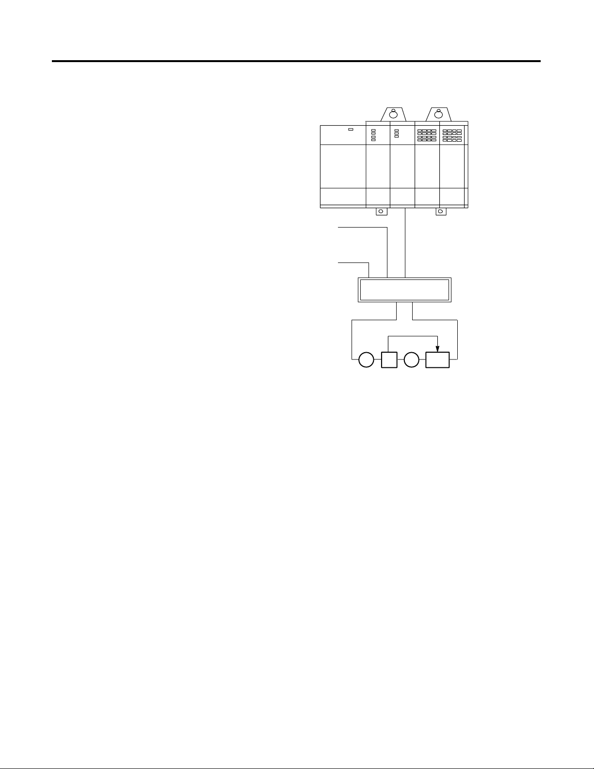
Figure 1.1 Example of an SLC Wiring
SLC Servo Module
Operation
1746IW16
Drive
Amplifier
CR-LPS-0503
+5V & –12V DC
Power Supply
CR-IOPS-241
+24V DC
Power Supply
SLC
5/04
A-B 845
Encoder
1746HSRV
1746-HCA Cable
1746-HT
Termination Panel
Motor
Tach
The SLC Servo Module, compatible with the SLC family, is used with
SLC 5/03 FRN 5.0 (and above) processors using RSLogix 500, AI500 or
APS (version 5.0 or higher) software. Once the SLC processor is
initiated, the execution of the motion block is independent of the scan
time of the processor. Blended motion allows for complicated move
profiles consisting of two to thirty-two segments. The blended move
profiles are stored in the SLC Servo Module’s memory as a series of
absolute moves and can be executed more than once. Other move or
homing operations can be performed between blended move profiles.
Publication 1746-6.1.2 - July 2000
The SLC Servo Module controls absolute position over a range of
32
bits. The SLC Servo Module performs an origin search (also called
homing) and automatically resets the absolute position to the home
position when the SLC processor requests a search function after
detecting one of the following:
• Encoder marker
• Limit switch
• Limit switch and marker
Page 22

Overview of the SLC Servo Module
The SLC Servo Module operates in two modes:
• Configuration
• Command
When operating in the configuration or the command mode, the status
of the module is reported to the SLC processor.
1-3
Configuration Mode Operation
You can enter configuration mode only if the system is in Estop. In the
SLC Servo Module, you configure the SLC Servo Module by using M
files containing data provided by the SLC 5/03 (or versions listed
above) processors. All configuration parameters are internal to the SLC
Servo Module and stored in non-battery backed RAM.
In configuration mode, you select the proper setup configuration to
match the servo drive and motor without setting switches and without
special software. If you do not set up your own configuration, the
configuration is set to the default setting.
Command Mode Operation
Motor operations are performed in command mode. To operate in this
mode, set the mode flag (bit 15 in output word 0) to 0. In the
command mode, the SLC processor issues commands and activates
the following operations or moves:
• Absolute moves
• Incremental moves
• Speed moves
• Monitor moves
• Hold moves
• Unhold moves
• Blend moves
• Emergency stop operations
• Homing operations
• Preset operations
• Clear faults
• Alternate home moves
Publication 1746-6.1.2 - July 2000
Page 23

1-4
Overview of the SLC Servo Module
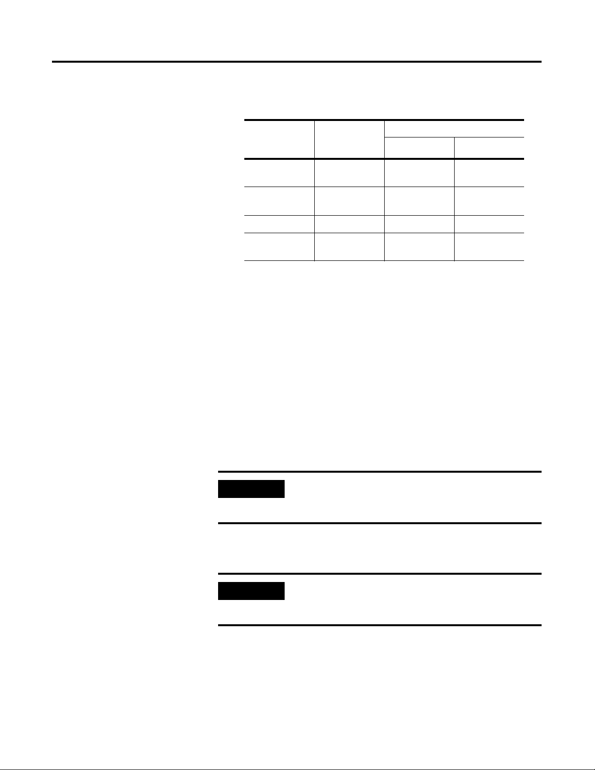
SLC Servo Module
Specifications and
Compatibility
Selected specifications for the SLC Servo Module appear in the table
below.
SLC Servo Module Specification
Class 3
Number of Input
Words
Number of Output
Words
Selection for
Configuration
Configuration Mode Uses M files
Recommended I/O
Slot in SLC Rack
Number of HSRVs in
one rack
1
There must not be other modules that generate module interrupts. Also, the STI and FAULT routines execute at a
higher priority than the module interrupt routine that is linked to the SLC Servo Module interrupt.
2
The SLC Servo Module does not function in a remote I/O rack.
12
12
OTHER
(with 10114 as the number specified)
Slot 1 or the lowest numbered I/O slot for SLC
applications using the module interrupt option.
12
with proper power supply
1,2
The SLC Servo Module is compatible with:
• SLC 5/03 FRN 5.0 (and above) processors.
• RSLogix 500, AI500, or APS (version 5.0 or higher) software.
Publication 1746-6.1.2 - July 2000
Page 24

Chapter
Selecting Power Supplies, Encoders, and
Drives
2
Overview
In this chapter we explain how to select the hardware you need to
support an SLC Servo Module system. This chapter includes the
following topics:
• Selecting a power supply for the backplane
• Selecting a user-side power supply
• Using fast inputs and outputs
• Selecting an encoder
• Selecting a drive
The amount of hardware you need depends on how many axes your
application uses. Consult your local Allen-Bradley sales engineer or
distributor to help you select the equipment for your application.
IMPORTANT
The term user-side refers to the control circuitry on
the SLC Servo Module card that is powered by
customer-supplied power sources and isolated from
the control circuitry that is powered by the
backplane of an SLC rack.
Selecting a Power Supply
for the Backplane
1 Publication 1746-6.1.2 - July 2000
Before you select a power supply, calculate the current requirements
for your backplane. Use the table below for SLC Servo Module
backplane current requirements:
Voltage Current Requirement
+5V .300A
+24V .104A
In your calculations, include the current requirements of the I/O
modules in your chassis. Refer to your SLC 500 documentation.
Page 25

2-2
Selecting Power Supplies, Encoders, and Drives
Example of Calculations for Backplane Current Requirements
In this example, the system includes:
• One seven-slot modular rack
• One 1747-L543 CPU module
• One 1746-IB8 DC input module with eight inputs @ +24V
• One 1746-OV8 DC output module with eight outputs @ +24V
• An SLC Servo Module system that contains:
• SLC Servo Modules
• Termination panels
• Allen-Bradley 845H encoders
• Fast inputs
• Fast outputs
Use the table below to find the current requirements of the devices
using backplane power. Those devices that are not included in the
backplane calculations are included in the example’s user-side
calculations.
Device +5V +24V
1746-L543 processor 1A .200A
SLC Servo Module .300A 0
1746-IB8 .040A 0
1746-OV8 .125A 0
Total = 1.465A Total = .200A
If optional processor is used:
Device +5V +24V
1747-L532 processor .500A .175A
SLC Servo Module .300A 0
1746-IB8 .040A 0
1746-OV8 .125A 0
Total = .965A Total = .175A
Publication 1746-6.1.2 - July 2000
Page 26
Selecting Power Supplies, Encoders, and Drives
2-3
Use the table below to find the power supplies Allen-Bradley recommends
for the backplane:
Selecting a User-Side
Power Supply
Power Supply Operating
Voltage
Requirements
1746-P1 85-130V AC or
170-265V AC
1746-P2 85-130V AC or
170-265V AC
1746-P3 19.2-28.8 DC 3.6A .87A
1746-P4 85-132V AC or
170-265V AC
Output Capacity
5V DC 24V DC
2A .46A
5A .96A
10.0A 2.88A
You must provide a power supply that meets your system
requirements. The following devices require user-side power:
• SLC Servo Module
• Encoders
• I/O modules
• Estop circuitry
• Fast inputs and outputs
You must select a power supply that meets the specifications of a NEC
class 2 power supply. The power supply must have +5V, ±15V
capacity, and +24V capacity for fast I/O and Estop circuitry.
IMPORTANT
We recommend that you do not use the +24V
included with the 1746-P1, P2, P3, or P4 to power
your Estop or fast I/O.
Before you select a power supply, calculate the system’s user-side
current requirements.
IMPORTANT
The user-side power must be present for the SLC
processor to communicate with the SLC Servo
Module.
Publication 1746-6.1.2 - July 2000
Page 27

2-4
Selecting Power Supplies, Encoders, and Drives
Example of the Calculations for User-Side Current Requirements
In this example, the system includes:
• One seven-slot modular rack
• One 1747-L541 CPU module
• One 1746-IB8 DC input module with eight inputs @ +24V
• One 1746-OV8 DC output module with eight outputs @ +24V
• An SLC Servo Module system that contains:
• Two SLC Servo Modules
• Two termination panels
• Two Allen-Bradley 845H encoders
• Six fast inputs
• Two fast outputs
Use the table below to find the current requirements of the devices
that draw user-side power.
Using Fast Inputs and
Outputs
Device +5V +15V –15V +24V
1746-IB8 0 0 0 .064A
1746-OV8 0 0 0 .800A
SLC Servo
Module
Estop circuitry 0 0 0 .100A
6 fast inputs 0 0 0 .015A
2 fast outputs 0 0 0 .100A
845H encoder .200A 0 0 0
845H encoder .200A 0 0 0
.150A .030A .030A 0
Total = .700A Total = .060A Total = .060A Total = 1.079A
The fast I/O (FIN1through FIN3, and FOUT1) are 24V DC compatible
and are used with a user-side +24V power supply. Review potential
Publication 1746-6.1.2 - July 2000
Page 28

Selecting Power Supplies, Encoders, and Drives
2-5
24V DC I/O devices for compatibility with the electrical specifications
as shown in the table below.
Outputs (source drivers)
Specification Rating
oh
V
(high-level, on-state output
voltage)
oh
I
(high-level, on-state output current
for each output)
Turn on time 500 µs
Turn off time 500 µs
Inputs
Specification Rating
VT (input low/high trip threshold) 10.51V (min)
VT (input high/low trip threshold) 6.4V (min)
HYST
V
IN
I
@ 27V 2.5 mA (max)
PD+
T
(input low/high debounce filter) .2 msec (typ)
PD-
T
(input low/high debounce filter) .2 msec (typ)
VIN (absolute max.) +75V (max)
Refer to the specifications for your
user-side power supply
+24V @ .20A (for resistive and
inductive loads); +24V @ .10A (for
capacitive loads)
12.5V (typ)
14.61V (max)
8.3V (typ)
10.3V (max)
1.9V (min)
4.1V (typ)
6.5V (max)
Selecting an Encoder
The SLC Servo Module system supports Allen-Bradley 845H encoders.
Other encoders are compatible if they comply with the specifications
listed in the following table.
Publication 1746-6.1.2 - July 2000
Page 29

2-6
Selecting Power Supplies, Encoders, and Drives
Specification Rating
Maximum
channel
frequency
Maximum axis
speed
Incoming quadrature frequency is limited by the following
relationship:
FQUAD (Hz) = (3334)(90°–EQ)
where:
EQ = quadrature error (degrees, electrical)
For example, for an 845H encoder with 22° quadrature error,
the maximum frequency would be:
FQUAD (Hz) = (3334)(90°-22° quadrature error) = 226,712 Hz
Important:
The maximum quadrature error is a limit, and
system design should include acceptable margins.
The SLC Servo Module decodes the incoming encoder
feedback in quadrature to extract the maximum resolution with
four counts per electrical cycle. The maximum number of
encoder counts per second can be determined by:
Maximum # of counts/second = 4 counts/cycle × F
QUAD
The maximum axis speed as limited by the encoder feedback
would be:
(maximum # of counts/second)(60)
(4E)(N)
where:
E = the number of encoder lines per revolution
N = number of revolutions of the encoder per inch or millimeter
of axis travel. (For a rotary axis, N = number of revolutions of
the encoder per revolution of the axis.) For a linear axis the
units are inches or millimeters per minute. For a rotary axis the
units are revolutions per minute.
Publication 1746-6.1.2 - July 2000
Input signal Encoder feedback must be differential with 5V compatible
output signals, open-collector outputs are not supported (i.e.,
channels A, B, and Z must have source and sink current
capability, 8830 line driver outputs or equivalent). The encoder
input must have a 0.00 to 0.80 for off state and 4.75 to 5.25 for
on state to encoder common reference.
Input sink current 7 mA (max)
Marker channel Gated markers
Cable length Depends on the user-side power supply. Power voltage at the
encoder must be greater than or equal to the power voltage
requirement specified by the manufacturer. The minimum
power requirement for the 845H is 4.75V, and the maximum
limit is 5.25V. To meet the power requirement of the encoder
and still attain maximum cable length, you can:
Raise the voltage of the power supply to meet the
•
encoder requirement, but you cannot exceed the 5.25V
limit of the control.
Increase the gage of the wire from the termination
•
panel to the encoder (12 AWG maximum).
Page 30

Selecting Power Supplies, Encoders, and Drives
2-7
Selecting a Drive
The SLC Servo Module supports Allen-Bradley 1386, 1388, 1389, 1391,
1392, 1394, and 1398 servo drive systems. References that help you
select a suitable drive system appear in the table below.
Allen-Bradley
Drive
1386 1386-2.0 DC Servo Drive Product Data Sheet
1388 1388-2.0 DC PWM Servo Drive Product Data Series B
1389 1389-2.0 AC Servo Amplifier System Product Data
1391 1391-2.0 AC PWM Servo Controller Product Data
1392 1392-2.1 High Performance AC Drive (460V and 230V)
1394 1394-2.0 1394 Digital Multi-Axis Motion Control
1398 1398-2.0 ULTRA Series Product Data
Publication
Number
Title
Sheet
Sheet
Product Data
Systems Product Data
The SLC Servo Module provides a ±10V analog output to one drive
amplifier for a velocity command. This analog voltage is 11 bits plus
an additional sign bit (12 bits total) and interfaces to drive amplifiers
with a 2K through 20K ohm range. Servo drive signal analog out
specifications appear in the table below.
Specification Rating
Resolution 12 bits or 4.88 mV/bit
Output voltage swing ±10V
Load range
Conversion time 100 µs
Output step response (20V
swing)
Differential linearity ±1 LSB Max. (monotonic over the entire
Output offset voltage 500 µV (max)
Gain error drift
Rise time
•
Overshoot
•
Settling time
•
2K through 20K ohms
110 µs typical
5% typical
60µs typical
temperature range)
7 LSB (max)
Publication 1746-6.1.2 - July 2000
Page 31

2-8
Selecting Power Supplies, Encoders, and Drives
Publication 1746-6.1.2 - July 2000
Page 32

Chapter
3
Planning Hardware Installation
This chapter provides guidelines regarding your hardware installation
and includes the following topics:
• Understanding general wiring practices
• Routing wires
• Classifying your conductors
• Placing your SLC Servo Module
Refer to your SLC 500 documentation for more information on these
topics.
General Wiring Practices
General wiring practices include:
• Using shielded cables
• Routing wires
Using Shielded Cables
For many connections, we recommend shielded cable. Using shielded
cables and properly connecting their shields to ground protects
against electromagnetic noise interfering with signals transmitted
through the cables.
ATTENTION
To avoid personal injury or equipment damage
caused by unpredictable axis motion in your system,
use shielded cable as directed in this manual.
!
Within a cable, pairs of wires are twisted together. Using a twisted pair
for a signal and its return path provides further protection against
noise.
Shield wires should be terminated at one end only. The termination
panel is a convenient place to connect all shield wires while providing
the necessary ground connection.
1 Publication 1746-6.1.2 - July 2000
Page 33

3-2
Planning Hardware Installation
Cut the shield wires on the opposite end at the cable jacket and tape it
to prevent contact with ground. We also recommend keeping the
length of leads that extend beyond the shield as short as possible.
In high noise environments, you connect shield wires at both ends of
the cable to improve the noise immunity of the system. If this is done,
terminate one end of the shield to ground through a 0.1 µf capacitor
to avoid ground loops in the system.
Routing Wires
When you plan your wire route, classify wires and cables connecting
your SLC Servo Module system using the information in this table.
The table also tells you how to classify conductors and route cables.
IMPORTANT
Remember to keep low-level signal conductors
separate from high-level power conductors.
Follow the practices outlined in Programmable Controller Wiring and
Grounding Guideline (publication 1770-4.1) to learn how to route
other conductors.
Publication 1746-6.1.2 - July 2000
Page 34

Planning Hardware Installation
3-3
Classifying Your
Conductors
For these wires
and cables:
AC power lines
SLC Servo Module cable
(1746-HCA) and
termination panel wiring
Use the table below for cable routing guidelines and determining wire
and cable functions.
To : Follow these guidelines for routing inside or
outside an enclosure:
Connect high-power AC I/O lines to AC I/O
•
modules that are rated for high power and
high noise immunity.
Connect high-power DC I/O lines to DC I/O
•
modules that are rated for high power or
have input circuits with long time constant
filters for high noise rejection. They typically
connect to devices such as hard-contact
switches, relays, and solenoids.
Connect serial communication cables to
•
programming terminals or data terminals,
and connect them from the scanner to
remote I/O adapter modules or PLC
processors.
Connect low-power AC/DC I/O lines to I/O
•
modules that are rated for low power such
as low-power contact-output modules.
Connect low-power DC I/O lines to DC I/O
•
modules that are rated for low power and
have input circuits with short time constant
filters to detect short pulses. They typically
connect to devices such as proximity
switches, photo-electric sensors, TTL
devices, encoders, motion control devices,
and analog devices.
Route these high-power AC lines with machine
•
power conductors of up to 600V AC (feeding up
to 100 hp devices) if this does not violate local
codes.
Article 300-3 of the National Electrical Code
•
requires that all conductors (AC and/or DC) in
the same raceway are insulated for the highest
voltage applied to any one of the conductors in
the raceway.
Properly shield conductors, where applicable,
•
and route them in separate raceways. If
conductors must cross power feed lines, they
should do so at right angles.
Route these lines at least 1 foot from 110V AC
•
power lines, 2 feet from 240V AC power lines,
and 3 feet from 480V AC power lines.
Route these lines at least 3 feet from any
•
electric motors, transformers, rectifiers,
generators, arc welders, induction furnaces, or
sources of microwave radiation.
If the conductor is in a metal raceway or
•
conduit, that raceway or conduit must be
grounded along its entire length.
Placing Your SLC Servo
Module
When you plan your SLC Servo Module placement:
• Divide modules, as much as possible, into the following types:
AC
•
High-level DC
•
Low-level digital DC (TTL, encoder, pulse output)
•
Analog I/O
•
Intelligent I/O modules (for example, the SLC Servo Module)
•
• Place the SLC Servo Module as close to the SLC processor as
possible.
• Keep your SLC Servo Module as far away as possible from DC
and AC I/O modules. Distance protects the intelligent
(CPU-based) modules from the heat and electrical noise of the
DC and AC I/O modules.
Publication 1746-6.1.2 - July 2000
Page 35

3-4
Planning Hardware Installation
Place the SLC Servo Module on the left side of the chassis along
•
with other in telligent I/O modules and the CPU.
Place DC and AC I/O modules on the right side of the chassis and
•
allow empty slots to remain between them and the SLC Servo
Module.
Publication 1746-6.1.2 - July 2000
Page 36

Chapter
4
Installing Your SLC Servo Module
This chapter provides guidelines for installing your SLC Servo Module
and includes the following topics:
• Unpacking and inspecting the SLC Servo Module system
• Installing the SLC Servo Module
• Grounding the SLC Servo Module
• Mounting the termination panel
• Connecting the termination panel
Unpacking and Inspecting
Your SLC Servo Module
System
ATTENTION
!
Before removing the contents from the shipping
carton, avoid electrostatic discharge that degrades
performances and damages the module by doing the
following:
• Touch a grounded object to eliminate static
charge from your body before handling the
module.
• Wear a wrist strap (for example, catalog number
8000-XESD) that provides a high-resistance path
to ground.
• Keep the module in its static-shield bag when not
in use.
For more information about electrostatic discharge
and how to guard against it, refer to Guarding
Against Electrostatic Damage - Using the ESD Kit
(publication 8000-4.5.2).
1 Publication 1746-6.1.2 - July 2000
Page 37

4-2
Installing Your SLC Servo Module
To verify that you received what you ordered:
1. Check the label on each shipping carton with your order.
2. Check the items received against the bill of lading by matching
the equipment nameplate description with the material ordered.
Installing the SLC Servo
Module
IMPORTANT
Make claims for breakage and damage, whether
concealed or obvious, to the carrier as soon as
possible after receipt of the shipment. Allen-Bradley
gives the buyer reasonable assistance in securing
adjustment for damage claims.
The first component you install is the SLC Servo Module. After
installation, you connect the other components.
Figure 4.1 SLC Servo Module with Door Open
RUN
FDBK/U. PWR
Not used
To Termination Panel
CONFIG INV
Publication 1746-6.1.2 - July 2000
Note: The two switches on back are not used.
The table below provides a legend for the SLC Servo Module LEDs.
When: This LED is on:
Power is applied RUN
The feedback signal or user-side
power is lost
FDBK/U.PWR
Page 38

When: This LED is on:
Installing Your SLC Servo Module
4-3
An invalid configuration is
detected
ATTENTION
To avoid personal injury, equipment damage, or
performance degradation, remove backplane power
from the chassis and disconnect the 1746-HCA cable
before installing or removing a module.
!
ATTENTION
To avoid damage to a module or backplane
connector, do not force modules into the backplane
connector.
!
CONFIG INV
To insert a module into an I/O chassis:
1. Remove backplane power from the I/O chassis.
2. Remove user-side power from the SLC Servo Module.
3. Disconnect the 1746-HCA cable.
4. Align the larger of the two boards of the SLC Servo Module with
the card-edge guide at the bottom of the chassis.
5. Slide the module into the chassis.
6. Press the module firmly to seat it into the backplane connector.
7. Verify that the locking latches on the top and bottom of the
chassis hold the module in place.
IMPORTANT
The term user-side refers to the control circuitry on
the SLC Servo Module card that is powered by
customer-supplied power sources and isolated from
the control circuitry that is powered by the
backplane of an SLC rack.
Publication 1746-6.1.2 - July 2000
Page 39

4-4
Installing Your SLC Servo Module
Grounding the SLC Servo
Module
Control Module
Backplane
B
Side
a
c
k
p
l
a
n
e
Earth ground
through backplane
Isolated
User
Side
Axis
Overall
cable shield
Before you install the rest of the system, you must ground the SLC
Servo Module. All of the shields and signal commons (normally
floating) are tied to earth ground at a single point. Use the EGND
terminal on the termination panel for this purpose.
IMPORTANT
Do not connect shields to earth ground at both ends
to avoid causing circuit loops that are susceptible to
radiated and coupled noise.
Figure 4.2 Typical Grounding and Shielding for the SLC Servo Module System
1746-HCA cable
Twisted
pair (x10)
Shielded
twisted
pair (x3)
Optional
EGND
Termination panel
Axis
External power
+24V
RET
see ATTENTION
User-supplied shielded cable
Drive CMD
Drive
Channel A
Encoder
Channel B
Channel Z
Encoder PWR
User-side power supply
ATTENTION
!
+5V
–15V
RET
To avoid unpredictable operation of your SLC Servo
Module use a separate +24V power supply and tie
the +24V return to the +5V return. (The +5V, +15V,
and -15V returns are tied together on the SLC Servo
Module.)
Publication 1746-6.1.2 - July 2000
Page 40

Installing Your SLC Servo Module
4-5
Mounting the Termination
Panel
Refer to the Figure 4.3 and Figure 4.4 when mounting the 1746HT
termination panel.
To mount the 1746HT termination panel:
1. Snap the termination panel onto the DIN-type rail (1492-DR2).
2. Position an end anchor on either end of the termination panel.
3. Secure the panel by tightening the end anchor screws.
The end anchor prevents the termination panel from sliding in either
direction on the DIN rail.
Figure 4.3 Mounting the Termination Panel
DIN Rail
End Anchor & Screw
DRIVE
DRIVE
DR RET
SHLD
ENCODER
CH A.HI
CH A. LO
AB SHLD
CH B.HI
CH B. LO
ZSHLD
CH Z. HI
CH Z. LO
ENCODER POWER
Termination Panel
Publication 1746-6.1.2 - July 2000
Page 41

4-6
Installing Your SLC Servo Module
Figure 4.4 Termination Panel and its Dimensions
DRIVE
DRIVE
DR RET
SHLD
ENCODER
CH A.HI
CH A. LO
AB SHLD
CH B.HI
CH B. LO
ZSHLD
CH Z. HI
CH Z. LO
ENCODER POWER
+5V
RET
+15V
SHLD
EXT POWER
+5V
RET
+15V
_
+
RET
-15V
+24
+24 R E T
EGND
AXIS
292mm
(11.5 in.)
DRIVE ENABLE
ESTOP
+24
V
RES.PB
RES.PB
RESET
STRING IN
STRING OUT
FAST I/O
FI.1
V
+24
FI.2
+24
FI.3
RET
FO.1
1746HT R EV0 1
TE RMIN A TION P A N EL
70mm
(2.75 in.)
89mm
(3.5 in.)
Publication 1746-6.1.2 - July 2000
Page 42

Installing Your SLC Servo Module
4-7
Connecting the Termination
Panel
After mounting the termination panel, connect it to the SLC Servo
Module with the 1746-HCA cable. To connect the termination panel to
the SLC Servo Module:
1. Set the locking latches above and below the connector so the
latch reads OPEN.
2. Open the door of the SLC Servo Module.
3. Hold the connector as shown in Figure 4.5 (left) and insert it
into the D-sub connector on the SLC Servo Module until the
connector is seated.
4. Insert a small, flat-edge screwdriver next to the locking latch
located between the module door and connector.
5. Slide the locking latch to the right with your screwdriver.
6. Insert the small, flat-edge screwdriver next to the locking latch
located between the module door and connector.
7. Slide the locking latch to the left with your screwdriver.
8. Connect the other end of the cable to the 1746-HT termination
panel, as shown in Figure 4.5 (right).
Publication 1746-6.1.2 - July 2000
Page 43

4-8
Installing Your SLC Servo Module
Figure 4.5 Connecting the 1746-HCA-Cable
Connecting to the
1746-HSRV
1746-HCA
Cable
Connecting to the
1746-HT
EN
OP
1746-HCA
Cable
Publication 1746-6.1.2 - July 2000
Page 44

Wiring the SLC Servo Module
Chapter
5
Overview
Complying with European
Union Directives
After mounting and connecting the termination panel, you wire fast
inputs, outputs, and your Estop string to the termination panel when
you wire the system power supply, encoders, and drives. This chapter
includes the following topics:
• Complying with European Union directives
• Wiring fast inputs and outputs
• Wiring hardware overtravels
• Connecting home limit switch as a fast input
• Wiring Estop connections
• Wiring power supplies
• Wiring encoders
• Wiring Allen-Bradley drive connections
• Connecting the velocity command
If this product is installed within the European Union or EEA regions
and has the CE mark, the following regulations apply.
EMC Directive
If this apparatus is tested to meet Council Directive 89/336
Electromagnetic Compatibility (EMC) in accordance with Article 10
(1), the following standards apply in whole:
• EN 50081-2 EMC-Generic Emission Standard, Part 2-Industrial
Environment
• EN 50082-2 EMC-Generic Immunity Standard, Part 2-Industrial
Environment
The product described in this document is intended for use in an
industrial environment and is not intended for use in a residential,
commercial or light industrial environment.
IMPORTANT
1 Publication 1746-6.1.2 - July 2000
To meet CE requirements, you must use the specified
Allen-Bradley cables and termination panel for the
SLC Servo Module (catalog number 1746-HSRV).
Page 45

5-2
Wiring the SLC Servo Module
Wiring Fast Inputs and
Outputs
On the termination panel, the +24V DC fast inputs and outputs of the
SLC Servo Module are routed from the connector (37-pin D-shell) to
the fast I/O connector (7-pin pluggable) on the termination panel.
The fast I/O consists of:
• Fast inputs FI.1 through FI.3
• Fast output FO.1
• +24V DC and +24V DC return signals
We recommend 18 AWG wire for wiring fast I/O because it allows two
wires for each connection point. The termination panel accepts 12
AWG wire, but this allows only one wire per point.
Figure 5.1 shows a diagram of typical fast I/O connections. For
electrical dampening, a snubber is required to filter out electrical
spikes. The snubber is used for inductive and comparative loads on
the fast output.
Figure 5.2 and Figure 5.3 shows equivalent fast input and output
circuits.
IMPORTANT
The input device must connect between +24V DC
and the appropriate fast input. Fast inputs are +24V
DC referenced. The fast output is ground-referenced.
The output load must connect between the fast
output and ground.
Publication 1746-6.1.2 - July 2000
Page 46

14 AWG
Electrical Cabinet
GND
Figure 5.1 Typical Fast I/O Connections
ESTOP
+24
RES.PB
RES.PB
RESET
STRING IN
STRING OUT
FAST I/O
FI.1
+24V
FI.2
+24V
FI.3
RET
FO.1
GND
Wiring the SLC Servo Module
5-3
Snubbing is required for inductive and
capacitive loads on the fast output.
Capacitive load
Current limiting resistor required. Must
be placed in series with contact load.
RET
FO.1
18173
Publication 1746-6.1.2 - July 2000
Page 47

5-4
Wiring the SLC Servo Module
Figure 5.2 Equivalent Fast Input Circuit
+24V D C
W
15K
47K
W
1746-HCA
11K
W
Control
Module
Termination
Panel
Figure 5.3 Equivalent Fast Output Circuit
1746-HCA
Control
Module
+5V DC
Termination
Panel
K2
Ret
V
+24 DC
FO.1
Wiring Hardware
Overtravels
Publication 1746-6.1.2 - July 2000
Because the system must go into Estop when a hardware overtravel is
tripped, do the following to the hardware overtravel limit switches of
each axis:
• Wire them into the customer Estop string.
• Position them outside the software overtravels (see Figure 5.4).
Page 48

Wiring the SLC Servo Module
Software Overtravel Limits
Software overtravel limits appear in the table below.
Name What it specifies Default Range
5-5
Software overtravels used Whether control checks
software overtravel limits
Yes Yes (used) or
No (not used)
When you are using a check, the SLC Servo Module tests each
program for motion past an overtravel limit before the programmed
motion is executed.
The SLC Servo Module monitors software overtravel limits
continuously during motion. Software overtravels are disabled during
homing and are not active until the axis is homed. Software overtravel
limits are located inside hardware overtravel limits. Hardware
overtravel limits cause Estop when tripped.
Figure 5.4 Software Overtravel Limits
-+
Negative Overtravel Limit
W10-W11
0
Positive Overtravel Limit
W8-W9
Connecting Home Limit
Switch as a Fast Input
Negative Hardware Overtravel Limit
(causes Estop)
IMPORTANT
Check positive and negative software and hardware
overtravel limits only if Overtravels Used (word 0, bit
Positive Hardware Overtravel Limit
(causes Estop)
7) is set.
You can configure the home limit switch to come from the termination
panel, or from the backplane by setting configuration word 1, bit 0.
The 1 represents termination panel Fast Input 3. The 0 represents
Publication 1746-6.1.2 - July 2000
Page 49

5-6
Wiring the SLC Servo Module
backplane input. Though the exact position of home is not important,
it is important that the home position is:
• A repeatable resting place for the axis when it is not used.
• Free of obstruction from another moving axis.
To connect a home limit switch:
1. Place the limit switch near the home position that you want.
2. Adjust the encoder so that the marker is approximately 1/2
revolution from the limit switch closure.
Wiring Estop Connections
IMPORTANT
If you do not adjust the encoder, home can be off by
one encoder revolution.
The SLC Servo Module detects and controls Estop conditions. Each
SLC Servo Module has a separate and independent Estop circuit. Refer
to the documentation that came with your drive for recommendations
on correctly wiring your external Estop string.
A hardware Estop is caused by the following:
• Broken wire in the user power cable.
• Power-fail signal from chassis backplane.
• Watch-dog time-out on SLC Servo Module.
• Software Estop conditions.
• A contact in the external Estop string or a broken/missing wire
opens the string (e.g., when someone pushes the Estop push
button).
Specifications for Estop relay on the SLC Servo Module appear in the
table below.
Publication 1746-6.1.2 - July 2000
Specification Rating
Maximum contact voltage rating 80V DC max
Operate time 500µs average
Contact bounce less than 200µs average
Contact resistance 150 milliohms average
Contact rating 5.0VA @ 0.35A max
Page 50

Wiring the SLC Servo Module
Wiring the Estop for a One-Axis System
To wire the Estop for a one-axis system connect the following:
• Drive enable
• Estop reset pushbuttons (Res P.B., Res P.B., and Reset)
• Customer Estop String (String In and String Out)
5-7
ATTENTION
To avoid personal injury or hardware damage,
develop a fail-safe wiring design for your Estop
string.
!
• An Estop string (Figure 5.5) is connected in series and consists
of:
• Axis hardware overtravels
• Remote Estop
• Motor thermal switch
• Transformer thermal switch
• Drive fault
Wiring for Normal Operation
• Wire the Estop inputs for normal operation.
• Bench test your SLC Servo Modules.
• The Estop Reset pushbutton requires a two-pole single-throw
switch.
Maintaining Electrical Continuity
• Maintain electrical continuity on the termination panel between
the String Out and String In terminals to change from an Estop
state to a run state when pressing the Estop Reset pushbutton.
• While in the run state, loss of continuity between String Out and
String In places the SLC Servo Module in an Estop state.
• All motion is inhibited in the Estop state.
Verifying Connections and Operation
• Verify that the Estop wiring is connected correctly.
• Check the operation of devices wired between String Out and
String In.
Publication 1746-6.1.2 - July 2000
Page 51

5-8
Wiring the SLC Servo Module
Figure 5.5 Ladder Diagram for a One-Axis System
+24V DC
CR1-1
CR1-4
P2-9
Estop
Res. P.B.
P2-8
Reset
To Estop Status
on Control Module
Control Module
P2-7
To Estop Reset Request
on Control Module
P2-6
String Out String In
Customer
Estop
String
+24V D C Ret.
CR1
1N 4001
CR1-2
CR1-3
IMPORTANT
In this equivalent Estop circuit, P2 is a 25-pin D-shell
connector.
CR1-2 and CR1-3 are auxiliary contacts of CR1 used
in the drive interface. Use them for the drive enable
of each drive amplifier. CR1-3 is not always required.
For more information, see the drawings that
accompany your drive.
Specifications for the CR1 (Allen-Bradley P/N 700-HC 14Z24) appear
in the table below.
CR1 Part Number Coil Contact Arrangement
700-HC 14Z24 24V DC, 650 ohms 3A Resistive, 120V AC4 form C
Publication 1746-6.1.2 - July 2000
Page 52

8
6
7
9
Control
Module
Estop
Reset
Request
Control Module
Estop
Contacts
Estop
Status
25-Pin D-Shell Connector
+24V
CR 1-4
CR 1-2
CR 1-3
CR 1
CR 1-1
Res.
P.B.
Res.
P.B.
Termination
Panel
String
Out
String
In
Reset
+24V
To Customer Drive
Enable Circuit
String Pilot
Cr 2-1
Estop
Reset P.B.
(Customer-Supplied)
Refer to Figure 4.1 for
Shield Connections
Cable Length Must
Not Exceed 10 m (32 feet)
Wiring the SLC Servo Module
5-9
ATTENTION
If you do not use the relay shown in Figure 5.8,
verify that your replacement relay has a coil
resistance greater than or equal to 650 ohms.
!
Figure 5.6 Estop Circuitry Diagram for a One-Axis System
Publication 1746-6.1.2 - July 2000
Page 53

5-10
Wiring the SLC Servo Module
Figure 5.7 String Pilot Connection
Drive Fault
Contact Overtravel
Customer
-
EstopString
Thermal
Overload
Remote
E-Stop
CR2
String Pilot
To wire Estop connections, refer to wiring diagrams for the drive you
are using. The wiring of six different Allen-Bradley compatible drives
is shown in the table below.
Figure Wiring Diagram
5.15 1386 DC Servo Drive
5.16 1388 DC PWM Servo Control
5.17, 5.18
1389 AC Servo Amplifier
5.19, 5.20 1391 AC Servo Control Module Amplifier
5.21 1392 AC Servo Amplifier
5.22, 5.22 1394 AC Servo Control Module Amplifier
1
5.24
5.25
1398 ULTRA 100™/200™ Series AC Servo Control
Module Amplifiers
5.26
1
The 1389 servo drive requires a 115V AC power conductor (K1) to supply main power to the
drive amplifier. See the 1389 Servo Amplifier Installation Manual for details
Wiring the Estop for System with Two or More Axes
For a system with two or more axes, you must have a termination
panel and a SLC Servo Module for each axis. See Figure 5.8 and Figure
5.9 for the ladder diagram and Estop circuitry diagram for these
systems.
The Estop characteristics for this type of system are:
• SLC Servo Modules must be running before the system comes
out of Estop.
• If an axis drops into Estop, the system drops into Estop.
The power capacity of the user-supplied +24V DC power supply
determines the number of axes on one Estop string. Each Estop string
requires ~ 50 mA of current from the +24V supply.
Publication 1746-6.1.2 - July 2000
Page 54

Wiring the SLC Servo Module
Figure 5.8 Ladder Diagram for a Two-Axes or Three-Axes System
5-11
+24V D C
CR3-1
CR1-4
CR2-4
CR3-4
Control
Module #1
P2-6 P2-6 P2-6
P2-7
To P2-8 Control Module #1
To P2-8 Control Module #2
To P2-8 Control Module #3
To P2 Control Module #1 Estop status P2-9
To P2 Control Module #2 Estop status P2-9
To P2 Control Module #3 Estop status P2-9
Control
Module #2
Estop Reset
Request
+24V DC
Return
Control
Module #3
String
Out
P2-7P2-7
Customer
Estop
String
String
In
CR1
CR2
CR3
IMPORTANT
P2 is the 25-pin D-shell connector on the SLC Servo
Modules.
Specifications for the CR1 (Allen-Bradley P/N 700-HC 14Z24) appear
in the table below.
CR1 Part Number Coil Contact Arrangement
700-HC 14Z24 24V DC, 650 ohms 3A Resistive, 120V AC4 form C
IMPORTANT
Use CR1, CR2, and CR3 auxiliary contacts for the
drive enable of each drive amplifier. CR2 and CR3
are not always required.
Publication 1746-6.1.2 - July 2000
Page 55

5-12
Wiring the SLC Servo Module
Figure 5.9 Estop Circuitry Diagram for a Two-Axes or Three-Axes System
Te rminatio n
Panel #1
Customer
Estop
String
Co ntrol Module #1
Estop
Control’s
Reset
Estop
Request
Contacts
8
67 9
String
CR1
String
Out
In
Reset
Res.
P.B.
CR1-1
Res.
P.B.
+24V
+24V
Estop
Status
CR1-2
25-pin D-shell
connector
CR1-4
CR1-3
To Drives
Termination
Panel #2
CR2
Co ntrol Module #2
Estop
Control’s
Reset
Estop
Request
Contacts
8
67 9
Res.
P.B.
CR2-1
String
In
String
Reset
Out
Res.
P.B.
+24V
Estop
Status
+24V
CR2-2 CR2-3
To Drives
25-pin D-shell
connector
CR2-4
Termination
Panel #3
CR3
Control Module #3
Estop
Control’s
Reset
Estop
Request
Contacts
8
67 9
Res.
P.B.
CR3-1
String
In
String
Reset
Out
Res.
P.B.
Estop
Status
+24V
+24V
CR3-2 CR3-3
25-pin
D-shell
connector
CR3-4
To Drives
Estop
Reset P.B.
(usersupplied)
Wiring Power Supplies
Figure 5.10 shows how to wire a power supply for backplane and
user-side requirements and a +24V power supply for Estop circuitry to
the termination panel.
Publication 1746-6.1.2 - July 2000
Page 56

L1
L2
+24V Power Supply
AC HI
AC LO
Figure 5.10 Wiring a +5V, ±15V, and a +24V Power Supply
+5V
+5V
+/- 15V
+24V R ET
COMM
+15V
COMM
-15V
+24V
14 AWG
14 AWG
14 AWG (3)
EXT POW ER
14 AWG
Wiring the SLC Servo Module
+5 V
RET
+15V
-/+RET
-15V
+2 4
+24R ET
EGND
5-13
AC Line
Wiring Encoders
Electrical Cabinet
Ground Bus
ATTENTION
To avoid unpredictable operation of your SLC Servo
Module, connect the +5V COMM to the +24V COMM.
If voltage sources are coming from two separate
isolated power supplies, tie the +24V return to the
!
+5V return.
When you wire encoders, use a single, continuous, shielded cable
segment. Wire the cable directly from the encoder to the termination
panel.
Cable length depends on the power supply for the user-side. Voltage
at the encoder must be within the voltage requirement limits specified
Publication 1746-6.1.2 - July 2000
Page 57

5-14
Wiring the SLC Servo Module
by the manufacturer. Those limits for the 845H are a minimum voltage
requirement of 4.75V and a maximum voltage of 5.25V.
IMPORTANT
The term user-side refers to the control circuitry on
the SLC Servo Module card that is powered by
user-supplied power sources and isolated from the
control circuitry powered by the backplane of an SLC
rack.
To meet the voltage requirement of the encoder and still attain
maximum cable length, you can do the following:
• Raise the voltage of the power supply to meet the encoder
requirement without exceeding the 5.25V limit of the SLC Servo
Module, measured at the module.
• Increase the gage of the wire connecting the termination panel
to the encoder (12 AWG maximum).
Figure 5.11 shows a circuit equivalent for channel A.
Figure 5.11 Encoder Feedback Equivalent Circuit
+5V
Differential
Line Driver
Customer
Encoder
768 ohms
+
-
768 ohms
0.01 microfarads
221 ohms
A
A
1746-HCA
Ch A HI
Ch A LO
+5V
Publication 1746-6.1.2 - July 2000
Control Module
Termination Panel
Page 58

Wiring the SLC Servo Module
5-15
To operate the encoder, wire the encoder so that marker Z is true at
the same time that A and B channels are true. To wire the encoder for
consistent homing of the axis, do the following:
1. Obtain the encoder output timing diagram from the vendor’s
data sheets. A typical example is shown in Figure 5.12.
2. On the timing diagram, look at marker Z and its complement,
marker Z
.
3. Determine which signal is low for most of the encoder
revolution and pulses high for the marker interval.
4. Wire the signal that was determined in Step 3 to CH Z.HI on the
termination panel.
5. Wire the other to CH Z.LO on the termination panel.
6. Look at channel B and its complement, channel B
.
7. Wire CH B.HI on the termination panel to the signal that is high
for at least part of the marker interval. Depending on the
encoder manufacturer, it is possible that both channels meet this
requirement. If so, use either one.
8. Wire the complementary remaining phase to CH B.LO on the
termination panel.
9. Look at channel A and its complement channel A
.
10. Wire the signal that is low for most of the encoder revolution
and pulses high for the marker interval to CH A.HI on the
termination panel.
11. Wire the complementary signal to CH A.LO on the termination
panel.
Typical Vendor Encoder Wiring
See your vendor’s encoder literature for the applicable timing
diagram.
Publication 1746-6.1.2 - July 2000
Page 59

5-16
Wiring the SLC Servo Module
Figure 5.12 Typical Vendor Encoder Timing Diagram
See 1 in table below
Optional
1cycle
90
Channel A
B
Z
A
B
Z
See 2 in table below
See 3 in table below
Hi
Lo
CCW rotation
viewing shaft
WireCH B, CH A,and CH Z to CHB LO,
CHA LO and CH Z LO, respectively,
on the termination panel.
Location: Shows:
1 Channel A is high for at least part of marker interval. You connect this
to CH A.HI of the termination panel.
2 High marker interval. You connect this to CH Z.HI of the termination
panel.
3 B is high for at least part of marker interval. You connect this to CH
B.HI of termination panel.
Encoder Feedback Direction
The encoder can spin either CW or CCW for a given table direction
and the direction (phasing) of the feedback could be backwards.
Publication 1746-6.1.2 - July 2000
You can change the direction of the feedback by switching channel A
wiring with channel B wiring. For encoder feedback connections, see
Figure 5.13 and 5.14.
Page 60

CH A.HI
CH A.LO
AB SHLD
CH B.HI
CH B.LO
ZSHLD
CH Z.HI
CH Z. LO
+5V
RET
+1 5 V
SHLD
Figure 5.13 5V Encoder Feedback Connections
ENCODER
ENCODER POWER
Wiring the SLC Servo Module
1
A
5-17
A
1
1
2
B
B
Z
Z
+5V
A
H
I
B
C
J
F
Optical
Encoder
D
3
G
Case
+5V
Return
Ground
CH A.HI
CH A.LO
AB SHLD
CH B.HI
CH B.LO
ZSHLD
CH Z.HI
CH Z. LO
+5V
RET
+1 5 V
SHLD
1
Use three pair 22 gauge individually twisted and shielded cable.
2
Use one pair 18 gauge twisted and shielded cable.
3
Encoders must have +5V compatible differential line drive outputs on channels A, B, and Z (DS 8830 or equivalent
Figure 5.14 15V Encoder Feedback Connections
ENCODER
ENCODER POWER
(845H)).
1
A
A
+15V
B
B
Z
Z
Return
A
H
I
B
C
J
F
Optical
Encoder
D
3
G
1
1
2
Case
Ground
+15V
1
Use three pair 22 gauge individually twisted and shielded cable.
2
Use one pair 18 gauge twisted and shielded cable.
3
Encoders must have +5V compatible differential line drive outputs on channels A, B, and Z (DS 8830 or equivalent
(845H)).
Publication 1746-6.1.2 - July 2000
Page 61

5-18
Wiring the SLC Servo Module
Wiring the SLC Servo to
Allen-Bradley Drives
The SLC Servo Module supports 1386, 1388, 1389, 1391, 1392, 1394,
and 1398 servo amplifiers. Before you wire the drive to the
termination panel, you must mount, set up, and wire your drive and
motor.
Installation references for each Allen-Bradley servo drive system
(amplifier) appear in the table below.
Allen-Bradley
Drive
1386 1386-5.0 Bulletin 1386 DC Servo Drive Instruction Manual
1388 1388-5.1 Bulletin 1388 DC PWM Servo Controller
1389 1389-5.0 Bulletin 1389 AC Servo Amplifier System
1391 1391-5.0 Bulletin 1391 AC Servo Controller User Manual
1392 1392-5.1 Bulletin 1392 High Performance AC Drive
1394 1394-5.0 1394 Digital AC Multi-Axis Motion Control
Publication
Number
Title
Instruction Manual
Operator Instructions
Instruction Manual
System
1398 ULTRA 100 1398-5.2 ULTRA 100 Series Drives Installation Manual
1398 ULTRA 200 1398-5.0 ULTRA 200 Series Drives Installation Manual
Information regarding how to wire Allen-Bradley drives to the
termination panel is given in the table below.
Drive Figure
1386 5.15,
1388 5.16,
1389 5.17, 5.18,
1391 5.19, 5.20,
1392 5.21,
1394 5.22, 5.23,
1398 5.24,
Wiring Diagram for 1386 Drives
Wiring Diagram for 1388 Drives
Wiring Diagram for 1389 Drives (2 parts)
Wiring Diagram for 1391 Drives (2 parts)
Wiring Diagram for 1392 Drives
Wiring Diagram for 1394 Drives (2 parts)
Wiring Diagram for ULTRA 100 When Not Homing to a Marker and
for ULTRA 200 When Homing to a Marker
5.25,
Wiring Diagram for F, H, and S series ULTRA 200 When Homing to a
Marker
5.26,
Wiring Diagram for Y series ULTRA 100/200 When Homing to a
Marker
Publication 1746-6.1.2 - July 2000
Page 62

Wiring the SLC Servo Module
5-19
+2 4V
RES.PB
RES.PB
RESET
STRING IN
STRING OUT
DRIVE
DR RET
SHLD
DRIVE ENABLE
ESTOP
DRIVE
ATTENTION
To avoid damage to the controller, connect these
lines in the proper phase at the transformer and
controller. These lines are phase sensitive.
!
Figure 5.15 Wiring Diagram for 1386 Drives
CR
2
Estop
Reset
P.B.
DROK
Board
TB1 -
1Diff+
2Diff3SignalCommon
4Aux
5Tach
6SignalCommon
TB2 -
1 Decoupled C urr
2SigCommon
3 R eset
4Interlock
5 Signal Clamp 6 Signal Clamp +
7 Signal Clamp R ef
J1
+ 15V DC
Common
- 15V DC
FAST I/O
RET
F01
See 1326-2.0 for encoder connection
and motor wiring.
CR
Axis Remote
Overtravel
Customer-supplied
Encoder
contingency
stop
1386 - A A Amplifier
1386 - M Cha ssis
Motor
Motor Power
Terminal Block
Publication 1746-6.1.2 - July 2000
Page 63

5-20
Wiring the SLC Servo Module
DRIVE
ENABLE
+2 4V
RES.PB
RES.PB
RESET
STRING IN
STRING OUT
ESTOP
Figure 5.16 Wiring Diagram for 1388 Drives
240/480V AC
3Phase
50/60Hz
Estop
Reset
P.B.
H1
H4
H7
Y1
Y2
Y3
Bulletin 1388
Power
Transformer
P1 P2
120V AC
3 phase
50/60Hz
X1
X2
X3
X0
G0
Thermal
Switch
DRIVE
DR
SHLD
DRI
RET
VE
Axis
Overtravel
T1
Velocity
Command
Remote
Estop
Tach
T2
A2
A3TB1
1
2
3
4
5
6
7
8
9
10
11
12
13
14
15
P1
M
Motor
+ 23V DC
A1
P2
45 789A2TB1
Bulletin 1388
DC Servo Controller
CR1
Drive
Fault
CR1
Publication 1746-6.1.2 - July 2000
Page 64

Figure 5.17 Wiring Diagram for 1389 Drives
System Ground
Frame
G2 G1 G0 X0
Wiring the SLC Servo Module
A
B
C
5-21
+240/480V AC
3 Phase
ESTOP
+2 4V
RES.PB
RES.PB
RESET
STRING IN
STRING OUT
DRIVE
DRIVE
RET
DR
SHLD
Main D isconnect/ Fuses
Control
Transformer
DRIVE
ENABLE
Estop
String
Estop
Reset
P.B.
Ref
H1
H4
H7
120V
F
Overtravel
(Extreme)
+-Ref
1389 Isolation
Transformer
AC
M1
RemoteAxis
Estop
P1 P2
Thermal
s
Tran former
Switch
MT TS
T1 T2 P1 P2
Motor
Thermal
Switch
(see T1, T2 on
Bulletin 1326
Servo Motor)
Transformer
Thermal
Switch
(see P1, P2
above)
X1
X2
X3
Y1
Y2
230V AC
M1
M1
M1
230V A C
TB2 - 1
TB2 - 2
TB2 - 3
TB2 - 4
TB2 - 5
TB2 - 6
TB2 - 7
TB2 - 8
TB2 - 9
TB2 - 10
TB1 - 1
TB1 - 2
TB1 - 3
TB1 - 7
TB1 - 8
Reset
Reset Return
Bus UV
(isolated)
Enable Source
Enable Source
Enable Source
Enable Source
System
OK
Power
Supply
D
Important: This connection is required if the system is grounded
at one end only. We recommend grounding the
system at the drive amplifier only.
Velocity Command
E
F
G
Publication 1746-6.1.2 - July 2000
Page 65

5-22
Wiring the SLC Servo Module
Figure 5.18 Wiring Diagram for 1389 Drives (continued)
A
B
C
Power
Supply
D
E
F
G
J1 - 5
J1 - 1,4,7
J1 - 3,6,9
J1 - 2
J1 - 8
J2 - 1,4
J2 - 2,5
J2 - 3,6
J2 - 7
J2 - 8
J2 - 9
Chassis
Module
Chassis
Ground Stud
J1 - 3
J1 - 1
J1 - 2
J2 - 1
J2 - 2
J2 - 3
J2 - 4
J2 - 5
J2 - 6
1389 D riv e S ervo Am plifier
+
-
+12V
GND
- 12V
Sys
Enable
Sys
Pur
Axis
Fault
TB2-1(Rotor1)
TB2 - 2 (Rotor 2)
TB2 - 10 (Shield)
Velocity
Command
Torque
Clamp
CMD
Drive OK
(isolated)
TB2-3(Shield)
TB2-4(Sine1)
TB2-5(Sine3)
TB2-6(Shield)
TB2 - 7 (Cos 4)
TB2 - 8 (Cos 2)
TB2-9(Shield)
Common
Pos Source
Pos RTN
Neg Source
Neg RTN
1
Limit
CMD
Ref +
Ref -
S hield
Source
CMD
RTN
T1
T2
TB3 - 1
TB3 - 2
TB3 - 3
Blk
Wht
Blk
Red
Blk
Grn
TB1-1TachOutput
TB 1 - 2 IC MD and Torque Monitor
TB1 - 3
TB1 - 4
TB1 - 5
TB1 - 6
TB1 - 7
TB1 - 8
TB1 - 9
TB1 - 10
TB1 - 11
TB1 - 12
TB1 - 13
TB1 - 14
TB1 - 15
BK1
BK2
A
B
C
R o tor 1 (R ed/W hite)
SINE 1
(Red)
Shield N.C.
GND
MT
Rotor 2
(Yel/Wh)
SINE 3
(Blk)
COS 2
(Yel)
COS 4 (Blue)
Bulletin 1326
Servo Motor
Motor
Thermal
Switch
Brake
Option
Motor
Resolver
Publication 1746-6.1.2 - July 2000
Page 66

DRIVE
ENABLE
Figure 5.19 Wiring Diagram for 1391 Drives
Wiring the SLC Servo Module
5-23
A
B
ESTOP
+2 4V
RES.PB
RES.PB
RESET
STRING IN
STRING OUT
DRIVE
DRIVE
DR
RET
SHLD
Estop
Reset
P.B.
Velocity
Command
TB4
TB4
TB4
TB4
TB4
TB4
TB4
TB4
TB4
TB2
TB2
TB2
TB2
TB2
TB2
11
12
13
14
15
16
120V AC 1 amp
17
18
22
-Ref
1
+Ref
2
+23V DC
9
Enable
10
Input
11
12
115V
M
AC
M
M
DROK (closed = OK; switch
S2-4 must be off. Refer to
publication 1391ES-5.0 for
information on S2-4)
+
C
Enable
Source
Remote
Estop
Axis
Overtravel
TB4 TB4
18 17
DROK
S ee Bulle tin
1391 D rive
above
B ulletin 1391 Drive
C
G
S ee Bu lletin
1326 Motor
above.
P1 P2
See Drive
Transformer
above
Publication 1746-6.1.2 - July 2000
D
Page 67

5-24
Wiring the SLC Servo Module
Controller
Main Power
Figure 5.20 Wiring Diagram for 1391 Drives (continued)
Mains
System
Disconnect
Controller GND
Main
GND
A
B
C
Logic
Supply
(36V C T)
Bus
Supply
(230V A C )
User
Power
F1
5A 125V
Bus MDX5
F2
5A 125V
Bus MDX5
M
M
M
User System G ND
From TB1 - 1
GND
Stud
19
20
21
MCB
Connect to
Cabinet G ND
From
Motor GND
From Motor Cable Shield
TB4
TB4
TB4
Phase Insensitive
TB5
4
TB5
5
TB5
6
see ATTENTION
P1
Y
Sec.
P2
MPT
From GND
Stud
X
Sec.
Cabinet
GND
K1
K2
R1
R2
Motor
B ulletin 1391 D rive
D
Publication 1746-6.1.2 - July 2000
+BUS
NC
11
12
12
TB5
TB5
TB5
Shunt
Resistor
Wiring
Connect to
GND Stud
Resolver
Bulletin 1326
Servo Motor
Page 68

Figure 5.21 Wiring Diagram for 1392 Drives
Wiring the SLC Servo Module
5-25
DRIVE ENABLE
+24
RES.PB
RES.PB
RESET
STRING IN
STRING OUT
FI.1
+24
FI.2
+2 4
FI.3
RET
FO.1
DRIVE
DR RET
SHLD
CH A. HI
CH A.LO
AB SHLD
CH B. HI
CH B.LO
ZSHLD
CH Z.HI
CH Z. LO
ESTOP
FAST I/O
DRIVE
ENCODER
Remote
Estop
Axis
Overtravel
Estop
Reset
P.B.
Estop String
T1 T2 P1 P2
Motor
Thermal
Switch
Transformer
Thermal
Switch
Velocity Command
1
+ Speed Ref.
- Speed Ref.
2
3
4
5
Coast to S top
6
Drive E nable
7
External Reset
8
Customer 0 Volts
9
10
Bulletin 1392
Standard Parallel
Interface J9
Main Control Board
Drive
Ready
Encoder Fanout
Customer Outputs
CHACHA’CHBCHB’CHZCH
78 77 76 75 74
Ground
Stud
Cust
+ 12V
0Volts
Z’
73 72 71
Cust
Important: This connection is required if the system is grounded
at one end only. We recommend grounding the
system at the drive amplifier only.
+12V Power Supply
(user-supplied)
Publication 1746-6.1.2 - July 2000
Page 69

5-26
Wiring the SLC Servo Module
Figure 5.22 Wiring Diagram for 1394 Systems
DRIVE
DR RET
SHLD
USER-SUPPLIED 24V AC RMS OR
24V DC. (NON-POLARIZED)
THREE PHASE INPUT
380 - 460V AC RMS
Drive
OPTIONAL EXTERNAL SHUNT
A0 VREF +
A0 VREF -
SHIELD
A0 TOREF +
A0 TOREF-
SHIELD
A0 ENABLE
A2 VREF +
A2VREF -
SHIELD
A2 TOREF +
A2 TOREF -
SHIELD
A2 ENABLE
FAULT RESET
ANALOG OUT 1
ANALOG OUT 2
ANALOG COM
COM
CHASSIS
To ground bar
if not grounded
elsewhere
DC+
COL
INT
W1
W2
U
V
W
M1INPUT FUSING
PE
TB1
DS1
SOLID GREEN = BUS UP, AXIS ENABLED
FLASHING GREEN = BUS UP, AXIS NOT ENABLED
FLASHING RED/GREEN = READY, BUS NOT UP
FLASHING RED = FAULT
SOLID RED = HARDWARE FAILURE
DC MINUS BUS
1
2
3
4
5
6
7
8
9
10
11
12
13
14
15
16
17
18
19
COMMON
20
System Module
P1
J26 J27
GND3
Servo Input Wiring Board
RATED AT 115V AC, 24V DC, 1A INDUCTIVE
RATED AT 115V AC, 24V DC, 1A INDUCTIVE
CONTACTOR ENABLE RELAY
DRIVE O.K. RELAY
+2 4
RES. PB
RES. PB
RESET
STRING IN
STRING OU T
Drive Enable
Estop
Important: Do not directly connect
Motor Thermals. They
must be isolated with
a relay.
Important: This connection is required if the system is grounded
at one end only. We recommend grounding the
system at the drive amplifier only.
CR1
M1
Motor
Thermals
Axis Overtravels
CR1STOP
(if not directly coupled)
TB2
16
17
18
19
Contactor EN
Contactor EN
DROK
DROK
24 AC/DC
or
120V AC
50/60 Hz
Publication 1746-6.1.2 - July 2000
Page 70

DRIVE
DR RET
SHLD
CH A. HI
CH A.LO
AB SHLD
CH B. HI
CH B.LO
ZSHLD
CH Z.HI
CH Z. LO
Figure 5.23 Wiring Diagram for 1394 Systems (continued)
Important: Connect only if Vref is not used
DRIVE
ENCODER
on the input wiring board.
Connect this to the PE of the 1394
User Supplied
User Supplied
Wiring the SLC Servo Module
Bulletin 1394
AQB Board
Axis x Vref +
1
Axis x Vref-
7
Axis x Tref+
2
Axis x Tref-
8
3
+5V DC Power Supply
9
Power Supply Common
CHANNEL A HIGH
4
CHANNEL A LOW
10
CHANNEL B HIGH
5
CHANNEL B LOW
11
CHANNEL Z HIGH
6
CHANNEL Z LOW
12
5-27
To perform a 1394 auto-tune function, the 1394 must be enabled prior
to initiating the auto-tune command. However, if the SLC Servo
Module is not out of Estop, the M1 coil will not energize and the A0
Enable signal will not be present.
If it is necessary to auto-tune the 1394 drive prior to the SLC Servo
Module coming out of Estop, do the following:
• Place a temporary jumper between TB2-17 and the Stop PB to
allow the M1 coil to energize.
• Apply a 24V DC signal to the A0 Enable input on the 1394 to
execute the auto-tune command.
Wiring the SLC Servo Module to 1398 ULTRA 100/200
When wiring the SLC Servo Module to an ULTRA 100/200 drive,
consider beforehand if homing to an encoder marker is necessary
Publication 1746-6.1.2 - July 2000
Page 71

5-28
Wiring the SLC Servo Module
because it directly affects how the 1398 is wired to the SLC Servo
Module.
If Homing to a Marker is: Go to:
Necessary Figure 5.24,
When Not Homing to a Marker and for ULTRA
200 (Manufactured After July 31, 1998) When
Homing to a Marker
Figure 5.25,
series ULTRA 100/200 (Manufactured Before
July 31, 1998) When Homing to a Marker
Figure 5.26,
ULTRA 100/200 (Manufactured Before July 31,
1998) When Homing to a Marker
Not Necessary Figure 5.24,
When Not Homing to a Marker and for ULTRA
200 (Manufactured After July 31, 1998) When
Homing to a Marker
Wiring Diagram for ULTRA 100
Wiring Diagram for F, H, and S
Wiring Diagram for Y series
Wiring Diagram for ULTRA 100
Wiring the SLC Servo Module when Homing to a Marker
Both the ULTRA 100 drive (using any divisible resolution) and the
ULTRA 200 drive (using any divisible resolution) require a breakout
board (P/N 9101-1392) to interface between the integral encoder
(inside the Y, F, or H-series motor) and the SLC Servo Module
termination panel.
The breakout board allows the SLC Servo Module to read the encoder
signals directly from the encoder, instead of from the gate array circuit
inside the ULTRA 100/200. If the encoder signals are read from the
ULTRA 100/200 (using the gate arrays), the marker signal shifts with
respect to the A and B channel on each successive power cycle to the
ULTRA 100/200.
IMPORTANT
Since the ULTRA 100/200 drive can be configured to
use custom motors and custom encoders, the
guidelines stated above may not be true for other
manufacturers’ motor/encoder combinations.
ULTRA 200 drives manufactured after July 31, 1998
do not need the J2 breakout. Look for a mm/yy
date code stamped or printed on the Allen-Bradley
label, located on the side of each drive unit. For
example: Mfg. 1098 indicates the drive was
manufactured in October 1998.
Publication 1746-6.1.2 - July 2000
Page 72

1746 HSRV/IMC 110
Termination Panel
(1746-HT)
Drive
DRIVE
DR RET
SHLD
Encoder
CH A.HI
CH A.LO
A,B SHLD
CH B.HI
CH B.LO
Z SHLD
CH Z.HI
CH Z.LO
Encoder Power
+5V
RET
+15V
SHLD
Wiring the SLC Servo Module
Figure 5.24 Wiring Diagram for ULTRA 100 When Not Homing to a Marker and
for ULTRA 200 When Homing to a Marker
ENCODER COM
2
ISO +24 VDC
5
A+ ENC
7
A- ENC
8
B+ ENC
9
B- ENC
10
Z+, I+ ENC
11
Z-, I- ENC
12
24 VDC COM
13
DRIVE ENABLE
20
FAULT RESET
21
ANALOG CMD +
22
ANALOG CMD -
23
DRIVE READY +
24
DIRVE READY -
25
+24 VDC
26
J1 Connector
5-29
Ext Power
+5V
RET
+15V
+/- RET
-15V
+24V
+24 RET
EGND
+24V
RES.PB
RES.PB
RESET
STRING IN
STRING OUT
+24V
+24V
Drive Enable
Estop
Fast I/O
FI.1
FI.2
FI.3
RET
FO
Over
Travel
Limits
Drive Fault
Reset
Estop
Reset PB
Estop PB
24VDC FOR
ULTRA 100
ONLY
Encoder
Motor
F, H, S,
and Y
Series
Motors
(P/N 9101-1369)
(P/N 9101-1366) for F-, H-, or S- Motors
(P/N 9101-1375) for Y Motors
1398 ULTRA 100
J2
Motor
J1
Publication 1746-6.1.2 - July 2000
Page 73

5-30
Wiring the SLC Servo Module
1746 HSRV/IMC 110
Termination Panel
(1746-HT)
Drive
DRIVE
DR RET
SHLD
Encoder
CH A.HI
CH A.LO
A,B SHLD
CH B.HI
CH B.LO
Z SHLD
CH Z.HI
CH Z.LO
Encoder Power
+5V
RET
+15V
SHLD
Ext Power
+5V
RET
+15V
+/- RET
-15V
+24V
+24 RET
EGND
Drive Enable
Estop
+24V
RES.PB
RES.PB
RESET
STRING IN
STRING OUT
Fast I/O
FI.1
+24V
FI.2
+24V
FI.3
RET
FO
Over
Travel
Limits
Figure 5.25 Wiring Diagram for F, H, and S series ULTRA 100/200 When Homing to a
Marker
ENCODER COM
2
ISO +24V DC
5
24V DC COM
13
DRIVE ENABLE
20
FAULT RESET
21
ANALOG CMD +
22
ANALOG CMD -
23
DRIVE READY +
24
DIRVE READY -
25
+24V DC
26
24V DC for
Drive Fault
Reset
Estop
Reset PB
Estop PB
ULTRA 100
Only
Encoder
Motor
F, H, S
Series
Motor
1
2
3
4
5
6
7
8
9
10
11
12
13
14
15
16
19
20
J2 Connector
ENC + (GRAY)
ENC - (WHITE/GRAY)
ENC + (BLUE)
ENC - (BLUE/YELLOW)
A+ (BLACK)
A- (WHITE/BLACK)
B+ (RED)
B- (WHITE/RED)
I+ (GREEN)
I- (WHITE/GREEN)
HALL A (WHITE/BROWN)
HALL B (BROWN)
1
HALL C (WHITE/ORANGE)
1
ABS (ORANGE)
TS+ (VIOLET)
TS- (WHITE/VIOLET)
(P/N 9101-1365)
1398 ULTRA 100
Motor
J2
J1
J1 Connector
(P/N 9101-1371)
(P/N 9101-1369)
Publication 1746-6.1.2 - July 2000
1
The encoder feedback cable (P/N 9101-1365 Rev. D) has the orange (ABS B #16) wire and the white/orange (HALL
C #15) wire swapped.
Page 74

1746 HSRV/IMC 110
Termination Panel
(1746-HT)
Drive
DRIVE
DR RET
SHLD
Encoder
CH A.HI
CH A.LO
A,B SHLD
CH B.HI
CH B.LO
Z SHLD
CH Z.HI
CH Z.LO
Encoder Power
+5V
RET
+15V
SHLD
Ext Power
+5V
RET
+15V
+/- RET
-15V
+24V
+24 RET
EGND
Drive Enable
Drive Fault
Reset
Wiring the SLC Servo Module
5-31
Figure 5.26 Wiring Diagram for Y series ULTRA 100/200 When Homing to a Marker
ENCODER COM
2
ISO +24 VDC
5
24 VDC COM
13
DRIVE ENABLE
20
FAULT RESET
21
ANALOG CMD +
22
24V DC for
ULTRA 100
Only
ANALOG CMD -
23
DRIVE READY +
24
DIRVE READY -
25
+24 VDC
26
J2 Connector
ENC + (GRAY)
1
ENC - (WHITE/GRAY)
2
ENC + (BROWN)
3
ENC - (WHITE/BROWN)
4
ENC + (YELLOW)
5
ENC - (WHITE/YELLOW)
6
A+ (BLACK)
7
A- (WHITE/BLACK)
8
B+ (RED)
9
B- (WHITE/RED)
10
I+ (GREEN)
11
I- (WHITE/GREEN)
12
HALL A (ORANGE)
13
HALL B (WHITE/ORANGE)
14
HALL C (BLUE)
15
J1 Connector
+24V
RES.PB
RES.PB
RESET
STRING IN
STRING OUT
FI.1
+24V
FI.2
+24V
FI.3
RET
FO
Estop
Fast I/O
Over
Travel
Limits
Estop
Reset PB
Estop PB
Encoder
Motor
Y
Series
Motor
(P/N 9101-1373)
1398 ULTRA 100
Motor
J2
J1
(P/N 9101-1371)
(P/N 9101-1369)
Publication 1746-6.1.2 - July 2000
Page 75

5-32
Wiring the SLC Servo Module
Connecting the Velocity
Command
Use 18 through 22 gauge shielded/twisted pair wire to connect the
analog velocity command output signal (consisting of Drive and DR
Ret connections) from the termination panel Drive connector to the
corresponding terminals of the various servo drives as shown in
Figure 5.15 through Figure 5.23. Connect this signal so that the
resulting direction of motion matches the correct direction of motion
as you defined it.
If you reverse these connections, you reverse the direction the axis
moves in response to a given polarity of the velocity command.
ATTENTION
To avoid shorts in the Velocity command circuitry,
do not reverse the Drive Out connections of the SLC
Servo Module. The drive amplifiers of some vendors
only provide a single-ended input for the Velocity
command.
!
Publication 1746-6.1.2 - July 2000
Page 76

Chapter
Testing Your SLC Servo Module Hardware
6
Overview
Powering Up Your SLC
Servo Module
This chapter includes the following topics:
• Powering up your SLC Servo Module
• Testing Estop wiring
• Integrating the axis
• Testing home using the home position switch
• Testing home using encoder marker
Before you apply power to the SLC Servo Module:
• Wire the AC line on the power supply.
• Set the voltage (120V or 240V).
• Connect the user-power cables.
• Rout the user-power cables.
• Connect the wiring from the termination panel to drives,
encoders, fast input and output devices, Estop string and Estop
reset button.
• Connect the cable to the termination panel and the SLC Servo
Module with the connectors firmly attached.
To power-up your SLC Servo Module:
1. Create a ladder program to avoid memory loss in your SLC 500
Processor when you power up. Only include the rung shown
below.
Figure 6.1 Ladder Program to Avoid Memory Loss
S:1
8
2. Verify that your power supply connections for +5V DC, ±15V
DC, and +24V DC are connected correctly to the termination
panel.
1 Publication 1746-6.1.2 - July 2000
Page 77

6-2
Testing Your SLC Servo Module Hardware
3. Apply power to the SLC Rack with the SLC Servo Module
installed in the rack. After the control module initializes and
performs its quick hardware diagnostics, the green RUN LED
should light.
IMPORTANT
The green RUN LED must be on before continuing.
If the RUN LED does not light, consult the table in
the Troubleshooting chapter of this manual.
4. Verify that the SLC Servo Module has power from the SLC Rack
backplane and the termination panel.
5. Using your programming device for the SLC processor (RSLogix
500, AI500, or APS software), enter the following program
example with the appropriate changes.
Figure 6.2 Typical Ladder Program
Publication 1746-6.1.2 - July 2000
6. Using the data monitor, change the values in the configuration
files to match the default specifications for the SLC Servo Module
except for the Encoder Lines and Counts Per Position Unit
parameters.
For this program example:
• Discrete configurations are in the file N7.
• Multiword, floating-point parameters are in file F8.
Page 78

Testing Your SLC Servo Module Hardware
6-3
Testing Estop Wiring
Estop Status
to Porcessor
Estop Reset
Request to Processor
Software
Control
Estop
Relay
Before you test your Estop wiring:
ATTENTION
To avoid personal injury or hardware damage,
uncouple the motor from its load.
!
1. Test your fast I/O.
2. Perform open and closed loop integration of drives and
feedback devices.
A wiring diagram for the Estop circuit is shown in the following Estop
Circuitry figure. Use these connections to check the Estop Reset
push-button and each contact on the Estop string.
Figure 6.3 Estop Circuitry
ER
Axis
P2 - 9
P2 - 8
P2 - 7
Termination Pane l
+24V
CR1
CR1
+24V
Estop
Reset
P.B.
Motor
Thermal
SW
Drive
Fault
Control Module
P2 - 6
CR1
CR1
CR1
Axis
Overtravel
Drive Enable
Contacts
Remote
Estop
To check the Estop reset push-button:
1. Uncouple the load from the motor.
2. Disconnect the drive enable contacts.
3. Disconnect the Estop string at the termination panel.
Publication 1746-6.1.2 - July 2000
Page 79

6-4
Testing Your SLC Servo Module Hardware
4. Short the (machine tool) hardware Estop string.
5. Press and hold down the Estop Reset push-button. The
following events occur:
• SLC Servo Module detects an Estop reset request.
• SLC Servo Module closes the software-controlled Estop relay
in the SLC Servo Module.
• Because the Estop string is shorted, Relay CR1 seals the Estop
Reset push-button.
6. Release the Estop reset push-button. The contacts in the Relay
CR1 remain closed (in the power-on condition).
7. Verify that the Relay CR1 contacts are closed by doing the
following:
• Perform a continuity check on one of the drive enable
contacts that are normally open.
• Check the Relay CR1 contacts visually to see if they are
closed.
8. Remove the string-out/string-in jumper. Relay CR1 drops out
indicating an Estop condition.
9. Reconnect the Estop string and drive enable to the termination
panel to get the system up and running.
IMPORTANT
Open each contact on the string so that the system
goes into Estop.
Publication 1746-6.1.2 - July 2000
Page 80

Setting Up Your SLC Servo Module
Chapter
7
Overview
Before performing the procedures given in this chapter, follow the
installation procedure supplied with the drive that will be interfaced
to the SLC Servo Module. This chapter provides information to help
you setup and configure the SLC processor and the SLC Servo Module
and includes the following topics:
• Understanding the theory of motion control
• Powering up the SLC Servo Module
• Communicating between the SLC processor and the SLC Servo
Module
• Entering encoder lines and computing counts
• Initializing DAC output voltage for drive symmetry
• Setting initial loop type
• Defining positive axis movement for the SLC Servo Module
• Coarse calibrating drive input scaling to SLC Servo Module DAC
output voltage
• Fine calibrating of the DAC output voltage scaling
• Computing excess following error limit
• Selecting loop type
• Selecting axis acceleration rate
• Determining velocity and acceleration feedforward (for zero
following error loop type only)
• Setting axis and home specific parameters
• Understanding programming conventions
• Configuring your SLC processor
• Understanding your SLC Servo Module interface
• Configuring your SLC Servo Module
• Before programming your SLC Servo Module
• Downloading your configuration
• Understanding configuration errors
• Configuring the M0 file data tables
• Configuring the M0 file floating-point data tables
• Understanding configuration parameters
• Homing options
1 Publication 1746-6.1.2 - July 2000
Page 81

7-2
Setting Up Your SLC Servo Module
Understanding the Theory
of Motion Control
The major components of a motion control system are:
• Machine mechanics
• Velo ci ty lo op
• Position loop
Machine Mechanics
Machine mechanics are the combined gearing, ball-screws, and
mechanical linkages that convert the motor’s rotary motion into the
axis motion that you want.
Velocity Loop
Velocity loop is a feedback control loop in which the controlled
parameter is encoder velocity. A tachometer is usually used for the
feedback device. Command input from the controller to the drive is a
DC voltage that is proportional to encoder speed (e.g., 1V equals 5
rpm and 5V equals 5000 rpm). Using the tachometer as feedback, a
drive maintains the speed of the encoder at the commanded speed
within its output capabilities.
A typical drive contains adjustments to do the following:
• Scale the input command voltage to the motor speed.
• Zero the motor speed for a zero input command.
• Set the maximum current (torque) to the motor.
• Control the response of the velocity loop.
Refer to the drive manual for instructions on setting these adjustments.
Position Loop
Position loop is a feedback control loop in which the controlled
parameter is mechanical position. The position loop compares
position feedback with the position command to modify the velocity
output signal to correct for any position error. Encoders are position
measuring devices that provide the SLC Servo Module with precise
actual axis position at all times. Based on motion statements, the SLC
Servo Module computes an axis position and compares it to the actual
axis position. Following error is the difference between the
commanded axis position and the actual axis position. Axis gain (or
Publication 1746-6.1.2 - July 2000
Page 82

Setting Up Your SLC Servo Module
position loop gain) sets the response on the position loop and scales
the following error to the velocity command output (drive input).
Your SLC Servo Module is a single-axis motion control that resides in a
1746 (SLC) rack. With a drive and servo motor, an SLC Servo Module
can control the position of one axis with encoder feedback. You can
place multiple SLC Servo Modules in one SLC Rack to control an entire
machine.
7-3
Powering Up the SLC Servo
Module
The SLC Servo Module requires power from the SLC Rack backplane
and the termination panel for proper operation. You must power-up
the SLC Rack with the SLC Servo Module in the rack.
To power-up the SLC Servo Module:
1. Verify that your power supply connections for +5V DC,
±15V DC, and +24V DC are properly connected to the
termination panel.
2. Verify that your cable between the termination panel and the
SLC Servo Module is plugged in at both ends and the connectors
are securely in place.
3. Apply power to the termination panel and SLC Rack power at
the same time. The SLC Servo Module’s green RUN LED is lit
after a short delay for diagnostics.
4.
If the SLC Servo Module’s
RUN LED is:
ON Go to step 5.
OFF Go to step 1. (The SLC processor indicates a
Then:
slot fault at the SLC Servo Module location.)
Configuring the SLC
Processor
The SLC processor must be configured to accept the SLC Servo
Module as an I/O device. Configure your processor by using the
AI500, APS, or RSLogix 500 software running on a personal computer.
Use the following table to locate your configuration instructions.
Although configuration steps are similar, they are not identical.
If you are using: Go to:
AI500 Configuring Your Processor Using AI-500 Software
APS Configuring Your Processor Using APS Software
Publication 1746-6.1.2 - July 2000
Page 83

7-4
Setting Up Your SLC Servo Module
If you are using: Go to:
RSLogix 500 Configuring Your Processor Using RSLogix 500
Software
Configuring Your Processor Using AI-500 Software
Configuring your processor involves assigning the SLC Servo Module
to an open slot in the chassis, setting the file length, and entering the
parameters.
To assign the SLC Servo Module to an open slot:
1. Press F1 (Select Program/SLC-500 Addr).
2. Select project file.
3. Press Enter.
4. Press F2 (Offline Programming/Doc) The Offline Ladder Editor
screen opens.
5. Press F6 (Utility).
6. Press F3 (Type/sr).
7. Select an open slot in the chassis.
8. Press F5 (Select).
9. Select 1746-HSRV Single Axis Motion Controller from the
list.
10. Press Enter.
To set the file length and enter parameters:
1. Press F8 (SPIOCFG).
2. Press F1 and set the M0 file length to 1664 words.
3. Press Enter.
Publication 1746-6.1.2 - July 2000
4. Press F2 and set the M1 file length to 1659 words.
5. Press Enter.
6. Press F6 and set the G file size to 0 words.
Page 84

Setting Up Your SLC Servo Module
7. Press Enter.
8. Press ESC three times to return to the top screen of the Offline
Ladder Editor screen.
9. Press F8 (Display).
10. Press F1 (addr).
11. Enter desired data table address.
12. Press Enter.
13. Enter parameters into Bit (B), Integer (N), or Float (F) files.
14. Press ESC to return to Offline Editor screen.
7-5
IMPORTANT
Use F1 to change the radix between binary and
decimal.
Configuring Your Processor Using APS Software
Configuring your processor involves assigning the SLC Servo Module
to an open slot in the chassis, setting the file length, and entering
parameters.
To assign your SLC Servo Module to an open slot:
1. Press F4 (OFFLINE CONFIG).
2. Select project file.
3. Press Enter.
4. Press F1 (OFFLINE PRG/DOC).
5. Press F1 (PROCESSOR FUNCTIONS).
6. Press F1 (CHANGE PROCESSOR).
7. Press F5 (CONFIG I/O).
8. Select an open slot.
9. Press F5 (MODIFY SLOT).
Publication 1746-6.1.2 - July 2000
Page 85

7-6
Setting Up Your SLC Servo Module
10. Select OTHER. In the Module ID Code area, type 10114. The ID
of the SLC Servo Module automatically creates twelve input
words and twelve output words.
11. Press Enter.
To set the file length and enter parameters:
1. Press F9 (SPIO CONFIG).
2. Press F5 (ADVNCD SETUP).
3. Press F5 and set the M0 file length to 1664 words.
4. Press Enter.
5. Press F6 and set the M1 file length to 1659 words.
6. Press Enter.
7. Press ESC.
8. Press F7 and set the G file size to 0 words.
9. Press Enter.
10. Press ESC.
11. Press F8 (EXIT).
12. Press F8 (SAVE AND EXIT).
13. Press F8 (MONITOR FILE).
14. Press F8 (DATA MONITOR) from the top screen of the Offline
Editor screen to enter parameters into Bit (B), Integer (N), or
Float (F) files.
IMPORTANT
Use F1 to change the radix between binary and
decimal.
Publication 1746-6.1.2 - July 2000
Page 86

Setting Up Your SLC Servo Module
Configuring Your Processor Using RSLogix 500 Software
Use the table below to determine which configuration procedure to
follow.
When Working: Go to:
Online Automatically Configuring the SLC Servo
Module
Offline Manually Configuring the SLC Servo Module
Automatically Configuring the SLC Servo Module
To configure your SLC Servo Module automatically:
1. From the menu bar, select File. The File menu appears.
7-7
2. Select New. The Select Processor Type window appears.
3. Assign a name for your new RSLogix 500 project file and type it
in the Processor Name field.
4. Select your SLC processor from the list of processor types.
Default values assigned to the selected processor appear in the
Communications Setting area.
5. Select OK. The processor database is initialized and the RSLogix
500 navigator window appears with the name you typed in the
Processor Name field.
Publication 1746-6.1.2 - July 2000
Page 87

7-8
Setting Up Your SLC Servo Module
6. In the navigator window, double-click on I/O Configuration.
The I/O Configuration window appears. In the example below,
field 1 of the racks area contains a four slot rack.
7. To automatically configure your SLC Servo Module, select Read
I/O Config. The Read I/O Configuration From Online Processor
window appears showing the parameters of the read process.
Publication 1746-6.1.2 - July 2000
8. Select Read I/O Config. The SLC processor reads the
configuration.
Manually Configuring the SLC Servo Module
To configure your SLC Servo Module in manual mode:
1. From the menu bar, select File. The File menu appears.
Page 88

Setting Up Your SLC Servo Module
7-9
2. Select New. The Select Processor Type window appears.
3. Assign a name for your new RSLogix 500 project file and type it
in the Processor Name field.
4. Select your SLC processor from the list of processor types.
Default values assigned to the selected processor appear in the
Communications Setting area.
5. Select OK. The processor database is initialized and the RSLogix
500 navigator window appears with the name you typed in the
Processor Name field.
6. In the navigator window, double-click on I/O Configuration.
The I/O Configuration window appears. In the example below,
field 1 in the Racks area contains a four slot rack.
7. Your hardware configuration determines the number of slots in
the first rack.
If your SLC
rack has:
4 slots 1746-A4 4-Slot Rack 0-3
In field 1 of the
area, select:
Racks
These slots appear
below the
the # column:
Publication 1746-6.1.2 - July 2000
Racks
area in
Page 89

7-10
Setting Up Your SLC Servo Module
If your SLC
rack has:
7 slots 1746-A7 7-Slot Rack 0-6
10 slots 1746-A10 10-Slot Rack 0-9
13 slots 1746-A13 13-Slot Rack 0-12
IMPORTANT
Your SLC processor always appears in slot 0. The
remaining slots are available for assigning to other
In field 1 of the
area, select:
Racks
These slots appear
below the
the # column:
Racks
hardware. Make sure the SLC Servo Module is in slot
1.
8. Select slot 1. The column line of slot 1 is highlighted.
9. In the Filter field in the Current Cards Available area, select
Interface. Part numbers and descriptions appear in the Current
Cards Available area.
10. Select 1746-HSRV Motion Control Module.
area in
IMPORTANT
An alternative way to assign the SLC Servo Module is
to double-click on Other in the listing, type 10114 in
the Other Type I/O Card window, and select OK.
11. Press Enter. The part number and description of the SLC Servo
Module appears in the slot you selected.
Publication 1746-6.1.2 - July 2000
Page 90

Setting Up Your SLC Servo Module
12. Select Adv Config. The Advanced I/O Configuration window
appears showing the slot you selected and default information
for the 1746 HSRV Motion Control Module.
13. Select OK.
7-11
The SLC Servo Module
Interface
Configuring the SLC Servo
Module
The SLC Servo Module is a 12-word Input/Output specialty I/O
module. The module uses M files to download the module
configuration information. The module can also be configured to
enable the module interrupt capability available with the SLC
Backplane Interface.
You configure the SLC Servo Module using M files that reside on the
SLC Servo Module. Refer to the SLC 500 Reference Manual (publication
1747-6.15), M0 and M1 data file section, for the M file interface and
addressing convention information. M files reside on the module and are
referenced by the ladder logic the same way as an integer file that resides on
the module. There are two M files (M0 and M1) associated with this and any
specialty module.
The SLC Servo Module only uses the M0 file that is used to transfer the
configuration information from the SLC Ladder to the SLC Servo
Module. Refer to Figure 7.1 for a functional block diagram of the data
flow.
The application program uses a copy file instruction to transfer the
data from a source integer or float file to the M0 file in the slot that
you want in the SLC Servo Module. A copy file instruction associated
with the M files works as an immediate output instruction. Therefore,
the normal ladder program execution stops when it encounters the
copy instruction with the M file. Ladder program execution does not
Publication 1746-6.1.2 - July 2000
Page 91

7-12
Setting Up Your SLC Servo Module
resume until the SLC processor has transferred the information to the
M0 file of the SLC Servo Module.
IMPORTANT
Repeatedly executing the copy file instruction when
you download the configuration increases the ladder
scan time as shown in Figure 7.1.
Figure 7.1 Relationship Between Ladder Scan Time and Repeated Execution
SLC LADDER
EXECUTION
M0 File
Copy File to M0
SLC
Servo
Module
I/O SCAN
Configuration
Data
Transferred
Immediately
Before Programming the
SLC Servo Module
Data Type Conversions
The SLC Servo Module uses floating-point values to configure and
operate. However, I/O files do not allow floating-point numbers. To
use floating-point values in I/O files, you must execute a COP (or
copy) instruction.
When you use a COP command you have to determine the number of
words in the destination file. I/O file words are 16 bits in length.
Floating-point values are 32 bits, or two words, in length. If you copy
a floating-point value to an I/O file, it occupies two words. If you
copy two I/O words to a floating-point value, they occupy one
floating-point value. Floating-point values are 32 bits.
Before programming your SLC Servo Module:
1. Power-up the SLC Servo Module to initialize the default
configuration.
Publication 1746-6.1.2 - July 2000
Page 92

Setting Up Your SLC Servo Module
2. Verify that the SLC Servo Module is in an Estop state.
3. Copy the M0 file with the output word 0 mode bit (15) set to 1.
4. Verify that the SLC Servo Module is in the configuration mode.
5. Using the programming device for the SLC processor (RSLogix,
AI500, or APS Software) enter the program example, found in
Appendix C of this manual, with the appropriate changes for
the SLC Servo Module locations for the system.
6. Using the data monitor, change the values in the configuration
files to match the default specifications for the SLC Servo
Module, except for the Encoder Lines and Counts Per Position
Unit parameters.
7-13
Communicating Between
the SLC Processor and the
SLC Servo Module
IMPORTANT
Communication between the SLC processor and the SLC Servo Module
occurs asynchronously through 12 input and 12 output words. The
SLC Servo Module requires that an input is present from one to two
coarse iterations before it is guaranteed to be recognized. SLC Servo
Module ladder logic rungs contain timers that can provide the proper
timing.
The preferred method is to build handshake logic into the SLC Servo
Module ladder program. A handshake occurs when the SLC processor
requests a change and tests for an appropriate change in the SLC
Servo Module status word before continuing.
The SLC Servo Module can deny requests from the SLC processor
because the SLC Servo Module is not in the correct state to grant the
request. Some SLC Servo Module inputs are only recognized on the
input transition. If the SLC Servo Module is not in the correct state to
grant a request when the input transition occurs, the input request is
denied. Unless you toggle the input again, the SLC Servo Module
ignores the request.
For this program example, the discrete
configurations are in file N7 and the multiword
floating-point parameters are in file F8.
Entering Encoder Lines and
Computing Counts
Encoder lines are entered to compute counts per unit and maximum
speed.
Publication 1746-6.1.2 - July 2000
Page 93

7-14
Setting Up Your SLC Servo Module
To enter encoder lines:
1. Refer to the encoder manufacturer’s specification for the
encoder lines.
2. Enter the value of the Encoder Lines parameter in configuration
file F8 (words 4-5).
3. Enter the value of the Counts Per Position Unit parameter in
configuration file F8 (words 6 and 7).
Computing Counts Per Position Unit
Use the following equation to calculate the value of the Counts Per
Position Unit parameter as it is used in step 3 above.
Counts per position
unit is equal to:
4 Number of encoder lines
1
Where the revs/position unit contains gearing and the pitch of the ball-screw.
Multiplied by the: Multiplied by the:
Revs/position unit
1
In the example below, an axis uses a 1000 line encoder in a motor
coupled with a 3:1 reducing gear to a 5 pitch lead screw (5 turns per
inch). With a position unit of inch, the value of the Counts Per
Position Unit parameter is computed as:
Lines per
revolution:
1000 4 3 5 60000
Multiplied by
counts per line:
Multiplied by
input
revolutions/
output
revolutions:
Revolutions per
inch:
Equals counts
per inch:
Computing Maximum Speed Scaler
Publication 1746-6.1.2 - July 2000
Speed scaler refers to the varying of incoming voltage to produce a
varying speed. To compute a variable output speed, the SLC Servo
Module uses the number of pulses from the encoder, the maximum
motor rpms, and speed that you want.
For reliable axis operation, the axis speed you want must be less than
the digital analog convertor (DAC) saturation speed. The DAC
saturation speed must be less than the motor operation speed at low
Page 94

Setting Up Your SLC Servo Module
(Power Factor)
*
(RPM*(Encoder lines
*
4)
Counts per Position Units
= Maximum Operating Speed
AC line conditions. If you don’t meet these conditions, you experience
excessive error faults during high speed operation. You must select
the proper motor, drive, and gearing to satisfy the above requirement
for the application. AC power to the motor drive can go as low as 85%
of the nominal input voltage. To allow for axis operation at low line
conditions, use a power line factor between 0.85 and 1.0. Select a
power line factor based on motor and drive vendor specification.
The maximum low line operating speed (from the motor data sheet
plus gearing) can be calculated by performing the following:
7-15
Maximum operating
speed for the axis is
equal to:
Power line factor Maximum motor rpm Output revolutions/
Multiplied by: Multiplied by: Multiplied by:
input revolutions
Operating at maximum speed that you want, select a DAC output
saturation speed greater than the operation speed that you want. A
reasonable percentage of maximum is approximately 105%. The DAC
output saturation speed is the maximum speed for the axis, and we
calculate it as follows:
Maximum operating speed
is equal to:
1.05 Maximum speed that you want
In the example below, select a 3000 rpm motor for use with the
previous example in this section. Compute the maximum operating
speed using the following equation:
Multiplied by:
1/pitch
Power factor: Multiplied by:
revolutions per minute
(RPM)
0.85 3000 4000 60000 170 (ipm)
Multiplied by:
Encoder lines * 4
Divided by:
Counts per
position units
Equals maximum
operating speed:
Publication 1746-6.1.2 - July 2000
Page 95

7-16
Setting Up Your SLC Servo Module
In the example below, if you want a maximum operating speed of 170
ipm, the motor and drive combination you chose must meet your
speed requirements.
Initializing DAC Output
Voltage for Drive Symmetry
DAC output saturation
speed:
179 (ipm) 1.05 170 (ipm)
Enter the DAC output saturation speed in configuration file F8 (word
28 and word 29).
DAC output voltage ranges from –10V to +10V. When you command
100% of speed, you want the DAC signal to be ±9.5V for maximum
use. If you calibrate the drive input correctly, the SLC Servo Module
outputs 9.5V when the axis is moving at maximum speed.
To set the DAC output voltage:
1. Set the output voltage in file F8 (words 24 and 25) to + Max
Speed = +9.5V.
2. Set the output voltage in file F8 (words 26 and 27) to - Max
Speed = -9.5V.
Is equal to: Multiplied by
maximum operating
speed:
Setting Initial Loop Type
3. If possible, rough calibrate the drive input for maximum speed
with an input of 9.5V. Drive input scaling to the SLC Servo
Module output occurs while you make coarse calibrations.
After you set the initial loop type, download the initial configuration
to the SLC Servo Module.
To set the loop parameters:
1. Set the loop type parameter to OPEN LOOP in the configuration
file N7 by setting word 0, bits 4 and 5 to 0 LOOP TYPE (00).
2. Set the SLC Servo Module control in Estop.
3. Toggle the bit (word 0, bit 15) to download this configuration.
Publication 1746-6.1.2 - July 2000
Page 96

Setting Up Your SLC Servo Module
7-17
Defining Positive Axis
Movement for the SLC
Servo Module
To define positive axis movement for the SLC Servo Module, you must
invert the DAC and reverse feedback. Axis status area information is
copied into F48 at every ladder scan.
To define the positive axis movement:
1. Record the present feedback position PO contained in file F48.
2. Reset Estop.
3. Initiate an incremental move in the positive direction at 5% of
SLC Servo Module’s maximum speed for approximately one
position unit. Refer to Figure 9.4 for an example of an
incremental move.
4.
If the axis
moved in the:
Positive direction Invert DAC setting is
Negative direction Invert DAC setting is
Then: Do this:
Go to step 5.
correct.
Change invert DAC
incorrect.
(Configuration word 0, bit 1)
from 0 to 1.
5. Observe the feedback position P1 (file F42) after the move.
6.
If P1 - P0 is: Then: Do this:
Greater than zero Reverse feedback is
correct.
Less than zero Reverse feedback is
incorrect.
Go to step 7.
Change reverse feedback
(Configuration word 0, bit 2)
from 0 to 1.
7. Download the updated configuration.
8.
If you: Then:
Made changes to the invert DAC
or reverse feedback parameters
Did not make changes to
parameters
1. Set the SLC Servo Module in Estop.
2. Toggle the bit (word 0, bit 15) to
download this configuration.
3. Reset Estop.
Go to
Coarse Calibrating
.
Publication 1746-6.1.2 - July 2000
Page 97

7-18
Setting Up Your SLC Servo Module
Coarse Calibrating
Perform the following steps to coarse calibrate the drive input scaling
to SLC Servo Module DAC output voltage:
1. Initiate a positive direction speed move at a safe operating
speed (e.g., < 50%) of the SLC Servo Module’s maximum speed.
2. Record the commanded speed and the actual speed contained in
the file F48.
3. Cancel the speed move.
4.
If the axis speed: Then:
Does not match the
command speed within 3%
Does match the command
speed within 3%
1. Adjust the drive input scaling until the
observed speed in file F48 matches the
command speed.
2. Repeat the positive speed move at a
speed that is as high a speed as safety
permits to verify drive input calibration.
3. Repeat steps 1 and 2 in this table until
the speeds are within 3%.
Go to
Fine Calibration of the DAC Output Voltage
.
Scaling
Fine Calibrating
Perform the following steps to fine calibrate the DAC output voltage
scaling:
1. Initiate a speed move in a positive direction at the highest (but
safe) speed.
2. Record the axis speed.
3. Cancel the speed move.
4. Repeat steps 1, 2, and 3 for the same magnitude speed
command in a negative direction.
IMPORTANT
Reverse the speed by reversing the speed
specifications for the speed move that is executing.
Publication 1746-6.1.2 - July 2000
Page 98

Setting Up Your SLC Servo Module
5.
If: Then:
Both the positive and
negative speed match the
commanded speed within
3%
The speed error is greater
than 3%
Go to
Computing Excess Following Error Limit
1. Compute a new output voltage at
maximum speeds using the positive
speed calibration and negative speed
calibration equations shown below.
2. Set the SLC Servo Module in Estop.
3. Toggle the bit (word 0, bit 15) to
download this configuration.
4. Reset Estop.
5. Go to the main step 1.
6.
Calculate: To equal: Multiplied by:
7-19
.
Output voltage at the positive
maximum speed (new value)
Calculate: To equal: Multiplied by:
Output voltage at the negative
maximum speed (new value)
Computing Excess
Following Error Limit
Output voltage at the positive
maximum speed (current value)
(programmed speed)
(actual speed in the positive direction)
7. Enter output voltage at the positive maximum speed in
configuration file F8 (words 24-25).
8.
Output voltage at the positive maximum
speed (current value)
(programmed speed)
(actual speed in the negative direction)
9. Enter output voltage at the negative maximum speed in
configuration file F8 (words 26-27).
The axis following error that exceeds the excess following error limit
places the control in an Estop condition. This is a safety limit and
indicates loss of axis control by the SLC Servo Module. You can
compute the normal operating following error from the maximum axis
speed that you want and the axis gain. A typical operating difference
between the maximum following error and the following error limit is
120%. Default gain for the SLC Servo Module is 1.0 position units per
minute per one thousandth of position unit.
Publication 1746-6.1.2 - July 2000
Page 99

7-20
Setting Up Your SLC Servo Module
To calculate the initial following error limit:
1.
Calculate: To equal:
Follow error limit 1.2 multiplied by the maximum speed that you want
(axis gain x 1000)
180 ipm / (1.0 ipm/mil x 1000)
0.216 inch
2. Enter the following error limit calculated in configuration file F8
(words 38-39).
Selecting Loop Type
To select a loop type for normal operation and to adjust position loop
gain, do the following:
1. Set the time to maximum axis speed to one coarse iteration
(0.0048 seconds [default]) in file F8 (words 30 and 31).
2. For a normal loop type of the following error FE, set
configuration file N7 word 0, bit 4 to 1 and bit 5 to 0.
3. For a normal loop type of the zero following error ZFE (VFF),
set configuration file N7 word 0, bits 4 to 0 and bit 5 to 1.
4. Set the % velocity feedforward (VFF) by changing the
configuration file F8 (words 32 and 33) to 0.
5. Set the SLC Servo Module in Estop.
6. Toggle the bit (word 0, bit 15) to download this configuration.
7. Reset Estop.
Since you calibrated the speed previously, the position loop gain is in
position units per minute per one thousandth of position unit. For the
above examples, the gain is in ipm/mil where a mil is 0.001 inch.
Publication 1746-6.1.2 - July 2000
IMPORTANT
A gain of 1.0 in SLC Servo Module units is equivalent
to a gain of 16.6667 inverse seconds.
Page 100

Setting Up Your SLC Servo Module
To monitor and adjust the position loop gain, you must do the
following to create a program that loops:
1. Create six individual moves where each move is separated by a
one-second delay and where three are in one direction and
three are in the opposite direction.
2. Create each move at approximately two motor revolutions and
at a programmed speed of 20% of maximum speed.
3. Set up a Set Axis Gain Function within the program.
4. Execute the program.
5. Increase the gain until the axis following error changes sign
when the axis stops.
6. Reduce the gain until a sign change is not observed when
stopping.
7-21
Selecting Axis
Acceleration Rate
IMPORTANT
7. Enter the gain value determined above in configuration file F8
(words 42 and 43).
8. Repeat the calculation shown in Excess Following Error Limit
using the new axis gain.
9. Enter the following error limit calculated in configuration file F8
(words 38 and 39).
10. Set the SLC Servo Module in Estop.
11. Toggle the bit (word 0, bit 15) to download this configuration.
12. Reset Estop.
We specify the axis acceleration rate in terms of time for the SLC Servo
Module to reach its maximum acceleration rate. Time to speed is an
inverse function; a smaller time means a higher acceleration rate.
It is normal for the following error to change its sign
while holding position.
To set the acceleration rate:
1. Set the time to accelerate to maximum speed to 0.2 seconds in
configuration file F8 (words 30 and 31).
Publication 1746-6.1.2 - July 2000
 Loading...