

Page 1
Installation Instructions
Barrel Temperature Control Module
Cat. No. 1746-BTM
Contents
Use this document as a guide to install and wire the 1746-BTM barrel temperature control
module.
For this information See page
Important User Information 2
Prevent Electrostatic Discharge 3
How to Get the Related User Manual 4
Determine the Module’s Chassis Power Requirement 4
Choose a Module Slot in a Local I/O Chassis 4
Install the Module 5
Wire the RTB 9
For this reference information See page
Specifications 14
Publication 1746-IN020B-EN-P - July 2002
Page 2

2 Barrel Temperature Control Module
WARNING
!
ATTENTION
!
IMPORTANT
Important User Information
Because of the variety of uses for the products described in this publication, those responsible for
the application and use of these products must satisfy themselves that all necessary steps have been
taken to assure that each application and use meets all performance and safety requirements,
including any applicable laws, regulations, codes and standards.
In no event will Rockwell Automation be responsible or liable for indirect or consequential
damage resulting from the use or application of these products.
Any illustrations, charts, sample programs, and layout examples shown in this publication are
intended solely for purposes of example. Since there are many variables and requirements
associated with any particular installation, Rockwell Automation does not assume responsibility or
liability (to include intellectual property liability) for actual use based upon the examples shown in
this publication.
Allen-BradleyTM publication SGI-1.1, Safety Guidelines for the Application, Installation and Maintenance of
Solid-State Control (available from your local Rockwell Automation office), describes some
important differences between solid-state equipment and electromechanical devices that should be
taken into consideration when applying products such as those described in this publication.
Reproduction of the contents of this copyrighted publication, in whole or part, without written
permission of Rockwell Automation, is prohibited.
Throughout this publication, notes may be used to make you aware of safety considerations. The
following annotations and their accompanying statements help you to identify a potential hazard,
avoid a potential hazard, and recognize the consequences of a potential hazard:
Publication 1746-IN020B-EN-P - July 2002
Identifies information about practices or circumstances that can cause
an explosion in a hazardous environment, which may lead to personal
injury or death, property damage, or economic loss.
Identifies information about practices or circumstances that can lead
to personal injury or death, property damage, or economic loss.
Identifies information that is critical for successful application and
understanding of the product.
Page 3
Barrel Temperature Control Module 3
ATTENTION
!
ATTENTION
!
Environment and Enclosure
This equipment is intended for use in a Pollution Degree 2 industrial
environment, in overvoltage Category II applications (as defined in IEC
publication 60664-1), at altitudes up to 2000 meters without derating.
This equipment is considered Group 1, Class A industrial equipment
according to IEC/CISPR Publication 11. Without appropriate
precautions, there may be potential difficulties ensuring electromagnetic
compatibility in other environments due to conducted as well as radiated
disturbance.
This equipment is supplied as "open type" equipment. It must be
mounted within an enclosure that is suitably designed for those specific
environmental conditions that will be present and appropriately designed
to prevent personal injury resulting from accessibility to live parts. The
interior of the enclosure must be accessible only by the use of a tool.
Subsequent sections of this publication may contain additional
information regarding specific enclosure type ratings that are required to
comply with certain product safety certifications.
See NEMA Standards publication 250 and IEC publication 60529, as
applicable, for explanations of the degrees of protection provided by
different types of enclosure. Also, see the appropriate sections in this
publication, as well as the Allen-Bradley publication 1770-4.1 ("Industrial
Automation Wiring and Grounding Guidelines"), for additional
installation requirements pertaining to this equipment.
Prevent Electrostatic Discharge
This equipment is sensitive to electrostatic discharge which can cause
internal damage and affect normal operation. Follow these guidelines
when you handle this equipment:
• touch a grounded object to discharge potential static
• wear an approved grounding wrist strap
• do not touch connectors or pins on component boards
• do not touch circuit components inside the equipment
• if available, use a static-safe workstation
• when not in use, store the equipment in appropriate static-safe
packaging
Publication 1746-IN020B-EN-P - July 2002
Page 4
4 Barrel Temperature Control Module
IMPORTANT
How to Get the Related User Manual
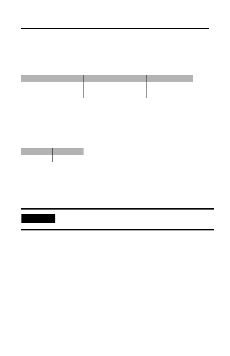
The following table describes the related user manual that is available for this module. To
order a copy or to view or download an online version, visit The Automation Bookstore at:
www.theautomationbookstore.com
For information about: See this document: Publication number:
Programming, calibrating and
troubleshooting the barrel
temperature module
Barrel Temperature Control Module
User Manual
1746-UM010
Determine the Module’s Chassis Power Requirement
When computing power supply requirements, add the values shown below to the
requirements of all other modules in the SLC
power supply:
5V dc amps 24V dc amps
0.110 0.085
® chassis to prevent overloading the chassis
Choose a Module Slot in a Local I/O Chassis
Place your module in any slot of an SLC 500TM module, or modular expansion chassis, except
for the left–most slot (slot 0), reserved for the SLC processor or adapter modules.
Installation Considerations
Most thermocouple–type applications require an industrial enclosure to reduce the effects of
electrical interference. Thermocouple inputs are highly susceptible to electrical noises due to
the small signal amplitudes (microvolt/C°). Isolate them from other input wiring and
modules that radiate electrical interference.
Group your modules within the I/O chassis to minimize adverse effects from radiated
electrical noise and heat. Consider the following conditions when selecting a slot location.
Position the module away from modules that:
Publication 1746-IN020B-EN-P - July 2002
For proper operation, use this module with a local processor. The
module is not designed to operate in a remote chassis.
• connect to sources of electrical noise such as relays and ac motor drives
• generate significant heat, such as 32–point I/O modules
Page 5

Barrel Temperature Control Module 5
WARNING
!
Install the Module
To install your module into the chassis:
1. Turn off the chassis power supply.
If you insert or remove the module while backplane power is on, an
electrical arc can occur. This could cause an explosion in hazardous
location installations. Be sure that power is removed or the area is
nonhazardous before proceeding.
2. Align the circuit board of the thermocouple module with the card guides located at
the top and bottom of the chassis.
3. Slide the module into the chassis until both top and bottom retaining clips are
secured. Apply firm even pressure on the module to attach it to its backplane
connector. Never force the module into the slot.
4. Cover unused slots with the card slot filler, catalog number 1746–N2.
Publication 1746-IN020B-EN-P - July 2002
Page 6

6 Barrel Temperature Control Module
card guides
top and bottom
releases
retaining clips
5. To remove, press the releases at the top and bottom of the module, and slide the
module out of the chassis slot.
Publication 1746-IN020B-EN-P - July 2002
Page 7

Barrel Temperature Control Module 7
WARNING
!
CJC sensors
retaining screws
RTB
SLOT
RACK
MODULE
Remove/Install the Removable Terminal Block
The module ships with an attached an 18-position removable terminal block (RTB). When
you install the module, it is not necessary to remove the RTB. If you ever need to remove it,
follow this procedure:
1. Alternately loosen the two retaining screws to avoid cracking the RTB.
2. Grasp the RTB at the top and bottom and pull outward and down. When removing
the RTB, be careful not to damage the CJC sensors.
To install the RTB:
3. Use the write–on label to identify the slot, chassis and module type.
1. Remove power from the SLC 500 chassis.
When you connect or disconnect the Removable Terminal Block
(RTB) with field side power applied, an electrical arc can occur. This
could cause an explosion in hazardous location installations. Be sure
that power is removed or the area is nonhazardous before proceeding.
Publication 1746-IN020B-EN-P - July 2002
Page 8

8 Barrel Temperature Control Module
ATTENTION
!
SLOT
RACK
MODULE
CJC sensors
retaining screws
RTB
2. Make certain the color of the RTB mathces the color band on the module.
Inserting a wired RTB on an incorrect module can damage the module’s
circuitry when power is restored.
3. View the write–on label to identify the slot, chassis and module type.
4. Align the RTB retaining screws with the mating connector on the module. Be careful
not to damage the CJC sensors.
5. Press the RTB firmly onto the connector contacts.
6. Alternately tighten the two retaining screws to avoid cracking the RTB. Tighten to a
maximum 6-8 inch-pounds.
Publication 1746-IN020B-EN-P - July 2002
Page 9

Wire the RTB
ATTENTION
!
CJC A+
CJC A-
Do NOT use these
connections
CJC B+
CJC Assembly
CJC Assembly
CJC B-
Retaining Screw
Retaining Screw
Channel 0+
Channel 0Channel 1+
Channel 1-
Channel 2+
Channel 2-
Channel 3+
Channel 3-
n/c
spare part catalog number:
1746-RT32
Always attach red
lug to the CJC+
terminal
CJC Senosr part number
A40845-221-01
Use the following illustration to wire the RTB:
Cold Junction Compensation (CJC)
Barrel Temperature Control Module 9
Do not remove or loosen the cold junction compensating thermistors
located on the terminal block. Both thermistors are critical to
ensure accurate thermocouple input readings at each
channel. The module will not operate in the thermocouple mode if a
thermistor is removed
In case of accidental removal of one or both thermistors (part number A40845-221-01),
replace them by connecting them across the CJC terminals located at the top and/or bottom
left side of the terminal block. Always connect the red lug to the (+) terminal (to CJC A+ or
CJC B+) as shown below.
Publication 1746-IN020B-EN-P - July 2002
Page 10

10 Barrel Temperature Control Module
Wiring Guidelines
Follow these guidelines when planning your system wiring.
• To limit the pickup of electrical noise, keep thermocouple and millivolt signal wires
away from power and load lines.
• For high immunity to electrical noise, use Alpha 5121 (shielded, twisted pair) or
equivalent wire for millivolt sensors; or use shielded, twisted pair thermocouple
extension lead wire specified by the thermocouple manufacturer. Using the incorrect
type of thermocouple extension wire or not following the correct polarity may cause
invalid readings. See IEEE Std. 518, Section 6.4.2.7 or contact your sensor
manufacturer for additional details.
• When trimming cable leads, minimize the length of unshielded wires.
• Ground the shield drain wire at only one end of the cable. The preferred location is at
the I/O chassis ground.
• For maximum noise reduction, use 3/8 inch braid wire to connect cable shields to the
nearest I/O chassis mounting bolt. Then connect the I/O chassis to earth ground.
These connections are a requirement regardless of cable type.
• Tighten terminal screws to 6-8 inch-pounds. Excessive tightening can strip the screw.
• The open–circuit detector generates approximately 20 nano–amperes into the
thermocouple cable. A total lead resistance of 25 ohms (12.5 one–way) will produce
0.5 mV of error.
• Follow system grounding and wiring guidelines found in your SLC 500 Modular
Hardware Style User Manual, publication 1747–UM011.
Publication 1746-IN020B-EN-P - July 2002
Page 11

Barrel Temperature Control Module 11
Signal Wires
Extract the drain wire but
remove the foil shield, at
the module-end of the
cable.
Drain Wire
Signal Wires
Remove the foil shield
and drain wire from
sensor-end of the cable
Preparing and Wiring the Cables
To prepare and connect cable leads and drain wires, follow these steps:
1. At each end of the cable, strip some casing to expose individual wires.
2. Trim signal wires to 5–inch lengths beyond the cable casing. Strip about 3/16 inch
(4.76 mm) of insulation to expose the ends of the wires.
3. At the module–end of the cables:
- extract the drain wire and signal wires
- remove the foil shield
- bundle the input cables with a cable strap
4. Connect drain wires together and solder them to a 3/8” wire braid, 12” long. Keep
drain wires as short as possible.
5. Connect the 3/8” wire braid to the nearest chassis mounting bolt.
6. Connect the signal wires of each channel to the terminal block.
Publication 1746-IN020B-EN-P - July 2002
Page 12

12 Barrel Temperature Control Module
IMPORTANT
Wires
3/8
Make unshielded wires as
short as possible.
Limit braid length to 12” or
less. Solder braid to lug on
bottom row of I/O chassis
Connect I/O chassis
bolt to earth ground
Solder drain wires to
braid at casing.
Make unshielded wires as short as possible.
3/8
Signal
Wires
Terminal Block
Chnl 0
Chnl 1
Chnl 2
Chnl 3
n/c
Cables
7. At the source-end of cables from mV devices (see following figure):
• remove the drain wire and foil shield
• apply shrink wrap as an option
• connect to mV devices keeping the leads short
Publication 1746-IN020B-EN-P - July 2002
If noise persists, try grounding the opposite end of the cable. Ground
one end only.
Page 13

Barrel Temperature Control Module 13
WARNING
!
AVERTISSEMENT
!
The following information applies when
operating this equipment in hazardous
locations:
Products marked “CL I, DIV 2, GP A, B, C, D” are
suitable for use in Class I Division 2 Groups A, B, C,
D, Hazardous Locations and nonhazardous locations
only. Each product is supplied with markings on the
rating nameplate indicating the hazardous location
temperature code. When combining products within
a system, the most adverse temperature code (lowest
“T” number) may be used to help determine the
overall temperature code of the system.
Combinations of equipment in your system are
subject to investigation by the local Authority Having
Jurisdiction at the time of installation.
EXPLOSION HAZARD
• Do not disconnect
equipment unless
power has been
removed or the area is
known to be
nonhazardous.
• Do not disconnect
connections to this
equipment unless
power has been
removed or the area is
known to be
nonhazardous. Secure
any external
connections that mate
to this equipment by
using screws, sliding
latches, threaded
connectors, or other
means provided with
this product.
• Substitution of
components may impair
suitability for Class I,
Division 2.
• If this product contains
batteries, they must
only be changed in an
area known to be
nonhazardous.
Informations sur l’utilisation de cet équipement
en environnements dangereux :
Les produits marqués "CL I, DIV 2, GP A, B, C, D" ne
conviennent qu’à une utilisation en environnements
de Classe I Division 2 Groupes A, B, C, D dangereux
et non dangereux. Chaque produit est livré avec des
marquages sur sa plaque d’identification qui
indiquent le code de température pour les
environnements dangereux. Lorsque plusieurs
produits sont combinés dans un système, le code de
température le plus défavorable (code de
température le plus faible) peut être utilisé pour
déterminer le code de température global du
système. Les combinaisons d’équipements dans le
système sont sujettes à inspection par les autorités
locales qualifiées au moment de l’installation.
RISQUE D’EXPLOSION
• Couper le courant ou
s’assurer que
l’environnement est
classé non dangereux
avant de débrancher
l'équipement.
• Couper le courant ou
s'assurer que
l’environnement est
classé non dangereux
avant de débrancher les
connecteurs. Fixer tous
les connecteurs
externes reliés à cet
équipement à l'aide de
vis, loquets coulissants,
connecteurs filetés ou
autres moyens fournis
avec ce produit.
• La substitution de
composants peut rendre
cet équipement
inadapté à une
utilisation en
environnement de
Classe I, Division 2.
• S’assurer que
l’environnement est
classé non dangereux
avant de changer les
piles.
Publication 1746-IN020B-EN-P - July 2002
Page 14

14 Barrel Temperature Control Module
Specifications
Module Location SLC chassis - any I/O module slot except 0
Input from System Backplane 5Vdc @ 0.110 A, 24Vdc @ 0.085A
Thermocouple Types b, c, d, e, j, k, n, r, s, t
Input Voltage -50 to +50mV and -100 to +100mV
Number of Channels 4 (backplane and channel-to-channel isolated)
A/D Conversion Method Sigma-Delta modulation
Input Filtering Analog filter with low-pass digital filter
Normal mode rejection
between
[+] input and [-] input
Common mode rejection
between inputs and chassis
ground
Channel bandwidth (-3db) 8Hz
Calibration Once every six months
Isolation Tested to 1000Vac for 60 sec. between channels and between user connections
Operating Temperature
Storage Temperature IEC 60068-2-1 (Test Ab, Un-packaged Non-operating Cold),
Relative Humidity IEC 60068-2-30 (Test Db, Un-packaged Non-operating Damp Heat):
Required Terminal Block Cat. No. 1746-RT32
Wiring
Wire Category
Tor qu e
Enclosure Type Rating None (open style)
Certifications
(when product is marked)
User Manual Publication 1746-UM010, Barrel Temperature Module User Manual
1
Use this conductor category information for planning conductor routing as described in publication 1770-4.1, Industrial
Automation Wiring and Grounding Guidelines.
2
See the Product Certification link at www.ab.com for Declarations of Conformity, Certificates, and other certification
details.
1
2
Greater than 50dB @ 50Hz
Greater than 60dB @ 60Hz
Greater than 120dB @ 50/60 Hz with 1K ohm imbalance
and backplane connections
IEC 60068-2-1 (Test Ad, Operating Cold),
IEC 60068-2-2 (Test Bd, Operating Dry Heat),
IEC 60068-2-14 (Test Nb, Operating Thermal Shock):
0-60oC (32–140oF)
IEC 60068-2-2 (Test Bc, Un-packaged Non-operating Dry Heat),
IEC 60068-2-14 (Test Na, Un-packaged Non-operating Thermal Shock):
–40 to 85oC (–40 to 185oF)
5–95% non condensing
24-14 AWG
2
6-8 in-lbs.
UL UL Listed Industrial Control Equipment
CSA CSA Certified Process Control Equipment
CSA CSA Certified Process Control Equipment for Class I, Division 2 Group
CE European Union 89/336/EEC EMC Directive, compliant with:
C-Tick Australian Radiocommunications Act, compliant with:
A,B,C,D Hazardous Locations
EN 50082-2; Industrial Immunity
EN 61326; Meas./Control/Lab., Industrial Requirements
EN 61000-6-2; Industrial Immunity
EN 61000-6-4; Industrial Emissions
AS/NZS 2064; Industrial Emissions
Publication 1746-IN020B-EN-P - July 2002
Page 15

Notes:
Barrel Temperature Control Module 15
Publication 1746-IN020B-EN-P - July 2002
Page 16

Rockwell Automation Support
Rockwell Automation provides technical information on the Web to assist you in using its products.
At http://support.rockwellautomation.com
, you can find technical manuals, a knowledge base of
FAQs, technical and application notes, sample code and links to software service packs, and a
MySupport feature that you can customize to make the best use of these tools.
For an additional level of technical phone support for installation, configuration, and troubleshooting,
we offer TechConnect support programs. For more information, contact your local distributor or
Rockwell Automation representative, or visit http://support.rockwellautomation.com
.
Installation Assistance
If you experience a problem within the first 24 hours of installation, please review the information
that's contained in this manual. You can also contact a special Customer Support number for initial
help in getting your product up and running.
United States 1.440.646.3434
Outside United States Please contact your local Rockwell Automation representative for any
Monday – Friday, 8 a.m. – 5 p.m. EST
technical support issues.
New Product Satisfaction Return
Rockwell Automation tests all of its products to ensure that they are fully operational when shipped
from the manufacturing facility. However, if your product is not functioning and needs to be
returned, follow these procedures.
United States Contact your distributor. You must provide a Customer Support case number
Outside United States Please contact your local Rockwell Automation representative for the return
Allen-Bradley, Rockwell Automation, SLC, SLC 500, and TechConnect are trademarks of Rockwell Automation, Inc.
Trademarks not belonging to Rockwell Automation are property of their respective companies.
(see phone number above to obtain one) to your distributor in order to
complete the return process.
procedure.
Publication 1746-IN020B-EN-P - July 2002 PN 957689-86
Supersedes Publication 1746-5.20 - February 1999 Copyright © 2002 Rockwell Automation, Inc. All rights reserved. Printed in the U.S.A.
 Loading...