

Page 1

Blow-molding Module
ATTENTION
!
WARNING
!
(catalog number 1746-BLM )
Before you begin
Installation Instructions
Use this document as a guide to installing and powering-up your Blow-molding
Module. W e assume tha t you are already familiar with the SLC 500
Logic Controllers and associated I/O modules.
™
family of Small
Tools that you need
• 1/8” slotted screwdriver
Handling the Module
Take these precautions to guard against ESD damage:
Electrostatic discharge can damage the module. Follow these
guidelines:
• touch a grounded object to discharge potential static
• wear an approved grounding wriststrap
• do not touch circuit components inside the module
• if available, use a static-safe work station
• when not in use, store the module in its anti-static bag.
Do not insert or remove this module while backplane power is
on. An electrical arc may occur that can cause an explosion in
a hazardous environment and/or cause damage to the module
or degrade its performance.
Publication 1746-IN014B- EN-P - January 2001
Page 2

2 Blow-molding Module
ATTENTION
!
IMPORTANT
Important User Information
Because of the variety of uses for the products described in this publication, those
responsible for the application and use of this control equipment must satisfy
themselves that all necessary steps have been taken to assure that each application
and use meets all performance and safety requirements, including any applicable
laws, regulations, codes and standards.
The illustrations, charts, sample programs and layout examples shown in this guide
are intended solely for purposes of example. Since there are many variables and
requirements associated with any particular installation, Allen-Bradley does not
assume responsibility or liability (to include intellectual property liability) for actual
use based upon the examples shown in this publication.
Allen-Bradley publication SGI-1.1, Safety Guidelines for the Application, Installation
and Maintenance of Solid-State Control (available from your local Allen-Bradley
office), describes some important differences between solid-state equipment and
electromechanical devices that should be taken into consideration when applying
products such as those described in this publication.
Reproduction of the contents of this copyrighted publication, in whole or part,
without written permission of Rockwell Automation, is prohibited.
Throughout this manual we use notes to make you aware of safety considerations:
Attention statements help you to:
• identify a hazard
• avoid a hazard
• recognize the consequences
Publication 1746-IN014B-EN-P - January 2001
Identifies information about practices or circumstances that can
lead to personal injury or death, property damage or economic
loss
Identifies information that is critical for successful application
and understanding of the product.
Page 3

Blow-molding Module 3
Recommendation for using associated software
To program the SLC processor to interface the module with molding machine
operation, your PC should be equipped with programming software RSLogix 500™
from Rockwell Software. For instructions on using the software, refer to the
documentation that accompanied it.
What you need to do to set up and operate the module?
This document covers a description of the module and its operation, wiring and
configuring the module, writing ladder logic and using associated data files,
calibrating, tuning, troubleshooting, and specifications.
Step Description Page
1 Module description 4
2 Machine applications of the module 9
3 Module operation with an accumulator machine 14
4 Module operation with a continuous extrusion machine 16
5 Determining an axis setpoint 18
6 Wiring the module 19
7 Configuring the SLC processor (including I/O, M0/M1, and G file) 25
8 Axis Control Structures in M0/M1 Files 30
9 Using output and input image tables 31
10 Writing Ladder Logic 35
11 Calibrating the module 37
12 Tuning a PID Loop 38
13 Troubleshooting 39
Specifications 41
Descriptions of module parameters 43
European Communities (EC) Directive Compliance 44
Rockwell Automation Support 45
Hazardous Location Approval 46
Publication 1746-IN014B- EN-P - January 2001
Page 4

4 Blow-molding Module
Step: 1 Module description
We cover these aspects of module description:
• features
• overview
• communication with SLC processor
• internal microprocessor
• internal PID control algorithm
• analog I/O
• digital I/O
Features
This 4-axis position-control module has these features:
• Open-loop or closed-loop control
• Independent and coordinated axis control
• Position- and time-based control
• Accumulator push-out control
• Zero-scale/full-scale (offset & span) calibration for position inputs
• PID with anti-windup, bumpless parameter changes, setpoint weighting, and
limited high-frequency derivative gain.
• Profile interpolation (linear or cubic spline) between setpoints
• Converging/diverging tooling (direct/reverse acting control)
• Three hold values per axis: manual position, purge, or die gap
• Independent profile scale and offset adjustments
• Automatic parison weight adjustment
• Setpoint marking
Publication 1746-IN014B-EN-P - January 2001
Page 5
Blow-molding Module 5
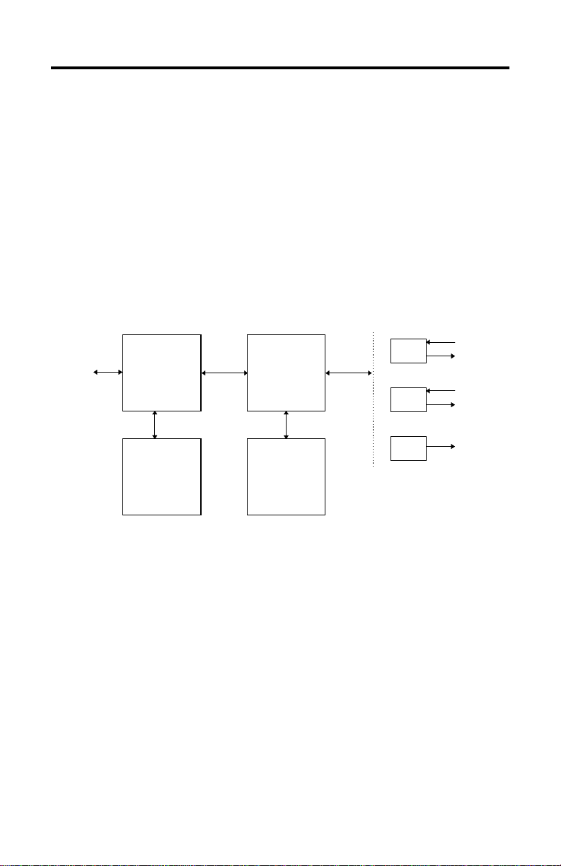
Overview
The module performs its servo control task independently, but is dependent on the
SLC processor for all of its configuration and run-time information. The processor
may be also be used to supply process data or timing information over the
backplane in certain situations (e.g. parison drop synchronization on continuous
extrusion machines, or accumulator position in reciprocating screw machines).
The module uses a digital signal processor running a
Proportional-Integral-Derivative (PID) algorithm to control four axes of motion.
Four analog inputs and four analog outputs are used for process variables and
signals, while four digital inputs and four digital outputs are used for start-of-drop
synchronization and profile step synchronization si gnals, respectively. An e xcitation
voltage is provided for use with linear potentiometers.
Digital
PLC Interface
Shared Memory
Module µP
Local Memory
I/O
Analog
I/O
Excitation
Publication 1746-IN014B- EN-P - January 2001
Page 6

6 Blow-molding Module
Communication with the SLC Processor
• shared memory
• control bit/status bit handshake
• micro processor
• PID control algorithm
• digital I/O
• analog I/O
Shared memory
From the ladder programmer’s perspective, communication with the module is via
five data files located in shared memory on the module:
Config(G) File contains information regarding the operational mode and feature
settings of the module. You specify the contents of this file with
the ladder logic programming utility (RSLogix500). Entries in the
file are static and read-only from the module’s perspective (e.g.
time vs. position based operation). This file is automatically
downloaded to the module when you switch the SLC processor
to Run mode.
Output File contains 32 16-bit entries used by ladder program to command
module operation. The Output File may also be used to supply
process data to the module in certain situations. Entries in this
file are updated automatically, at the end of each scan, by the
SLC processor from the user data file but may be written at any
time by immediate I/O instructions in the ladder program.
Input File contains 32 16-bit entries used by ladder program to extract
status information from the module. The Input File contains
acknowledge bits corresponding to control bits in the Output
File, as well as information pertaining to the profile executing on
each analog I/O channel (step number, setpoint, analog input,
process variable, control output, etc.) and a parameter error flag.
The entries in this file are read automatically, once per scan, by
the SLC processor into the user data file, but may be read at any
time by immediate I/O instructions in ladder program.
Publication 1746-IN014B-EN-P - January 2001
Page 7

Blow-molding Module 7
M0 File contains four axis control structures and five setpoint profiles.
Each axis has a variety of PID and profiling options, controlled
by its axis control structure. Each axis also has a unique
256-point setpoint profile. A single master setpoint profile is used
with an “interpolate” command to ease the task of generating
setpoint profiles.
Entries in the M0 File are written by move or copy instructions in
ladder program. Unlike changes made to the Output File, which
are automatically detected by the module, the module must be
explicitly instructed to download axis-control structures and
setpoint profiles from shared memory (done by setting bits in the
Output File).
M1 File contains four axis-status structures, four process-variable profiles,
and a single interpolated profile. Axis-status structures are copies
of respective axis-control structures, except that status
information has been inserted by the module. Each
process-variable profile provides a record of the actual position
response to a setpoint profile. The interpolated profile is the
result of either a linear or natural cubic-spline interpolation
performed between the setpoints specified in the master setpoint
profile.
Unlike the Input File, which is automatically updated, the
module must be explicitly instructed to upload axis-status
structures, process variable profiles, and the interpolated profile
to shared memory (done by setting bits in the Output File).
Entries in this file are then read by move or copy instructions in
ladder program.
Handshake with control and status bits
To ease the task of synchronizin g module op erations with y our ladder program, all
control bits in the Output File have a corresponding status bit in the Input File.
Upon detecting a change in a control bit from zero to one, the module performs
any associated processing and then acknowledges completion by setting the
corresponding status bit to one. The status bit w ill r emain se t as long as the control
bit remains set. When the control bit is cleared, the status bit will be cleared
immediately in acknowledgment.
Exceptions to this protocol are the profile enable control/status bits and the
control/status bits for the digital inputs and digital outputs. See step 9 for complete
descriptions of these and other bits.
Publication 1746-IN014B- EN-P - January 2001
Page 8

8 Blow-molding Module
Module’s microprocessor
The module processor is a 16-bit fixed-point digital signal processor (DSP). It
communicates with the analog I/O channels over a high speed (2MHz) full-duplex
synchronous serial link. Serial connection between the processor and analog I/O
hardware facilitates electrical isolation. Digital I/O is performed in a similar fashion.
The module processor manages all communications between the module and the
SLC processor. It performs such functions as interpolation between profile
setpoints, loop tuning, and calculation of calibration coefficients in addition to
executing the control algorithm.
Module’s PID control algorithm
For servo control, the module uses a Proportional + Integral + Derivative a lgorithm
with anti-windup, high-frequency derivative gain limiting and setpoint weighting.
Anti-windup is achieved by modeling the actuator (normally a valve amplifier) as a
nonlinear device that operates linearly over a limited range, beyond which it
saturates.
An additional error signal is formed by taking the difference of raw controller
output, v(n), and control output, u(n), which is clamped at the actuator saturation
limits. This signal is multiplied by gain 1/Tt, where Tt is called the integrator
tracking time and summed into the integral term. High-frequency derivative gain
limiting lets you compensate for derivative term susceptibility to high frequency
noise. Setpoint weighting provides a mechanism for independent tuning of setpoint
and load response.
Digital I/O
There are four fully isolated digital inputs on the module. They are of the
current-sinking type. Their primary use is for start-of-parison-drop synchronization
on continuous extrusion machines. The digital inputs may be used as general
purpose inputs if the start of drop synchronization feature is not needed.
There are four isolated digital outputs on the module. They are of the
open-collector (current-sinking) type and share a common 24VDC (nominal)
external power supply. Their primary use is as profile step-synchronization
indicators. The digital outputs may be used as general purpose outputs if the step
synchronization feature is not needed. See page 41 for complete specifications.
Analog I/O
There are four analog I/O channels on the module. Each channel consists of a
14-bit analog-to-digital converter and a 14-bit digital to analog converter. As a
group, the four I/O channels and excitation output are optically isolated from the
remainder of the module. The high common mode input range of the input
amplifiers and the isolated nature of LVDTs and linear potentiometers make it
unnecessary to isolate the channels from one another. See page 41 for complete
specifications.
Publication 1746-IN014B-EN-P - January 2001
Page 9

Blow-molding Module 9
Step: 2 Machine applications of the module
Each module can control up to four axes of closed-loop position control on most
types of blow-molding machines. Configurations include:
• accumulator push-out control and three parison axes
• two accumulator push-outs and two parison axes
You can use multiple modules on machines with more than four heads.
Publication 1746-IN014B- EN-P - January 2001
Page 10
10 Blow-molding Module
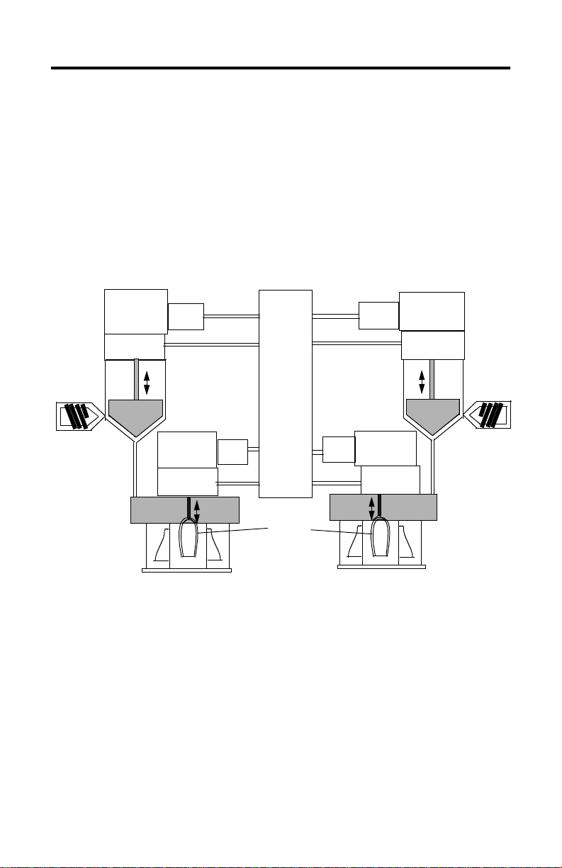
Control of Accumulator Head Machines
The module controls parison wall thickness on accumulator machines by following
a setpoint profile of wall thickness vs. accumulator ram position. In this
configuration, the module is capable of controlling up to three blow molding
heads. One analog I/O channel is used for accumulator ram velocity control while
the others are used for mandrel position control.
Optionally the module may simply monitor ram position. Mandrel position and
accumulator ram velocity are normally both specified as a function of accumulator
ram position. Since the module supports a mixture of time- and position-based
modes, you may also specify accumulator position as a function of time.
Proportional
Valve and
Cylinder
Position
Transducer
ram
mandrel
Valve
Amp
accumulator
Proportional
Valve and
Cylinder
Position
Transducer
Valve
Amp
Analog
Outputs
Analog
Inputs
1746-BLM
Module
Analog
Outputs
Analog
Inputs
parison
Valve
Amp
Valve
Amp
accumulator
Proportional
Valve and
Cylinder
Position
Transducer
mandrel
Proportional
Valve and
Cylinder
Position
Transducer
ram
Publication 1746-IN014B-EN-P - January 2001
Page 11
Blow-molding Module 11
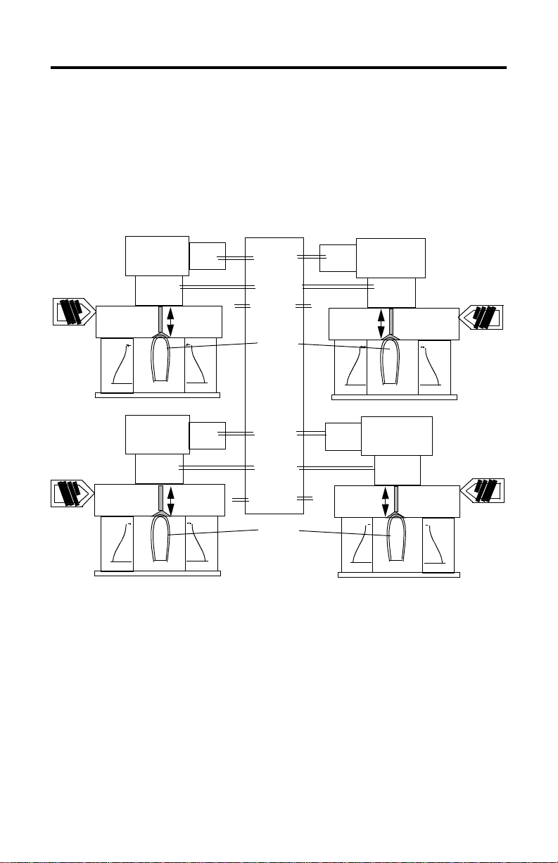
Control of Continuous Extrusion Machines
The module controls parison wall thickness on continuous extrusion machines by
following a setpoint profile of wall thickness vs. time. The module is capable of
controlling up to four blow molding heads in this mode. Each of the m odule’s four
analog I/O channels is used for mandrel position control. Mandrel position is a
function of the elapsed time since the last synchronization signal, indicating start of
parison drop.
Servo Valve and
Hydraulic
Cylinder
mandrel
Servo Valve and
Hydraulic
Cylinder
mandrel
LVDT
LVDT
Valve
Amp
Valv e
Amp
Analog
Outputs
Analog
Inputs
Digital
Sync Pulses
parison
1746-BLM
Module
Analog
Outputs
Analog
Inputs
Digital
Sync Pulses
parison
Valve
Amp
Valve
Amp
Servo Valve and
Hydraulic
Cylinder
LVDT
mandrel
Servo Valve and
Hydraulic
Cylinder
LVDT
mandrel
Publication 1746-IN014B- EN-P - January 2001
Page 12

12 Blow-molding Module
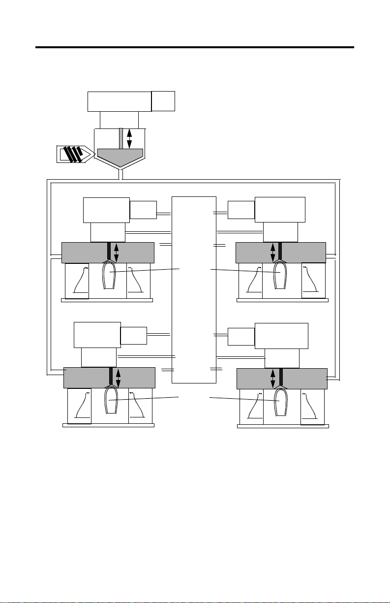
Control of Reciprocating Screw Machines
Reciprocating screw machines have multiple heads and a single accumulator.
Control of accumulator position is performed by the SLC processor. The module
may be used to monitor the accumulator (screw) position in either of two ways on
this type of machine:
• with an analog input to the module: Each module configured in this
manner can control three heads. This method offers optimal performance.
However, hardware utilization may not be as high as the following method
depending on the number of extrusion heads.
• with a separate high speed analog module: The SLC processor must
read position information from an analog module and update the 1746-BLM.
A selectable timed interrupt (STI) instruction can be used with a 4ms period
and variability << 1ms (tested on a SLC5/04 CPU with no other interrupt
sources). This is adequate for 256- setpoint profiles with drop times > 1
second (~4ms/setpoint). Drop times of less than one second necessitate
monitoring accumulator position with the 1746-BLM. Avoid using other STI
instructions with higher priority.
Publication 1746-IN014B-EN-P - January 2001
Page 13
Blow-molding Module 13
Proportional Valve and
Cylinder
Position
Transd ucer
ram
Servo Valve and
Hydraulic
Cylinder
LVDT
mandrel mandrel
Servo Valve and
Hydraulic
Cylinder
LVDT
mandrel
Valv e
Amp
Valve
Amp
Single accumulator controlled by
separate analog module and SLC
ladder logic.
Valv e
Amp
Analog
Outputs
Analog
Inputs
Digital
Sync Pulses
parison
1746-BLM
Module
Analog
Outputs
Analog
Inputs
Digital
Sync Pulses
Valv e
Amp
Valv e
Amp
Servo Valve and
Hydraulic
Cylinder
LVDT
Servo Valve and
Hydraulic
Cylinder
LVDT
mandrel
parison
Publication 1746-IN014B- EN-P - January 2001
Page 14

14 Blow-molding Module
IMPORTANT
Step: 3 Module operation wi th an ac cumulator machine
Position-based Operation
In position-based mode, setpoint profiles are specified as a function of the position
of a second, independent axis position. Here the independent axis corresponds to
the accumulator ram position, while the dependent axis corresponds to mandrel
position (or ram velocity).
Conceptually, the shot size of the independent axis is divided into 256 segments.
When the accumulator ram position falls within the range of a particular segment,
the number of that segment is used as an index into the setpoint profile to
determine the current setpoint for the mandrel position (or ram velocity).
Although you may specify profile sizes less than 256 in the
config file, the module expands these to 256-point profiles
after downloading from shared memory. Internally to the
module, all profiles are 256 points in l ength. Similarly, process
variable profiles are compressed from the module’s 256-point
internal representation to your desired profile size prior to
uploading.
Controlling Mandrel Position
Static control: Mandrel position may be controlled statically by means of the three
axis-hold values and corresponding hold-value control bits accessible via the
module output file. The hold values are prioritized with hold value #0 being highest
priority and hold value #2 being lowest.
In absence of an active profile, the highest priority enabled hold value becomes the
position setpoint. By convention, the fully-closed mandrel p osition is the zero-sc ale
calibration point, while the fully-open mandrel position is the full-scale calibration
point.
Dynamic control: Mandrel position may be controlled dynamically by
downloading a setpoint profile to the module’s M0 file and setting the profile
enable bit. Then, upon detecting the independent axis position at shot size, the
module will automatically update the mandrel position once per millisecond
through the last profile setpoint.
The last setpoint is maintained until all of the following are complete:
• profile enable bit is cleared
• independent axis is again at shot size
• profile enable bit is set again, which starts the next profile
Publication 1746-IN014B-EN-P - January 2001
Page 15

Blow-molding Module 15
Monitoring Mandrel Position
Instantaneous mandrel position may be monitored by reading the current process
variable from the module’s input file. Several other values of interest are also
available for each axis (e.g. control output, profile step, etc.). Process variable
profiles may be read from the module’s M1 file.
Controlling R a m Velo c ity
Accumulator ram velocity is controlled in position-based mode by specifying ram
velocity as a function of ram position. As with mandrels, rams are calibrated for
zero-scale and full-scale positions. Velocity is then expressed as velocity = change
of position/millisecond. By convention, the fully-forward ram position is the
zero-scale calibration point, while the fully-retracted ram position is the full-scale
calibration point. This implies that negative velocities result in moving the ram
forward.
Velocity can be controlled in either open loop or closed loop. You select
closed-loop velocity control by setting the appropriate axis’ velocity-control bit in
the module output file. Since hydraulic valves generally provide a constant
hydraulic flow with a constant command input, setpoints in open-loop mode
inherently specify velocity. Once closed-loop velocity control is enabled, hold v alue
#2 is interpreted as shotsize, and the axis’ step synchronization output is enabled as
an at-shotsize indicator.
Operation by Controlling Ram Velocity
Normally, ram velocity is controlled in closed loop using a single module analog
I/O pair. A velocity profile (as opposed to a position profile) is necessary since the
independent axis is the ram position. The remaining three analog I/O pairs are
available for controlling machine heads.
Operation by Monitoring Ram Velocity
This mode of operation is identical to operation with ram velocity control, except
ram position is monitored only (a velocity profile for the ram is not used). You can
control up to three machine heads per 1746-BLM. The resulting unused analog
output is available for general (open-loop) use.
Publication 1746-IN014B- EN-P - January 2001
Page 16

16 Blow-molding Module
TIP
Operation with an Auxiliary Position Input
This mode of operation lets you control four machine heads per 1746-BLM. Your
ladder program is responsible for calibration and scaling of process variable data
sent to the module via the output file. A value of -32768 corresponds to the
fully-forward ram position and +32767 corresponds to the at-shotsize ram position.
See page 12 for additional information on controlling with a separate, high-speed
analog module.
Step: 4 Module operation wi th a con tinu ous extrusion machine
Time-based Oper ation
In time-based mode, setpoint profiles are specified as a function of the elapsed time
starting with the leading edge of the start-of-drop synchronization signal. Profile
duration may be held constant or derived from the time between previous sync
pulses. In either case, profile duration is divided into 256 segments.
When the elapsed time since the start of drop falls within the range of a particular
segment, the number of that segment is used as an index into the setpoint profile to
determine the current setpoint for the mandrel posi tion. Should a ne w start-of-drop
synchronization pulse occur prior to completion of a profile in progress, a new
profile will be started. If the profile duration expires without receiving a
synchronization pulse, the last profile setpoint will be maintained indefinitely.
Although you may specify profile sizes less than 256 in the
config file, the module expands these to 256-point profiles
after a download. Internally to the module, all profiles are 256
points in length. Similarly, process variable profiles are
compressed from the module’s 256-point internal
representation to your desired profile size prior to an upload.
Publication 1746-IN014B-EN-P - January 2001
Page 17

Blow-molding Module 17
Controlling Mandrel Position
Static Control: Mandrel position may be controlled statically with three axis-hold
values and corresponding hold-value control bits accessible via the module output
file. Hold values are prioritized with hold value #0 being highest, and hold value #2
being lowest. In time-based mode the hold values have no special interpretation.
In absence of an active profile, the highest priority enabled hold value becomes the
position setpoint.
Dynamic control: Mandrel position may be controlled dynamically by
downloading a setpoint profile to the module’s M0 file and setting the profile
enable bit. Then, upon receipt of an axis sync input signal, the module will
automatically update the mandrel position setpoint every millisecond until the
profile duration has expired or a new synchronization pulse is received.
Monitoring Mandrel Position
Instantaneous mandrel position may be monitored by reading the current process
variable from the module’s input file. Several other values are also available for
each axis (e.g. control output, profile step, etc.). Process variable profiles may be
read from the module’s M1 file.
Generating a Synchronization Signal
The module examines its digital inputs once every millisecond, so the minimum
pulse width (high or low) for external synchronization inputs is also one
millisecond. The module may also be configured via the G file to accept
synchronization inputs via its input file.
Modes of time-based operation
Fixed profile timing: For fixed profile times, the profile-time filter constant should
be set to zero. This way, the default profile time is used as the profile duration for
every profile, regardless of sync input pulse period.
Variable profile timing: The module may also be programmed to adapt to the
machine cycle time by setting the profile-time filter constant to values other than
zero. The programmed value enables a digital lowpass filter on the profile time
sequence. This has an effect similar to averaging previous profile times. Larger filter
time constants result in more filtering.
Publication 1746-IN014B- EN-P - January 2001
Page 18

18 Blow-molding Module
Step: 5 Determining an axis setpoint
All position setpoints and process variables are represented in the SLC500 16-bit
signed integer format, where the minimum value of -32768 corresponds to
zero-scale (fully-closed or fully-forward) and the maximum value of +32767
corresponds to full-scale (fully-open or fully-retracted).
The setpoint for a machine axis comes from one of four prioritized sources: an
active profile or one of three hold values. When enabled, the profile setpoint is
highest priority. In absence of an active profile, hold values 0, 1 and 2 are applied
in order of decreasing priority, with value 0 having the highest priority.
The tooling position for hold values is a function of the user setpoint and
calibration data. Profile setpoints may be affected by three other factors:
• offset adjustment from the axis control structure
• scale factor from the axis control structure
• offset resulting from a comparison of the current profiles mean value with
that of a previous profile
The offset and scale adjustments are provided to let you manipulate the weight of a
profile without individually changing each setpoint in the original profile and
re-downloading. The mean value comparison is done as part of an “automatic
weight control” feature.
When the weight control bit in the output file is set, the current profile mean value
is calculated. Subsequent profiles are then offset to achieve this same mean value.
This maintains a constant part weight. Note that all such modifications to profile
setpoints are performed immediately after a profile is downloaded. To modify a
profile iteratively, you must repeatedly set the control bit that downloads the
setpoint profile.
Publication 1746-IN014B-EN-P - January 2001
Page 19

Blow-molding Module 19
WARNING
!
ATTENTION
!
Step: 6 Wiring the module
When you insert or remove the module while the backplane
power is on, or you connect or disconnect the RTB with field
side power applied, an electrical arc can occur. This could
cause an explosion in hazardous location installations.
Be sure that power is removed or the area is nonhazardous
before proceeding. Repeated electrical arcing causes wear to
contacts on both the module and its mating connector. Worn
contacts may create electrical resistance that can affect module
operation.
Disconnect all power to the SLC system before wiring.
We recommend making connections to the module with:
• Interface Module (cat. no. 1492-IFM40F)
• Interface Cable (cat. no. 1492-CABLE010H)
The Interface Module is a 40-pin miniature terminal block. The Interface Cable is
one meter long.
For additional information on these items, Refer to Wiring Digital I/O on page 23.
The pin-out for the terminal block is as follows:
2
: : : : : : : : : : : : : : : : : : : :
1
1492-IFM40F
2
1
Publication 1746-IN014B- EN-P - January 2001
40
39
40
39
Page 20

20 Blow-molding Module
Description Axis 1 Axis 2 Axis 3 Axis 4 System
Reserved 4, 3, 2, 1
Digital OUT- 17 13 9 5
Digital OUT+ (+24EXT) 18 14 10 6
Digital IN- 19 15 11 7
Digital IN+ 20 16 12 8
-24V dc RET 21
+24V dc EXT 22
Analog OUT- (GND) 23 27 31 35
Analog OUT+ 24 28 32 36
Analog IN- 25 29 33 37
Analog IN+ 26 30 34 38
Excitation- (-10V) 39
Excitation+ (+1 0V) 40
Publication 1746-IN014B-EN-P - January 2001
Page 21

Blow-molding Module 21
IMPORTANT
Wiring a Two-head Dual-actuator Machine
This setup has two identical injection units. Wire axis 1 and 2 identical to axis 3 and
4 with these I/O devices:
• analog output to the valve amplifier for the accumulator
• LVDT position input from the accumulator
• analog output to the valve amplifier for the parison die head
• LVDT position input from the parison die head
Axis 4
28
36
27
35
30
38
37
29
Axis 3
24
32
31
23
34
26
33
25
Proportional
Valve and
Cylinder
Position
Transducer
Valve
Amp
Proportional
Valve and
Cylinder
Position
Transducer
Axis 2
Axis 1
Valve
Amp
If multiple power sources can be used, do not exceed the
specified isolation voltage.
same wiring
as Axis 2
same wiring
as Axis 1
Publication 1746-IN014B- EN-P - January 2001
Page 22

22 Blow-molding Module
IMPORTANT
Wiring a Continuous-extrusion Machine
This setup has four identical injection units. Wire all four channels the same with
these I/O devices:
• analog output to the valve amplifier for the parison die head
• LVDT position input from the parison die head
Servo Valve
and Hydraulic
Cylinder
LVDT
Axis 4
28
36
27
35
same wiring
30
38
29
Axis 3
32
24
23
26
34
25
as Axis 2
37
31
same wiring
as Axis 2
33
Valv e
Amp
Axis 2
Axis 1
same wiring
as Axis 2
If multiple power sources can be used, do not exceed the
specified isolation voltage.
Wiring a Reciprocating Screw Machine with Single Accumulator
This setup has a single accumulator driving four identical injection units. Wire all
four channels the same (see continuous extrusion, above) with these I/O devices:
• analog output to the valve amplifier for the parison die head
• LVDT position input from the parison die head
Wire the actuator for analog I/O signals from a fast-analog I/O module such as
1746-FIO4V (for voltage-level signals) in the SLC I/O chassis.
Publication 1746-IN014B-EN-P - January 2001
Page 23

Blow-molding Module 23
IMPORTANT
Wiring Digital I/O
To use module hardware inputs (DIN) for start-of-drop synchroniz ation, reset bit 05
= 0 of the G-file axis-configuration word, and wire as follows: (Channel 1 shown.
See page 27 for G-file configuration.)
14
+
-
13
digital output
sync output
16
22
+
dc common
-
15
+
-
21
+ 24V EXT
digital input
start-of-drop trigger
24V dc
supply
If multiple power sources can be used, do not exceed the
specified isolation voltage.
Polarity of I/O d e vic e s
Transducers must be wired so that the voltage corresponding to the open or
retracted position is greater than the voltage corresponding to the closed or forward
position.
Actuators may be either direct or reverse acting. Applying a positive voltage to the
direct-acting type results in an increase in the corresponding process variable
voltage. Applying a positive voltage to the reverse-acting type results in a decrease
in the corresponding process variable voltage. Both types are accommodated by
the module.
Publication 1746-IN014B- EN-P - January 2001
Page 24

24 Blow-molding Module
Minimizing interference from radiated electrical noise:
• Isolate signal wiring (such as LVDT input cables) from power lines and
sources of electrical noise (such as motors and proportional amplifiers).
• Use shielded twisted pairs for all input and output connections.
• Make cables and unshielded leads as short as possible.
• Connect the shields of LVDT input cables and drive-output cables to earth
ground at the I/O chassis at the nearest chassis mounting bolt.
• Ground cable shields at one end only.
• Connect all of the following to earth ground:
– power supply cable shields
– LDT flange, frame, and machine
– I/O chassis
– a/c ground
• Place the SLC processor and I/O chassis in a suitable enclosure.
• About the Interface Module Terminal Block (cat. no. 1492-IFM40F)
We recommend that you use this device for connections to the module.
The associated cable connects the device to the module. Cables are available in
standard sizes as indicated by part number 1492-CABLExxxH where xxx indicates
cable length in meters:
length: xxx:
0.5 M 005
1.0 m 010
1.5m 015
2.5m 025
5.0 050
Publication 1492-5.1 describes the IFM terminal block and cables. For information
on the entire line of Interface Modules and associated cables for wiring analog
systems, see publication 1492-2.15.
Publication 1746-IN014B-EN-P - January 2001
Page 25

Blow-molding Module 25
IMPORTANT
Step: 7 Configuring the SLC processor (including I/O, M0/M1, and G file)
This procedure is based on RSLogix500 programming software, version 2.0 or later.
For other software, the procedure may vary.
Configure the SLC processor, I/O, size of M0/M1 files, and G file offline to match
your system layout.
1. With the File pull-down window, open the ladder file associated with this
project, or create a project (ladder file) for it.
2. If you have not already done so, select the Controller Properties icon and
launch it. Then select/enter the type of SLC processor.
3. Select the I/O Configuration icon and launch it. Then select/enter:
a. Slot number in the I/O chassis for this module
If using this module in a Pro-Set 200 Injection Control System,
assign this module to slot 7.
b. Module ID (13635), entered under Other in the I/O Module window.
When you enter the module ID, the processor
automatically reserves the required number of I/O image
table words. The location of those words in the I/O image
table is de termine d by the module ’s sl ot loca tion in the I /O
chassis. Slot location is a required addressing unit.
For example, I:e.6 locates the 6th word in the block of
input image table words assigned to the module in slot e
that you entered in A, above.
c. If you have not already done so, enter the size of I/O chassis and the
type of power supply.
Publication 1746-IN014B- EN-P - January 2001
Page 26

26 Blow-molding Module
4. Select the Adv Configuration icon and launch it. Then select/enter:
a. Length of M0 file at 1536 words, M1 file at 1537 (listed in section 7).
b. Length of G file at 5 words.
5. Select and launch the Enter G Data icon.
a. Change the display radix to hex. You see:
0 2020 0 0 0 0
b. Select word one (as shown) and enter the bit-selected data word that
corresponds to axis 1. You determine the equivalent hex value of this
word in next section. Repeat for G-file words 2-4 (for axes 2-4).
Publication 1746-IN014B-EN-P - January 2001
Page 27

Blow-molding Module 27
G-file Configu ra tio n
The module requires software-configured selections in G file words 1-4 for axes
1-4, respectively. All four axes have identical structures:
Bit Purpose Selection
00
01
axis operation is time based
axis operation is position based (if set, see
02-04 mandrel will follow:
- accumulator axis number:
- SLC profile via output image file:
05 axis synch input source (see note 3) 0 = from module DIN input
06 axis synch output source (see note 3) 0 = from module DOUT
07 SP and PV range 0=-32k to +32k
08-15 axis profile size (modulo 256) range of 0-255 (see
(1)
(2)
note 3)
Bits 00 and 01 must be set to opposite states, else a fault occurs.
When setting up a continuous extrusion machine, consider this:
Select time-based operation for each axis to be used.
Specify zero for the independent axis.
Select an SLC-generated or externally-generated start-of-drop synchronization input, depending
on your machine requirements.
Select SLC-generated or module-generated synchronization output, depending on your machine
requirements.
Specify a user profile size of 256 points
(unless SLC memory space requires fewer poi nts)
(3)
When setting up an accumulator machine, consider this:
Select position-based operation for each axis to be used.
Specify a number between 0 and 3 for each independent axis.
Select an SLC-generated start-of-drop synchronization input, since this feature is unused in
position-ba s ed mode (This le ts the SLC processor use the input for other purposes).
Select SLC-generated or module-generated synchronization output, depending on your
application’s requirements.
Specify a profile size of 256 points
(unless SLC memory space requires fewer poi nts)
(1) (2)
0 = disabled, 1 = enabled
(3)
0 = disabled, 1 = enabled
)
enter bit code, such as
000 for axis 1, 001 for axis 2, 010
for axis 3, 011 for axis 4
100
1 = from SLC output image
1 = from SLC output image
1= 0 to +10k
bit code for number of setpts
Publication 1746-IN014B- EN-P - January 2001
Page 28

28 Blow-molding Module
IMPORTANT
You may set bits by entering an equivalent bit-set word in hex.
For example, a hex value of 0062 represents:
0062
axis profile size of 256 setpoints (bits 15-08 = 256 = 00)
axis synch input and output controlled by SLC
(bits 07-04 = 0 1 1 0 = 6)
accumulator driven by independent position-based axis 0
(bits 03-00 = 0 0 1 0 = 2)
Before operating the module for the first time, you must
download the G file to the module. Do this by downloading
your ladder file, even if it contains no rungs. The SLC
processor must be in Program mode for a download.
Publication 1746-IN014B-EN-P - January 2001
Page 29

Blow-molding Module 29
Using M0/M1 Files
The module’s M0 file receives axis-control structures and axis profiles from your
designated N files. The module returns to designated N files:
• axis-control structures for verification
• process-variable profiles to indicate how setpoint profiles were executed
Your ladder logic must move this data between N files and M0/M1 files.
M0 file - write blocks to the BLM module
Words Description
0-63 Control structure for axis 1 (see next page for listing)
64-127 Control structure for axis 2
128-191 Control structure for axis 3
192-255 Control structure for axis 4
256-511 Setpoint profile for axis 1
512-767 Setpoint profile for axis 2
768-1023 Setpoint profile for axis 3
1024-1279 Setpoint profile for axis 4
1280-1535 Master Setpoint profile
M1 file - read blocks from the BLM module
Words Description
0-63 Control structure for axis 1 (see next page for listing)
64-127 Control structure for axis 2
128-191 Control structure for axis 3
192-255 Control structure for axis 4
256-511 Process-variable profile for axis 1
512-767 Process-variable profile for axis 2
768-1023 Process-variable profile for axis 3
1024-1279 Process-variable profile for axis 4
1280-1535 Interpolated setpoint profile
1536 Module’s firmware revision (in BCD)
Note: M1 control structure files are returned in engineering units.
Publication 1746-IN014B- EN-P - January 2001
Page 30

30 Blow-molding Module
Step: 8 Axis Control Structures in M0/M1 Files
Addresses for Axes1, 2, 3 and 4
1 2 3 4 Description Range
0/0 64/0 128/0 192/0 enable PID Proportional term
0/1 64/1 128/1 192/1 enable PID Integral term
0/2 64/2 128/2 192/2 enable PID Derivative term
0/3 64/3 128/3 192/3 enable reverse-acting out pu t
0/4 64/4 128/4 192/4 enable reverse sensing input
: : : : reserved
1 65 129 193 KC (proportional gain x 100) for 0 ≤ gain ≤ 256 1 ≤ KC ≤ 25600
2 66 130 194 KCB (proportional gain x setpoint weight x 100) 1 ≤ KCB ≤ 25600
3 67 131 195 T I (integral time in ms) 1 ≤ TI ≤ 32767
4 68 132 196 T T (integral tracking time in ms) 1 ≤ TT ≤ 32767
5 69 133 197 T D (derivative time in 1/10 ms) 1 ≤ TD ≤ 32767
6 70 134 198 N (hi freq derivative gain x 100) for 1 ≤ gain ≤16) 1 ≤ N ≤ 1600
7 71 135 199 Umin (neg bound on control output, mV, > -10V −10Κ ≤ Umin < Umax
8 72 136 200 Umax (pos bound on control output, mV, ≤ +10V Umin < Umx ≤ 10Κ
9 73 137 201 FK (exponential input-filter constant) 0 ≤ FK ≤ 8
: : : : reserved
32 96 160 224 YZS (PV @ zero-scale cal point) -32K ≤ YZS ≤ +32K
33 97 161 225 YFS (PV @ full-scale cal point) -32K ≤ YFS ≤ +32K
34 98 162 226 POFF (profile offset adjust value) -32K ≤ Poff ≤ +32K
35 99 163 227 SBEG (step to assert sync output) 0 ≤ Sbeg ≤ Send
36 100 164 228 SEND (step to negate sync output) Sbeg ≤ Send < 255
37 101 165 229 MVAL (mark value) -32K ≤ Mval ≤ +32K
38 102 166 230 MB EG (step to be gin parison ma rk)) 0 ≤ Mbeg ≤ Mend
39 103 167 231 MEND (step to end parison mark) Mbeg ≤ Mend < 255
40 104 168 232 interpolation type 0 = lin, 1 = cu spline
41 105 169 233 max profile time, ms 0 < time ≤ 32767
42 106 170 234 default profile time, ms 0 < time ≤ 32767
43 107 171 235 current profile time, ms n/a
44 108 172 236 profile-time filter constant 0 ≤ filter const ≤ 8
45 109 173 237 profile delay, ms 0 ≤ delay ≤ 32767
46 110 174 238 profile size (number of points in PV profile ) (status, only)
47 111 175 239 profile mean (mean value of setpoint profile ) (status, only)
48 112 176 240 profile scale adjust (scale factor/32767) 0 < Pscale ≤ 32767
: : : : reserved
63 127 191 255 reserved
(1)
Publication 1746-IN014B-EN-P - January 2001
Page 31

Blow-molding Module 31
(1)
To save space, 1K = 1000, -32K = -32768, +32K = +32767 when needed. Refer to Descriptions of module parameters on
page 43 . M1 control structure files are returned in engineering units.
Step: 9 Using output and input image tables
I/O image tables are used as follows:
Output Image
bit commands to the module (for each axis)
axis hold words
Input Image
bit status from the module
error flag due to data-entry error in axis control structure
return of current axis status (word values):
- profile step
- setpoint
- process variable
- control output
- dac output
- adc input
Publication 1746-IN014B- EN-P - January 2001
Page 32

32 Blow-molding Module
Output Image
Addresses for axes 1-4
axis 1 axis 2 axis 3 axis 4 Control-bit Description (1 = enable)
0/0 2/0 4/0 6/0 profile-enable
0/1 2/1 4/1 6/1 hold-value-0
0/2 2/2 4/2 6/2 hold-value-1
0/3 2/3 4/3 6/3 hold-value-2
0/4 2/4 4/4 6/4 download axis control structure (from SLC)
0/5 2/5 4/5 6/5 upload axis control structure (to SLC)
0/6 2/6 4/6 6/6 record current axis position as zero-scale calibration
0/7 2/7 4/7 6/7 record current axis position as full-scale calibration
0/8 2/8 4/8 6/8 download setpoint profile (from SLC)
0/9 2/9 4/9 6/9 upload process-variable profile (to SLC)
0/10 2/10 4/10 6/10 download master setpoint profile (from SLC)
0/11 2/11 4/11 6/11 upload interpolated s etpoint profile (to SLC)
0/12 2/12 4/12 6/12 synch input
0/13 2/13 4/13 6/13 synch output
0/14 2/14 4/14 6/14 parison weight control
0/15 2/15 4/15 6/15 accumulator velocity control
1 3 5 7 reserved
8 11 14 17 hold-value “0”
9 12 15 18 hold-value “1”
10 13 16 19 hold-value “2”
20 high speed analog input word (see page 12)
21 – 31 reserved
Note: For description definitions, see page 43.
Publication 1746-IN014B-EN-P - January 2001
Page 33

Blow-molding Module 33
Input Image
Addresses for axes 1-4
axis 1 axis 2 axis 3 axis 4 Status-bit Description (=1 for reported status)
0/0 2/0 4/0 6/0 profile enable is set for duration of profile
0/1 2/1 4/1 6/1 follows state of hold-value-0 control bit
0/2 2/2 4/2 6/2 follows state of hold-value-1 control bit
0/3 2/3 4/3 6/3 follows state of hold-value-2 control bit
0/4 2/4 4/4 6/4 verifies completion of structure download
0/5 2/5 4/5 6/5 verifies completion of structure upload
0/6 2/6 4/6 6/6 verifies zero-scale calibration has been recorded
0/7 2/7 4/7 6/7 verifies full-scale calibration has been recorded
0/8 2/8 4/8 6/8 verifies completion of setpoint profile download
0/9 2/9 4/9 6/9 verif ies completion of proces s-variable p rofile upload
0/10 2/10 4/10 6/10 verifies completion of master setpoint profile download
0/11 2/11 4/11 6/11 ve rifies completion of inter polated setpoint profile upload
0/12 2/12 4/12 6/12 indicates state of sync input logically ANDed with profile enable bit
0/13 2/13 4/13 6/13 indicates state of synch output
0/14 2/14 4/14 6/14 follows state of parison-weight control bit
0/15 2/15 4/15 6/15 follows state of parison-velocity control bit
1 3 5 7 error flag (see note)
8 9 10 11 curr ent profile step
12 13 14 15 cu rrent setpoin t
16 17 18 19 cu rrent process variable
20 21 22 23 cu rrent contro l variable
24 25 26 27 cu rrent dac output
28 29 30 31 cu rrent adc inpu t
Notes: Error flag value (decimal) -1 = axis control structure address of parameter in error. For additional control structure
information, see page 30.
For description definitions, see page 43.
Publication 1746-IN014B- EN-P - January 2001
Page 34

34 Blow-molding Module
Using Timing Diagrams
Study these timing diagrams for position-based and time-based modes of operatio n.
Figure 1 Example Diagrams for Position-based Model (see wiring on page 23)
Velocity-controlled Ram
Axis 2 profile enable
O:e.2/0
Axis 2 profile status
I:e.2/0
Axis 2 position
Position-controlled Mandrel
Axis 1 profile enable
O:e.0/0
shot size
zero scale
(1)
(2)
(4)
(3)
Axis 1 profile status
I:e.0/0
Axis 1 position
Notes:
(1) Profile status bits are set when profile enable bits are set and the independent axis position reaches step 0.
shot size ≥ independent axis position ≥ (255/256)(shot size - zero scale)
(2) Profile status bits are cleared when the independent axis position reaches step 255.
independent axis position ≤ (shot size - zero scale)/256
(3) Axis position setpoint retains its previous value until the profile enable bit is disabled.
(4) The highest priority enabled hold value determines the axis setpoint when profiling is disabled:
the mandrel will hold constant position, the ram will hold constant velocity
(for additional information, see Step 5, page 26).
(1)
Profile
step 0
(2)
Profile
step 255
(3)
(4)
Figure 2 Example Diagrams for Time-base d Mode (see wiring on page 23)
Axis 2 profile enable
O:e.2/0
Axis 2 profile status
I:e.2/0
Synchronization Input
(from ladder logic or hardware
Axis 2 position
Highest-priority
hold value
Profile
step 0
Profile
step 255
Last profile
setpoint
Publication 1746-IN014B-EN-P - January 2001
Page 35

Blow-molding Module 35
Step: 10 Writing Ladder Logic
We give you two sample ladder rungs to illustrate using handshake bits.
• Rung 0
– copies your profile setpoints to the module
– instructs the module to interpolate between setpoints
ax1
0000
ax0
download setpoint
profile and enable
profiling
B3:0
1
Master
Setpoint
Profile
(pts. 0-127)
COP
COP
Copy File
Source #N7:0
Dest #M0:1.1280
Length 128
Master
Setpoint
Profile
(pts. 128-255)
COP
COP
Copy File
Source #N7:128
Dest #M0:1.1408
Length 128
Download
master setpt
file and
interpolate
control
O:1
L
10
Publication 1746-IN014B- EN-P - January 2001
Page 36

36 Blow-molding Module
• Rung 1
– waits for the module to confirm completion of interpolation
– copies the interpolated profile into a buffer file
– copies the interpolated profile to the module’s axis-1 profile area
– instructs the module to read the interpolated profile (from its M1 file)
0001
ax 1
ch 0 download
master
setpoint profile
status
I:1
10
OTHER
ax 1
ax0
download setpoint
profile and enable
profiling
B3:0
1
Scratch Buffer
Pts. 0-127
ax 1
Head 0
COP
COP
Copy File
Source #M1:1.1280
Dest #N50:0
Length 128
Scratch Buffer
Pts. 128-255
ax 1
Head 0
COP
COP
Copy File
Source #M1:1.1408
Dest #N50:128
Length 128
Profile Setpoints
Pts. 0-127
1
Head 0
COP
COP
Copy File
Source #N50:0
Dest #M0:1.256
Length 128
Profile Setpoints
Pts. 128-255
1
Head 0
COP
COP
Copy File
Source #N50:128
Dest #M0:1.384
Length 128
ch 0 upload slave
ax 1
setpoint profile
control
O:1
11
Publication 1746-IN014B-EN-P - January 2001
Page 37

Blow-molding Module 37
Step: 11 Calibrating the module
To achieve precise closed-loop position control, you must calibrate the module’s
analog inputs. The module uses calibration data to transform setpoints/process
variables to/from 16-bit signed integer format to the corresponding voltages present
at the analog inputs.
You may calibrate the module in either of two ways:
• open loop
• closed loop
Closed Loop Calibration
You may calibrate the module’s analog output by moving the mandrel (ram) to its
limits of travel. To do this in closed loop mode, first download an axis control
structure to the module with -32768 and +32767 for the zero- and full-scale
calibration data, respectively. This insures that the module is able to move the
mandrel (ram) over its full range of travel.
Then proceed with the open-loop procedure.
Open Loop Calibration
1. Move mandrel (ram) to its fully-open position.
2. Set the full-scale calibration control bit in the output file. The module
acknowledges by setting the full-scale status bit in the input file.
3. Move mandrel (ram) to the fully-closed position.
4. Set the zero-scale calibration control bit in the output file.
The module again acknowledges by setting the corresponding bit in the
input file. At this point the full- and zero-scale calibration data may be read
from M1 file in shared memory after issuing an upload- axis-status-structure
command via the output file.
5. Copy the new calibration data to the M0 file in shared memory.
Issue the download-axis-control-structure command.
The new calibration data will take effect.
(or continuation of closed-loop procedure)
Publication 1746-IN014B- EN-P - January 2001
:
Page 38

38 Blow-molding Module
EXAMPLE
IMPORTANT
Step: 12 Tuning a PID Lo op
Use the following standard PID tuning method to tune the module’s PID control
loops:
Introduction
In the module’s feedback control system, steady-state error using the proportional
term is 100% x 1/(1+K), where K = proportional gain.
If the proportional gain is 9, the steady state error is an
unacceptably high 10%. At the maximum proportional gain
of 256, the error is better at 0.4%, but such a high gain may
cause instability. Using the integral term forces the
steady-state error to zero without adverse effects on system
stability. This is especially important in position-based
operation, where the position of the indep endent axis (ram)
must reach the first and last steps as follows:
th
• step 0 (within 1/256
begin
• step 255 (within 1/256
may complete
of shot size) before a profile may
th
of zero-scale) before a profile
Procedure
1. Start with a proportional gain of one; with integral and derivative terms
2. Double the proportional gain until oscillation just begins to occur.
3. Halve the proportional gain.
4. Enable the integral term using a large integral time (e.g. 1 sec.)
5. Halve the integral time until oscillation just begins to occur.
6. Double the integral time.
7. Fine tune the proportional gain, integral time, and derivative ti me to achieve
Publication 1746-IN014B-EN-P - January 2001
Monitor the response to a setpoint change after performing
each of the subsequent steps.
disabled.
optimum results.
Page 39

Blow-molding Module 39
Step: 13 Troubleshooting
The module and SLC provide three aids for troubleshooting:
• one status LED on the module
• axis error flags returned from the module in the input image table
• SLC processor’s fault indication in the status file
When the module or SLC processor detects these types of errors or faults, it
responds accordingly, and you must clear the error or fault as follows:
When indicated by: This type of error or fault: may be cleared by
module status LED ma jor fault in configuration or
axis error-code words in
the SLC input image table
error code in the
SLC status file
module hardware/firmware
your data-entry error in the
axis-control structure
(parameter out of range)
processor fault correcting the fault condition and
Module status LED
When this indicator turns ON, if cycling power does not reset the module, return it
the factory for repair or replacement.
correcting the fault condition and
cycling power to the module
re-downloading valid parameters
cycling power to the processor
Publication 1746-IN014B- EN-P - January 2001
Page 40

40 Blow-molding Module
Axis error flags
The SLC operating system makes no response to out-of-range errors that you may
make when entering parameters in axis-control structures (M0 file). But when the
module detects that you downloaded an out-of-range parameter, it returns a status
code to indicate the word number in the axis- control structure containing the error.
The status code is returned in input image table words 1, 3, 5, and 7, the error flag
words for axes 1, 2, 3, and 4.
Error-flag words return a non-zero status code that points to the invalid entry in the
M0 file. The code is the Control Structure Word + 1. For example, if input image
word 5 (for axis 2) contains the value 130, your entry for KC (proportional gain) in
word 1 of the control structure (M0 word 129) is out of range.
SLC processor’s error codes in the status file
The SLC processor’s operating system responds to a major fault by immediately
halting all processing. The source of the fault is recorded in the SLC processor’s
status file. The fault may be cleared only by cycling power after correcting the fault
condition.
The following error codes are defined for major faults:
0x70 System configuration fault
0x71 Module firmware fault
0x80 Module unspecified hardware fault
0x81 Module flash-memory fault
0x82 Module program-memory fault
0x83 Module data-memory fault
0x84 Module shared-ram fault
0x85 Module watchdog-timeout fault
Publication 1746-IN014B-EN-P - January 2001
Page 41

Specifications
Analog Inputs Conversion Rate 10KHz
Resolution 14 bits
Differential Input Range +/-10Vdc
Common Mode Input Range +/-200Vdc
Differential Impedance 800KΩ
Common Mode Impedance 400KΩ
Isolation from PLC backplane Tested to 500Vdc for 60 sec or equivalent
Overvoltage Protection +/-500V
Input Conductors: Wire size Belden 8761 or equivalent
Analog Outputs Conversion Rate 10KHz
Resolution 14 bits
Output Voltage Range +/-10Vdc
Maximum Continuous Current 1mA
Short Circuit Current <20mA
Short Circuit Duration (single output) indefinite
Isolation from PLC backplane Tested to 500Vdc for 60 sec or equivalent
Output Conductors: Wire size Belden 8761 or equivalent
Exicitation Output Output Voltage +/-10 Vdc
Source axis 0 A/D reference
Maximum Continuous Current 2mA (10KΩ linear pot)
Short Circuit Current <20mA
Short Circuit Duration (single output) indefinite
Isolation from PLC backplane Tested to 500Vdc for 60 sec or equivalent
Output Conductors: Wire size Belden 8761 or equivalent
Digital Input Type Optocoupler
Input Voltage Range 0 to 30 Vdc
Minimum ON State Voltage 22 Vdc
Maximum OFF State Voltage 2 Vdc
Maximum Input Current (@30VDC) 7mA
Isolation from PLC backplane Tested to 500Vdc for 60 sec or equivalent
Protection polarity reversal
Input Conductors: Wire size Belden 8761 or equivalent
22-14 AWG stranded copper wire
3/64 inch insulation maximum
Wire Category 2
22-14 AWG stranded copper wire
3/64 inch insulation maximum
Wire Category 2
22-14 AWG stranded copper wire
3/64 inch insulation maximum
Wire Category 2
22-14 AWG stranded copper wire
3/64 inch insulation maximum
Wire Category 2
Blow-molding Module 41
(2)
(2)
(2)
(2)
Publication 1746-IN014B- EN-P - January 2001
Page 42

42 Blow-molding Module
Digital Output Type Open Collector
Maximum OFF State Voltage 30Vdc
Isolation from PLC backplane Tested to 500Vdc for 60 sec or equivalent
Output Conductors: Wire size Belden 8761 or equivalent
Environmental
Agency Certifications
When product is marked:
(1)
Power requirement 5 Watts (1A @ +5Vdc)
Operating (ambient) temperature 0 to 60°C
Storage temperature -40 to +85°C
Relative humidity 5 to 95% (non-condensation)
Listed Industrial Control Equipment
Certified Pr ocess Control Equipment
Certified for use in Class I, Division 2, Groups A, B, C, D or
nonhazardous l ocations
Marked for all applicable directives
Marked for all applicable acts
N223
(1)
This product must be mounted within a suitable system enclosure to prevent personal injury resulting from
accessibility to live parts. The interior of this enclosure must be accessible only by the use of a tool. This
industrial control equipment is inte nded to operat e in a Pollution Degree 2 env ironment, in o vervoltage
category II applications, (as defined in IEC publication 664A) at altitudes up to 2000 meters without
derating.
(2)
See Industrial Automation Wiring and Grounding Guidelines, publication 1770-4.1.
22-14 AWG stranded maximum
3/64 inch insulation maximum
Wire Category 2
(2)
Publication 1746-IN014B-EN-P - January 2001
Page 43

Blow-molding Module 43
Descriptions of module parameters
Module Parameter Description
axis control structure 64 axis-configuration words that you enter in the M0 file
axis current adc input raw 14-bit value read from adc (for LVDT position counts)
axis current control output 16-bit integer
axis current dac output raw 14-bit value written to dac
axis current process variable 16-bit integer representing the position input
axis current profile step indicates which step of a profile is currently executing
axis current setpoint indicates axis target position (can be unrelated to the profile)
axis full-scale point calibrated maximum travel limit of LVDT
axis zero-scale point calibrated minimum travel limit of LVDT
axis process-variable profile 256 words in M1 file to indicate actual setpoint execution
axis setpoint profile 256 words in M0 file to control parison head or accumulator
axis synchronization input command trigger to start drop of the parison
axis synchronization output signal us ed to synchronize external hardware with a pr ofile step
interpolated setpoint profile returned master profile filled with module-computed setpoints.
master set point profile selected critical profile setpoints in M0 file. Other setpoints = 0
operation: posi tion-based mode profile steps triggered by position inputs from LVDT
operation: time-based mode profile steps triggered by module-computed time intervals
parison weight adjustment capability to offset entire profile to adjust weight of parisonprofile scale adjustment capability to change profile scale without changing part weight
setpoint marking capability to relate a setpoint in the profile to a ridge in the part
shotsize length of screw backup to inject a full shot of melt
signed-integer format minimum value of -32768 corresponds to zero-scale (fully-closed or
fully-forward) and the maximum value of +32767 corresponds to full-scale
(fully-open or fully-retracted).
Publication 1746-IN014B- EN-P - January 2001
Page 44

44 Blow-molding Module
European Communities (EC) Directive Compliance
If this product has the CE mark it is approved for installation within the European
Union and EEA regions. It has been designed and tested to meet the following
directives.
EMC Directive
This product is tested to meet the Council Directive 89/336/EC Electromagnetic
Compatibility (EMC) by applying the following standards, in whole or in part,
documented in a technical construction file:
• EN 50081-2 EMC — Generic Emission Standard, Part 2 — Industrial
Environment
• EN 50082-2 EMC — Generic Immunity Standard, Part 2 — Industrial
Environment
This product is intended for use in an industrial environment.
Low Voltage Directive
This product is tested to meet Council Directive 73/23/EEC Low Voltage, by
applying the safety requirements of EN 61131-2 Programmable Controllers, Part 2 Equipment Requirements and Tests. For specific information required by EN
61131-2, see the appropriate sections in this publication, as well as the
Allen-Bradley publication Industrial Automation Wiring and Grounding Guidelines,
publication 1770-4.1.
Open-style devices must be provided with environmental and safety protection by
proper mounting in enclosures designed for specific application conditions. See
NEMA Standards Publication 250 and IEC Publication 529 as applicable, for
explanations of the degree of protection provided by different types of enclosures.
Publication 1746-IN014B-EN-P - January 2001
Page 45

Blow-molding Module 45
Rockwell Automation Support
Rockwell Automation offers support services worldwide, with over 75 sales/support
offices, over 500 authorized distributors, and 260 authorized systems integrators
located throughout the United States alone, plus Rockwell Automation
representatives in every major country around the world. Contact your local
Rockwell Automation representative for:
• sales and order support
• product technical training
• warranty support
• support service agreements
Obtain Pre-Sales Product Support
If you need to contact Rockwell Automation for pre-sales product support, call your
local Rockwell Automation representative.
Obtain Technical Product Support
If you need to contact Rockwell Automation for technical assistance, try one of the
following methods:
T ype of technical support: Access at:
Personalized Service Call your local Rockwell Automation representative
Post-sales Technical Support 1.440.646.5800
Email your questions to racleasktheexpert@ra.rockwell.com
Internet site www.ab.com
Publications www.theautomationbookstore.com
Publication 1746-IN014B- EN-P - January 2001
Page 46

46 Blow-molding Module
Hazardous Location Approval
The following information applies when operating
this equipment in hazardous locations:
Products marked “CL I, DIV 2, GP A, B, C, D” are suitable for use in Class I
Division 2 Groups A, B, C, D, Hazardous Locations and nonhazardous locations
only. Each product is supplied with markings on the rating nameplate indicating
the hazardous location temperature code. When combining products within a
system, the most adverse temperature code (lowest “T” number) may be used to
help determine the overall temperature code of the system. Combinations of
equipment in your system are subject to investigation by the local authority that
has jurisdiction at the time of installation.
EXPLOSION HAZARD –
• Do not disconnect equipment unless power has been removed or the area is
known to be nonhazardous.
• Do not disconnect connections to this equipment unless power has been removed
or the area is known to be nonhazardous. Secure any external connections that
mate to this equipment by using screws, sliding latches, threaded connectors, or
other means provided with this product.
• Substitution of components may impair suitability for Class I, Division 2.
• If this product contains batteries, they must on ly be changed in an area known to
be nonhazardous.
Informations sur l’utilisation de cet équipement
en environnements dangereux:
Les produits marqués « CL I, DIV 2, GP A, B, C, D » ne conviennent qu’à une
utilisation en environnements de Classe I Division 2 Groupes A, B, C, D
dangereux et non dangereux. Chaque produit est livré avec des marquages sur sa
plaque d’identification qui indiquent le code de température pour les
environnements dangereux. Lorsque plusieurs produits sont combinés dans un
système, le code de température le plus défavorable (code de température le plus
faible) peut être utilisé pour déterminer le code de température global du
système. Les combinaisons d’équipements dans le système sont sujettes à
inspection par les autorités locales qualifiées au moment de l’installation.
RISQUE D’EXPLOSION –
• Couper le courant ou s’assurer que l’environnement est classé non dangereux
avant de débrancher l'équipement.
• Couper le courant ou s'assurer que l’environnement est classé non dangereux
avant de débrancher les connecteur s. Fixer tous les connecteurs externes reli és à
cet équipement à l'aide de vis, loquets coulissants, connecteurs filetés ou autres
moyens fournis avec ce produit.
• La substitution de composants peut rendre cet équipement inadapté à une
utilisation en environnement de Classe 1, Division 2.
• S’assurer que l’environnement est classé non dangereux avant de changer les
piles.
Publication 1746-IN014B-EN-P - January 2001
Page 47

Allen-Bradley is a trademark of Rockwell Automation
Logix500 is a trademark of Rockwell Software
SLC 500 is a trademark of Rockwell Automation
Blow-molding Module 47
Publication 1746-IN014B- EN-P - January 2001
Page 48

Publication 1746-IN014 B- EN - P - Januar y 2001 PN 957464-71
Supersedes Publication 1746-5.14 - November 1999 © 2001 Rockwell International Corporation. Printed in the U.S.A.
 Loading...