

Page 1
Installation Instructions
MOD
NET
1738-IJM23/A
5V dc
Encoder/Counter
A
B
Z
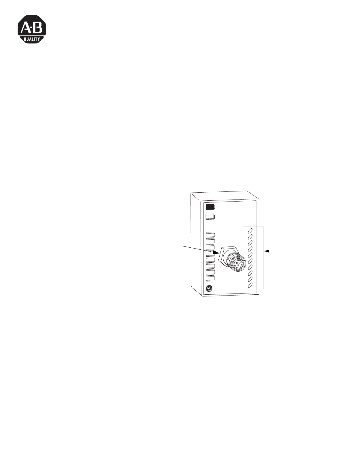
LED Indicators
43808
1738-IJM23
M23
Connector
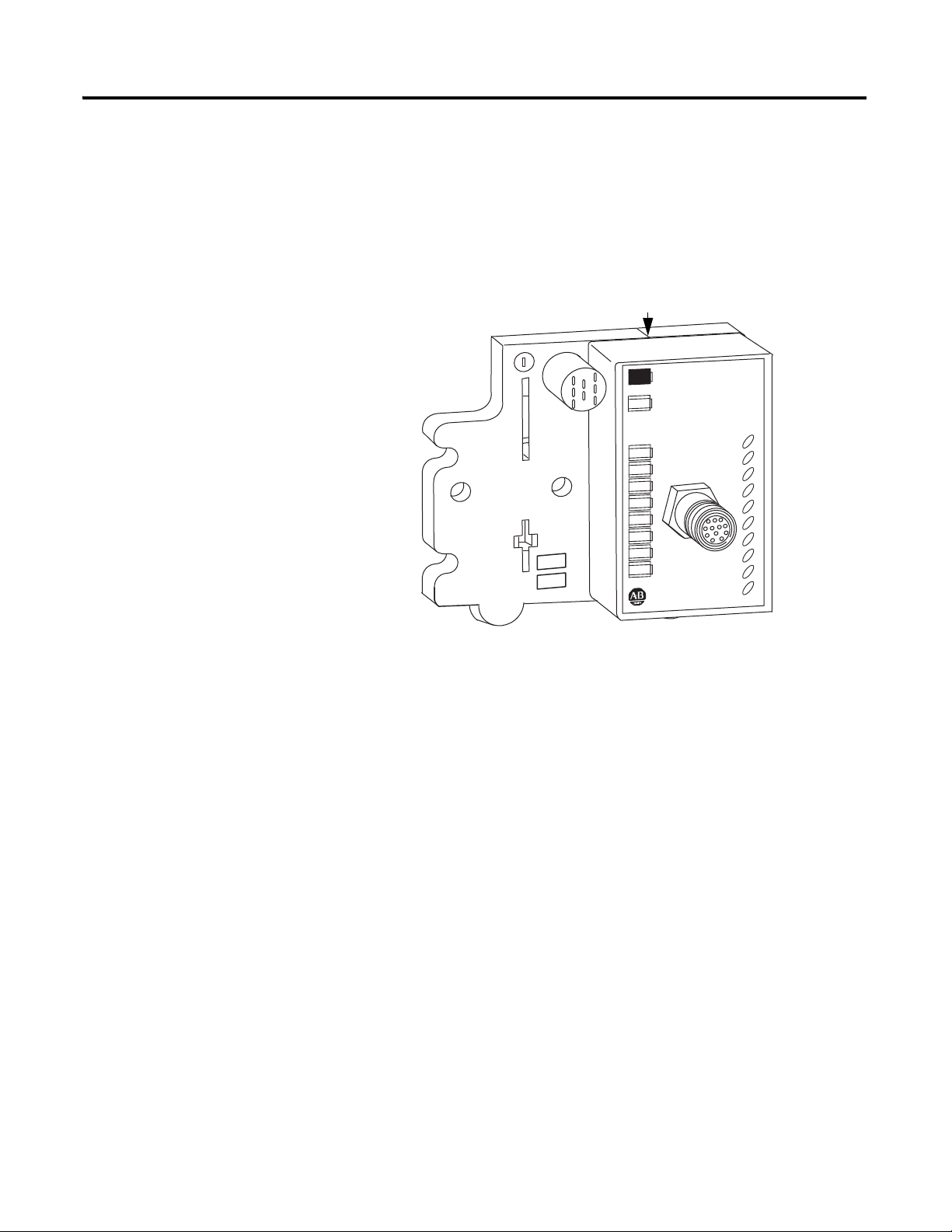
ArmorPOINT I/O 5V DC Encoder/Counter
Module, Series A
Catalog number 1738-IJM23
The ArmorPOINT® I/O family (Bulletin 1738) consists of modular I/O
modules. The sealed IP67 housing of these modules requires no enclosure.
(Note that environmental requirements other than IP67 may require an
additional appropriate housing.) The I/O connector is sealed M23 style. The
mounting base ships with the module. The 1738-IJM23 module is shown
below.
1 Publication 1738-IN012B-EN-E - August 2013
Page 2
2 ArmorPOINT I/O 5V DC Encoder/Counter Module, Series A
WARNING
IMPORTANT
ATTENTION
SHOCK HAZARD
BURN HAZARD
Important User Information
Solid state equipment has operational characteristics differing from those of electromechanical equipment. Safety
Guidelines for the Application, Installation and Maintenance of Solid State Controls (Publication
SGI-1.1 available from your
local Rockwell Automation sales office or online at http://www.rockwellautomation.com/literature/) describes some
important differences between solid state equipment and hard-wired electromechanical devices. Because of this
difference, and also because of the wide variety of uses for solid state equipment, all persons responsible for applying
this equipment must satisfy themselves that each intended application of this equipment is acceptable.
In no event will Rockwell Automation, Inc. be responsible or liable for indirect or consequential damages resulting
from the use or application of this equipment.
The examples and diagrams in this manual are included solely for illustrative purposes. Because of the many variables
and requirements associated with any particular installation, Rockwell Automation, Inc. cannot assume responsibility
or liability for actual use based on the examples and diagrams.
No patent liability is assumed by Rockwell Automation, Inc. with respect to use of information, circuits, equipment, or
software described in this manual.
Reproduction of the contents of this manual, in whole or in part, without written permission of Rockwell Automation,
Inc. is prohibited.
Throughout this manual we use notes to make you aware of safety considerations.
Identifies information about practices or circumstances that can cause an explosion in a
hazardous environment, which may lead to personal injury or death, property damage,
or economic loss.
Identifies information that is critical for successful application and understanding of the
product.
Identifies information about practices or circumstances that can lead to personal injury or
death, property damage, or economic loss. Attentions help you:
• identify a hazard
• avoid a hazard
• recognize the consequence
Labels may be located on or inside the equipment to alert people that dangerous voltage
may be present.
Labels may be located on or inside the equipment to alert people that surfaces may be
dangerous temperatures.
.
Publication 1738-IN012B-EN-E - August 2013
Page 3

ArmorPOINT I/O 5V DC Encoder/Counter Module, Series A 3
ATTENTION
Environment and Enclosure
This equipment is intended for use in overvoltage
Category II applications (as defined in IEC
publication 60664-1), at altitudes up to 2000 meters
without derating.
This equipment is considered Group 1, Class A
industrial equipment according to IEC/CISPR
Publication 11. Without appropriate precautions,
there may be potential difficulties ensuring
electromagnetic compatibility in other environments
due to conducted as well as radiated disturbance.
This equipment is supplied as "enclosed" equipment.
It should not require additional system enclosure
when used in locations consistent with the enclosure
type ratings stated in the Specifications section of this
publication. Subsequent sections of this publication
may contain additional information regarding
specific enclosure type ratings, beyond what this
product provides, that are required to comply with
certain product safety certifications.
NOTE: See NEMA Standards publication 250 and
IEC publication 60529, as applicable, for
explanations of the degrees of protection provided
by different types of enclosure. Also, see the
appropriate sections in this publication, as well as
the Allen-Bradley publication 1770-4.1 ("Industrial
Automation Wiring and Grounding Guidelines"), for
additional installation requirements pertaining to this
equipment.
Publication 1738-IN012B-EN-E - August 2013
Page 4
4 ArmorPOINT I/O 5V DC Encoder/Counter Module, Series A
ATTENTION
IMPORTANT
43769
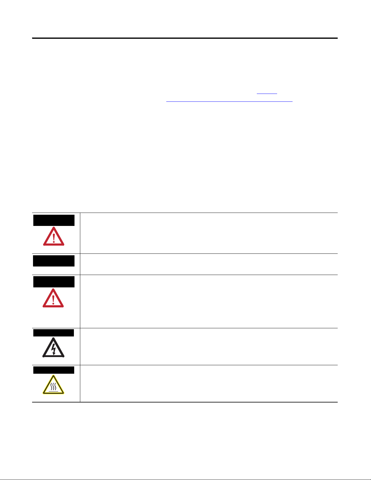
4.02 in.
102 mm
1.81 in.
46 mm
Adapter
1.9 in.
47.2 mm
2.0 in.
50 mm
0.87 in.
22 mm
2.0 in.
50 mm
0.87 in.
22 mm
2.0 in.
50 mm
Preventing Electrostatic Discharge
This equipment is sensitive to electrostatic discharge,
which can cause internal damage and affect normal
operation. Follow these guidelines when you handle
this equipment:
• Touch a grounded object to discharge potential
static.
• Wear an approved grounding wriststrap.
• Do not touch connectors or pins on component
boards.
• Do not touch circuit components inside the
equipment.
• If available, use a static-safe workstation.
• When not in use, store the equipment in
appropriate static-safe packaging.
Mount the I/O Base
To mount the ArmorPOINT I/O base on a wall or panel, use the screw holes
provided in the ArmorPOINT base.
The ArmorPOINT I/O module must be mounted on a
grounded metal mounting plate or other conductive
surface.
A mounting illustration for the ArmorPOINT base with an adapter is shown
below.
Publication 1738-IN012B-EN-E - August 2013
Page 5
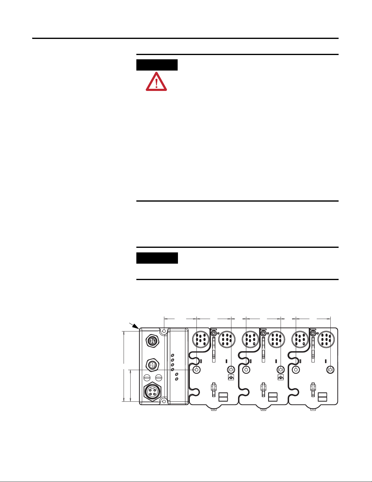
ArmorPOINT I/O 5V DC Encoder/Counter Module, Series A 5
Ground lug connection
Latching mechanism
KeyswitchSet to position 2 for
the 1738 specialty
modules
Mounting base
43675
Install the mounting base as follows:
1. Lay out the required points as shown above in the drilling dimension
drawing.
2. Drill the necessary holes for #8 (M4) machine or self-tapping screws.
3. Mount the base using #8 (M4) screws.
4. Ground the system using the ground lug connection. (The ground lug
connection is also a mounting hole.)
Publication 1738-IN012B-EN-E - August 2013
Page 6
6 ArmorPOINT I/O 5V DC Encoder/Counter Module, Series A
Module will bridge two bases.
43809
Install the ArmorPOINT Encoder/Counter Module
To install the ArmorPOINT Encoder/Counter module, proceed as follows.
1. Using a bladed screwdriver, rotate the keyswitch on the mounting base
clockwise until the number 2 aligns with the notch in the base.
2. Position the module vertically above the mounting base. The module
will bridge two bases.
1738-IJM23/A
5V dc
Encoder/Counter
MOD
NET
A
B
Z
3. Push the module down until it engages the latching mechanism. You will
hear a clicking sound when the module is properly engaged.
The locking mechanism will lock the module to the base.
Remove the ArmorPOINT Encoder/Counter Module From the
Mounting Base
To remove the module from the mounting base:
1. Put a flat blade screwdriver into the slot of the orange latching
mechanism.
2. Push the screwdriver toward the I/O module to disengage the latch.
The module will lift up off the base.
3. Pull the module off of the base.
Publication 1738-IN012B-EN-E - August 2013
Page 7

ArmorPOINT I/O 5V DC Encoder/Counter Module, Series A 7
IMPORTANT
ATTENTION
3
4
5
6
7
8
9
1010
1111
1212
2
1
43681
1738-IJM23
(view into connector)
Pin 1 - +A
Pin 2 - ~A
Pin 3 - +B
Pin 4 - ~B
Pin 5 - +Z
Pin 6 - ~Z
Pin 7 - Chassis
Pin 8 - Chassis
Pin 9 - Return (Com)
Pin 10 - Return (Com)
Pin 11 - 5V DC
Pin 12 - Chassis
Wire the Encoder/Counter Module
Following are wiring instructions for the ArmorPOINT Encoder/Counter
module.
1738-IJM23
If shielded cable is used, shield lead can be
connected to chassis pin 7, 8, or 12 on the connector.
Make sure all connectors and caps are securely
tightened to properly seal the connections against
leaks and maintain IP67 requirements.
Publication 1738-IN012B-EN-E - August 2013
Page 8

8 ArmorPOINT I/O 5V DC Encoder/Counter Module, Series A
Communicate With Your Module
I/O messages are sent to (consumed) and received from (produced) the
ArmorPOINT I/O modules. These messages are mapped into the processor’s
memory. This ArmorPOINT I/O input/output module produces 6 or 10
bytes of input data (scanner Rx - status). It consumes 1 byte of I/O data
(scanner Tx). See the 1738 ArmorPOINT adapter User Manual, publication
1734-UM016, for specific parameter information.
Default Data Map for the ArmorPOINT Encoder/Counter Module
Message size: 6 or 10 Bytes
15 14 13 12 11 10 09 08 07 06 05 04 03 02 01 00
Produces
(Scanner Rx)
P EE FNR0 O O O O 0 ZSBSASC1C0ZD0
Where: PE = Programming error
EF = EEPROM fault status
NR = Not ready status bit
ZS = Z input status
BS = B input status
AS = A input status
C = Stored data count
ZD = Zero frequency detected
LSW = Least significant word
MSW = Most significant word
Channel 0 value of present counter state (LSW)
Channel 0 value of present counter state (MSW)
Requested Poll Produce Assembly
Requested Change of State Produce Assembly
Publication 1738-IN012B-EN-E - August 2013
Note that when a configuration is sent to the module, it is checked for
consistency before being applied. If an error is found in the configuration, the
PE bit is asserted and the module retains its previous configuration. Monitor
this PE bit with your user program to isolate any problems an improperly
configured module may have. If the configuration is considered acceptable, the
counter ASIC is disabled and counting is suspended while the ASIC is loaded
with the new operational parameters.
Message size: 1 Byte
07 06 05 04 03 02 01 00
Consumes
(scanner Tx)
0 0 0 0 0 VR CP CR
Where: VR = Value reset of stored/accumulated count
CP = Counter preset
CR = Counter reset
Page 9

ArmorPOINT I/O 5V DC Encoder/Counter Module, Series A 9
Configure the Encoder/Counter Module
Parameter Set/Get Description Bytes
1 Set/Get Counter Configuration (see page 10) 1
2 Set/Get Filter Selection (see page 11) 1
3 Set/Get Decimal Position 1
4 Set/Get Reserved 1
5 Set/Get Time Base Value 2
6 Set/Get Gate Interval 1
7 Set/Get Channel Scalar (see page 11) 1
8 Set/Get Channel Rollover Value 4
9 Set/Get Channel Preset Value 4
10 Set/Get Counter Control Safe State 1
11 Set/Get Requested Poll Produce Assembly 1
12 Set/Get Requested COS Produce Assembly 1
Publication 1738-IN012B-EN-E - August 2013
Page 10

10 ArmorPOINT I/O 5V DC Encoder/Counter Module, Series A
Counter Configuration
07 06 05 04 03 02 01 00
ZI MD CF Counter 0
0 0 0 Store Count Disabled
0 0 1 Mode 1 - store/continue
0 1 0 Mode 2 - store/wait/resume
0 1 1 Mode 3 - store, reset/wait/start
0 0 0 0 Counter
0 0 0 1 Encoder X1
0 0 1 0 Encoder X2
0 0 1 1 Not used
0 1 0 0 Encoder X4
0 1 0 1 Period/Rate
0 1 1 0 Not used
0 1 1 1 Rate Measurement
1 0 0 Mode 4 - store, reset/start
1 0 1 Reserved
1 1 0 Reserved
1 1 1 Reserved
0 Z input - 0 = not inverted
1 Z input - 1 = inverted
Publication 1738-IN012B-EN-E - August 2013
Page 11

ArmorPOINT I/O 5V DC Encoder/Counter Module, Series A 11
Filter Selection
07 06 05 04 03 02 01 00
0 ZF BF AF FS
0 0 0 0 No Filter
0 0 0 1 50kHz (10μs + 0μs/-1.6μs)
0 0 1 0 5kHz (100μs + 0μs/-13.2μs)
0 1 0 0 500Hz (1.0ms + 0ms/-125μs)
1 0 0 0 50Hz (10ms + 0ms/-1.25ms)
0 A input not filtered
1 A input filtered
0 B input not filtered
1 B input filtered
0 Z input not filtered
1 Z input filtered
Scalar Selection
07 06 05 04 03 02 01 00
0 0 0 0 0 0 0 1 Z - F
0 0 0 0 0 0 1 0 Z/2 - F
0 0 0 0 0 1 0 0 Z/4 - F
0 0 0 0 1 0 0 0 Z/8 - F
0 0 0 1 0 0 0 0 Z/16 - F
0 0 1 0 0 0 0 0 Z/32 - F
0 1 0 0 0 0 0 0 Z/64 - F
1 0 0 0 0 0 0 0 Z/128 - F
1 Where Fmin indicates the frequency at which the zero frequency detect is asserted due
to counter overflow.
Scalar
min
1
= 0.149Hz
= 0.298Hz
min
= 0.596Hz
min
= 1.192Hz
min
= 2.384Hz
min
= 4.768Hz
min
= 9.537Hz
min
= 19.073Hz
min
Publication 1738-IN012B-EN-E - August 2013
Page 12

12 ArmorPOINT I/O 5V DC Encoder/Counter Module, Series A
Assemblies
The Encoder/Counter Module uses several words to communicate real time
input and output data as well as non-real time module information (i.e.,
description, revision, and so on.) and configuration. The following table shows
the words which can be exchanged. Data may be read (get) or written (set)
using an explicit message.
Instances (Dec/Hex) Services Field Bytes
#101 (0x65) Get Present Channel Data 4
#102 (0x66) Get Stored Channel Data 4
#103 (0x67) Get Present Channel Data 4
#104 (0x68) Get Programming Error Code 2
Status 2
Status 2
Stored Channel Data 4
Status 2
#105 (0x69) Set/Get Counter Control 1
#106 (0x6a) Set/Get Counter Configuration 1
Filter Selection 1
Decimal Position 1
Reserved 1
Time Base 2
Gate Interval 1
Scalar 1
Rollover Value 4
Preset Value 4
Counter Control SSV 1
#123 (0x7b) Set/Get Counter Configuration 1
Filter Selection 1
Decimal Position 1
Reserved 1
Time Base 2
Gate Interval 1
Scalar 1
Rollover Value 4
Preset Value 4
Publication 1738-IN012B-EN-E - August 2013
Counter Control SSV 1
Alignment (reserved = 0) 1
Page 13

ArmorPOINT I/O 5V DC Encoder/Counter Module, Series A 13
Module Status Indicators
43808
1738-IJM23
Network Status Indicators
I/O Status Indicators
Troubleshoot with the Indicators
1738-IJM23/A
5V dc
Encoder/Counter
MOD
NET
A
B
Z
Indication Probable Cause
Module Status
Off No power applied to device
Green Device operating normally
Flashing Green Device needs commissioning due to missing, incomplete, or
incorrect configuration
Flashing Red Recoverable fault
Red Unrecoverable fault – may require device replacement
Flashing Red/Green Device is in self-test
Publication 1738-IN012B-EN-E - August 2013
Page 14

14 ArmorPOINT I/O 5V DC Encoder/Counter Module, Series A
Indication Probable Cause
Network Status
Off Device is not online:
Flashing Green Device is online but has no connections in the established state.
Green Device is online and has connections in the established state.
Flashing Red One or more I/O connections in timed-out state.
Red Critical link failure – failed communication device. Device
Flashing Red/Green Communication faulted device – the device has detected a
Indication Probable Cause
I/O Status
Input Status
– Device has not completed dup_MAC-id test.
– Device not powered. Check module status indicator.
detected error that prevents it from communicating on the
network.
network access error and is in communication faulted state.
Device has received and accepted an Identity Communication
Faulted Request – long protocol message.
Off Input inactive
Yellow Input is active and under control
Flashing Yellow Input is toggling
Publication 1738-IN012B-EN-E - August 2013
Page 15

ArmorPOINT I/O 5V DC Encoder/Counter Module, Series A 15
Specifications
Following are specifications for the 1738 ArmorPOINT Encoder/Counter
module.
ArmorPOINTArmorPOINT 1738-IJM23 Module
Input Specifications
Number of Inputs 1 – 1 group of A/A return, B/B return, and Z/Z return
Input Voltage 5V
Input Current 19.1 mA @ 5V DC
25.7 mA @ 6V DC
Input OFF-State Voltage <1.25V DC
Input OFF-State Current, max <0.250 mA
Input ON-State Voltage >2.6V DC
Input ON-State Current >5 mA
Maximum ON-State Voltage +6V
Input Filter Selections
(per A/B/Z group)
Maximum Input Frequency 1.0 MHz counter and encoder X1 configurations
Keyswitch Position 2
General Specifications
LED Indicators 1 yellow input status, logic side
POINTBus Current, max 160 mA
Power Dissipation, max 1.1 W @ rated load
Thermal Dissipation, max 3.75 BTU/hr @ rated load
Isolation Voltage
(continuous-voltage withstand rating)
External DC Power (does not represent power
required to supply outputs)
Dimensions
(H x W x D)
Temperature, Operating IEC 60068-2-1 (Test Ad, Operating Cold),
Temperature, Nonoperating IEC 60068-2-1 (Test Ab, Unpackaged Nonoperating Cold),
Relative Humidity IEC 60068-2-30 (Test Db, Un-packaged Nonoperating Damp Heat):
Shock, Operating IEC60068-2-27 (Test Ea, Unpackaged Shock):
Shock, Nonoperating IEC60068-2-27 (Test Ea, Unpackaged Shock):
Off
10 μs
100 μs
1.0 ms
10.0 ms
500 kHz encoder X2 configuration (no filter)
250 kHz encoder X4 configuration (no filter)
1 green/red network status, logic side
1 green/red module status, logic side
50V rms
Tested @ 1250V AC rms for 60s
No additional external power required to power module
31.75 x 66.80 x 107.95 mm
(1.25 x 2.63 x 4.25 in.)
IEC 60068-2-2 (Test Bd, Operating Dry Heat),
IEC 60068-2-14 (Test Nb, Operating Thermal Shock):
-20...60°C (-4...140°F)
IEC 60068-2-2 (Test Bb, Unpackaged Nonoperating Dry Heat),
-40...85°C (-40...185°F)
5...95% noncondensing
30g
50g
Publication 1738-IN012B-EN-E - August 2013
Page 16

16 ArmorPOINT I/O 5V DC Encoder/Counter Module, Series A
General Specifications (continued)
Vibration IEC60068-2-6 (Test Fc, Operating):
5g @ 10...500Hz
ESD Immunity IEC 61000-4-2:
6kV contact discharge
8kV air discharge
Radiated RF Immunity IEC 61000-4-3:
10V/m with 1kHz sine-wave 80% AM from 80...2700 MHz
10V/m with 200Hz 50% Pulse 100% AM from 900...1890 Mhz
EFT/B Immunity IEC 61000-4-4:
±2 kV @ 5.0 kHz on signal ports
Surge Transient Immunity IEC 61000-4-5:
±1 kV line-line (DM) and ±2 kV line-earth (CM) on signal ports
Conducted RF Immunity IEC 61000-4-6:
10V rms with 1 kHz sine-wave 80% AM from 150 kHz...80MHz
Emissions CSPR 11:
Group 1, Class A
Enclosure Type Rating Meets IP65/66/67 (when marked)
Mounting Base Screw Torque #8 screw:
0.847 Nm – Aluminum
1.807 Nm – Steel
Weight (approx.) 0.289 kg
(0.637 lb.)
Wiring Category
1
Certifications:
(when product is marked)
2 - on signal ports
c-UL-us UL Listed Industrial Control Equipment, certified for US and Canada
3
CE
European Union 2004/108/EC EMC Directive, compliant with:
EN 61000-6-2; Industrial Immunity
EN 61000-6-4; Industrial Emissions
EN 61131-2; Programmable Controllers (Clause 8, Zone A & B)
EN 61326-1; Meas./Control/Lab., Industrial Requirements
C-Tick3Australian Radiocommunications Act, compliant with:
AS/NZS CISPR 11; Industrial Emissions
1. Use this Conductor Category information for planning conductor routing. Refer to Industrial Automation Wiring and Grounding
Guidelines, publication
1770-IN041, for additional installation requirements.
2. See the Product Certification link at http://www.rockwellautomation.com/products/certification/ for Declarations of Conformity,
Certificates, and other certification details.
Publication 1738-IN012B-EN-E - August 2013
Page 17

Notes:
ArmorPOINT I/O 5V DC Encoder/Counter Module, Series A 17
Publication 1738-IN012B-EN-E - August 2013
Page 18

Rockwell Automation Support
Rockwell Automation provides technical information on the web to assist you in using our products. At
http://www.rockwellautomation.com/support/, you can find technical manuals, a knowledge base of FAQs, technical and
application notes, sample code and links to software service packs, and a MySupport feature that you can customize to make the
best use of these tools.
For an additional level of technical phone support for installation, configuration and troubleshooting, we offer TechConnect
Support programs. For more information, contact your local distributor or Rockwell Automation representative, or visit
http://www.rockwellautomation.com/support/
Installation Assistance
If you experience a problem with a hardware module within the first 24 hours of installation, please review the
information that's contained in this manual. You can also contact a special Customer Support number for initial help
in getting your module up and running:
United States 1.440.646.3223
Monday – Friday, 8am – 5pm EST
Outside United States Please contact your local Rockwell Automation representative for any technical support issues.
.
New Product Satisfaction Return
Rockwell tests all of our products to ensure that they are fully operational when shipped from the manufacturing
facility. However, if your product is not functioning and needs to be returned:
United States Contact your distributor. You must provide a Customer Support case number (see phone number
above to obtain one) to your distributor in order to complete the return process.
Outside United States Please contact your local Rockwell Automation representative for return procedure.
ArmorPOINT is a trademark of Rockwell Automation.
Publication 1738-IN012B-EN-E - August 2013 18
Copyright © 2013 Rockwell Automation, In c. All rights reserved. Printed in the U.S.A.
 Loading...