

Page 1
Installation Instructions
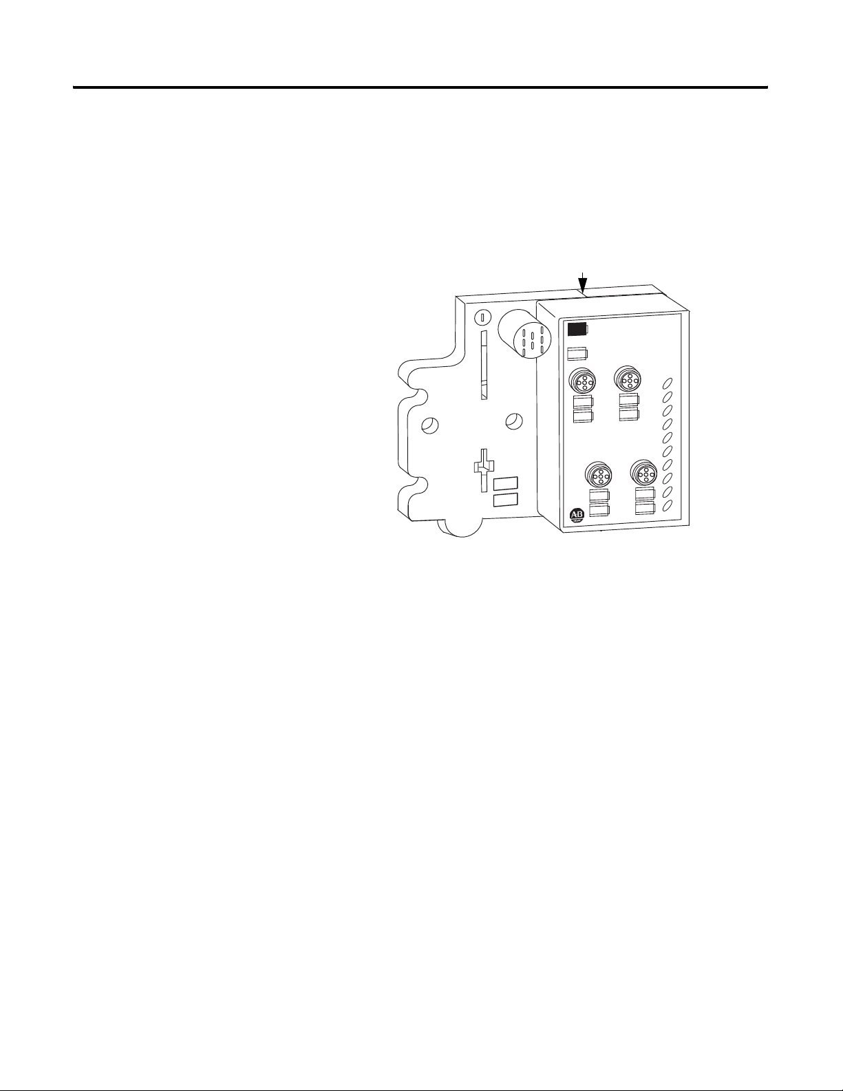
ArmorPoint 24V dc 4-channel Digital Input
Module with Diagnostics
Catalog Number 1738-IB4DM12
The ArmorPoint™ I/O family consists of modular I/O modules. The sealed
IP67 housing of these modules requires no enclosure. (Note that
environmental requirements other than IP67 may require an additional
appropriate housing.) I/O connectors are sealed M8 (pico), M12 (micro) or
M23 styles. The mounting base ships with the module.
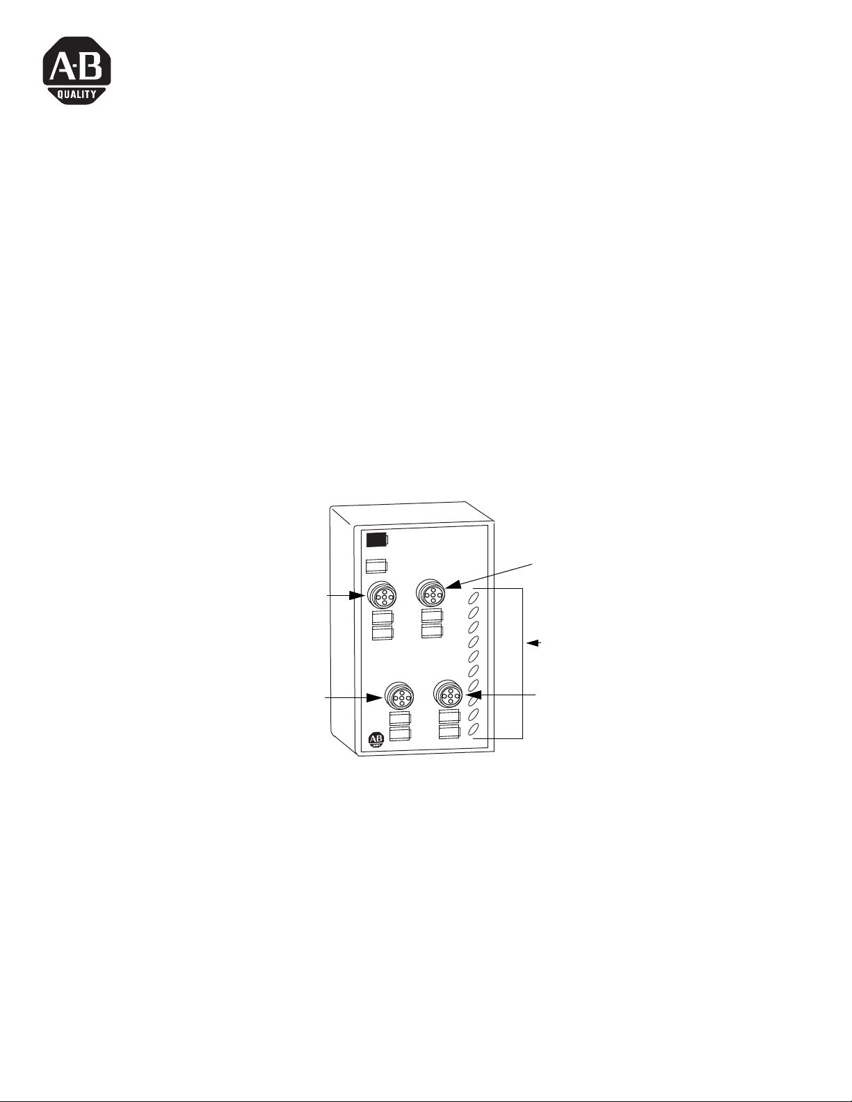
Connector M12-A
Connector M12-C
1738-IB4DM12
24V dc In with
Diagnostics
0
IO Diagnostics:
Solid Red = Short
Flashing Red = Open
2
Connector M12-B
1
MOD
NET
LED Indicators
0
3
1
2
3
Connector M12-D
43680
1 Publication 1738-IN021A-EN-E - January 2007
Page 2
2 ArmorPoint 24V dc 4-channel Digital Input Module with Diagnostics
Important User Information
Solid state equipment has operational characteristics differing from those of electromechanical equipment. Safety Guidelines
for the Application, Installation and Maintenance of Solid State Controls (publication SGI-1.1 available from your local
Rockwell Automation sales office or online at
http://literature.rockwellautomation.com) describes some important differences
between solid state equipment and hard-wired electromechanical devices. Because of this difference, and also because of the
wide variety of uses for solid state equipment, all persons responsible for applying this equipment must satisfy themselves
that each intended application of this equipment is acceptable.
In no event will Rockwell Automation, Inc. be responsible or liable for indirect or consequential damages resulting from the use
or application of this equipment.
The examples and diagrams in this manual are included solely for illustrative purposes. Because of the many variables and
requirements associated with any particular installation, Rockwell Automation, Inc. cannot assume responsibility or liability for
actual use based on the examples and diagrams.
No patent liability is assumed by Rockwell Automation, Inc. with respect to use of information, circuits, equipment, or software
described in this manual.
Reproduction of the contents of this manual, in whole or in part, without written permission of Rockwell Automation, Inc., is
prohibited.
Throughout this manual, when necessary, we use notes to make you aware of safety considerations.
WARNING
Identifies information about practices or circumstances that can cause an explosion in a hazardous
environment, which may lead to personal injury or death, property damage, or economic loss.
IMPORTANT
ATTENTION
SHOCK HAZARD
BURN HAZARD
Identifies information that is critical for successful application and understanding of the product.
Identifies information about practices or circumstances that can lead to personal injury or death, property
damage, or economic loss. Attentions help you to identify a hazard, avoid a hazard, and recognize the
consequences.
Labels may be located on or inside the equipment, for example, a drive or motor, to alert people that
dangerous voltage may be present.
Labels may be located on or inside the equipment, for example, a drive or motor, to alert people that
surfaces may be dangerous temperatures.
.
Publication 1738-IN021A-EN-E - January 2007
Page 3
ArmorPoint 24V dc 4-channel Digital Input Module with Diagnostics 3
ATTENTION
Environment and Enclosure
This equipment is intended for use in overvoltage Category II
applications (as defined in IEC publication 60664-1), at altitudes up to
2000 meters without derating.
This equipment is considered Group 1, Class A industrial equipment
according to IEC/CISPR Publication 11. Without appropriate
precautions, there may be potential difficulties ensuring
electromagnetic compatibility in other environments due to conducted
as well as radiated disturbance.
This equipment is supplied as "enclosed" equipment. It should not
require additional system enclosure when used in locations
consistent with the enclosure type ratings stated in the Specifications
section of this publication. Subsequent sections of this publication
may contain additional information regarding specific enclosure type
ratings, beyond what this product provides, that are required to
comply with certain product safety certifications.
NOTE: See NEMA Standards publication 250 and IEC publication
60529, as applicable, for explanations of the degrees of protection
provided by different types of enclosure. Also, see the appropriate
sections in this publication, as well as the Allen-Bradley publication
1770-4.1 ("Industrial Automation Wiring and Grounding Guidelines"),
for additional installation requirements pertaining to this equipment.
ATTENTION
Preventing Electrostatic Discharge
This equipment is sensitive to electrostatic discharge, which can
cause internal damage and affect normal operation. Follow these
guidelines when you handle this equipment:
• Touch a grounded object to discharge potential static.
• Wear an approved grounding wriststrap.
• Do not touch connectors or pins on component boards.
• Do not touch circuit components inside the equipment.
• If available, use a static-safe workstation.
• When not in use, store the equipment in appropriate static-safe
packaging.
Publication 1738-IN021A-EN-E - January 2007
Page 4
4 ArmorPoint 24V dc 4-channel Digital Input Module with Diagnostics
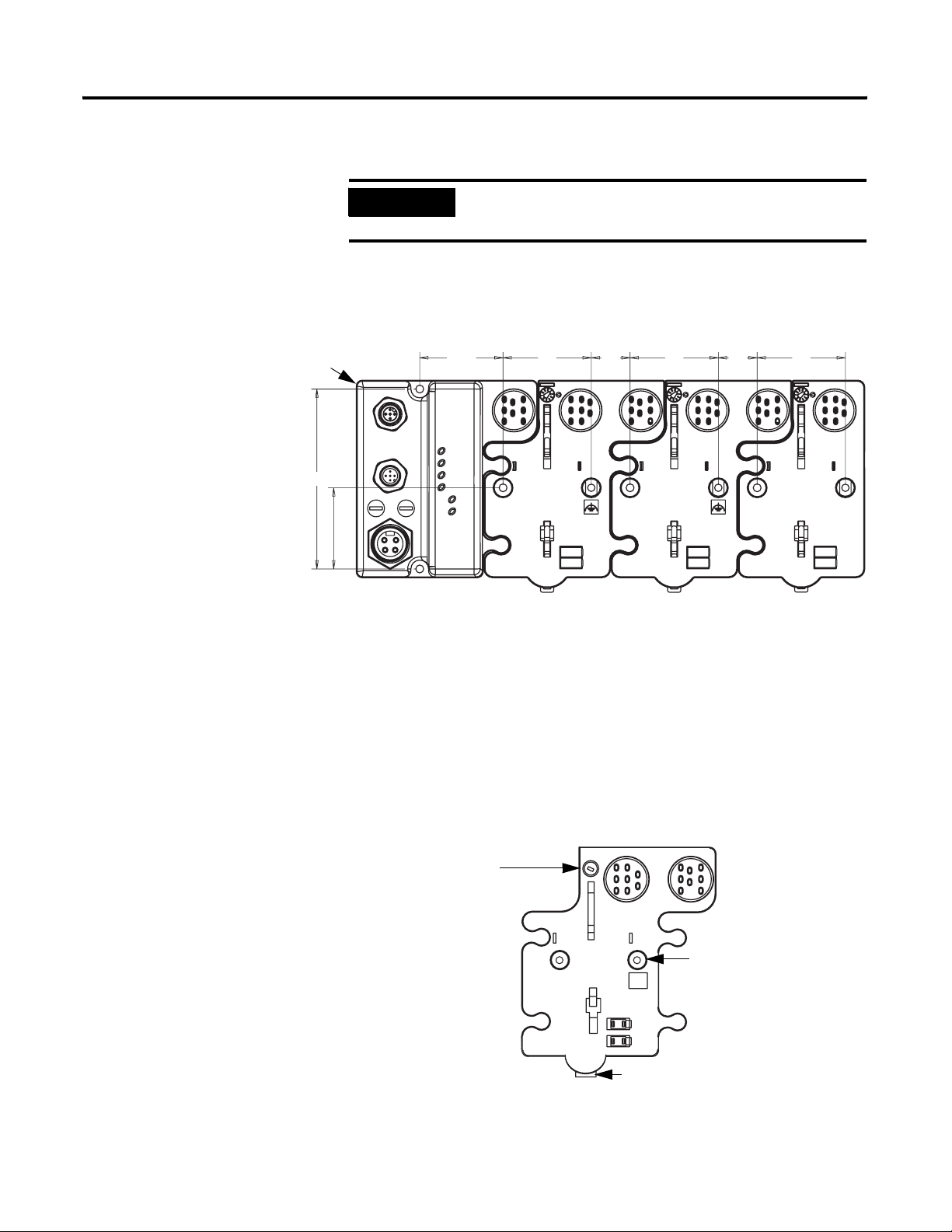
Mount the I/O Base
To mount the base on a wall or panel, use the screw holes provided in the base.
A drilling dimensions mounting illustration for the base with an adapter is
shown below.
Drilling Dimensions
Adapter
4.02 in.
102 mm
1.81 in.
46 mm
IMPORTANT
The module must be mounted on a grounded metal mounting
plate or other conductive surface.
1.9 in.
47.2 mm
2.0 in.
50 mm
0.87 in.
22 mm
2.0 in.
50 mm
0.87 in.
22 mm
2.0 in.
50 mm
43769
Install the mounting base as follows:
1. Lay out the required points as shown in the drilling dimension drawing.
2. Drill the necessary holes for #8 (M4) machine or self-tapping screws.
3. Mount the base using #8 (M4) screws.
4. Ground the system using the ground lug connection. (The ground lug
connection is also a mounting hole.)
Mounting base
Ground lug connection
43675
Latching mechanism
Publication 1738-IN021A-EN-E - January 2007
Page 5
ArmorPoint 24V dc 4-channel Digital Input Module with Diagnostics 5
Install the Digital Input Module
To install the digital input module:
1. Using a bladed screwdriver, rotate the keyswitch on the mounting base
clockwise until the number 1 aligns with the notch in the base.
2. Position the module vertically above the mounting base. The module
will bridge two bases.
Module will bridge two bases.
1738-IB4DM12
24V dc In with
Diagnostics
0
1
IO Diagnostics:
Solid Red = Short
Flashing Red = Open
2
3
MOD
NET
0
1
2
3
43772
3. Push the module down until it engages the latching mechanism. You will
hear a clicking sound when the module is properly engaged.
The locking mechanism will lock the module to the base.
Remove the Module From the Mounting Base
To remove the module from the mounting base:
1. Put a flat blade screwdriver into the slot of the orange latching
mechanism.
2. Push the screwdriver toward the module to disengage the latch.
The module will lift up off the base.
3. Pull the module off of the base.
Publication 1738-IN021A-EN-E - January 2007
Page 6

6 ArmorPoint 24V dc 4-channel Digital Input Module with Diagnostics
Understand Short-circuit Detection
Understand Open-wire Detection
The sensor source voltage (SSV) for each input is protected against short
circuits. For currents above 200 mA, a fault signal is issued and the input LED
indicator is illuminated solid red. A thermally-actuated smart-power device or
PTC is used as the protection means. On a per-input basis, the circuit and
produced data automatically reset and SSV energizes upon removal of the
short circuit. An individual fault signal is issued for each shorted SSV
condition.
The shorted input LED indicator illuminates red to denote short-circuit fault
status.
See the section on interpreting LED indicators for related information.
When the SSV is loaded to the maximum rated current of 50 mA, a voltage
drop of as much as 2.5V dc can exist between the user auxiliary power and the
SSV connection. For example, for a supply of 10V dc to a sensor with power
derived from the SSV, a supply of 12.5V dc is needed at the auxiliary power
connection.
Sensor source voltage (SSV) current for each input is monitored. Monitoring is
accomplished in the SSV leg to accommodate the largest number of sensors
possible. For currents below 0.5 mA, a fault signal is issued and the input's
LED indicator blinks red. On a per-input basis, the circuit and produced data
automatically reset upon removal of the open-wire condition. See the
information about interpreting LED indicators for related information.
By using a configuration tool, you can disable the open- wire diagnostics on an
input-point basis to keep unused input indicators from turning red and
signaling a fault when an input is not in use. Enabling or disabling input-point
level open-wire diagnostics is implemented via the module’s EDS file, GSD
file, or Logix profile and its firmware.
You can also disable all the open-wire diagnostics, using a single entry via the
software user interface. The default configuration has all four input channels’s
open-wire indication enabled.
If a sensor with a dry contact output is used, wire one side of the contact to
the SSV terminal for the corresponding input. Wire the other side of the
contact to the input. Additionally, place a shunt resistor in parallel with the
contact, at the sensor, to cause greater than 0.5 mA to be drawn through the
SSV terminal at all times.
Publication 1738-IN021A-EN-E - January 2007
Page 7

ArmorPoint 24V dc 4-channel Digital Input Module with Diagnostics 7
Wire the Module
Following are wiring instructions for the module.
ATTENTION
Make sure all connectors and caps are securely tightened to properly
seal the connections against leaks and maintain IP enclosure type
requirements.
To comply with the CE Low Voltage Directive (LVD), all connected I/O
must be powered from a source compliant with the following:
• Safety Extra Low Voltage (SELV) or Protected Extra Low
Voltage (PELV).
1738-IB4DM12
(view into connector)
Pin 1 - 24V dc (Sensor Source Voltage SSV)
Pin 2 - No Connect
Pin 3 - Common
Pin 4 - Input 0 (M12-A)
Input 1 (M12-B)
Input 2 (M12-C)
43664
Input 3 (M12-D)
Pin 5 - No Connect
Communicate With Your Module
I/O messages are sent to (consumed) and received from (produced) the
module. These messages are mapped into the processor’s or scanner’s memory.
The module produces 1 or 2 bytes of input data (scanner Rx - status) based on
which produced assembly is selected. The default setup is 2 bytes.
Default Data Map - Produced Assembly Instance 101
Message Size: 2 Bytes
7 6 5 4 3 2 1 0
Produce 0 (Rx) Fault 3Fault 2Fault 1Fault 0Input 3Input 2Input 1Input
0
Produce 1 (Rx) SC 3 SC 2 SC 1 SC 0 OW 3 OW 2 OW 1 OW 0
Consume (Tx) No consumed data
Where: 0W = open wire, SC = short circuit, fault = open wire or short circuit.
Publication 1738-IN021A-EN-E - January 2007
Page 8

8 ArmorPoint 24V dc 4-channel Digital Input Module with Diagnostics
Data Map - Produced Assembly Instance 23
Message Size: 1 Bytes
Produce 0 (Rx) Fault 3Fault 2Fault 1Fault 0Input 3Input 2Input 1Input
Consume (Tx) No consumed data
Where: Fault = open wire or short circuit.
Default Data Map - Configuration Assembly Instance 103
Message Size: 18 Bytes
Consume 0 Input 0 Off to On Filter Byte 0
7 6 5 4 3 2 1 0
0
7 6 5 4 3 2 1 0
Consume 1 Input 0 Off to On Filter Byte 1
Consume 2 Input 0 On to Off Filter Byte 0
Consume 3 Input 0 On to Off Filter Byte 1
Consume 4 Input 1 Off to On Filter Byte 0
Consume 5 Input 1 Off to On Filter Byte 1
Consume 6 Input 1 On to Off Filter Byte 0
Consume 7 Input 1 On to Off Filter Byte 1
Consume 8 Input 2 Off to On Filter Byte 0
Consume 9 Input 2 Off to On Filter Byte 1
Consume 10 Input 2 On to Off Filter Byte 0
Consume 11 Input 2 On to Off Filter Byte 1
Consume 12 Input 3 Off to On Filter Byte 0
Consume 13 Input 3 Off to On Filter Byte 1
Consume 14 Input 3 On to Off Filter Byte 0
Consume 15 Input 3 On to Off Filter Byte 1
Consume 16 Autobaud
Disabled
Enable
OW3
Enable
OW3
Enable
OW3
Enable
OW3
Publication 1738-IN021A-EN-E - January 2007
Consume 17 Produced Assembly Instance
Produce (Tx) No produced data
Where: OW = open wire.
Page 9

ArmorPoint 24V dc 4-channel Digital Input Module with Diagnostics 9
Troubleshoot With the Indicators
1738-IB4DM12
1738-IB4DM12
24V dc In with
Diagnostics
0
1
IO Diagnostics:
Solid Red = Short
Flashing Red = Open
2
3
MOD
Module Status Indicators
NET
0
1
2
3
Network Status Indicators
Interpret LED Indicators
Indication Probable Cause Recommended Action
Module Status
I/O Status Indicators
43680
Off No power applied to device Apply power to device.
Green Device operating normally None.
Flashing Green Device needs commissioning due to configuration
Configure device properly.
missing, incomplete or incorrect.
Flashing Red Recoverable fault 1. Cycle power to device.
2. If condition persists, replace device.
Red Unrecoverable fault - may require device
Replace device.
replacement
Flashing Red/Green Device is in self-test None.
Network Status
Off Device is not on line:
- Device has not completed dup_MAC_ID test.
- Device not powered - check module status
Apply power to device, wait for
dup_MAC_id to complete, and correct, as
needed.
indicator.
Flashing Green Device is on line but has no connections in the
None - device is in Idle or Program mode.
established state.
Green Device is on line and has connections in the
None.
established state.
Flashing Red One or more I/O connections in timed-out state. Check for I/O module failure, and correct, as
needed.
Publication 1738-IN021A-EN-E - January 2007
Page 10

10 ArmorPoint 24V dc 4-channel Digital Input Module with Diagnostics
Indication Probable Cause Recommended Action
Red Critical link failure - failed communication device.
Device detected error that prevents it from
Verify that adapter and terminal bases are
properly installed, and reinstall, as needed.
communicating on the network.
Flashing Red/Green Communication faulted device - the device has
detected a network access error and is in
Verify that adapter is properly installed, and
reinstall, as needed.
communication faulted state. Device has received
and accepted an Identity Communication Faulted
Request - long protocol message.
I/O Status
Off Input is in the off state. None.
Yell ow Input is in the on state. None.
Red Short circuit detected. Check I/O wiring.
Flashing Red Open wire detected. Check I/O wiring.
Publication 1738-IN021A-EN-E - January 2007
Page 11

ArmorPoint 24V dc 4-channel Digital Input Module with Diagnostics 11
Specifications
Following are specifications for the ArmorPoint 24V dc 4-channel Digital
Input Module.
ArmorPoint 24V dc 4-channel Digital Input Module
General Specifications
Inputs 4 (1 group of 4) nonisolated, sinking
Voltage, Off-State Input, Maximum 5V dc
Voltage, On-State Input
Maximum
Minimum
Nominal
28.8V dc
11V dc
24V dc
Current, Off-State Input, Maximum 1.5 mA
Current, On-State Input
Maximum
Minimum
Nominal
Input Delay Time OFF to ON
15 mA
2 mA
3 mA @ 24V dc
0-65535 us selectable
(3)
in 1 us intervals (rounded to nearest 333 us)
Default is 1000 us.
Input Delay Time, ON to OFF
0-65535 us selectable
(4)
in 1 us intervals (rounded to nearest 333 us)
Default is 1000 us.
Field Power Bus Supply
Voltage Range
Nominal
10-28.8V dc
24V dc
Keyswitch Position 1
Reverse Polarity Protection Yes
LED Indicators 1 green/red network status, logic side
1 green/red module status, logic side
4 yellow/red input status, logic side
PointBus Current, Maximum 50 mA @ 5V dc
Power Dissipation, Maximum 0.6W max @ 28.8V dc
Thermal Dissipation, Maximum 1.9BTU/hr max @ 28.8V dc
Isolation Voltage
(continuous-voltage withstand rating)
50V (continuous), Reinforced Insulation Type
Tested at 1000V dc for 60s, field-side to system
Dimensions
Imperial
Metric
4.72H x 2.83W x 1.65D (Includes I/O module and mounting base)
120H x 72W x 42D (Includes I/O module and mounting base)
Enclosure Type Rating Meets IP65/66/67/69k (when marked)
Mounting Base Screw Torque #8 screw, 7.5 in. lbs. in Aluminum, 16 in. lbs. in Steel
Weight
Imperial
Metric
Wiring Category
(1)
0.64 lb.
0.29 kg
1 - on signal ports
Publication 1738-IN021A-EN-E - January 2007
Page 12

12 ArmorPoint 24V dc 4-channel Digital Input Module with Diagnostics
ArmorPoint 24V dc 4-channel Digital Input Module
Environmental Specifications
Operating Temperature IEC 60068-2-1 (Test Ad, Operating Cold),
IEC 60068-2-2 (Test Bd, Operating Dry Heat),
IEC 60068-2-14 (Test Nb, Operating Thermal Shock):
-20 to 60°C (-4 to 140°F)
Storage Temperature IEC 60068-2-1 (Test Ab, Un-packaged Non-operating Cold),
IEC 60068-2-2 (Test Bb, Un-packaged Non-operating Dry Heat),
-40 to 85°C (-40 to 185°F)
Relative Humidity IEC 60068-2-30 (Test Db, Un-packaged Damp Heat):
5-95% non-condensing
Shock IEC60068-2-27 (Test Ea, Unpackaged Shock):
Operating 30g
Non-operating 50g
Vibration IEC60068-2-6 (Test Fc, Operating):
5g @ 10-500Hz
ESD Immunity IEC 61000-4-2:
6kV contact discharges
8kV air discharges
Radiated RF Immunity IEC 61000-4-3:
10V/m with 1kHz sine-wave 80%AM from 30MHz to 2000MHz
10V/m with 200Hz 50% Pulse 100%AM at 900Mhz
10V/m with 200Hz 50% Pulse 100%AM at 1890Mhz
1V/m with 1 kHz sine-wave 80%AM from 2000 to 2700Mhz
EFT/B Immunity IEC 61000-4-4:
±3kV at 5kHz on signal ports
Surge Transient Immunity IEC 61000-4-5:
±1kV line-line(DM) and ±2kV line-earth(CM) on signal ports
Conducted RF Immunity IEC 61000-4-6:
10Vrms with 1kHz sine-wave 80%AM from 150kHz to 80MHz
Emissions CSPR 11:
Group 1, Class A
Publication 1738-IN021A-EN-E - January 2007
Page 13

ArmorPoint 24V dc 4-channel Digital Input Module with Diagnostics 13
ArmorPoint 24V dc 4-channel Digital Input Module
Environmental Specifications (continued)
Certifications
Certifications:
(2)
(when product is marked)
CE European Union 89/336/EEC EMC Directive,
compliant with:
EN 50082-2; Industrial Immunity
EN 61326; Meas./Control/Lab., Industrial Requirements
EN 61000-6-2; Industrial Immunity
EN 61000-6-4; Industrial Emissions
EN 61131-2; Programmable Controllers (Clause 8, Zone A & B)
C-Tick Australian Radiocommunciations Act, compliant with:
AS/NZS CISPR 11; Industrial Emissions
(1)
Use this Conductor Category information for planning conductor routing. Refer to Publication 1770-4.1, "Industrial Automation Wiring and Grounding Guidelines".
(2)
See the Product Certification link at www.ab.com for Declarations of Conformity, Certificates, and other certification details.
(3)
Input OFF to ON or ON to OFF delay is time from a valid input signal to recognition by the module.
(4)
Input OFF to ON or ON to OFF delay is time from a valid input signal to recognition by the module.
Publication 1738-IN021A-EN-E - January 2007
Page 14

Rockwell Automation Support
Rockwell Automation provides technical information on the web to assist you in using its products. At
http://support.rockwellautomation.com, you can find technical manuals, a knowledge base of FAQs, technical and application
notes, sample code and links to software service packs, and a MySupport feature that you can customize to make the best use of
these tools.
For an additional level of technical phone support for installation, configuration and troubleshooting, we offer TechConnect
Support programs. For more information, contact your local distributor or Rockwell Automation representative, or visit
http://support.rockwellautomation.com.
Installation Assistance
If you experience a problem with a hardware module within the first 24 hours of installation, please review the information that's
contained in this manual. You can also contact a special Customer Support number for initial help in getting your module up and
running:
United States 1.440.646.3223
Monday – Friday, 8am – 5pm EST
Outside United States Please contact your local Rockwell Automation representative for any technical support
issues.
New Product Satisfaction Return
Rockwell tests all of its products to ensure that they are fully operational when shipped from the manufacturing facility. However, if
your product is not functioning and needs to be returned:
United States Contact your distributor. You must provide a Customer Support case number (see phone
number above to obtain one) to your distributor in order to complete the return process.
Outside United States Please contact your local Rockwell Automation representative for return procedure.
Publication 1738-IN021A-EN-E - January 2007 14 PN 953014-84
Copyright © 2007 Rockwell Automation, In c. All rights reserved. Printed in the U.S.A.
 Loading...