

Page 1
Installation Instructions
POINT I/O Wiring Base Assembly
(Cat. No. 1734-TB and -TBS)
6
3
2
4
5
1
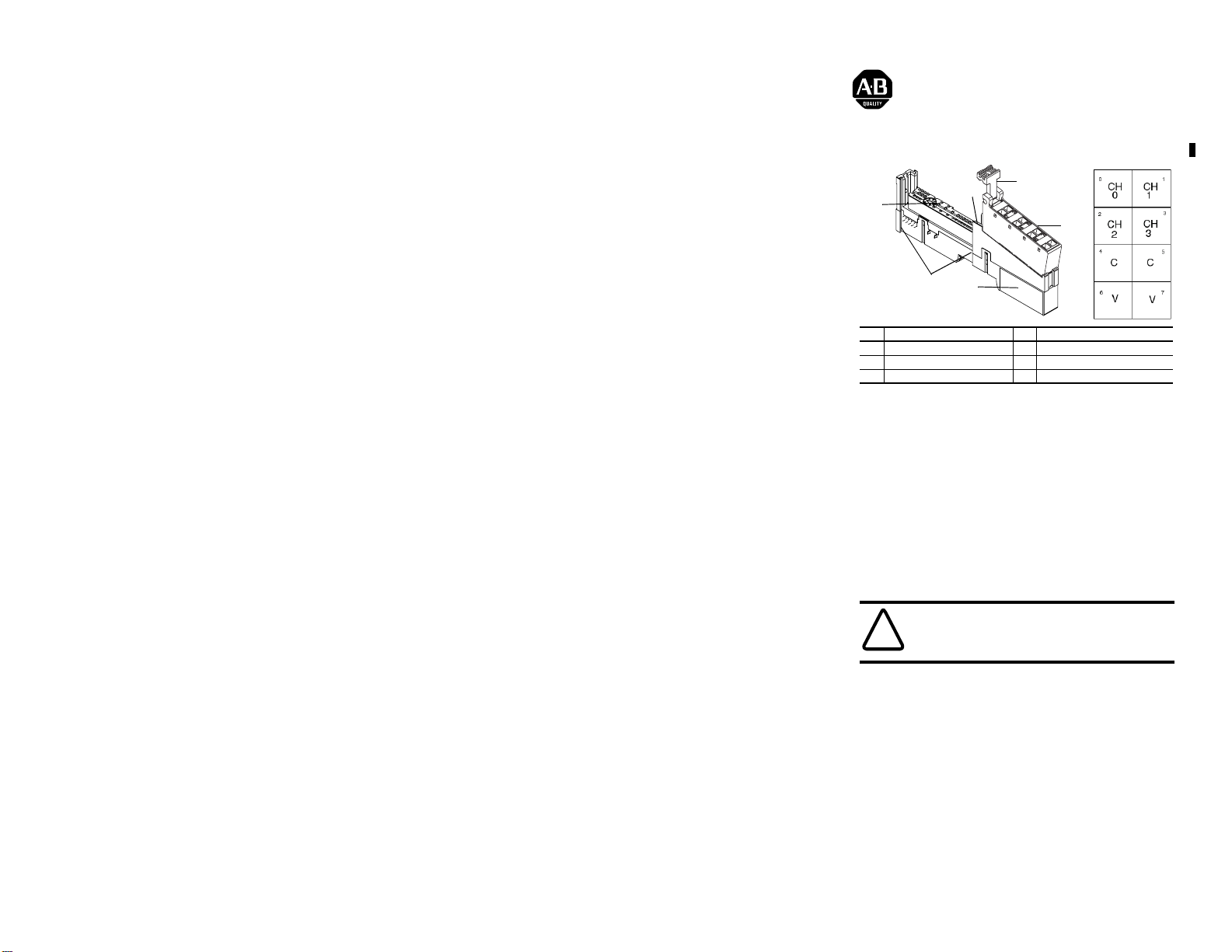
Description Description
1 Wiring Base 4 Removable Wiring Block (RTB
2 Mechanical Keying (orange) 5 Interlocking Side Pieces
3 RTB Removal Handle 6 DIN Rail Locking Screw (orange)
The wiring base consists of a base (1) and a removable terminal block (RTB)(4). The
1734-TB uses screw-clamp termination; 1734-TBS uses spring-clamp terminations.
Installing the Wiring Base
To install the wiring base on the DIN rail, proceed as follows.
1. Position the wiring base vertically above the installed units (adapter, power
supply or existing module.
2. Slide the wiring base down allowing the interlocking side pieces to engage the
adjacent module or adapter.
3. Press firmly to seat the wiring base on the DIN rail. The wiring base will snap
into place.
4. To remove the wiring base from the DIN rail, remove the module, and use a
small bladed screwdriver to r ota te the base locking scr ew to a vertical position.
This releases the locking mechanism. Then lift straight up to remove.
Installing the Removable Terminal Block
A removable terminal block is supplied with your terminal base. To remove, pull up
on the RTB removal handle.
WARNING: Explosion Hazard - Do not disconnect or replace
component unless power is switched off or area is known to be
nonhazardous. Do not pull on the installed wiring to remove a terminal
!
block. A shock hazard exists if power is applied to the terminal block.
POINT I/O is a trademark of Rockwell Automation Publication 1734-IN511B-EN-P -March 2001
Page 2
2 POINT I/O Wiring Base Assembly
This allows the base to be removed and replaced as necessary without removing
any of the wiring. To reinsert the removable terminal block, proceed as follows..
1. Insert the end opposite the handle into the base unit. This end has a curved
section that engages the wiring base.
2. Rotate the terminal block into the wiring base until it locks itself in place.
3. If an I/O module is installed, snap the RTB handle into place on the module.
Removing a Wiring Base
In order to remove a wiring base, you must remove any module installed in the
base, and any installed module to the right of the base, and remove the removable
terminal block (if wired).
1. Remove the removable terminal block.
2. Squeeze the module locking mechanism and pull up to remove the
module(s).
3. Turn the wiring base locking screw to a vertical position to unlock the base
from the DIN rail.
4. Slide the wiring base up to release it from its mating units.
Refer to the user manual for keying information, specifications and how to
configure your module.
.
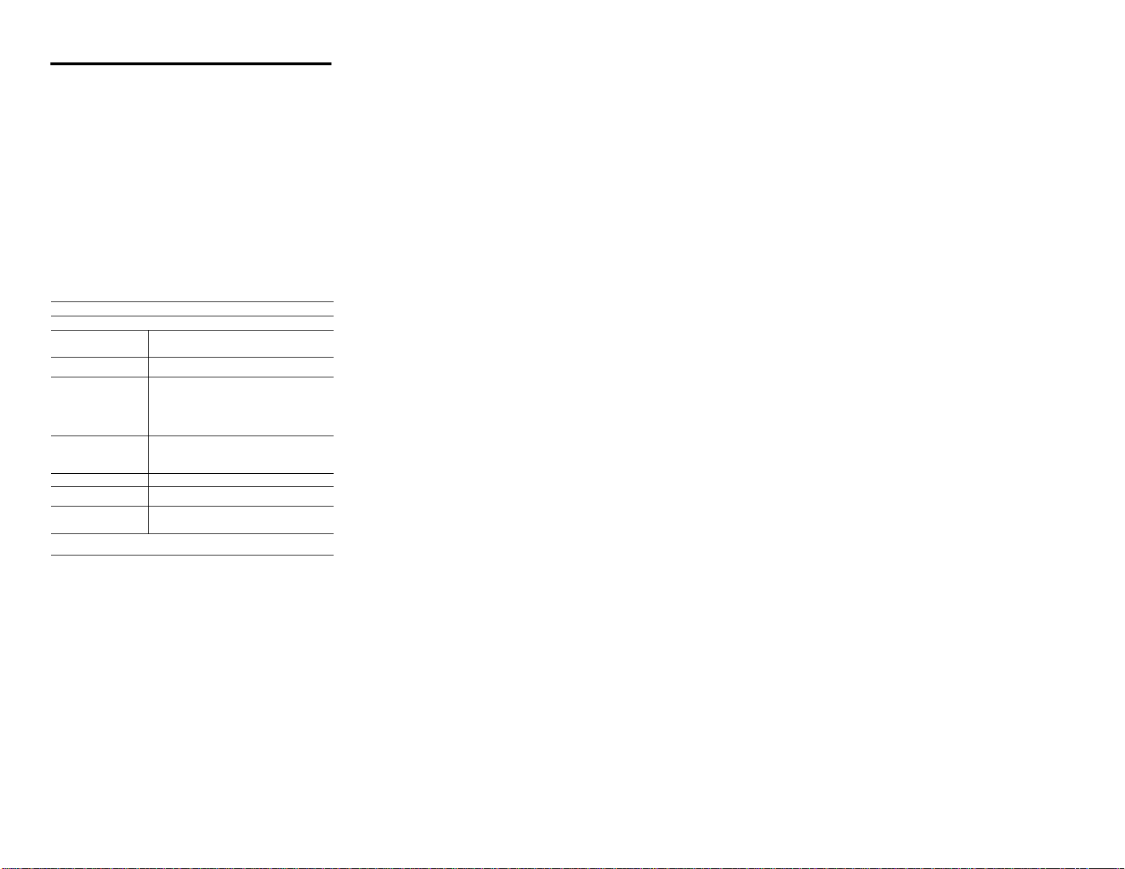
Specifications - 1734-TB (screw-clamp) and -TBS (spring-clamp)
General Specificatio ns
Field Power Bus
Supply Voltage
Supply Current
Dimensions Inches
Environmental Conditions
Operational Temperature
Storage Temperature
Relative Humidity
Shock Operating
Vibration
Conductors Wire Size
Terminal Base Screw Torque 7 pound-inches (0.6Nm)
Mass 1734-TB - 2.94 oz/83.8 grams
Agency Certification (when product
is marked)
1 Use this conductor category information for pl anning conductor routing as described in publi cation
(Millimeters)
Non-operating
1770-4.1, “Industrial Automation Wiring and Grounding Guidelines.”
28.8V dc, 120/240V ac
10A maximum
2.56H x 0.472W x 5.25L
(65H x 12W x 133.4L)
-20 to 55
-40 to 85
5 to 95% noncondensing
30g peak acceleration, 11(±1)ms pulse width
50g peak acceleration, 11(±1)ms pulse width
Tested 5g @ 10-500Hz per IEC 68-2-6
14 AWG (2.5mm
wire rated at 75°C or greater
3/64 inch (1.2mm) insulation maximum
Category
1
2
1734-TBS - 2.57 oz/73.3 grams
marked by Underwriters Laboratories
CURUS
CE marked for all applicable directives
C-Tick marked for all applicable acts.
o
C (-4 to 131oF)
o
C (-40 to 185oF)
2
) - 22 AWG (0.25mm2) solid or stranded copper
Publication 1734-IN511B-EN-P - March 2001 PN 957XXX-XX
Supersedes 1734-IN511A - August 2000 © (2000) Rockwell International Corporation.Printed in USA
 Loading...