

Page 1
Installation Instructions
POINT I/O Protected Sink Output Module
Catalog Numbers 1734-OV2E, 1734-OV4E, and 1734-OV8E
Series C
Inside . . .
For See Page
Important User Information 2
Prevent Electrostatic Discharge 3
Environment and Enclosure 4
North American Hazardous Location Approval 5
About the Module 6
Install the Mounting Base 7
Install the Module 8
Install the Removable Terminal Block (RTB) 11
Remove a Mounting Base 12
Wire the Module 14
Configure the Module 18
Troubleshoot the Module 21
Specifications 23
Publication 1734-IN585C-EN-E - December 2005
Page 2
2 POINT I/O Protected Sink Output Module
S
Important User Information
Solid state equipment has operational characteristics differing from those of electromechanical
equipment. Safety Guidelines for the Application, Insta llat ion and Main te nanc e of So lid Stat e Contr ols
(Publication SGI-1.1 available from your local Rockwell Automation sales office or online at
http://www.literature.rockwellautomation.com) describes some important differences between solid
state equipment and hard-wired electromechanical devices. Because of this difference, and also
because of the wide variety of uses for solid state equipment, all persons responsible for applying this
equipment must satisfy themselves that each intended application of this equipment is acceptable.
In no event will Rockwell Automation, Inc. be responsible or liab le for indir ect or consequen tial damage s
resulting from the use or application of this equipment.
The examples and diagrams in this manual are included solely for illustrative purposes. Because of the
many variables and requirements associated with any particular installation, Rockwell Automation, Inc.
cannot assume responsibility or liability for actual use based on the examples and diagrams.
No patent liability is assumed by Rockwell Automation, Inc. with respect to use of information, circuits,
equipment, or software described in this manual.
Reproduction of the contents of th is manual, in whole or in part, without writ t en p e r mission of Rockwell
Automation, Inc., is prohibited.
Throughout this manual, when necessary, we use notes to make you aware of safety considerations.
WARNING
Identifies information about practic es or circu mstances th at can cause an explosion in
a hazardous environment, which may lead to personal injury or death, property
damage, or economic loss.
IMPORTANT
ATTENTION
HOCK HAZARD
BURN HAZARD
Publication
Identifies information that is critical for successful application and understanding of
the product.
Identifies information about practices or circumstances that can lead to personal
injury or death, property damage, or economic loss. Attentions help you identify a
hazard, avoid a hazard, and recognize the consequences.
Labels may be located on or inside the equipment (for example, drive or motor) to
alert people that dangerous voltage may be present.
Labels may be located on or inside the equipment (for example, drive or motor) to
alert people that surfaces may be dangerous temperatures.
1734-IN585C-EN-E - December 2005
Page 3

Prevent Electrostatic Discharge
N
POINT I/O Protected Sink Output Module 3
ATTENTIO
This equipment is sensitive to electrostatic discharge,
which can cause internal damage and affect normal
operation. Follow these guidelines when you handle this
equipment:
• Touch a grounded object to discharge potential static.
• Wear an approved grounding wriststrap.
• Do not touch connectors or pins on component
boards.
• Do not touch circuit components inside the
equipment.
• Use a static-safe workstation if available.
• Store the equipment in appropriate static-safe
packaging when not in use.
Publication
1734-IN585C-EN-E - December 2005
Page 4

4 POINT I/O Protected Sink Output Module
N
Environment and Enclosure
ATTENTIO
This equipment is intended for use in a Pollution Degree
2 industrial environment, in overvoltage Category II
applications (as defined in IEC publication 60664-1), at
altitudes up to 2000 meters without derating.
This equipment is considered Group 1, Class A industrial
equipment according to IEC/CISPR Publication 11.
Without appropriate precautions, there may be potential
difficulties ensuring electromagnetic compatibility in other
environments due to conducted as well as radiated
disturbance.
This equipment is supplied as open-type equipment. It
must be mounted within an enclosure that is suitably
designed for those specific environmental conditions that
will be present and appropriately designed to prevent
personal injury resulting from accessibility to live parts.
The interior of the enclosure must be accessible only by
the use of a tool. Subsequent sections of this publication
may contain additional information regarding specific
enclosure type ratings that are required to comply with
certain product safety certifications.
Besides this publication, see:
• Industrial Automation Wiring and Grounding
Guidelines, Allen-Bradley publication 1770-4.1, for
additional installation requirements.
• NEMA Standards publication 250 and IEC publication
60529, as applicable, for explanations of the degrees
of protection provided by different types of
enclosure.
Publication
1734-IN585C-EN-E - December 2005
Page 5
POINT I/O Protected Sink Output Module 5
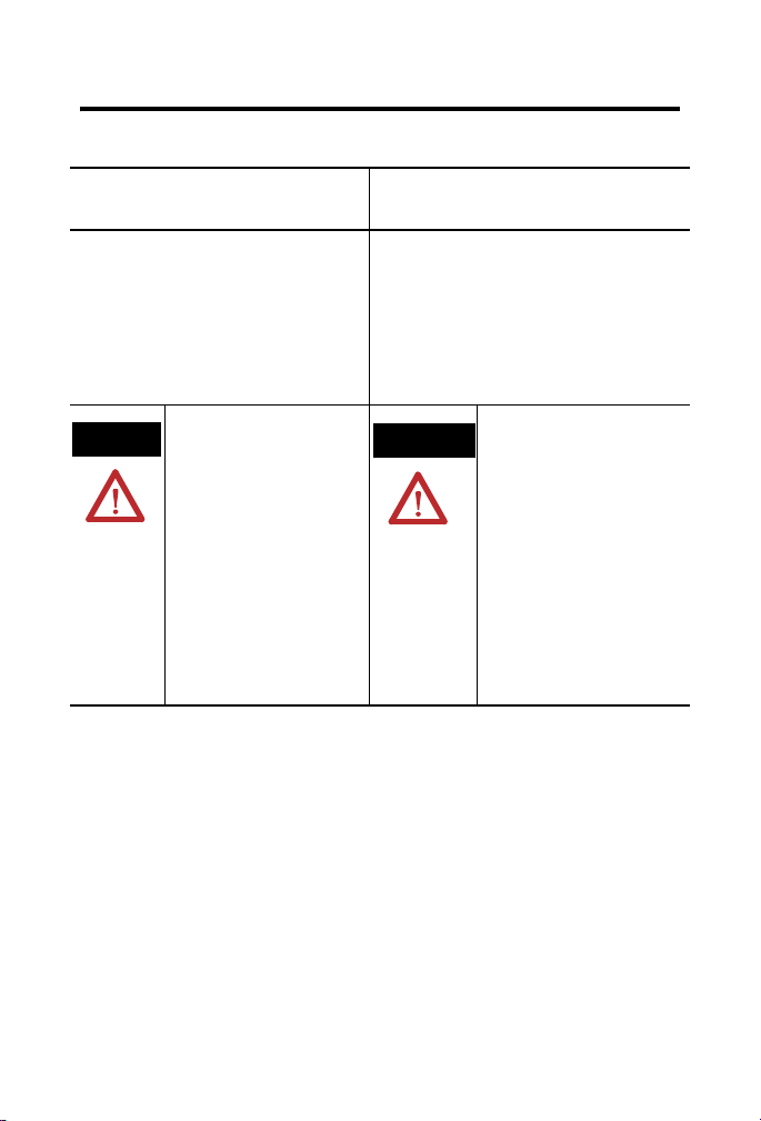
North American Hazardous Location Approval
The following information applies when
operating this equipment in hazardous
locations:
Products marked “CL I, DIV 2, GP A, B, C, D” are suitable
for use in Class I Division 2 Groups A, B, C, D, hazardous
locations and nonhazardous locations only. Each product is
supplied with markings on the rating nameplate indicating
the hazardous location temperature code. When
combining products within a system, the most adverse
temperature code (lowest “T” number) may be used to
help determine the overall temperature code of the
system. Combinations of equipment in your system are
subject to investigation by the local Authority Having
Jurisdiction at the time of installation.
EXPLOSION HAZARD -
WARNING
• Do not disconnect equipment unless
power has been removed or the area
is known to be nonhazardous.
• Do not disconnect connections to
this equipment unless power has
been removed or the area is known
to be nonhazardous. Secure any
external connections that mate to
this equipment by using screws,
sliding latches, threaded
connectors, or other means provided
with this product.
• Substitution of components may
impair suitability for Class I, Division
2.
• If this product contains batteries,
they must only be changed in an
area known to be nonhazardous.
Informations sur l’utilisation de cet équipement
en environnements dangereux:
Les produits marqués “CL I, DIV 2, GP A, B, C, D” ne
conviennent qu’à une utilisation en environnements de Classe I
Division 2 Groupes A, B, C, D dangereux et non dangereux.
Chaque produit est livré avec des marquages sur sa plaque
d’identification qui indiquent le code de température pour les
environnements dangereux. Lorsque plusieurs produits sont
combinés dans un système, le code de température le plus
défavorable (code de température le plus faible) peut être
utilisé pour déterminer le code de température global du
système. Les combinaisons d’équipements dans le système
sont sujettes à inspection par les autorités locales qualifiées
au moment de l’installation.
AVERTISSEMENT
RISQUE D’EXPLOSION –
• Couper le courant ou s’assurer que
l’environnement est classé non
dangereux avant de débrancher
l'équipement.
• Couper le courant ou s'assurer que
l’environnement est classé non
dangereux avant de débrancher les
connecteurs. Fixer tous les
connecteurs externes reliés à cet
équipement à l'aide de vis, loquets
coulissants, connecteurs filetés ou
autres moyens fournis avec ce
produit.
• La substitution de composants peut
rendre cet équipement inadapté à une
utilisation en environnement de
Classe 1, Division 2.
• S’assurer que l’environnement est
classé non dangereux avant de
changer les piles.
Publication
1734-IN585C-EN-E - December 2005
Page 6
6 POINT I/O Protected Sink Output Module
About the Module
Use this series C module with the following:
• ControlNet adapters
with RSLogix 5000 software, version 11 or higher
• DeviceNet adapters
• EtherNet/IP adapters
with RSLogix 5000 software, version 11 or higher
• PROFIBUS adapters
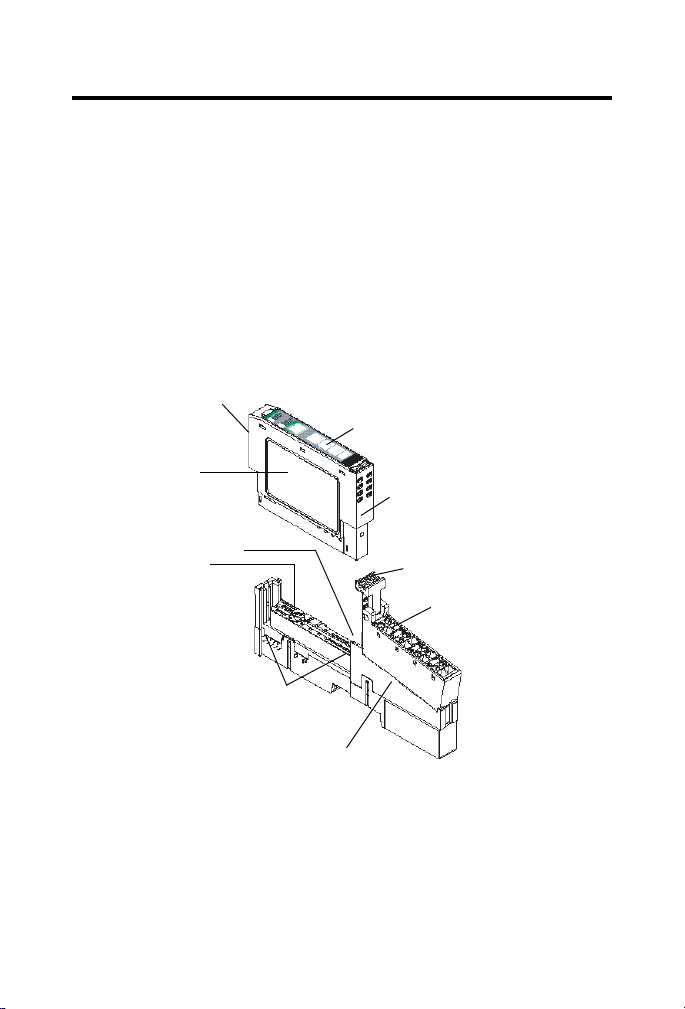
Refer to the figure to identify external features of the module.
Module Locking
Mechanism
Slide-in Writable Label
Module Wiring
Diagram
DIN Rail Locking
Screw (orange)
Mechanical
Keying
(orange)
Insertable I/O
Module
RTB Removal Handle
Removable Terminal
Block (RTB)
Publication
Interlocking Side
Pieces
Mounting Base
1734-IN585C-EN-E - December 2005
31830GM
Page 7
POINT I/O Protected Sink Output Module 7
N
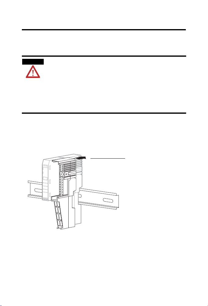
Install the Mounting Base
To install the mounting base on the DIN rail, proceed as follows.
ATTENTIO
POINT I/O is grounded through the DIN rail to chassis
ground. Use zinc-plated yellow-chromate steel DIN rail to
assure proper grounding. The use of other DIN rail
material (for example, aluminum and plastic) that can
corrode, oxidize, or are poor conductors, can result in
improper or intermittent grounding.
Secure DIN rail to mounting surface approximately every
200 mm (7.8 in.).
1. Position the mounting base vertically above the installed units
(adapter, power supply, or existing module).
2. Slide the mounting base down, allowing the interlocking side
pieces to engage the adjacent module or adapter.
Slide the mounting base to
allow the interlocking side
pieces to engage the
adjacent module or
adapter.
31586
3. Press firmly to seat the mounting base on the DIN rail.
The mounting base snaps into place.
Publication
1734-IN585C-EN-E - December 2005
Page 8

8 POINT I/O Protected Sink Output Module
N
Install the Module
ATTENTIO
When you insert or remove the module while backplane
power is on, an electrical arc can occur. This could cause
an explosion in hazardous location installations.
Be sure that power is removed or the area is
nonhazardous before proceeding. Repeated electrical
arcing causes excessive wear to contacts on both the
module and its mating connector. Worn contacts may
create electrical resistance that can affect module
operation.
Install the module before or after base installation. Be sure that you
complete the following.
• Correctly key the mounting base before installing the module
into the mounting base.
• Position the mounting base locking screw horizontal
referenced to the base.
Publication
1734-IN585C-EN-E - December 2005
Page 9
POINT I/O Protected Sink Output Module 9
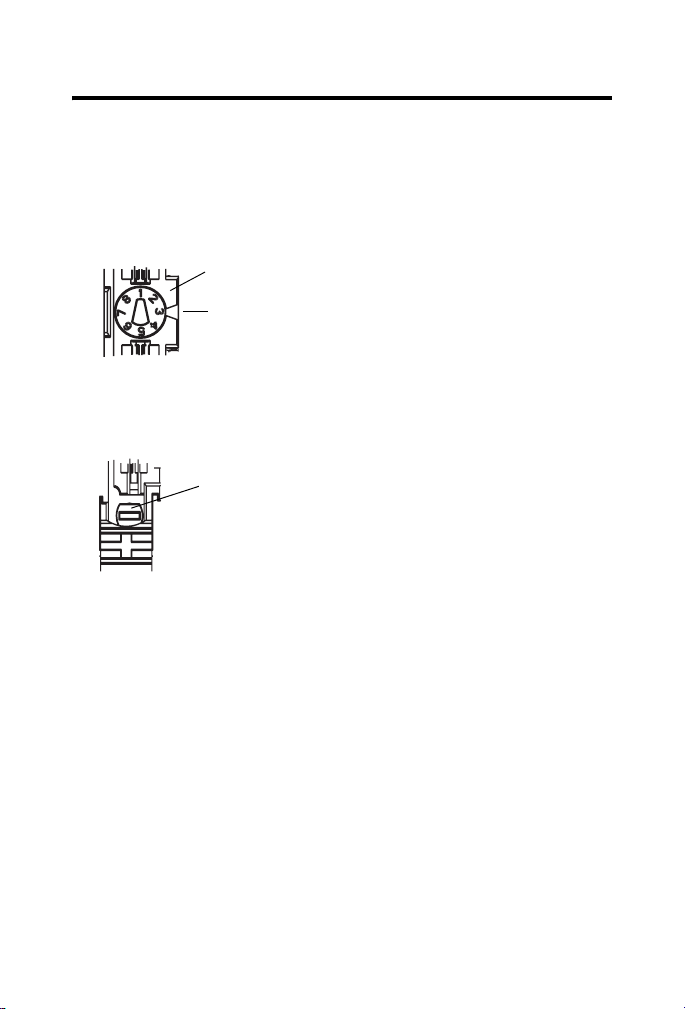
To install the module on the DIN rail, proceed as follows.
1. Use a bladed screwdriver to rotate the keyswitch on the
mounting base clockwise until the number required for the
type of module being installed aligns with the notch in the
base.
Turn the keyswitch to align the number with the notch.
Notch
(position 3 shown)
44009
2. Be sure the DIN rail locking screw is in the horizontal
position.
Make sure the DIN rail
locking screw is in the
horizontal position.
44010
If you unlock the locking mechanism, you cannot insert the
module.
Publication
1734-IN585C-EN-E - December 2005
Page 10
10 POINT I/O Protected Sink Output Module
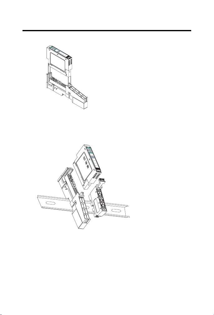
3. Insert the module straight down into the mounting base.
Module
Status
Network
Status
NODE:
24VDC
Source
Output
0
1
2
3
1734
OB4E
44012
4. Press to secure.
The module locks into place.
M
odule
Status
N
e
tw
o
rk
S
ta
tu
s
N
O
D
E
:
2
4
V
D
C
S
o
u
rc
e
O
u
tp
u
t
0
1
2
3
1
7
3
4
O
B
4
E
Publication
30880
1734-IN585C-EN-E - December 2005
Page 11

POINT I/O Protected Sink Output Module 11
Install the Removable Terminal Block (RTB)
A removable terminal block comes with your wiring base. To
remove, pull up on the RTB handle. Remove or replace the
mounting base without removing any of the wiring.
WARNING
When you connect or disconnect the removable terminal
block (RTB) with field-side power applied, an electrical
arc can occur. This could cau se an explosion in hazardous
location installations.
Be sure that power is removed or the area is
nonhazardous before proceeding.
1. Insert the end opposite the handle into the base unit, noting
that this end has a curved section that engages with the wiring
base.
2. Rotate the terminal block into the wiring base until it locks
itself in place.
3. If you installed an I/O module, snap the RTB handle into
place on the module.
44011
Publication
1734-IN585C-EN-E - December 2005
Page 12
12 POINT I/O Protected Sink Output Module
Remove a Mounting Base
To remove a module from the DIN rail, remove any installed mo dule
and the module installed in the base to the right. Remove the
removable terminal block, if wired.
1. Unlach the RTB handle on the I/O module.
2. Pull on the RTB handle to remove the removable terminal
block.
WARNING
3. Press on the module lock on the top of the module.
When you connect or disconnect the removable terminal
block (RTB) with field-side power applied, an electrical
arc can occur. This could cau se an explosion in hazardous
location installations.
Be sure that power is removed or the area is
nonhazardous before proceeding.
Publication
1734-IN585C-EN-E - December 2005
Page 13
POINT I/O Protected Sink Output Module 13
N
4. Pull on the I/O module to remove from the base.
ATTENTIO
When you insert or remove the module while backplane
power is on, an electrical arc can occur. This could cause
an explosion in hazardous location installations.
Be sure that power is removed or the area is
nonhazardous before proceeding. Repeated electrical
arcing causes excessive wear to contacts on both the
module and its mating connector. Worn contacts may
create electrical resistance that can affect module
operation.
5. Repeat steps 1, 2, 3, and 4 for the module to the right.
6. Use a small-bladed screwdriver to rotate the orange base
locking screw to a vertical position.
This releases the locking mechanism on the mounting base.
7. Lift straight up to remove the mounting base.
Publication
1734-IN585C-EN-E - December 2005
Page 14

14 POINT I/O Protected Sink Output Module
Wire the Module
Refer to the figures to wire the module.
WARNING
If you connect or disconnect wiring while the field-side
power is on, an electrical arc can occur. This could cause
an explosion in hazardous location installations. Be sure
that power is removed or the area is nonhazardous before
proceeding.
IMPORTANT
To comply with the CE Low V oltage Directive (L VD), I/O
must be powered from a source compliant with the
following: Safety Extra Low Voltage (SELV) or Protected
Extra Low Voltage (PELV).
1734-OV2E 1734-OV4E
Module Status
Module
Status
Network
Status
Network Status
NODE:
24VDC
Status of Output 0
Sink
Output
0
Status of Output 1
1
Status of Output 2
Status of Output 3
1734
OV2E
Output 0
N/C
C
V
Output 1
N/C
C
V
Output 0
Output 2
V
V
Module
Status
Network
Status
NODE:
24VDC
Status of Output 0 & 4
Sink
Output
0
Status of Output 1 & 5
1
Status of Output 2 & 6
2
2
Status of Output 3 & 7
3
1734
OV4E
Output 1
Output 3
V
V
Output 0
Output 2
Output 4
Output 6
1734-OV8E
Module
Status
Network
Status
NODE:
24VDC
Sink
Output
0
1
2
3
1734
OV8E
4
5
6
7
Output 1
Output 3
Output 5
Output 7
C = Common
V = Supply
Publication
1734-IN585C-EN-E - December 2005
4202942028
42030
Page 15

POINT I/O Protected Sink Output Module 15
1734-OV2E
Load
V = 12/24V dc, C = Common
Field power is supplied from internal power bus.
0
2
4
6
Out 0
N/C
C
V
N/C
Output
Terminal
Channel 0 0 6 4
Channel 1 1 7 5
Module power is supplied from the inter nal p owe r bus .
1
Out 1
3
5
C
7
V
Power Common
Load
42014
Terminal
Publication
1734-IN585C-EN-E - December 2005
Page 16

16 POINT I/O Protected Sink Output Module
1734-OV4E
Load
V = 12/24V dc, C = Common
Field power is supplied from internal power bus.
Load
0
Out 0 Out 1
2
45
V
6
V
Output
Terminal
Channel 0 0 6
Channel 1 1 7
Channel 2 2 4
Channel 3 3 5
Module power is supplied from the internal power bus.
1
3
Out 3Out 2
V
7
V
Power Common
Load
Terminal
Load
42015
Publication
1734-IN585C-EN-E - December 2005
Page 17

POINT I/O Protected Sink Output Module 17
C
u
p
1734-OV8E
ommon must be daisychained from a 1734 adapter, 1734-FPD, 1734-EP24DC, or from a
ser-supplied external terminal block. The 24V dc power to the module is supplied by the internal
ower bus and comes from the same 1734 adapter, 1734-FPD, or 1734-EP24DC as common.
V
Channel
Number
Load
Load
Load
Load
Output
Terminal
0
Out 0
2
Out 2
4
Out 4
6
Out 6
Common Terminal Power
Channel 0 0 Common is daisychained
Channel 1 1
Channel 2 2
Channel 3 3
from either a 1734 adapter,
1734-FPD, 1734-EP24DC, or
from a user-supplied
external terminal block.
Out 1
Out 3
Out 5
Out 7
1
3
5
7
Load
Load
Load
Load
The 24V dc power for the
module is supplied by the
internal power bus and
originates from the same
adapter, 1734-FPD, or
1734-EP24DC as common.
Channel 4 4
Channel 5 5
Channel 6 6
Channel 7 7
Module power is supplied from the internal power bus.
V
42015
Publication
1734-IN585C-EN-E - December 2005
Page 18

18 POINT I/O Protected Sink Output Module
Example of Wiring for the 1734-OV8E Output Module
Module
Module
Status
Status
Network
Network
Status
DeviceNet
DeviceNet
24V dc Return
24V dc
Notes:
The 1734-OB8E maximum load is
1A maximum per channel, and 3A
total per module.
Terminal Block with Bus Connector Strip
System
Power
Power
Status
1734-
1734-
IV8
OV8E
0
4
0
1
5
1
2
6
2
3
7
3
1734
1734
OB8E
IB8
Terminal Block with
4
5
6
7
Load
Bus connector strip
The 1734-OV8E maximum load is
1 A min per channel, and
3 A total per module.
Load
Load
Load
Load
Load
Load
44023
Load
Configure the Module
POINT I/O modules send (consume) and receive (produce) I/O
messages. You map these messages into the processor memory. This
POINT I/O output module produces 1 byte of input data (scanner Rx)
(status). It consumes 1 byte of I/O data (scanner Tx).
Publication
1734-IN585C-EN-E - December 2005
Page 19

POINT I/O Protected Sink Output Module 19
Default Data Map for the 1734-OV2E Output Module
Message size: 1 Byte
76543 2 1 0
Produces
(scanner Rx)
Where: 0 = no error, 1 = error
Message size: 1 Byte
76543 2 1 0
Consumes
(scanner Tx)
Where: 0 = Off, 1 = On
Not used Ch1 Ch0 Channel status
Not used Ch1 Ch0 Channel state
Default Data Map for the 1734-OV4E Output Module
Message size: 1 Byte
76543 2 1 0
Produces
(scanner Rx)
Where: 0 = no error, 1 = error
Not used Ch3 Ch2 Ch1 Ch0 Channel
status
Message size: 1 Byte
76543 2 1 0
Consumes
(scanner Tx)
Where: 0 = Off, 1 = On
Not used Ch3 Ch2 Ch1 Ch0 Channel
Publication
1734-IN585C-EN-E - December 2005
state
Page 20

20 POINT I/O Protected Sink Output Module
Default Data Map for the 1734-OV8E Output Module
Message size: 1 Byte
76543210
Produces
(scanner Rx)
Where: 0 = no error, 1 = error
Message size: 1 Byte
Consumes
(scanner Tx)
Where: 0 = no error, 1 = error
Ch7 Ch6 Ch5 Ch4 Ch3 Ch2 Ch1 Ch0 Channel
76543210
Ch7 Ch6 Ch5 Ch4 Ch3 Ch2 Ch1 Ch0 Channel
status
state
Publication
1734-IN585C-EN-E - December 2005
Page 21

Troubleshoot the Module
1734-OV2E 1734-OV4E
POINT I/O Protected Sink Output Module 21
1734-OV8E
Module
Module Status
Status
Network
Status
NODE:
Network Status
24VDC
Sink
Output
0
1
Status of Output 0
Status of Output 1
1734
Status of Output 2
OV2E
Status of Output 3
Module
Status
Network
Status
NODE:
24VDC
Sink
Output
0
1
Status of Output 0 & 4
2
2
Status of Output 1 & 5
3
1734
Status of Output 2 & 6
OV4E
Status of Output 3 & 7
Module
Status
Network
Status
NODE:
24VDC
Sink
Output
0
4
5
1
6
2
7
3
1734
OV8E
Indication Probable Cause Recommended Action
Module Status
Off No power applied to device. Apply power applied to device.
Solid Green Device is operating normally. Device is operating normally.
Flashing Green Device needs commissioning
Configure device properly.
due to configuration missing,
incomplete, or incorrect.
Flashing Red Recoverable fault is present. 1. Cycle power.
2. Configure device properly if
needed.
3. If condition persists, replace
device.
Solid Red Unrecoverable fault may
Replace device.
require device replacement.
Flashing Red/Green Device is in self-test. None
Publication
1734-IN585C-EN-E - December 2005
Page 22

22 POINT I/O Protected Sink Output Module
Indication Probable Cause Recommended Action
Network Status
Off Device is not online.
- Device has not completed
dup_MAC_id test.
- Device not powered - check module
status indicator.
Flashing Green Device is online but has no
connections in the established state.
Solid Green Device is online and has connections
in the established state.
Flashing Red One or more I/O connections are in
timed-out state.
Solid Red Critical link failure - failed
communication device is present.
Device detected error that prevents it
communicating on the network.
Flashing Red/Green Communication faulted device - the
device has detected a network access
error and is in communication faulted
state. Device has received and
accepted an Identify Communication
Faulted Request - long protocol
message.
I/O Status
Off All outputs are inactive. None
Solid Yellow One or more outputs are active and
under control.
Solid Red Overload, short circuit, or
overtemperature detected (On-State
only).
Apply power to the device,
wait for MAC-id to
complete, and correct, if
needed.
None - device is in Idle or
Program mode.
None
Check for I/O module
failure, and correct, as
needed.
1. Reinstall adapter and
terminal base, if
improperly installed.
2. Correct duplicate
MAC_id, if needed.
Verify that adapter is
properly installed, and
reinstall, as needed.
None
Remove overload, short
circuit, or overtemperature
condition.
Publication
1734-IN585C-EN-E - December 2005
Page 23

POINT I/O Protected Sink Output Module 23
Specifications
1734-OV2E/C, 1734-OV4E/C, and 1734-OV8E/C
Protected Sink Output Modules
Specification Value
Number of Outputs 1734-OV2E - 2 (1 group of 2) non-isolated, sinking
ON-State Voltage Range 10V dc min
ON-State Voltage Drop 0.7V dc max (at 28.8V dc, 55 °C, full load condition)
ON-State Current 1.0 mA min per channel
OFF-State Voltage 28.8V dc max
OFF-State Leakage 0.5 mA max
1734-OV4E - 4 (1 group of 4) non-isolated, sinking
1734-OV8E - 8 (1 group of 8) non-isolated, sinking
24V dc nom
28.8V dc max
1.0 A max per channel (electronically protected)
Output Signal Delay
OFF to ON
ON to OFF
Output Current Rating 1734-OV2E - 1.0 A per output, 2.0 A max per module
Surge Current 2 A for 10 ms, repeatable every 3 s
Indicators (field side
indication, logic driven)
Keyswitch Position 1
(1)
0.1 ms max
0.1 ms max
1734-OV4E and 1734-OV8E - 1.0 A per output, not to exceed
3.0 A max per module
1734-OV2E
2 yellow output status
2 red output fault
2 green/red module/network status
1734-OV4E
4 yellow output status
4 red output fault
2 green/red module/network status
1734-OV8E
8 yellow output status
8 red output fault
2 green/red module/network status
Publication
1734-IN585C-EN-E - December 2005
Page 24

24 POINT I/O Protected Sink Output Module
1734-OV2E/C, 1734-OV4E/C, and 1734-OV8E/C
Protected Sink Output Modules
Specification Value
Module Location 1734-TB or 1734-TBS wiring base assembly
POINTBus Current 75 mA max @ 5V dc
Power Dissipation 1734-OV2E - 0.8 W max @ 28.8V dc
Thermal Dissipation 1734-OV2E - 2.7 BTU/hr max @ 28.8V dc
Isolation
(continuous-voltage rating)
External dc Power
Supply Voltage
Voltage Range
Supply Current
Dimensions HxWxD,
Approx.
Weight 1734-OV2E - 32.60 g (1.15 oz)
Terminal Base Screw Torque 7 lb-in (0.6 Nm) max
Wire Size
Wiring Category
(2)
1734-OV4E - 1.2 W max @ 28.8V dc
1734-OV8E - 2.0 W max @ 28.8V dc
1734-OV4E - 4.1 BTU/hr max @ 28.8V dc
1734-OV8E - 6.8 BTU/hr max @ 28.8V dc
240V, Basic Insulation Type, tested at 2550V dc for
60 seconds, output to system
24V dc nom
10…28.8V dc
1734-OV2E - 8 mA
1734-OV4E - 16 mA
1734-OV8E - 32 mA
56.0 x 12.0 x 75.5 mm
(2.21 x 0.47 x 2.97 in.)
1734-OV4E - 33.17 g (1.17 oz)
1734-OV8E - 35.4 g (1.25 oz)
22…14 AWG (0.25…2.5 mm
2
)
solid or stranded copper wire rated @ 75
1.2 mm (3/64 in.) insulation max
1 - on signal ports
o
C or greater
Publication
1734-IN585C-EN-E - December 2005
Page 25

POINT I/O Protected Sink Output Module 25
1734-OV2E/C, 1734-OV4E/C, and 1734-OV8E/C
Protected Sink Output Modules
Specification Value
Pilot Duty Rating 24V dc 1.0 A
North American
Temperature Code
Field Wiring Terminations 1734-OV2E
(1)
Off/on delay is time from a valid output on signal to output energization. On/off delay is time from a
valid output off signal to output deenergization.
(2)
Use this conductor category information for planning conductor routing as described in Industrial
Automation Wiring and Grounding Guidelines, publication 1770-4.1.
T4
0 - Output 0 1 - Output 1
2 - Output 0 3 - Output 1
4 - Common 5 - Common
6 - Supply 7- Supply
1734-OV4E
0 - Output 0 1 - Output 1
2 - Output 2 3 - Output 3
4 - Supply 5 - Supply
6 - Supply 7 - Supply
1734-OV8E
0 - Output 0 1 - Output 1
2 - Output 2 3 - Output 3
4 - Output 4 5 - Output 5
6 - Output 6 7 - Output 7
Publication
1734-IN585C-EN-E - December 2005
Page 26

26 POINT I/O Protected Sink Output Module
Environmental Specifications
Specification Value
Operational
Temperature
Storage Temperature IEC60068-2-1 (Test Ab, Unpackaged Non-operating Cold)
Relative Humidity IEC60068-2-30
Vibration IEC 60068-2-6 (Test Fc, Operating)
Shock Operating IEC60068-2-27 (Test Ea, Unpackaged Shock) 30 g
Shock Non-operating IEC60068-2-27 (Test Ea, Unpackaged Shock) 50 g
Emissions CISPR 11: Group 1, Class A
ESD Immunity IEC6100-4-2
Radiated RF Immunity IEC 61000-4-3
EFT/B Immunity IEC 61000-4-4
IEC 60068-2-1 (Test Ad, Operating Cold),
IEC 60068-2-2 (Test Bd, Operating Dry Heat),
IEC 60068-2-14 (Test Nb, Operating Thermal Shock)
-20...55 °C (-4...131 °F)
IEC60068-2-2 (Test Bb, Unpackaged Non-operating Dry Heat)
IEC60068-2-14 (Test Na, Unpackaged Non-operating Thermal
Shock)
-40...85 °C (-40...185 °F)
(Test Db, Unpackaged Damp Heat)
5...95% noncondensing
5 g @ 10...500 Hz
6 kV contact discharges
8 kV air discharges
10V/m with 1 KHz sine-wave 80% AM from 30...2000 MHz
10V/m with 200 Hz 50% Pulse 100% AM at 900 MHz
10V/m with 200 Hz 50% Pulse 100% AM at 1890 MHz
1V/m with 1 kHz sine-wave 80% AM from 2000...2700 MHz
+
4 kV at 5 kHz on signal ports
Publication
1734-IN585C-EN-E - December 2005
Page 27

Environmental Specifications
POINT I/O Protected Sink Output Module 27
Surge Transient
Immunity
IEC 61000-4-5
+
1 kV line-line (DM) and +2 kV line-earth (CM) on signal ports
Conducted RF Immunity IEC61000-4-6
10V rms with 1 kHz sine-wave 80% AM from 150 kHz...80 MHz
Enclosure Type Rating None (open-style)
Certification
Certification Value
Certification
(1)
(when product is
marked)
(1)
See the Product Certification link at www.ab.com for Declarations of Conformity, Certificates, and
other certification details.
c-UL-us UL Listed Industrial Control Equipment, certified for
U.S. and Canada. See UL File E65584.
c-UL-us UL Listed for Class I, Division 2, Group A,B,C,D
Hazardous Locations, certified for U.S. and Canada.
See UL File E194810.
CE European Union 89/336/EEC EMC Directive,
compliant with:
EN 50082-2; Industrial Immunity
EN 61326; Meas./Control/Lab.,Industrial Requirements
EN 61000-6-2; Industrial Immunity
EN 61000-6-4; Industrial Emissions
EN 61131-2; Programmable Controllers
(Clause 8, Zone A and B)
C-Tick Australian Radiocommunications Act,
compliant with:
AS/NZS CISPR11; Industrial Emissions
POINT I/O and POINTBus are trademarks of Rockwell Automation, Inc.
Trademarks not belonging to Rockwell Automation are property of their respective companies.
Publication
1734-IN585C-EN-E - December 2005
Page 28
Rockwell Automation Support
Rockwell Automation provides technical info rmation on the web to assist you
in using its products. At http://support .rockwell aut omation .com, y ou can find
technical manuals, a knowledge base of FAQs, technical and application
notes, sample code and links to software service packs, and a MySupport
feature that you can customize to make the best use of these tools.
For an additional level of technical phone support for installation,
configuration and troubleshooting, we offer TechConnect Support programs.
For more information, contact your local distributor or Rockwell Automation
representative, or visit http://support.rockwellautomation.com.
Installation Assistance
If you experience a problem with a hardware module wit hin the first 24 hours
of installation, please review the information that's contained in this manual.
You can also contact a special Customer Support number for initial help in
getting your module up and running:
United States 1.440.646.3223 Monday – Friday, 8am – 5pm EST
Outside United States Please contact your local Rockwell Automation representative for any
New Product Satisfaction Return
Rockwell tests all of its products to ensure that they are ful ly operational when
shipped from the manufacturing facility. However, if your product is not
functioning and needs to be returned:
United States Contact your distributor. You must provide a Customer Support case number
Outside United States Please contact your local Rockwell Automation representative for return
technical support issues.
(see phone number above to obtain one) to your distributor in order to
complete the return process.
procedure.
Publication 1734-IN585C-EN-E - December 2005 PN 957974-57
Supersedes Publication 1734-IN585B-EN-P - March 2002 Copyright © 2005 Rockwell Automation, Inc. All rights reserved. Printed in the U.S.A.
 Loading...