

Page 1

POINT I/O Thermocouple and RTD
Modules
Catalog Numbers 1734-IR2, 1734-IR2E and 1734-IT2I
User Manual
Page 2
2
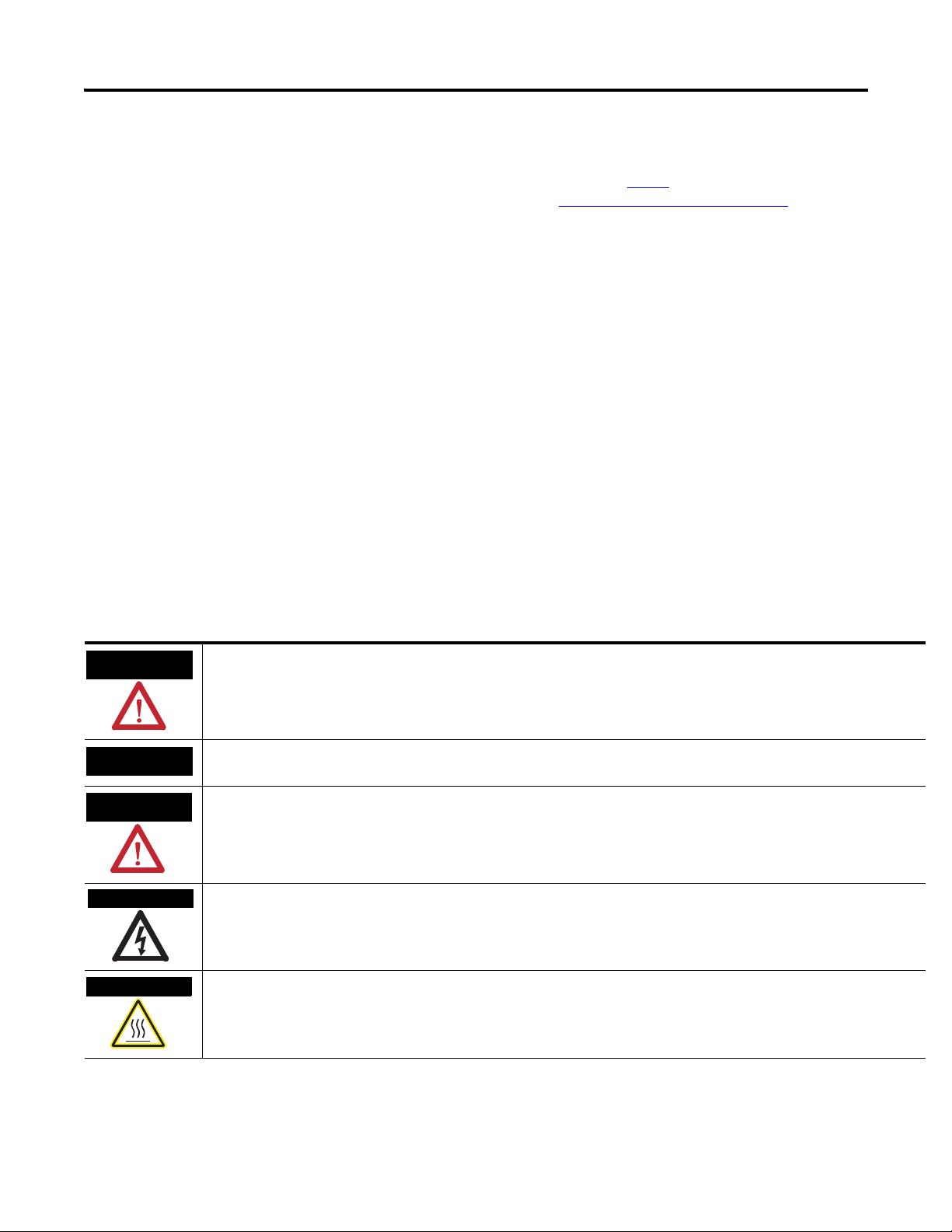
WARNING
IMPORTANT
ATTENTION
SHOCK HAZARD
BURN HAZARD
Important User Information
Solid state equipment has operational characteristics differing from those of
electromechanical equipment. Safety Guidelines for the Application, Installation and
Maintenance of Solid State Controls (publication SGI-1.1
Automation sales office or online at http://literature.rockwellautomation.com
available from your local Rockwell
) describes
some important differences between solid state equipment and hard-wired
electromechanical devices. Because of this difference, and also because of the wide variety
of uses for solid state equipment, all persons responsible for applying this equipment must
satisfy themselves that each intended application of this equipment is acceptable.
In no event will Rockwell Automation, Inc. be responsible or liable for indirect or
consequential damages resulting from the use or application of this equipment.
The examples and diagrams in this manual are included solely for illustrative purposes.
Because of the many variables and requirements associated with any particular installation,
Rockwell Automation, Inc. cannot assume responsibility or liability for actual use based on
the examples and diagrams.
No patent liability is assumed by Rockwell Automation, Inc. with respect to use of
information, circuits, equipment, or software described in this manual.
Reproduction of the contents of this manual, in whole or in part, without written permission
of Rockwell Automation, Inc., is prohibited.
Throughout this manual, when necessary, we use notes to make you aware of safety
considerations.
Identifies information about practices or circumstances that can cause an explosion in a hazardous environment, which may
lead to personal injury or death, property damage, or economic loss.
Identifies information that is critical for successful application and understanding of the product.
Identifies information about practices or circumstances that can lead to: personal injury or death, property damage, or
economic loss. Attentions help you identify a hazard, avoid a hazard, and recognize the consequence.
Labels may be on or inside the equipment, such as a drive or motor, to alert people that dangerous voltage may be present.
Labels may be on or inside the equipment, such as a drive or motor, to alert people that surfaces may reach dangerous
temperatures.
Allen-Bradley, Rockwell Automation, POINT I/O, RSLinx, RSLogix 5000, and TechConnect are trademarks of Rockwell Automation, Inc.
Trademarks not belonging to Rockwell Automation are property of their respective companies.
Publication 1734-UM004F-EN-E - December 2012
Page 3

Summary of Changes
About POINT I/O Modules
Table of Contents
Important User Information . . . . . . . . . . . . . . . . . . . . . . . . . . . . . . . . . . 2
New and Revised Information . . . . . . . . . . . . . . . . . . . . . . . . . . . . . 7
Change Bars . . . . . . . . . . . . . . . . . . . . . . . . . . . . . . . . . . . . . . . . . . . . 7
Preface
Who Should Use this Manual . . . . . . . . . . . . . . . . . . . . . . . . . . . . . . . . . 9
Purpose of this Manual . . . . . . . . . . . . . . . . . . . . . . . . . . . . . . . . . . . . . . 9
Related Documentation. . . . . . . . . . . . . . . . . . . . . . . . . . . . . . . . . . . 9
Common Techniques Used in this Manual. . . . . . . . . . . . . . . . . . . . . . 10
Chapter 1
Overview. . . . . . . . . . . . . . . . . . . . . . . . . . . . . . . . . . . . . . . . . . . . . . . . . 11
Module Features. . . . . . . . . . . . . . . . . . . . . . . . . . . . . . . . . . . . . . . . . . . 11
Selecting a Module Input Type . . . . . . . . . . . . . . . . . . . . . . . . . . . . . . . 12
Communicating with Your Module. . . . . . . . . . . . . . . . . . . . . . . . . . . . 12
Default Data Map for the Thermocouple Input Module
(catalog number 1734-IT2I) . . . . . . . . . . . . . . . . . . . . . . . . . . . . . . 13
Default Data Map for the RTD Input Module
(catalog numbers 1734-IR2, and 1734-IR2E). . . . . . . . . . . . . . . . . 13
Data Format (1734-IT2I, 1734-IR2, and 1734-IR2E modules) . . 14
Use Module Alarms . . . . . . . . . . . . . . . . . . . . . . . . . . . . . . . . . . . . . . . . 15
Overrange Alarm (1734-IT2I, 1734-IR2, and
1734-IR2E modules) . . . . . . . . . . . . . . . . . . . . . . . . . . . . . . . . . . . . 15
Underrange Alarm (1734-IT2I, 1734-IR2, and
1734-IR2E modules) . . . . . . . . . . . . . . . . . . . . . . . . . . . . . . . . . . . . 15
Level Alarms (1734-IT2I, 1734-IR2, and
1734-IR2E modules) . . . . . . . . . . . . . . . . . . . . . . . . . . . . . . . . . . . . 15
Open-wire Alarm (1734-IT2I, 1734-IR2, and
1734-IR2E modules) . . . . . . . . . . . . . . . . . . . . . . . . . . . . . . . . . . . . 16
Cold Junction Compensation (1734-IT2I module) . . . . . . . . . . . . . . . 16
Chapter Summary. . . . . . . . . . . . . . . . . . . . . . . . . . . . . . . . . . . . . . . . . . 16
Chapter 2
Install the Module
Overview. . . . . . . . . . . . . . . . . . . . . . . . . . . . . . . . . . . . . . . . . . . . . . . . . 17
Preventing Electrostatic Discharge. . . . . . . . . . . . . . . . . . . . . . . . . 17
Environment and Enclosure . . . . . . . . . . . . . . . . . . . . . . . . . . . . . . 18
Install the Mounting Base . . . . . . . . . . . . . . . . . . . . . . . . . . . . . . . . . . . 18
Install an I/O Module . . . . . . . . . . . . . . . . . . . . . . . . . . . . . . . . . . . . . . 20
Install the Removable Terminal Block . . . . . . . . . . . . . . . . . . . . . . . . . 21
Remove a Mounting Base . . . . . . . . . . . . . . . . . . . . . . . . . . . . . . . . . . . 22
Wire the Modules . . . . . . . . . . . . . . . . . . . . . . . . . . . . . . . . . . . . . . . . . . 23
Chapter Summary. . . . . . . . . . . . . . . . . . . . . . . . . . . . . . . . . . . . . . . . . . 24
Chapter 3
Configure Your Module
iii Publication 1734-UM004F-EN-E - December 2012
Overview. . . . . . . . . . . . . . . . . . . . . . . . . . . . . . . . . . . . . . . . . . . . . . . . . 25
Configuration Overview . . . . . . . . . . . . . . . . . . . . . . . . . . . . . . . . . . . . 25
Commissioning a Node . . . . . . . . . . . . . . . . . . . . . . . . . . . . . . . . . . . . . 25
Page 4

iv Table of Contents
Using the RSNetWorx Commissioning Tool. . . . . . . . . . . . . . . . . 26
Use Sequential Auto Addressing. . . . . . . . . . . . . . . . . . . . . . . . . . . 27
Use Third Party Configuration Software . . . . . . . . . . . . . . . . . . . . 27
Add the Adapter to Your Network. . . . . . . . . . . . . . . . . . . . . . . . . . . . 27
Add I/O Modules to Your Network POINTBus. . . . . . . . . . . . . 28
Set the Thermocouple Input Module Parameters Using RSNetWorx 30
Configure Your Thermocouple Input Module. . . . . . . . . . . . . . . . . . . 32
Basic Set-up Parameters . . . . . . . . . . . . . . . . . . . . . . . . . . . . . . . . . 32
Advanced Setup Parameters . . . . . . . . . . . . . . . . . . . . . . . . . . . . . . 33
Basic Setup . . . . . . . . . . . . . . . . . . . . . . . . . . . . . . . . . . . . . . . . . . . 35
Advanced Setup. . . . . . . . . . . . . . . . . . . . . . . . . . . . . . . . . . . . . . . . 36
Set the RTD Input Module Parameters Using RSNetWorx . . . . . . . . 37
Configure Your RTD Input Module . . . . . . . . . . . . . . . . . . . . . . . . . . 39
Basic Setup Parameters . . . . . . . . . . . . . . . . . . . . . . . . . . . . . . . . . . 39
Advanced Setup Parameters . . . . . . . . . . . . . . . . . . . . . . . . . . . . . . 40
Basic Setup. . . . . . . . . . . . . . . . . . . . . . . . . . . . . . . . . . . . . . . . . . . . 42
Advanced Setup. . . . . . . . . . . . . . . . . . . . . . . . . . . . . . . . . . . . . . . . 43
Check I/O Status and View the EDS File . . . . . . . . . . . . . . . . . . . . . . 44
1734-IT2I module . . . . . . . . . . . . . . . . . . . . . . . . . . . . . . . . . . . . . . 44
1734-IR2 and 1734-IR2E modules. . . . . . . . . . . . . . . . . . . . . . . . . 45
Chapter Summary . . . . . . . . . . . . . . . . . . . . . . . . . . . . . . . . . . . . . . . . . 46
Calibrate Your Module
Troubleshoot the Module
Configure Modules in
RSLogix 5000 Software
Chapter 4
Overview . . . . . . . . . . . . . . . . . . . . . . . . . . . . . . . . . . . . . . . . . . . . . . . . 47
When and How to Calibrate Your Module . . . . . . . . . . . . . . . . . . . . . 47
Calibration Method . . . . . . . . . . . . . . . . . . . . . . . . . . . . . . . . . . . . . . . . 47
Tools and Equipment Required to Calibrate
Your Thermocouple Module. . . . . . . . . . . . . . . . . . . . . . . . . . . . . . . . . 47
Calibrate the Thermocouple Input Module . . . . . . . . . . . . . . . . . . . . . 48
Access Calibration Parameters in RSNetWorx . . . . . . . . . . . . . . . 49
Input (mV) Calibration . . . . . . . . . . . . . . . . . . . . . . . . . . . . . . . . . . . . . 50
Cold Junction Compensation Calibration . . . . . . . . . . . . . . . . . . . 53
Tools and Equipment Required to Calibrate
Your RTD Module . . . . . . . . . . . . . . . . . . . . . . . . . . . . . . . . . . . . . . . . 56
Calibrate the RTD Input Module . . . . . . . . . . . . . . . . . . . . . . . . . . . . . 56
Chapter Summary . . . . . . . . . . . . . . . . . . . . . . . . . . . . . . . . . . . . . . . . . 60
Chapter 5
Overview . . . . . . . . . . . . . . . . . . . . . . . . . . . . . . . . . . . . . . . . . . . . . . . . 61
Interpret the Status Indicators. . . . . . . . . . . . . . . . . . . . . . . . . . . . . . . . 61
Chapter Summary . . . . . . . . . . . . . . . . . . . . . . . . . . . . . . . . . . . . . . . . . 62
Appendix A
Overview . . . . . . . . . . . . . . . . . . . . . . . . . . . . . . . . . . . . . . . . . . . . . . . . 63
Publication 1734-UM004F-EN-E - December 2012
Page 5

Calculate Absolute Accuracy and
Accuracy Drift
Index
Table of Contents v
Understanding Data, Connection, and
Communication Formats. . . . . . . . . . . . . . . . . . . . . . . . . . . . . . . . . . . . 63
Configure Your Module. . . . . . . . . . . . . . . . . . . . . . . . . . . . . . . . . . . . . 64
Use the Help Button . . . . . . . . . . . . . . . . . . . . . . . . . . . . . . . . . . . . . . . 65
Working with Dialogs . . . . . . . . . . . . . . . . . . . . . . . . . . . . . . . . . . . . . . 65
Work with Dialogs for RTD Modules . . . . . . . . . . . . . . . . . . . . . . 65
Work with Dialogs for Thermocouple Modules . . . . . . . . . . . . . . 70
Appendix B
Overview. . . . . . . . . . . . . . . . . . . . . . . . . . . . . . . . . . . . . . . . . . . . . . . . . 77
Calculate with Formulas. . . . . . . . . . . . . . . . . . . . . . . . . . . . . . . . . . . . . 77
Absolute Accuracy Formula . . . . . . . . . . . . . . . . . . . . . . . . . . . . . . 77
Accuracy Drift Formula. . . . . . . . . . . . . . . . . . . . . . . . . . . . . . . . . . 77
Publication 1734-UM004F-EN-E - December 2012
Page 6

vi Table of Contents
Notes:
Publication 1734-UM004F-EN-E - December 2012
Page 7

Summary of Changes
This publication contains new and revised information not in the last release.
New and Revised Information
See the table for a summary of the major changes in this manual.
Revised to include Chapter
New Appendix on Absolute Accuracy and Accuracy Drift calculation Appendix B
Change Bars
Change bars (as shown with this paragraph) show the areas in this manual that
differ from previous editions and indicate the addition of new or revised
information.
vii Publication 1734-UM004F-EN-E - December 2012
Page 8

viii Summary of Changes
Notes:
Publication 1734-UM004F-EN-E - December 2012
Page 9

Preface
Read this preface to familiarize yourself with the rest of the manual. It provides
information concerning:
• who should use this manual
• the purpose of this manual
• related documentation
• conventions used in this manual
Who Should Use this Manual
Purpose of this Manual
You must be able to use your selected configuration software to set up and
calibrate these modules. You must have the capability to download and use
files.
We assume you know how to do this in this manual. If you do not, refer to
your software user manuals or online help before attempting to use these
modules.
This manual describes how to install, configure and troubleshoot your
Thermocouple and Resistance Termperature Detector (RTD) modules.
For Information About See
About POINT I/O Modules Chapter 1
Install the Module Chapter 2
Configure Your Module Chapter 3
Calibrate Your Module Chapter 4
Troubleshoot the Module Chapter 5
Configure Modules in RSLogix 5000 Software Appendix A
Calculate Absolute Accuracy and Accuracy Drift Appendix B
Related Documentation
The following documents contain additional information concerning Rockwell
Automation products. To obtain a copy, contact your local
Rockwell Automation office or distributor.
Resource Description
POINT I/O RTD and Thermocouple Input Module
Installation Instructions, publication 1734-IN011
Analog Input Modules Installation Instructions,
publication 1734-IN024
ix Publication 1734-UM004F-EN-E - December 2012
Information about specification and safety approval concerning 1734-IT2I,
1734-IR2, and 1734-IR2E modules.
Information about how to install the 1734-IE2C, Series C, POINT I/O Current
Input Analog Module, 1734-IE2V, Series C, POINT I/O Voltage Input Analog
Module, and POINT I/O 2 Current and 2 Voltage Input Analog Module.
Page 10
x
Resource Description
Analog Output Modules Installation Instructions,
publication 1734-IN002
Cold Junction Wiring Base Assembly Installation
Instruction, publication 1734-IN583
DeviceNet Communication Interface Installation
Instructions, publication 1734-IN057
Expansion Power Supply Installation Instructions,
publication 1734-IN058
Field Potential Distributor Installation Instructions,
publication 1734-IN059
POINT I/O Selection Guide, publication 1734-SG001
Protected Output Modules Installation Instructions,
publication 1734-IN056
Relay Output Modules Installation Instructions,
publication 1734-IN055
Sink Input Modules Installation Instructions, publication
1734-IN051
Source Output Modules Installation Instructions,
publication 1734-IN052
.
Information about how to install 1734-OE2C and 1734-OE2V, Series C Point I/O
Current and Voltage Output Analog Modules.
Information about how to install the POINT I/O Cold Junction Compensation
Wiring Base Assembly.
Information about how to install the 1734-PDN Series B POINT I/O DeviceNet
Communication Interface Module.
Information about how to installthe 1734-EP24DC, Series B POINT I/O 24V DC
Expansion Power Supply.
Information about how to install the 1734-FPD, Series B POINT I/O Field
Potential Distributor Module.
A description and overview of the 1734 and 1734D series POINT I/O modules
and compatible control platforms. Also includes an overview of how to specify
a POINT I/O system.
Information about how to install 1734-OB2E, -OB4E and -OB8E Series C POINT
I/O Protected Output Modules.
Information about how to install 1734-OW2 and 1734-OW4, Series C POINT I/O
2 or 4 Relay Output Modules.
Information about how to install 1734-IB2, 1734-IB4, 1734-IB8, Series C POINT
I/O Input Modules.
Information about how to install 1734-IV2, -IV4 and -IV8 Series C POINT I/O
Source Input Modules.
Very High Speed Counter Modules Installation
Instructions, publication 1734-IN003
Wiring Base Assembly Installation Instructions,
publication 1734-IN511
Wiring Base Assembly Installation Instructions,
publication 1734-IN013
Common Techniques Used in this Manual
Information about how to install 1734-VHSC5 and 1734-VHSC24, Series C
POINT I/O 5V DC and 24V DC Very High Speed Counter Modules.
Information about how to install 1734-TB and -TBS POINT I/O Wiring Base
Assemblies.
Information about how to install 1734-TB3 and -TB3S POINT I/O Wiring Base
Assemblies.
The following conventions are used throughout this manual:
• Bulleted lists such as this one provide information, not procedural steps.
• Numbered lists provide sequential steps or hierarchical information.
• Italic type is used for emphasis.
Publication 1734-UM004F-EN-E - December 2012
Page 11

About POINT I/O Modules
Chapter
1
Overview
Module Features
Read this chapter to familiarize yourself with configurable features on the
1734-IT2I, 1734-IR2, and 1734-IR2E modules. The following table lists where
to find specific information in this chapter.
Topic Page
Module Features 1
Selecting a Module Input Type 2
Communicating with Your Module 2
Use Module Alarms 5
Cold Junction Compensation (1734-IT2I module) 6
Chapter Summary 6
The module features include:
Input type
•Sensor type
• Data formats
• Preset temperature selection
•Fault mode
• Overrange alarms
•Underrange alarms
• Fault alarms
You must use your programming software, like Rockwell Automation
RSNetWorx, to configure these features. See this chapter for a brief
description of each module feature. Use the online help included with your
programming software to perform specific configuration. You can find the
EDS files for this module at www.ab.com/networks/eds/.
1 Publication 1734-UM004F-EN-E - December 2012
Page 12

2 About POINT I/O Modules
Selecting a Module Input Type
The 1734-IT2I module consists of two isolated millivolt inputs (+70 mV).
Configure the module to do the linearization necessary for thermocouple
inputs. See the table for a list of supported thermocouple input types.
Supported Sensor Types – Thermocouple
mV (default) -70...+70 mV
B 572...3272 °F (300...1800 °C)
C 32...4199 °F (0...2315 °C)
E -418...+1832 °F (-250...+1000 °C)
J -346...+2192 °F (-210...+1200 °C)
K -418...+2502 °F (-250...+1372 °C)
N -418...+2372 °F (-250...+1300 °C)
R 32...3214 °F (0...1768 °C)
S 32...3214 °F (0...1768 °C)
T -418...+752 °F (-250...+400 °C)
The 1734-IR2 consists of two RTD inputs (0...600 W). Configure the module
to do the linearization necessary for RTD inputs. See the table for a list of
supported input types.
Communicating with Your Module
Supportted Sensor Types – RTD
100 Pt α = 0.00385 Euro -328...1598 °F (-200...+870 °C)
200 Pt α = 0.00385 Euro -328...1166 °F (-200...+630 °C)
100 Pt α = 0.003916 U.S. -328...1166 °F (-200...+630 °C)
200 Pt α = 0.003916 U.S. -328...1166 °F (-200...+630 °C)
10 Cu α = 0.00427 -328...500 °F (-200...+260 °C)
100 Ni α = 0.00618 -76...+482 °F (-60...+250 °C)
120 Ni α = 0.00618 -76...+482 °F (-60...+250 °C)
120 Ni α = 0.00672 -76...+482 °F (-60...+250 °C)
The 1734-IR2E consists of two RTD inputs (0...200 W). Configure the module
to do the linearization necessary for RTD inputs. See the table for a list of
supported input types.
I/O messages are sent to (consumed) and received from (produced) the
POINT I/O modules. These messages are mapped into the processor’s
memory. The Thermocouple input module produces 8 bytes of input data
(scanner Rx) and fault status data. It does not consume I/O data (scanner Tx).
Publication 1734-UM004F-EN-E - December 2012
The RTD input module produces 6 bytes of input data (scanner Rx) and fault
status data. It does not consume I/O data (scanner Tx).
Page 13
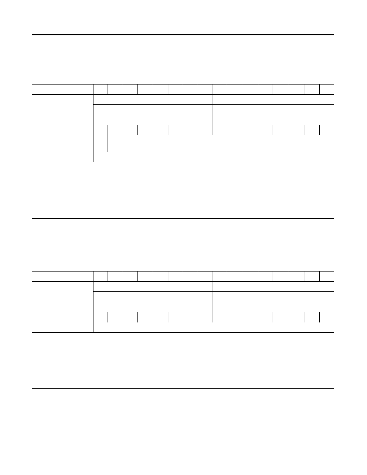
Default Data Map for the Thermocouple Input Module (catalog number 1734-IT2I)
15 14 13 12 11 10 09 08 07 06 05 04 03 02 01 00
Produces (scanner Rx) Input Channel 0 - High Byte Input Channel 0 - Low Byte
Input Channel 1 - High Byte Input Channel 1 - Low Byte
Status Byte for Channel 1 Status Byte for Channel 0
OR UR HHA LLA HA LA CM CF OR UR HHA LLA HA LA CM CF
OR UR Cold Junction Temperature
(Selectable: Channel 0, Channel 1, or Average of both Channel 0 and 1)
Consumes (scanner Tx) No consumed data
Where: OR = Overrange; 0 = no error, 1 = fault (value went above selected range)
UR = Underrange; 0 = no error, 1 = fault (value went below selected range)
HHA = High/High Alarm; 0 = no error, 1 = fault (value went below setpoint
LLA = Low/Low Alarm; 0 = no error, 1 = fault (value went below setpoint
HA = High Alarm; 0 = no error, 1 = fault (value went below setpoint
LA = Low Alarm; 0 = no error, 1 = fault (value went below setpoint)
CM = Calibration Mode; 0 = normal, 1 = calibration mode
CF = Channel Fault status; 0 = no error, 1 = fault
About POINT I/O Modules 3
Default Data Map for the RTD Input Module (catalog numbers 1734-IR2, and 1734-IR2E)
15 14 13 12 11 10 09 08 07 06 05 04 03 02 01 00
Produces (scanner Rx) Input Channel 0 - High Byte Input Channel 0 - Low Byte
Input Channel 1 - High Byte Input Channel 1 - Low Byte
Status Byte for Channel 1 Status Byte for Channel 0
OR UR HHA LLA HA LA CM CF OR UR HHA LLA HA LA CM CF
Consumes (scanner Tx) No consumed data
Where: OR = Overrange; 0 = no error, 1 = fault (value went above selected range)
UR = Underrange; 0 = no error, 1 = fault (value went below selected range)
HHA = High/High Alarm; 0 = no error, 1 = fault (value went below setpoint)
LLA = Low/Low Alarm; 0 = no error, 1 = fault (value went below setpoint)
HA = High Alarm; 0 = no error, 1 = fault (value went below setpoint)
LA = Low Alarm; 0 = no error, 1 = fault (value went below setpoint)
CM = Calibration Mode; 0 = normal, 1 = calibration mode
CF = Channel Fault status; 0 = no error, 1 = fault
Publication 1734-UM004F-EN-E - December 2012
Page 14
4 About POINT I/O Modules
Data Format (1734-IT2I, 1734-IR2, and 1734-IR2E modules)
You must choose a module data format in your user program. Select the
format. These are four predefined scales and one custom scale.
Data Formats
mV Custom Scale
⋅ C Celsius Predefined Scale
⋅ F Fahrenheit
⋅ KKelvin
⋅ R Rankine
°C, F, °R, and °K returns data in tenths of a degree (250 implies 25.0 °).
For the 1734-IR2E,
(250 implies 2.50
⋅ C, ⋅ F, ⋅ R, and ⋅ K returns data in hundreths of a degree
⋅ ). If scaling is set to 10,000 and 20,000, the module returns
hundredths of an ohm (12345 implies 123.45).
For the 1734-IR2, if using ohms, the default data returned is in tenths of ohms
(1234 implies 123.4 Ω).
For the 1734-IT2, if using mV, the default data is returned in hundredths of a
mV, or tens of a μV (3500 implies 35.00
⋅ ).
If the input scale is custom scale, you can specify scaling points as shown in
the table.
1734-IT2I Thermocouple Input Module 1734-IR2 RTD Input Module
Thermocouple
Ty pe
mV 0 mV 70mV Ohms 100 Ω 500 Ω
Type B 212 °F (100 °C) 1832 °F (1000 °C) 100 Ω Ptα = 0.00385 Euro 32 °F (0 °C) 932 °F (500 °C)
Type C 32 °F (0 °C) 4199 °F (2315 °C) 200 Ω Ptα = 0.00385 Euro 32 °F (0 °C) 932 °F (500 °C)
Type E 32 °F (0 °C) 1832 °F (1000 °C) 100 Ω Ptα = 0.003916 U.S. 32 °F (0 °C) 932 °F (500 °C)
Type J 32 °F (0 °C) 1832 °F (1000 °C) 200 Ω Ptα = 0.003916 U.S. 32 °F (0 °C) 932 °F (500 °C)
Type K 32 °F (0 °C) 1832 °F (1000 °C) 10 Ω Cuα = 0.00427 32 °F (0 °C) 482 °F (250 °C)
Low Scaling
Endpoint
High Scaling
Endpoint
RTD Type Low Scaling
Endpoint
High Scaling
Endpoint
Type N 32 °F (0 °C) 1832 °F (1000 °C) 100 Ω Niα = 0.00618 32 °F (0 °C) 482 °F (250 °C)
Type R 32 °F (0 °C) 1832 °F (1000 °C) 120 Ω Niα = 0.00672 32 °F (0 °C) 482 °F (250 °C)
Type S 32 °F (0 °C) 1832 °F (1000 °C) 120 Ω Niα = 0.00618 32 °F (0 °C) 482 °F (250 °C)
Type T 32 °F (0 °C) 212 °F (100 °C)
Publication 1734-UM004F-EN-E - December 2012
Page 15

1734-IR2E RTD Input Module
About POINT I/O Modules 5
Use Module Alarms
RTD Type Low Scaling
Endpoint
O hms 100 Ω 200 Ω
100 Ω Ptα = 0.00385 Euro 32 °F (0 °C) 572 °F (300 °C)
POINT I/O modules are capable of generating the following alarms.
•Overrange
•Underrange
• Level (low-low, low, high, high-high)
• Cold-junction Compensation (CJC) Fault (1734-IT2 only)
•Open-wire Detection
High Scaling
Endpoint
Overrange Alarm (1734-IT2I, 1734-IR2, and 1734-IR2E modules)
The channel overrange alarm is set if the input is greater than the maximum
temperature (thermocouple or RTD range dependent), millivolt (+75 mV) or
resistance (600 Ω) range value, or above the maximum range of the
thermocouple or RTD.
The cold junction compensator has its own overrange alarm. If the CJC
temperature goes above 70 ⋅ C, the overrange alarm is set.
Underrange Alarm (1734-IT2I, 1734-IR2, and 1734-IR2E modules)
The channel underrange alarm is set if the input is less than the minimum
temperature (thermocouple or RTD range dependent), millivolt (-75 mV) or
resistance (10 Ω) range value, or below the minimum range of the
thermocouple or RTD.
The cold junction compensator has its own underrange alarm. If the CJC
temperature goes below 0 ⋅ C, the underrange alarm is set.
Level Alarms (1734-IT2I, 1734-IR2, and 1734-IR2E modules)
The following level alarms are available.
•Low
Publication 1734-UM004F-EN-E - December 2012
Page 16

6 About POINT I/O Modules
• Low-Low
•High
•High-High
When the channel input goes below a low alarm or above a high alarm, a bit is
set in the data table. All Alarm Status bits can be read individually or by
reading the Channel Status Byte (Bits 2...5 for channel 0; bits 10...13 for
channel 1).
You can configure each channel alarm individually.
Open-wire Alarm (1734-IT2I, 1734-IR2, and 1734-IR2E modules)
The module has the ability to check for a broken or detached wire. In any
mode, if a broken/detached lead is detected, the data value is forced to
maximum and the overrange alarm is set. Once the alarm is issued, it remains
active as long as the input signal is faulted.
Cold Junction Compensation (1734-IT2I module)
Chapter Summary
When using thermocouples, cold junction compensation is required at the
termination of the thermocouple wire. Accomplish a cold junction in the
following ways:
• Enter an estimated temperature.
• Use a 1734-TBCJC mounting base (recommended).
• Use external cold junction compensators.
Entering an estimated temperature is the least accurate way for CJC
compensation. Using the compensation built-into the 1734-TBCJC provides
the easiest and most accurate way.
An open CJC causes the CJC input to point to the maximum temperature
value for the selected input type. This causes an alarm to be set. Once the
alarm is issued, it remains active as long as the input signal is faulted (above
maximum).
In this chapter you were given an overview of the 1734 family of modules. The
next chapter walks you through installing your module.
Publication 1734-UM004F-EN-E - December 2012
Page 17
Install the Module
ATTENTION
Chapter
2
Overview
Read this chapter for information about how to install and wire RTD and
thermocouple modules. The following table lists where to find specific
information in this chapter.
Topic Page
Install the Mounting Base 8
Install an I/O Module 10
Install the Removable Terminal Block 12
Remove a Mounting Base 13
Wire the Modules 14
Chapter Summary 16
The RTD module uses a 1734-TB or 1734-TBS mounting base assembly with
1734-RTB removable terminal block (RTB) for RTD wiring.
The thermocouple module uses a 1734-TBCJC mounting base assembly with
1734-CJCRTB removable terminal block with built-in cold junction
compensation for thermocouple inputs.
Preventing Electrostatic Discharge
This equipment is sensitive to electrostatic discharge, which can
cause internal damage and affect normal operation. Follow
these guidelines when you handle this equipment:
• Touch a grounded object to discharge potential static.
• Wear an approved grounding wriststrap.
• Do not touch connectors or pins on component boards.
• Do not touch circuit components inside the equipment.
• If available, use a static-safe workstation.
• When not in use, store the equipment in appropriate static-safe
packaging.
7 Publication 1734-UM004F-EN-E - December 2012
Page 18
8 Install the Module
ATTENTION
Environment and Enclosure
This equipment is intended for use in a Pollution Degree 2
industrial environment, in overvoltage Category II
applications (as defined in IEC publication 60664-1), at
altitudes up to 2000 m (6562 ft) without derating.
This equipment is considered Group 1, Class A industrial
equipment according to IEC/CISPR Publication 11. Without
appropriate precautions, there may be potential
difficulties ensuring electromagnetic compatibility in other
environments due to conducted as well as radiated
disturbance.
This equipment is supplied as open-type equipment. It
must be mounted within an enclosure that is suitably
designed for those specific environmental conditions that
will be present and appropriately designed to prevent
personal injury resulting from accessibility to live parts.
The interior of the enclosure must be accessible only by
the use of a tool. Subsequent sections of this publication
may contain additional information regarding specific
enclosure type ratings that are required to comply with
certain product safety certifications.
Install the Mounting Base
See NEMA Standards publication 250 and IEC publication
60529, as applicable, for explanations of the degrees of
protection provided by different types of enclosure. Also,
see the appropriate sections in this publication, as well as
the Allen-Bradley publication 1770-4.1
Automation Wiring and Grounding Guidelines, for
additional installation requirements pertaining to this
equipment.
The wiring base assembly (1734-TB or 1734-TBS) consists of the following:
• Mounting base, catalog number 1734-MB
• Removable terminal block, catalog number 1734-RTB or 1734-RTBS
The wiring base assembly (1734-TBCJC) consists of the following:
• Mounting base, catalog number 1734-MB
• Removable terminal block, catalog number 1734-RTBCJC
, Industrial
Publication 1734-UM004F-EN-E - December 2012
Page 19
Install the Module 9
ATTENTION
ATTENTION
Therm
ocou
ple
Input
Module
Status
Network
Status
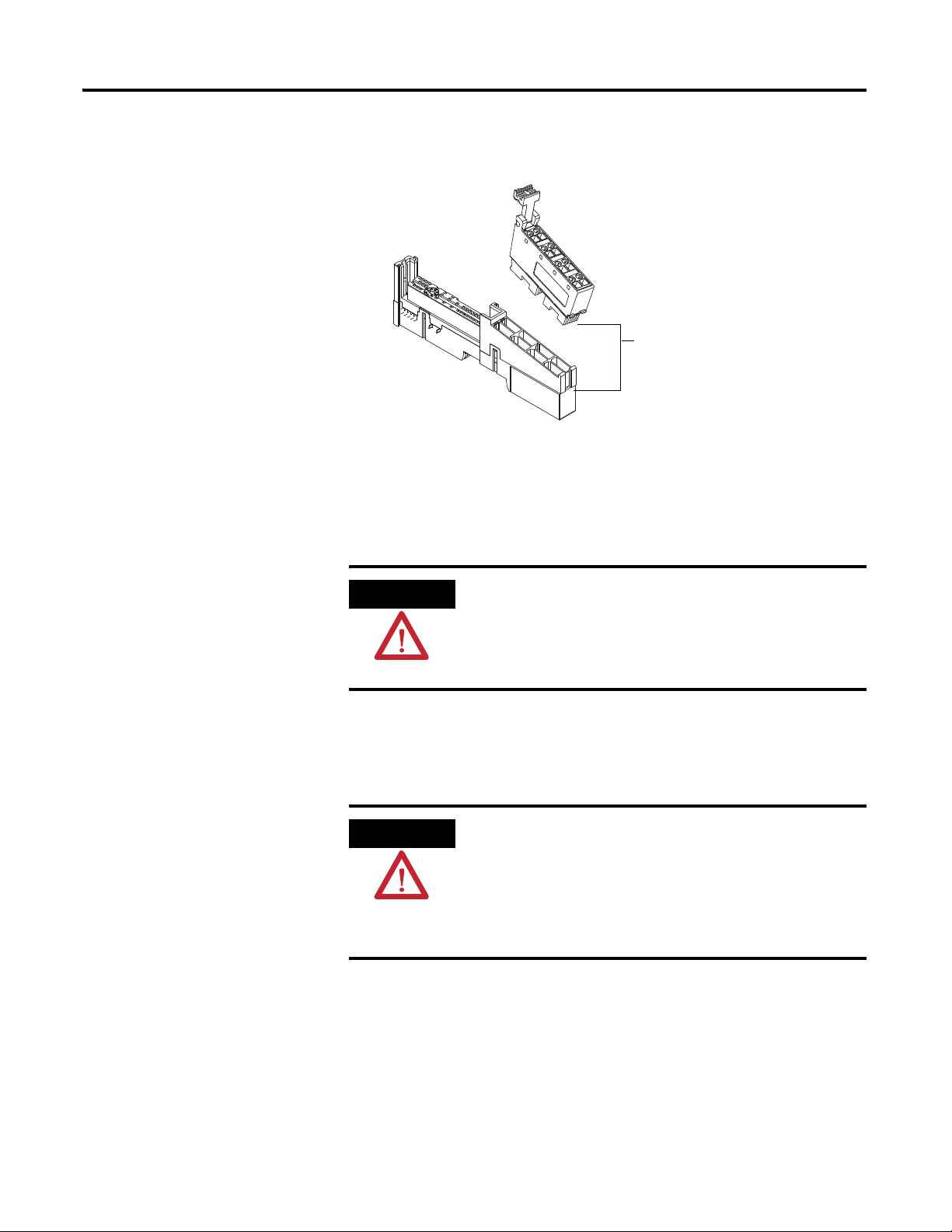
N
O
D
E
:
0
1
1
7
3
4
IT
2
I
Removable terminal
block (1734-RTBCJC)
Insertable
I/O module
RTB Removal
Handle
Slide-in writable label
Interlocking
side pieces
Mechanical keying
(orange)
Module wiring
diagram
DIN rail locking
screw (orange)
Module locking
mechanism
Mounting base
46008
POINT I/O is grounded through the DIN rail to chassis ground.
Use zinc-plated, yellow-chromated steel DIN rail to assure
proper grounding. The use of DIN rail materials (such as
aluminum and plastic) that can corrode, oxidize, or are poor
conductors can result in improper or intermittent grounding.
Secure DIN rail to mounting surface approximately every
200 mm (7.8 in.).
You can install the assembly, or just the mounting base.
Follow this procedure to install the mounting base/wiring base assembly on
the DIN rail.
1. Position the mounting base (wiring base) assembly vertically above the
installed units (adapter, power supply, or existing module).
2. Slide the mounting base down so that the interlocking side pieces
engage the adjacent module or adapter.
Do not discard the end cap shipped with an adapter or
communication interface. Use this end cap to cover the exposed
interconnections on the last mounting base on the DIN rail.
Failure to do so could result in equipment damage or injury from
electric shock.
1734-IT2I shown
Publication 1734-UM004F-EN-E - December 2012
Page 20

10 Install the Module
46003
WARNING
3. Press firmly to seat the mounting base on the DIN rail.
The mounting base snaps into place.
Module
Status
Network
Status
N
ODE:
24VDC
Source
Output
0
1
2
3
1734
OB4E
4. Repeat this procedure for the next mounting base assembly.
Install an I/O Module
Install the module before or after base installation. Make sure you correctly
keyed the mounting base before installing the module into the mounting base.
In addition, make sure you positioned the mounting base locking screw
horizontal, referenced to the base.
When you insert or remove the module while backplane power
is on, an electrical arc can occur. This could cause an explosion
in hazardous location installations.
Be sure that power is removed or the area is nonhazardous
before proceeding. Repeated electrical arcing causes excessive
wear to contacts on both the module and its mating connector.
Worn contacts may create electrical resistance that can affect
module operation.
1. Using a bladed screwdriver, rotate the keyswitch on the mounting base
clockwise till the number required for the type of module you are
installing aligns with the notch in the base.
Publication 1734-UM004F-EN-E - December 2012
Page 21

Install the Module 11
4
5
6
7
8
1
2
3
Turn the keyswitch to align
the number with the notch.
Notch
(position 6 shown)
Make sure the DIN rail locking
screw is in the horizontal position.
1734-RTD - Position 6
1734-IT2I - Position 6
2. Make certain the DIN rail locking screw is in the horizontal position,
noting that you cannot insert the module if the locking mechanism is
unlocked.
Publication 1734-UM004F-EN-E - December 2012
Page 22
12 Install the Module
24VD
C
Source
Output
Module
Status
Netw
ork
Status
1734
OB4E
NODE:
0
1
2
3
44012
3. Insert the module straight down into the mounting base and press to
secure, locking the module into place.
Install the Removable Terminal Block
A removable terminal block comes with your mounting base assembly. To
remove, pull up on the RTB handle to remove the base and replace, as
necessary, without removing any of the wiring. To reinsert the removable
terminal block, proceed as follows.
Publication 1734-UM004F-EN-E - December 2012
Page 23
Install the Module 13
WARNING
Hook the RTB end into the
mounting base end, and
rotate until it locks into place.
WARNING
1. Insert the RTB end opposite the handle into the base unit, which has a
curved section that engages with the mounting base.
2. Rotate the terminal block into the mounting base until it locks itself in
place.
3. If an I/O module is installed, snap the RTB handle into place on the
module.
Remove a Mounting Base
When you connect or disconnect the removable terminal block
(RTB) with field-side power applied, an electrical arc can occur.
This could cause an explosion in hazardous location
installations. Be sure that power is removed or the area is
nonhazardous before proceeding.
To remove a mounting base, you must remove any installed module, and
remove the removable terminal block (if wired).
When you connect or disconnect the removable terminal block
(RTB) with field-side power applied, an electrical arc can occur.
This could cause an explosion in hazardous location
installations.
Be sure that power is removed or the area is nonhazardous
before proceeding.
1. Unlatch the RTB handle on the I/O module.
2. Pull on the RTB handle to remove the removable terminal block.
3. Press in on the module lock on the top of the module, and pull up on
the I/O module to remove from the base.
Publication 1734-UM004F-EN-E - December 2012
Page 24
14 Install the Module
WARNING
43923
Module status
Network status
Status of input 0
Status of input 1
0+
Shield
0-
1+
1-
4. Remove the module to the right of the base you are removing, noting
that the interlocking portion of the base sits under the adjacent module.
5. Use a small-bladed screwdriver to rotate the orange DIN rail locking
screw on the mounting base to a vertical position. releasing the locking
mechanism.
6. Lift the mounting base straight up to remove.
Wire the Modules
To wire the thermocouple input modules, refer to the figures.
If you connect or disconnect wiring while the field-side power
is on, an electrical arc can occur. This could cause an explosion
in hazardous location installations. Be sure that power is
removed or the area is nonhazardous before proceeding.
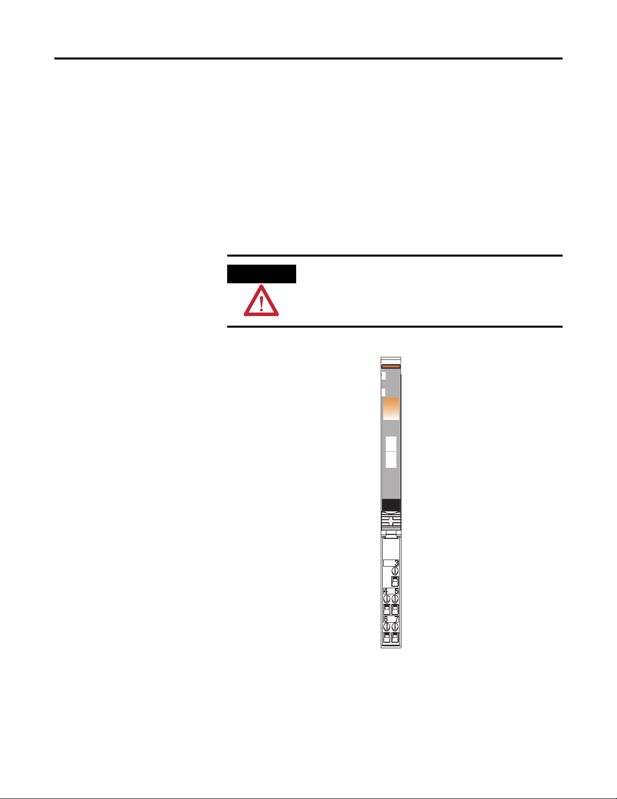
1734-IT2I Module Overview
Module
Status
Network
Status
NODE:
Thermocouple
Input
0
1
1734
IT2
Publication 1734-UM004F-EN-E - December 2012
Page 25
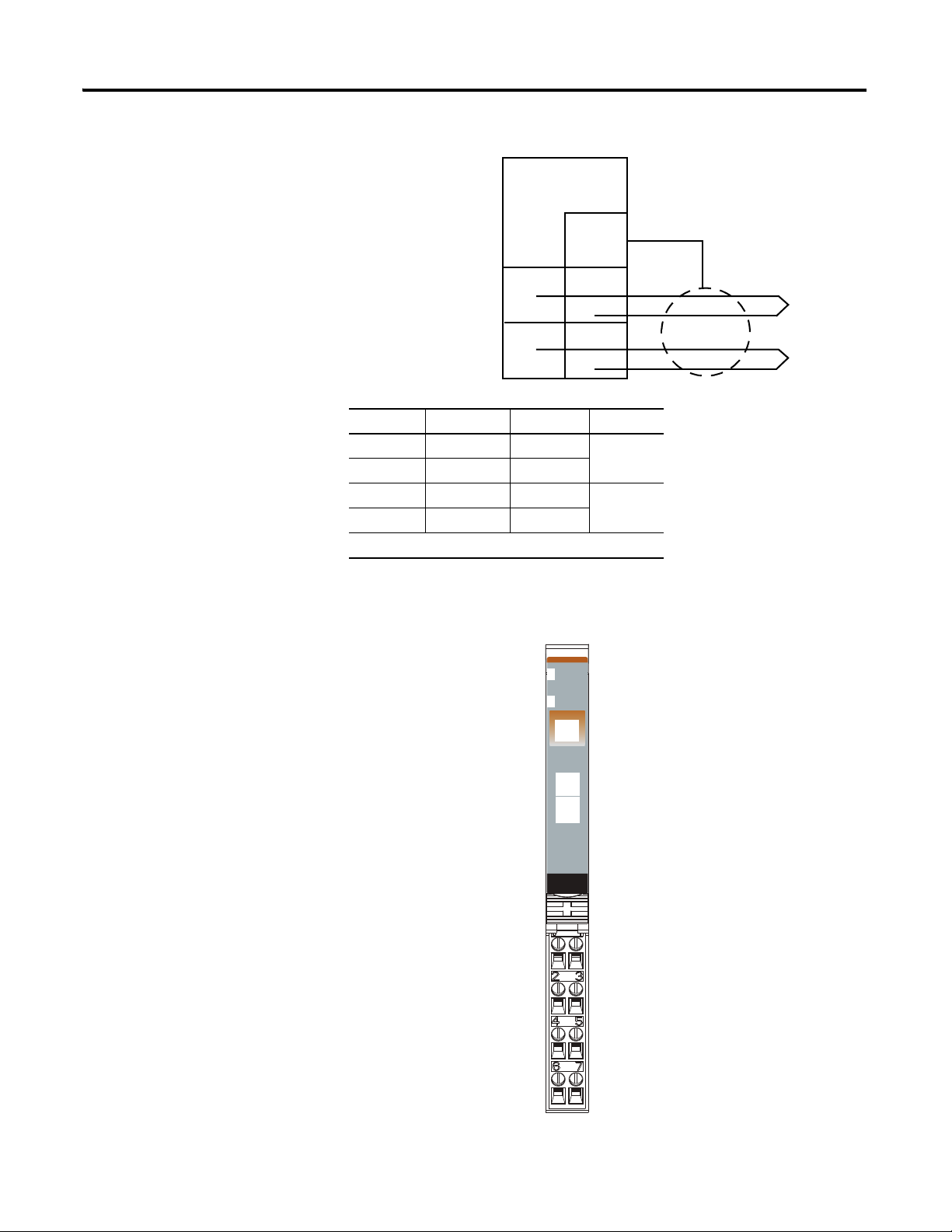
Wiring Diagram
Shield
0+
0-
1-
1+
3
5
7
4
6
Thermocouple 0
Thermocouple 1
0+ = Input channel 0 High
0- = Input channel 0 Low
1+ = Input channel 1 High
1- = Input channel 1 Low
Shld = Shield
46000
Module Status
Network Status
Status of Input 0
Status of Input 1
Input 0/A HIgh Input
Input 0/B Low Input
RET 0
Shield
Input 1/A High Input
Input 1/B Low Input
Shield
RET 1
Input Channel Power Limits
Channel Input High Input Low Shield
0+ 4 3
0- 5
1+ 6 3
1- 7
Power is provided by the internal power bus.
Install the Module 15
To wire RTD modules, refer to the figures.
1734-IR2, 1734-IR2E Module Overview
Module
Status
Network
Status
NODE:
RTD
Input
0
1
1734
IR2
Publication 1734-UM004F-EN-E - December 2012
Page 26
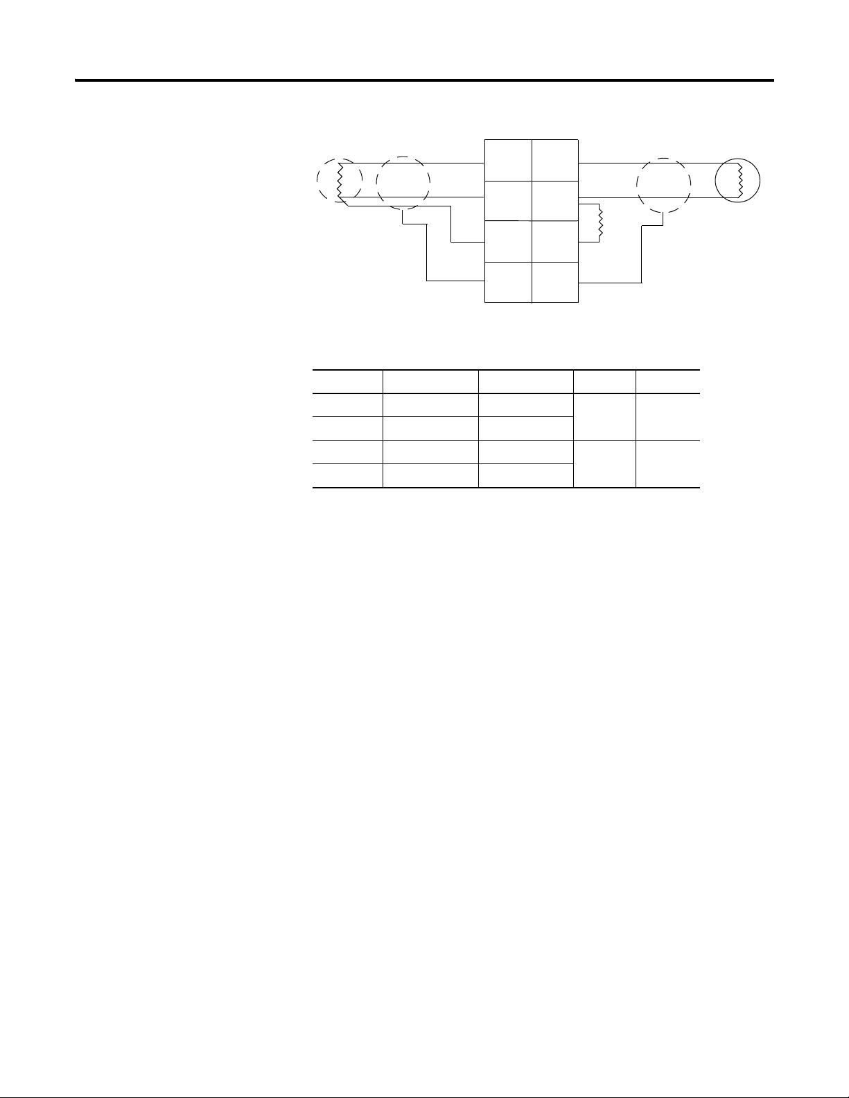
16 Install the Module
In 0/A In 1/A
In 1/BIn 0/B
RET 0 RET 1
ShieldShield
3-wire
RTD
In = Input channel
RET = Sensor return
Shield = Sensor cable shield
3
5
0
1
2
4
2-wire
RTD
6
7
When using 2-wire RTDs,
Insert 1 Ω resistor IN/B to
RET.
1 Ω
resistor
Wiring Diagram
Input Channel Power Limits
Channel High Signal (+) Low Signal (-) Return Shield
In 0/A 0 4 6
In 0/B 2
In 1.A 1 5 7
Chapter Summary
In 1/B 3
This chapter explained how to install and wire the modules. The next chapter
describes how to configure your POINT I/O Thermocouple and RTD
Modules.
Publication 1734-UM004F-EN-E - December 2012
Page 27

Configure Your Module
Chapter
3
Overview
Configuration Overview
This chapter describes how to configure your thermocouple input module
with RSNetWorx.
Topic Page
Configuration Overview 17
Commissioning a Node 17
Add the Adapter to Your Network 19
Set the Thermocouple Input Module Parameters
Using RSNetWorx
Configure Your Thermocouple Input Module 24
Set the RTD Input Module Parameters Using
RSNetWorx
Configure Your RTD Input Module 31
Check I/O Status and View the EDS File 36
Chapter Summary 37
Configuring POINT I/O modules is as easy as point and click. RSNetWorx
lets you identify the network and configure the I/O modules
with Electronic Data Sheet (EDS) files - just point to the field and click your
selection.
22
29
To obtain EDS files for use in configuration, go to
http://www.ab.com/networks/eds
In this chapter, you learn how to do the following.
• Add the adapter to the system.
• Commission individual modules in the system.
• Set the individual modules parameters.
Commissioning a Node
17 Publication 1734-UM004F-EN-E - December 2012
Here are the methods for commissioning nodes.
• Use the RSNetWorx commissioning pull-down dialog.
• Use the Sequential Auto Addressing feature.
• Use third-party configuration software.
.
Page 28

18 Configure Your Module
IMPORTANT
ATTENTION
Using the RSNetWorx Commissioning Tool
Use the RSNetWorx commissioning tool to commission devices (set the node
address and the data rate parameters) that are:
• connected to a DeviceNet network.
• connected via a point-to-point connection.
The node commissioning tool works through RSLinx; RSNetWorx does not
have to be online when performing the operation.
Before you can add any device to a DeviceNet network, it must be
commissioned. This means that a node address and a data rate must be
programmed into the device. Some devices are precommissioned, meaning a
node address (usually set to 63) and a data rate (usually set to 500 Kbps) are
programmed into the device at the factory prior to shipment. Other devices
muse be commissioned in the field. Once a device is commissioned and
attached to a network, you can use the RSNetWorx for DeviceNet node
commissioning tool to edit the node address and data rate that were set
previously.
Exercise caution while editing node addresses when on a
network. When you apply a new node address, it immediately
overwrites the node address data in the device currently
specified. If you decide to reassign node addresses, you should
first determine the order you use so that all the devices still
have unique node addresses when you are finished.
For example, if two of the devices on your network are a photoelectric sensor
and a hand controller, and you accidentally change the node address of the
hand controller to be the same as that of the photoelectric sensor, then the
photoelectric sensor no longer has a unique address, which means that it is not
be able to provide data to the scanner. If you cannot access a device because
you have used its node address for another device, you have to remove it from
the network, recommission it, then reinstall it on the network.
Do not change the data rate of devices while they are
connected to a network. Erratic operation may result. We
recommend that if you need to change the data rate of a device,
you should remove it from the network, establish a
point-to-point connection between the PC, which hosts the
RSNetWorx for DeviceNet software, and the target device,
recommission it, and then, reconnect it to the network.
Publication 1734-UM004F-EN-E - December 2012
Page 29

Configure Your Module 19
IMPORTANT
Use Sequential Auto Addressing
Sequential Auto Addressing (SAA) reassigns the node address of every module
to the right of the one you select. Each module changes its node address to
one greater than its neighbor.
Make sure the node address of the selected module is the
desired value before issuing the SAA command.
When this command is set, each module to the right gets a new address one
greater than its neighbor. The addressing ripples through a line of POINT I/O
modules, assigning a node number to each module installed in a mounting
base.
Perform this procedure to Auto Address a line of POINT I/O modules.
1. Set the address of the first module you want to address.
Add the Adapter to Your Network
2. Set the Auto Address command to Sequential Address.
3. All modules in line reset with new sequential addresses.
An example is if 5 POINT I/O modules are in a line, and the address of the
first module is 10. After the Sequential Address command is sent to the first
module, the node address of the line is: 10, 11, 12, 13, and 14.
Use Third Party Configuration Software
When using third party configuration software, simply load the EDS files into
the software and follow the designer’s instructions.
You can use the RSNetWorx for DeviceNet software, or some other
configuration tool for DeviceNet, to configure your module. If the EDS files
are not in your software, you can get them at
http://www.ab.com/networks/eds/
You can configure the module while it is:
.
• online.
• offline.
Publication 1734-UM004F-EN-E - December 2012
Page 30

20 Configure Your Module
1. Click here to expand the list of
communication adapters.
2. Double-click here to choose the
scanner. You can also click and
drag the scanner name onto
the network.
Make sure you choose the
1734-ADN POINT I/O Scanner.
The scanner appears
on the network.
1. Click here to expand the list of
Specialty modules.
2. Double-click the catalog number
to choose the module. You can
also click and drag the module
name onto the network.
This chapter shows configuration in the online mode. Configuration dialogs
appear similar in both modes. The primary difference is that if you make
changes offline, you must go online before the configuration changes take
effect.
Perform this procedure to add a communication device.
1. Start the RSNetWorx for DeviceNet software.
2. Add the communication adapter as shown in the figure.
In this case, the chosen device was a 1770-KFD RS232 Interface.
Publication 1734-UM004F-EN-E - December 2012
Add I/O Modules to Your Network POINTBus
After you add the communication device, you must add the POINT I/O
modules connected to the scanner on the POINTBus.
Add modules as shown in the figure.
Page 31

Configure Your Module 21
1. Go to the Tools pull-down menu.
2. Select Node Commissioning.
3. Click Browse.
4. Select the module to change.
5. The node commissioning dialog
returns. It displays the node number
and data rate.
6. Change the node number and
Apply, noting that the dialog then
identifies the new setting.
7. Click Close to continue.
4
2
3
1
5
6
IMPORTANT
The out-of-the-box node setting for 1734 modules is 63. You can change the
setting by using the node commissioning tool. The node commissioning tool is
available either online or offline.
If you commission a node online, you must power down your
system before the change takes place.
Publication 1734-UM004F-EN-E - December 2012
Page 32

22 Configure Your Module
IMPORTANT
1. Right-click the module.
2. Click Properties to configure.
You can also left-click the module or name.
These are the tabs you click to
view the options.
Set the Thermocouple Input
After adding the module to the network, you must configure the modules for
use.
Module Parameters Using
RSNetWorx
Configure the modules as shown in the figure.
You see a dialog with a series of tabs. Each tab provides options view or edit.
The tabs are shown in the following figure.
This chapter shows configuration in the online mode. Changes
set in this mode take effect when you download to the
individual module.
Publication 1734-UM004F-EN-E - December 2012
Refer to these dialogs for an explanation of features.
Page 33

The module name appears here.
Type a description here.
The module address appears
here. (This field is read-only.)
This dialog also shows the
module’s device identity.
These fields are read-only.
At any point, you can click here to
finish changing configuration
parameters.
IMPORTANT: If configuration
changes are made in
offline mode they do
not take effect until
the system goes
online.
Click the Device parameters tab to
get to the dialog for setting the
parameters.
This dialog appears after clicking the
Device parameters tab. If you want
the existing parameters uploaded
from the module, select Upload.
The following dialog then shows the
existing parameters set on the
module.
Use this pull-down menu to edit or view
the parameters. Available choices are:
POINTBus
Status
Configuration
Configure Your Module 23
Setting Parameters
Publication 1734-UM004F-EN-E - December 2012
Page 34

24 Configure Your Module
IMPORTANT
Configure Your Thermocouple Input Module
Configuration can be divided into two categories: Basic Set-up Parameters and
Advanced Setup Parameters.
Basic Set-up Parameters
The basic parameters you need to set for the thermocouple module consist of:
• Temperature units - Select how the input is linearized:
– mV/Custom Scale (default)
– Celsius
– Fahrenheit
– Kelvin
– Rankine
• Thermocouple type - Choose the type of sensor for this input. The
module performs the linearization of the selected type.
– mV (No Linearization)
– Type B
– Type C
– Type E
– Type J
– Type K
– Type N
– Type R
– Type S
– Type T
• Cold Junction Enable - This bit enables or disables the cold junction
linearization. If enabled, the proper cold junction compensation value is
applied to the selected thermocouple. If disabled, the data (CJ
Temperature) is still available but not applied to the input. If the Cold
Junction Compensation Removable Terminal Block is not available, this
parameter should be set to disabled. A cold junction value can be added
using the Cold Junction Offset parameter.
• Cold Junction Produced Data - Selects how the Cold Junction Data is
returned in the Produced IO message. The last two bytes of the
produced message contain one of the following.
– None (zeros)
– Channel 0 (default)
– Channel 1 - Average of both channels
The Over/Under Range status is also included in the last two
bytes, along with the cold junction value.
Publication 1734-UM004F-EN-E - December 2012
Page 35

Configure Your Module 25
Advanced Setup Parameters
Advanced parameters you can set for the thermocouple module consist of:
• Notch filter - Select the Notch Filter for the analog to digital converter.
At higher frequencies, faster sample rates are possible
– 50 Hz
– 60 Hz (default)
– 100 Hz
– 120 Hz
– 200 Hz
– 240 Hz
– 300 Hz
– 400 Hz
– 480 Hz
If the filter value is changed, the module may require calibration to meet
specifications.
• Digital filter - A digital filter is available on this module. You set a time
constant which is used in the equation:
Yn = Yn-1 + (dt / (dt + TA) * (Xn-Yn-1)
Where: Yn = new data
Yn-1 = old data
dt = Channel Update Rate in milliseconds
T
= digital filter time constant
A
Xn = present unfiltered data
TA can be an integer from 0 to 10,000 ms. If set to 0, the filter is
disabled.
• Cold Junction Offset - If you do not use a 1734-RTBCJC removable
terminal block, enter an estimate for the junction temperature here.
Enter the value in hundreths of degrees Celsius, even if another scale is
selected (2500 implies 25.00 °C).
• Enable alarms latch - If enabled, alarms for this channel latch
FAULTED until a Latch Reset command is received.
The alarms effected are:
– Input Status
– Low and High level
– Range
• Disable alarms - If Alarms are Disabled, all alarms for this channel show
No FAULT. This is useful for unused channels.
Publication 1734-UM004F-EN-E - December 2012
Page 36

26 Configure Your Module
To configure your module,
select Configuration and
modify the parameters as
desired for your application.
When complete, download to
your module by clicking the
Download to Device button.
You can download each
change as you make it using
“Single,” or download all your
changes using “All.” If you
press the “Apply” button, only
the selected parameter is
downloaded to the module.
Click here when finished.
• Level alarms - low-low, low, high, and high-high - any value from
-32,768...+32,767 can be entered.
• Scaling - Values returned when input is at low scale value or high scale
value. The low and high scale points are different for each sensor input:
Thermocouple Scaling limits
Thermocouple
Ty pe
mV 0 mV 70 mV
Type B 212 °F (100 °C) 1832 °F (1000 °C)
Type C 32 °F (0 °C) 4199 °F (2315 °C)
Type E 32 °F (0 °C) 1832 °F (1000 °C)
Type J 32 °F (0 °C) 1832 °F (1000 °C)
Type K 32 °F (0 °C) 1832 °F (1000 °C)
Type N 32 °F (0 °C) 1832 °F (1000 °C)
Type R 32 °F (0 °C) 1832 °F (1000 °C)
Low Scaling
Endpoint
High Scaling
Endpoint
Publication 1734-UM004F-EN-E - December 2012
Type S 32 °F (0 °C) 1832 °F (1000 °C)
Type T 32 °F (0 °C) 212 °F (100 °C)
To configure your module, select Configuration as shown in the figure.
Configure a module
Use the procedures in the figures that show basic setup and advanced setup,
noting that you complete steps 1-5 during basic setup, then continue with steps
6-10 during advanced setup.
Page 37

1. Select the
temperature scale.
2. Then select the type
of thermocouple:
B
C
E
J
K
N
R
S
T or mV
3. Select cold junction
compensation if desired.
4. Select how the cold
junction data is returned in the produced I/O
message. Select None, channel 0, channel
1, or the average of both channels.
5. Download to the device.
Configure Your Module 27
Basic Setup
Publication 1734-UM004F-EN-E - December 2012
Page 38

28 Configure Your Module
6. Select the notch filter
desired (60 Hz to
480 Hz).
7. Select the digital filter
(select as necessary)
8. Enable or disable the
latching alarms.
9. Enable or disable the
alarms.
10. Apply and download to
the device.
Advanced Setup
Publication 1734-UM004F-EN-E - December 2012
Page 39

Configure Your Module 29
IMPORTANT
1. Right-click the module.
2. Click Properties to
configure.
You can also left click the module or name.
Click these tabs to view the
options.
Set the RTD Input Module Parameters Using RSNetWorx
After adding the module to the network, you must configure the modules for
use.
This chapter shows configuration in the online mode. Changes
set in this mode take effect when you download to the
individual module.
Configure the modules as shown.
You see a dialog with a series of tabs. Each tab provides options to view or
edit. Refer to the figure to see the tabs.
Refer to these dialogs for an explanation of features.
Publication 1734-UM004F-EN-E - December 2012
Page 40

30 Configure Your Module
The module name appears here.
Type a description here.
The module address appears
here. (This field is read-only.)
This dialog also shows the
module’s device identity.
These fields are read-only.
At any point, click here to finish changing
configuration parameters.
If configuration changes are made in offlin
mode, they do not take effect until the
system goes online.
Click the Device parameters tab to
get to the dialog for setting the
parameters.
This dialog appears after you click
the Device parameters tab. If you
want the existing parameters
uploaded from the module, select
Upload. The following dialog then
shows the existing parameters set
on the module.
Use this pull-down menu to edit or view the
parameters. Available choices are:
POINTBus
Status
Configuration
Setting Parameters
Publication 1734-UM004F-EN-E - December 2012
Page 41

Configure Your Module 31
Configure Your RTD Input Module
Configuration is divided into basic and advanced parameters.
Basic Setup Parameters
The basic parameters you need to set for the RTD module consist of:
• Temperature units – Use the Temperature Scale parameter to select a
predefined scale or a custom scale. Custom Scale allows you to enter the
scaling endpoint values. If using Ohms RTD Type, ignore this
parameter. Predefined Scales include: Celsius(C), Fahrenheit(F),
Kelvin(K), and Rankine(R).
Scaling Endpoints for Custom Scale (low & high):
RTD Module Scaling Limits
RTD Type Low Scaling
Endpoint
Ohms 100 Ω 500 Ω
100 Ω Ptα = 0.00385 Euro 32 °F (0 °C) 932 °F (500 °C)
200 Ω Ptα = 0.00385 Euro 32 °F (0 °C) 932 °F (500 °C)
100 Ω Ptα = 0.003916 U.S. 32 °F (0 °C) 932 °F (500 °C)
200 Ω Ptα = 0.003916 U.S. 32 °F (0 °C) 932 °F (500 °C)
High Scaling
Endpoint
10 Ω Cuα = 0.00427 32 °F (0 °C) 482 °F (250 °C)
100 Ω Niα = 0.00618 32 °F (0 °C) 482 °F (250 °C)
120 Ω Niα = 0.00672 32 °F (0 °C) 482 °F (250 °C)
120 Ω Niα = 0.00618 32 °F (0 °C) 482 °F (250 °C)
RTD Type (1734-IR2E) Low Scaling
Endpoint
Ohms 100 Ω 200 Ω
100 Ω Ptα = 0.00385 Euro 32 °F (0 °C) 572 °F (300 °C)
High Scaling
Endpoint
• RTD type – Select the RTD type that the input uses. Valid types are
shown in the table.
• Copper RTD Offset – If using the copper RTD, this is the error of the
Copper RTD (10
250 in hundredths of Ohms (such as 361 = 3.61
Ω Cu427) in Ohms. Enter a value between -250 and
Ω). This value is added
to the input reading before linearization.
Publication 1734-UM004F-EN-E - December 2012
Page 42

32 Configure Your Module
Advanced Setup Parameters
Advanced parameters you can set for the RTD module consist of:
• Notch filter – Select the Notch Filter for the analog to digital converter.
At higher frequencies, faster sample rates are possible
– 50 Hz
– 60 Hz (default)
– 100 Hz
– 120 Hz
– 200 Hz
– 240 Hz
– 300 Hz
– 400 Hz
– 480 Hz
If the filter value is changed, the module may require calibration to meet
specifications.
• Digital filter – A digital filter is available on this module. You set a time
constant that is used in the equation:
Yn = Yn-1 + (dt / (dt + TA) * (Xn-Yn-1)
Where: Yn = new data
Yn-1 = old data
dt = Channel Update Rate in milliseconds
T
= digital filter time constant
A
Xn = present unfiltered data
TA can be an integer from 0 to 10,000 ms. If set to 0, the filter is
disabled.
• Enable alarms latch – If enabled, alarms for this channel latch
FAULTED until a Latch Reset command is received.
The alarms effected are:
– Input Status
– Low and High level
– Range
• Disable alarms – If Alarms are Disabled, all alarms for this channel
show No FAULT. This is useful for unused channels.
• Level alarms – low-low, low, high, and high-high.
Publication 1734-UM004F-EN-E - December 2012
Page 43

Configure Your Module 33
1. To configure your RTD module,
select Configuration and
modify the parameters as
desired for your application.
2. When complete, download to
your module by clicking the
Download to Device button.
You can download each
change as you make it using
Single, or download all your
changes using All. If you press
the Apply button, only the
selected parameter
downloads to the module.
3. Click here when finished.
• Scaling – Values returned when input is at low scale value or high scale
value. The low and high scale points are different for each sensor input:
RTD Module Scaling Limits
RTD Type Low Scaling
Endpoint
High Scaling
Endpoint
O hms 100 Ω 500 Ω
100 Ω Pt α = 0.00385 Euro 32 °F (0 °C) 932 °F (500 °C)
200 Ω Pt α = 0.00385 Euro 32 °F (0 °C) 932 °F (500 °C)
100 Ω Pt α = 0.003916 U.S. 32 °F (0 °C) 932 °F (500 °C)
200 Ω Pt α = 0.003916 U.S. 32 °F (0 °C) 932 °F (500 °C)
10 Ω Cu α = 0.00427 32 °F (0 °C) 482 °F (250 °C)
100 Ω Ni α = 0.00618 32 °F (0 °C) 482 °F (250 °C)
120 Ω Ni α = 0.00672 32 °F (0 °C) 482 °F (250 °C)
120 Ω Ni α = 0.00618 32 °F (0 °C) 482 °F (250 °C)
RTD Type (1734-IR2E) Low Scaling
Endpoint
High Scaling
Endpoint
O hms 100 Ω 200 Ω
100 Ω Pt α = 0.00385 Euro 32 °F (0 °C) 572 °F (300 °C)
To configure your RTD module, select Configuration as shown in the figure.
Use the procedures in the figures that show basic setup and advanced setup,
noting that you complete steps 1 and 2 during basic setup, then continue with
steps 3…13 during advanced setup.
Publication 1734-UM004F-EN-E - December 2012
Page 44

34 Configure Your Module
1. Select the type of RTD
you are using for
channel 0. Repeat for
channel 1.
2. Then select the scale
for channel 0. Repeat
for channel 1.
This is the error of Copper RTD (10
Ω
Cu427) in O hms. Enter value between
-250 and 250 in hundredths of Ohms
(such as 361 = 3.61
Ω). If you are using a
copper RTD, this value is added to the
input reading before linearization.
Basic Setup
Publication 1734-UM004F-EN-E - December 2012
Page 45

3. Select the digital filter desired.
(Range is 0...10.000 ms.)
6. Select the notch filter.
4. Enable or disable the latching
alarms.
5. Enable or disable the alarms.
7. Apply and download to the device.
Configure Your Module 35
Advanced Setup
Publication 1734-UM004F-EN-E - December 2012
Page 46

36 Configure Your Module
1. Click the I/O Defaults tab to
display the default
characteristics for this module.
This dialog shows the
input/output defaults for the
four modes:
Strobe
Polled
Change of state and
Cyclic
3. Click View File to view
the actual EDS file
(shown).
2. Click the EDS File tab to display the
statistics of the EDS file used to
configure this module.
You can view the actual
EDS file or edit the file.
Check I/O Status and View the EDS File
View the I/O defaults setup and the EDS file by clicking the appropriate tab.
1734-IT2I module
Publication 1734-UM004F-EN-E - December 2012
Page 47

1734-IR2 and 1734-IR2E modules
3. Click View File to
view the actual
EDS file (shown).
2. Click the EDS File tab to display
the statistics of the EDS file used
to configure this module.
1. Click the I/O Defaults tab to display
the default characteristics for this
module.
This dialog shows the
input/output defaults for the
four modes:
Strobe
Polled
Change of state and
Cyclic
Configure Your Module 37
Chapter Summary
This chapter explained how to configure the modules. The next chapter walks
you through how to calibrate your POINT I/O Thermocouple and RTD
Modules.
Publication 1734-UM004F-EN-E - December 2012
Page 48

38 Configure Your Module
Publication 1734-UM004F-EN-E - December 2012
Page 49

Calibrate Your Module
Chapter
4
Overview
When and How to Calibrate
Use this chapter to calibrate the thermocouple/mV module or the RTD input
module. Refer to the table for a summary of what is covered.
Your module is shipped to you already calibrated. If a calibration check is
required, the module must be in a POINT I/O system.
Your Module
Perform module calibration periodically, based on your application. Module
calibration may also be required to remove module error due to aging of
components in your system.
Task Pag e
When and How to Calibrate Your Module 39 Calibration Method 39 Tools and Equipment Required to Calibrate Your Thermocouple Module 39 Calibrate the Thermocouple Input Module 40 Input (mV) Calibration 42 Cold Junction Compensation Calibration 45 Tools and Equipment Required to Calibrate Your RTD Module 48 Calibrate the RTD Input Module 48
Calibration Method
Tools and Equipment
Perform calibration through the I/O configuration software, such as
RSNetWorx and EDS files. If the EDS files are not in your software, get them
online at www.ab.com/networks/eds/
To calibrate your thermocouple module, you need the following tools and
equipment.
.
Required to Calibrate
Your Thermocouple Module
39 Publication 1734-UM004F-EN-E - December 2012
Tool or Equipment Description
Precision Resistors High precision resistors:
1000 Ω, 0.05%, 5 ppm/
3000 Ω, 0.05%, 5 ppm/
or
Calibrated resistor Decade Box, 0.05%
Precision Voltage Source +100 mV, 1 mV resolution - accuracy +
o
C
o
C
3 μV or better
Page 50

40 Calibrate Your Module
IMPORTANT
01 01 01 01 010101
DeviceNet Input
Precision
Voltage
Source
Channel 0
Connect to 4 and 5
Channel 1
Connect to 6 and 7
1734-IT2I
1734-PDN
Shield
0+
0-
1-
1+
Thermocouple 0
Thermocouple 1
Precision Voltage
Source
0+
1+
1734-RTB
CJC
1734-RTB
Precision resistors
0+
1+
0 -
1-
46001
45999
46011
Calibrate the Thermocouple
To calibrate your thermocouple input module, connect the module in a
DeviceNet system similar to that shown in the figure.
Input Module
Module Connection
Apply power to the power supply and module for at least 10
minutes before calibrating the module.
Delete all I/O connections by removing the module from its
master's scan list and inhibiting the module in RSLogix. When
there is no connection present the Network Status Indicator
should flash green.
Publication 1734-UM004F-EN-E - December 2012
Page 51

Calibrate Your Module 41
ATTENTION
Click Device Parameters to
view the parameters.
Access Calibration Parameters in RSNetWorx
1. Double-click the icon of the module to be calibrated to bring up the
General Parameter dialog.
2. Click Device parameters.
The EDS editor may ask you if you want to upload the configuration
from the device.
3. If you do not see the EDS editor dialog, proceed with the next step;
otherwise, from the EDS editor dialog, click Upload.
The dialog box layout varies depending on the version of
RSNetWorx software you are using.
Publication 1734-UM004F-EN-E - December 2012
Page 52

42 Calibrate Your Module
This is the Groups pull-down.
IMPORTANT
4. From the Device Parameters dialog, select Calibration at the Groups
pull-down.
Input (mV) Calibration
Before calibrating the module you need to select the sensor type and download
it to the module.
Perform the following procedure from the Device Parameters dialog.
Apply power to the power supply and module for at least 10
minutes before calibrating the module.
Delete all I/O connections by removing the module from its
master's scan list and inhibiting the module in RSLogix. When
there is no connection present the Network Status Indicator
should flash green.
Publication 1734-UM004F-EN-E - December 2012
Page 53

Calibrate Your Module 43
For input calibration, choose:
Input Channel 0,
Input Channel 1, or
Both Channels.
1. From the Configuration tab, set the Thermocouple Type to mV (no
linearization) for the channel(s) to be calibrated and download to the
module.
2. Open the Device Parameter tab and click Calibration Channel Select to
bring up your channel selections.
3. Select a channel (0 or 1), or select Both Channels.
4. Click Download to Device.
Publication 1734-UM004F-EN-E - December 2012
Page 54

44 Calibrate Your Module
IMPORTANT
Select Accept Low Input and
download to the device.
5. Click Calibration Command, and select Begin Calibration.
6. Click the Download to Device button.
The status indicator of a channel in calibration mode flashes green. The
status indicator of a channel not in calibration turns off.
7. Apply 0.00 mV to the input, referring to the wiring diagram in this
section.
Calibration in millivolts allows the sensor calibration to be
independent of CJC. The cold junction compensation is not
active for the mV input regardless of the CJC setting. The
module must have the exact voltage at its input terminals.
Thermocouple wire or a voltage source that simulates a TC
voltage should not be used.
8. Click Accept Low Input.
Publication 1734-UM004F-EN-E - December 2012
9. Click the Download to Device button.
The status indicator(s) for the channel(s) being calibrated blink(s) green.
Page 55

10. Set the source to 70 mV.
Select Cold Junction 0, Cold
Junction 1, or Both Cold Junction.
Module terminal voltage must be exact.
11. Click Accept High Input.
12. Click the Download to Device button.
Calibrate Your Module 45
Input calibration is now complete. The status indicator should be solid green
(normal) or blinking red (no load). The channel can now be configured to the
type of input desired for normal operation. If an error occurred during
calibration, select Abort Calibration in the Calibration Command parameter to
restore the previous calibration values, and try again.
Cold Junction Compensation Calibration
Perform this procedure from the Device Parameters dialog.
1. Click Calibration Channel Select and select one channel, or both
channels at once.
Publication 1734-UM004F-EN-E - December 2012
Page 56

46 Calibrate Your Module
Click calibration
command and select
Begin CJC calibration.
Then download to the
module.
2. Click Calibration Command and select Begin CJC Calibration.
3. Click the Download to Device button.
4. Using a 1734-RTB removable terminal block, apply 1000 Ω to the
selected CJC channel, referring to the wiring diagram in this section.
5. Select Accept Low CJC and download to the device.
6. Using a 1734-RTB removable terminal block, apply 3000 Ω to the
selected CJC channel.
Publication 1734-UM004F-EN-E - December 2012
Page 57

Calibrate Your Module 47
When the calibration is
accepted by the module, it
sets the Bad Cal Status bit
for the channel to Good
Calibration, as shown
here.
7. Select Accept High CJC and download to the device.
8. If RSNetWorx reports a communication error, or if an error occurred
during this calibration, abort calibration and try again.
Calibration is done as soon as High and Low calibration for the selected
channels is done successfully.
Repeat above steps to calibrate the other channel if you chose to
calibrate only one channel at a time. Both high and low inputs must be
accepted in order for the module to finish calibration.
Calibration is now complete.
If the module does not accept calibration (status indicator still blinking), click
Calibration Command and select Abort Calibration, apply, and start over.
Publication 1734-UM004F-EN-E - December 2012
Page 58

48 Calibrate Your Module
IMPORTANT
01 0101 01 010101
DeviceNet Input
100 Ω for Low;
500 Ω for High
Channel 0
Connect to 0 and 2
Decade
Resistance Box
(0.05% or better)
Channel 1
Connect to 1 and 3
1734-IR21734-PDN
Channel 0
Channel 1
45998
45999
100 Ω for Low;
500 Ω for High
1 Ω resistor
1 Ω resistor
Tools and Equipment Required to Calibrate Your RTD Module
Calibrate the RTD Input Module
To calibrate your RTD module, you need the following tools and equipment.
Tool or Equipment Description
Precision Resistors High precision resistors:
100 Ω, 0.04%, 5 ppm/ oC
500 Ω, 0.03%, 5 ppm/ oC - for 1734-IR2 module
200 Ω, 0.03%, 5 ppm/ oC - for 1734-IR2E module
or
Calibrated resistor Decade Box, 0.05%
Precision Voltage Source +100 mV, 1 mV resolution - accuracy +
3 μV or better
To calibrate your RTD input module, connect the module to a DeviceNet
system similar to that shown in the figure and perform the following
procedures.
Apply power to the power supply and module for at least 10
minutes before calibrating the module.
Module Calibration
Publication 1734-UM004F-EN-E - December 2012
1. Double-click the icon to bring up the General Parameter dialog.
Page 59

Calibrate Your Module 49
Click Device Parameters to
view the parameters.
Select the desired channel,
or select “Both Channels.”
2. Click Device Parameters to view the parameters.
The EDS editor may ask you if you want to upload the configuration
from the device.
3. From the EDS editor, if it asks you about uploading the configuration
from the device, click Upload; otherwise, proceed to the next step.
4. From the Device Parameters dialog, click Calibration Channel Select to
bring up your channel selections, and select a channel, or select both.
Publication 1734-UM004F-EN-E - December 2012
Page 60

50 Calibrate Your Module
This is the Groups pull-down menu.
Select Begin Calibration on the
calibration command pull-down
menu.
5. From the Device Parameters dialog, select Calibration at the Groups
pull-down.
6. Click Calibration Command and select Begin Calibration.
Publication 1734-UM004F-EN-E - December 2012
7. Click the Download to Device button.
Both channel status indicators turn off.
8. From the General Parameters dialog, click the Download to Device
button.
9. Using a 0.05 % accurate resistance box, apply 100.00 Ω to the input,
assuming that you have selected Ohms as the RTD type for the channel
being calibrated.
Page 61

Calibrate Your Module 51
10. From the General Parameters dialog, click Accept Low Calibration.
11. From the General Parameters dialog, click the Download to Device
button.
The status indicator(s) for the channel(s) being calibrated blinks.
12. Set the resistance box to 500 Ω. .
For the 1734-IR2E, set the resistance box to 200 Ω .
13. From the General Parameters dialog, click Accept High Calibration.
Publication 1734-UM004F-EN-E - December 2012
Page 62

52 Calibrate Your Module
14. From the General Parameters dialog, click the Download to Device
button.
Calibration is done as soon as High and Low calibration for the selected
channels is done successfully.
Chapter Summary
If you are calibrating each channel separately, repeat the procedure to calibrate
the other channel.
Both high and low inputs must be accepted in order for the module to finish
calibration.
Calibration is now complete.
If the module does not accept calibration (status indicator still blinking), click
Calibration Command, select Abort Calibration and start over.
This chapter explained how to calibrate the modules. The next chapter
explains the module status indicators.
Publication 1734-UM004F-EN-E - December 2012
Page 63

Troubleshoot the Module
Thermocouple
Input
Module
Status
Network
Status
1734
IT2I
NODE:
0
1
Module status
Network status
Status of input 0
Status of input 1
46000
46009
Chapter
5
Overview
Interpret the Status Indicators
Read this chapter to interpret your I/O module status indicators.
Each module has the following status indicators:
•Module
•Network
•Input 0
•Input 1
Status Indicators on the Module
Module
Status
Network
Status
NODE:
RTD
Input
0
1
1734
IR2
Indicator Sta
stus for Module
Status Description
Module status Off No power applied to device.
Green Device operating normally.
Flashing green Device needs commissioning due to missing,
incomplete, or incorrect configuration.
Flashing red Recoverable fault is present.
Red Unrecoverable fault may require device
replacement.
Flashing
53 Publication 1734-UM004F-EN-E - December 2012
red/green
Device is in self-test.
Page 64

54 Troubleshoot the Module
IMPORTANT
Indicator Stastus for Module
Status Description
Network status Off Device is not online.
- Device has not completed dup_MAC_id test.
- Device not powered - check module status
indicator.
Flashing green Device is online but has no connections in the
established state.
Green Device online and has connections in the
established state.
Flashing red One or more I/O connections are in timed-out
state.
Red Critical link failure is present with failed
communication device. Device detected error that
prevents it from communicating on the network.
Chapter Summary
Flashing
red/green
Channel status Off Module is in CAL mode.
Solid green Normal state is present with channel scanning
Flashing green Channel being calibrated.
Solid ged Major channel fault is present.
Flashing ged Channel is at end of range (over or under).
Communication faulted device - the device
detected a network access error and is in
communication faulted state. Device received and
accepted an Identify Communication Faulted
Request - long protocol message.
inputs.
This module is not field repairable. Any attempt to open this
module will void the warranty. If repair is necessary, return this
module to the factory.
This chapter helped you to interpret the status indicators on the modules.
Refer to the Appendix to learn how to configure the POINT I/O
Thermocouple and RTD Modules using the RSLogix 5000 software.
Publication 1734-UM004F-EN-E - December 2012
Page 65

Appendix
A
Configure Modules in RSLogix 5000 Software
Overview
Understanding Data,
Connection, and
Read this appendix for information about how to configure your modules in
RSLogix 5000 software, including how to complete entries on the following
dialogs.
• Configuration
• Alarm Configuration
• Calibration
The following table lists where to find specific information in this chapter.
Topic Page
Understanding Data, Connection, and Communication Formats 55 Configure Your Module 56 Use the Help Button 57 Working with Dialogs 57
Before you configure your modules, note the following about Data formats
and Connection types.
Communication Formats
55 Publication 1734-UM004F-EN-E - December 2012
• Data format type is Integer.
• Connection types are:
– Data
– Listen Only
Communication formats for adapters are:
• Listen Only - Rack Optimization
•None
• Rack Optimization
Choices for formats for the module depend on the Communication format for
the adapter. See the table for a listing of possible module Connection formats
based on adapter Communication formats. The modules do not support Rack
Page 66

56 Configure Modules in RSLogix 5000 Software
Optimized Connections. They only support direct Data (default) and Listen
Only Connections.
Module Connection Formats
Adapter Communication Formats Possible Module Connection Formats
Listen Only - Rack Optimization Data (default)
Listen Only
None Data (default)
Listen Only
Rack Optimization Data (default)
Listen Only
When you change Connection and Data Format:
• you do not delete the existing module.
• you do not create a new module.
• you bring forward all possible configuration data for the new setting.
• configuration data that you cannot bring forward sets to the default
value.
Configure Your Module
Once you apply new settings, this becomes the base configuration for the next
change in Connection and Data Format settings. When you select Apply, you
lose all configuration data from previous data formats.
Perform this procedure to configure your module in RSLogix 5000 software:
1. Configure your adapter. Refer to the user manual for your adapter for
information on how to configure the adapter and add modules to the
I/O configuration to include the following:
• Select a controller
• Select a communication module
2. Add a 1734-IR2, 1734-IR2E or 1734-IT2I module, according to the
instructions in your adapter user manual.
3. Complete entries for the following dialogs, as explained in this appendix.
•Configuration
• Alarm Configuration
• Calibration
Publication 1734-UM004F-EN-E - December 2012
Page 67

Configure Modules in RSLogix 5000 Software 57
Use the Help Button
Working with Dialogs
From the Configuration, Alarm Configuration, and Calibration dialogs, click
Help at the bottom of the dialog for information about how to complete
entries on the dialogs.
From a warning dialog, click Help at the bottom of the dialog to get
information about that specific error.
Follow these procedures to complete entries for the dialogs associated with
using RTD and thermocouple modules. You typically display these dialogs
from the General dialog.
Work with Dialogs for RTD Modules
Complete entries for the following RTD dialogs.
• Configuration
• Alarm Configuration
• Calibration
Configuration Dialog
This dialog does not appear for Listen-only options. The dialog displays
configuration parameters for each channel in individual rows on the grid. The
1734-IR2 and the 1734-IR2E modules have two input channels. To complete
entries on this dialog, proceed as follows.
1. From the General dialog, click Configuration to display the following
Configuration dialog.
Publication 1734-UM004F-EN-E - December 2012
Page 68

58 Configure Modules in RSLogix 5000 Software
TIP
2. Make entries on the dialog, referring to the table for information on
how to complete entries for the channel indicated.
For details on these parameters see the Configure Your RTD Input
Module section on page 31.
3. From the bottom of the dialog, perform one of the following:
• Click a tab at the top of the dialog to continue making entries.
• Click OK to save changes and close the dialog.
• Click Cancel to return to default values.
• Click Apply to save changes you made on any of the dialogs and
continue to display the dialog, noting that you enable the Apply
button when you make changes to any of the dialogs.
For This Value Select Comments
Sensor Type Ohms
100 Ω Pt 385
200 Ω Pt 385
100 Ω Pt 3916
200 Ω Pt 3916
10 Ω Cu 427
120 Ω Ni 672
100 Ω Ni 618
120 Ω Ni 618
Temperature Units Custom Scale
Celsius
Fahrenheit
Kelvin
Rankine
High Engineering Select from
-32,768...32,767.
Low Engineering Select from
-32,768...32,767.
Digital Filter (ms) Select from 0...10,000. Default is 0.
Default is 100 Ω Pt 385.
(The 1734-IR2E module only supports
Ohms, and 100 Ω Pt 385)
Default is Celsius.
Default is 5000.
This is enabled when you select Custom
Scale for Temperature Units.
Default is 1000.
This is enabled when you select Custom
Scale for Temperature Units.
Publication 1734-UM004F-EN-E - December 2012
Notch Filter 50 Hz
60 Hz
100 Hz
120 Hz
200 Hz
240 Hz
300 Hz
400 Hz
480 Hz
The 1734-IR2E can display temperature in tenths. Choose
Custom Scale, and set low scaling to 0, and high scaling
to 3000.
Default is 60 Hz.
Page 69

Configure Modules in RSLogix 5000 Software 59
Alarm Configuration Dialog
This dialog does not appear for Listen-Only options. The dialog displays alarm
configuration parameters for each channel in individual rows on the grid. The
1734-IR2 module has two input channels. To complete entries on this dialog,
proceed as follows.
1. Click Alarm Configuration to display the dialog.
2. From the top of the dialog, at Channel click a push button to select a
channel, with the selected push button appearing pressed.
3. From the dialog, make entries, referring to the table that shows how to
complete entries for the channel you selected.
4. From the dialog, perform one of the following:
• Click a tab at the top of the dialog to continue making entries.
• Click OK to save changes and close the dialog.
• Click Cancel to return to default values.
• Click Apply to save changes you made on any of the dialogs and
continue to display the dialog, noting that you enable the Apply
button when you make changes to any of the dialogs.
Publication 1734-UM004F-EN-E - December 2012
Page 70

60 Configure Modules in RSLogix 5000 Software
For This Value Select Comments
Channel A push button to
correspond to a channel
such as 0, 1, and 2
High-High -32,768...32,767 Select a value so that any value out of range
High -32,768...32,767 Select a value so that any value out of range
Low -32,768...32,767 Select a value so that any value out of range
Low-Low -32,768...32,767 Select a value so that any value out of range
Disable All
Alarms
Unlatch Click the push button
Latch Process
Alarms
Click to check the
checkbox
next to the alarm
Click to check the
checkbox
Click a push button for a channel to show it
as pushed, which means the values you
enter on this dialog apply for the channel
you selected.
in this field causes a profile validation error.
This value also appears in the HH slider on
this dialog.
in this field causes a profile validation error.
This value also appears in the HI slider on
this dialog.
in this field causes a profile validation error.
This value also appears in the LO slider on
this dialog.
in this field causes a profile validation error.
This value also appears in the LL slider on
this dialog.
A check in the checkbox indicates that the
alarm is disabled.
An attempt to write a non-valid (any Spare
value) into the I/O Disable all Alarms field
will cause a profile validation error. If the
alarm is disabled, the whole line for the
channel can be disabled for alarms. Disable
in Hard Run Mode only.
Click the Unlatch button to unlatch each
alarm individually.
This feature is disabled when offline and in
Hard Run mode.
Click to unlatch all alarms together.
This feature is disabled when offline and in
Hard Run mode.
Publication 1734-UM004F-EN-E - December 2012
Calibration Dialog
To complete entries on this dialog, proceed as follows. Perform calibration in
Hard Run or Remote mode.
Page 71

Configure Modules in RSLogix 5000 Software 61
1. Click Calibration to display the dialog.
2. Check the Calibrate checkbox to specify which channel to calibrate.
3. Under Calibrate Channels select One At a Time.
4. Click Start Calibration, which is active when:
• the system is online, and
• you selected at least one of the channels.
Note that you can press the F1 button on your keyboard or click Help
from the wizards and warning message that appear to get detailed
information about the procedures for calibration.
A Danger dialog appears.
5. From the Danger dialog, for a module not currently used for control,
click Continue.
The Low Value dialog appears.
Publication 1734-UM004F-EN-E - December 2012
Page 72

62 Configure Modules in RSLogix 5000 Software
6. From the Low Value dialog, click Next to start calibration.
The High Value dialog appears.
7. From the High Value dialog, click Next to start calibration.
The Calibration Completed dialog appears. It shows that you saved the
changed calibration constants of the channel.
Work with Dialogs for Thermocouple Modules
Complete entries for the following dialogs for thermocouple modules.
•Configuration
• Alarm Configuration
• Calibration
Configuration Dialog
The Configuration dialog displays configuration parameters for each channel
in individual rows on the grid. The 1734-IT2I module has two input channels.
The Configuration dialog does not display for Listen-Only connections. To
complete the entries on this dialog, proceed as follows.
Publication 1734-UM004F-EN-E - December 2012
Page 73

Configure Modules in RSLogix 5000 Software 63
1. Click Configuration to display the dialog.
2. Complete entries for the channel indicated per the table.
For more details about these parameters, see seeConfigure Your
Thermocouple Input Module on page24.
3. From the dialog, perform one of the following:
• Click a tab at the top of the dialog to continue making entries.
• Click OK to save changes and close the dialog.
• Click Cancel to return to default values.
• Click Apply to save changes you made on any of the dialogs and
continue to display the dialog, noting that you enable the Apply
button when you make changes to any of the dialogs.
For This Value Select Comments
Sensor Type mV (No
Linearization)
Type B
Type C
Type E
Type J
Type K
Type N
Type R
Type S
Type T
Temperature Units Custom Scale
Celsius
Fahrenheit
Kelvin
Rankine
High Engineering -32,768...32,767. Default is 7000.
Default is Type K.
Default is Celsius
This is enabled when you select Custom
Scale for Temperature Units.
Publication 1734-UM004F-EN-E - December 2012
Page 74

64 Configure Modules in RSLogix 5000 Software
For This Value Select Comments
Low Engineering -32,768...32,767. Default is 1000.
This is enabled when you select Custom
Scale for Temperature Units.
Digital Filter (ms) 0...10000. Default is 0.
Notch Filter 50 Hz
60 Hz
100 Hz
120 Hz
200 Hz
240 Hz
300 Hz
400 Hz
480 Hz
Cold Junction Enable Click to check the
checkbox
Default is 60 Hz.
If checked the Cold Junction feature is
enabled.
Cold Junction Offset
(°C)
Cold Junction Notch
Filter
Cold Junction Mode None
0.00...70.00 Select a value to configure the value for
cold junction offset.
You enable this feature when you check
Cold Junction Enable.
This feature is disabled in Hard Run mode.
Default is 0.
50 Hz
60 Hz
Channel 0
Channel 1
Average Both
Select the value for Cold Junction Notch
Filter.
Default is 60 Hz.
Select a value for Cold Junction Mode.
Default is channel 0.
Alarm Configuration Dialog
This dialog does not appear for Listen-Only options. The dialog displays alarm
configuration parameters for each channel in individual rows on the grid. To
complete entries on this dialog, proceed as follows.
1. Click Alarm Configuration to display the dialog.
Publication 1734-UM004F-EN-E - December 2012
Page 75

Configure Modules in RSLogix 5000 Software 65
2. From the top of the dialog, at Channel click on a push button to select a
channel, with the selected push button appearing pressed.
3. Make entries on the dialog, referring to the table for information on
how to complete entries for the channel indicated.
4. From the dialog, perform one of the following:
• Click a tab at the top of the dialog to continue making entries.
• Click OK to save changes and close the dialog.
• Cancel to return to default values.
• Click Apply to save changes you made on any of the dialogs and
continue to display the dialog, noting that you enable the Apply
button when you make changes to any of the dialogs.
For This Value Select Comments
Channel A push button to
correspond to a channel
such as 0, 1, and 2
High High -32,768...32,767 Select a value so that any value out of
High -32,768…32,767 Select a value so that any value out of
Low -32,768…32,767 Select a value so that any value out of
Low Low -32,768.…32,767 Select a value so that any value out of
Click a push button for a channel to show it
as pushed, which means the values you
enter on this dialog apply for the channel
you selected.
range in this field causes a profile
validation error.
This value also appears in the HH slider on
this dialog.
Default is 32,767.
range in this field causes a profile
validation error.
This value also appears in the HI slider on
this dialog.
Default is 32,767.
range in this field causes a profile
validation error.
This value also appears in the LO slider on
this dialog.
Default is -32,768.
range in this field causes a profile
validation error.
This value also appears in the LL slider on
this dialog.
Default is -32,768.
Publication 1734-UM004F-EN-E - December 2012
Page 76

66 Configure Modules in RSLogix 5000 Software
IMPORTANT
For This Value Select Comments
Disable All
Alarms
Unlatch Click the push button
Latch Process
Alarms
Click to check the
checkbox
next to the alarm
Click to check the
checkbox
A check in the checkbox indicates that the
alarm is disabled.
An attempt to write a non-valid (any Spare
value) into the I/O Disable all Alarms field
will cause a profile validation error. If the
alarm is disabled, the whole line for the
channel can be disabled for alarms. Disable
in Hard Run Mode only.
Click the Unlatch button to unlatch each
alarm individually.
This feature is disabled when offline and in
Hard Run mode.
Click to unlatch all alarms together.
This feature is disabled when offline and in
Hard Run mode.
Calibration Dialog
To complete the entries on the Calibration Dialog, proceed as follows. Module
must be inhibited before you can begin calibration.
Configure channels that will be calibrated to MV Sensor Type
and apply.
1. Click Calibration to display the dialog.
2. Check the Calibrate checkbox to specify channels to calibrate.
3. For Type of Calibration, select one of the following:
•Input
• Cold Junction
Publication 1734-UM004F-EN-E - December 2012
Page 77

Configure Modules in RSLogix 5000 Software 67
4. For Calibrate Channels, select One At a Time or In Groups to calibrate
multiple channels.
5. Click Start Calibration, which is active when:
• the system is online.
• you selected at least one of the channels.
Note that you can press the F1 button on your keyboard or click Help
from the wizards and warning messages that appear to get detailed
information about the procedures for calibration.
If a Danger dialog appears, the module is not inhibited.
(Calibration for channel 0 shown)
6. From the Danger dialog, for a module not currently used for control,
click Cancel and inhibit the module before you begin calibration.
The Low Value dialog appears.
7. From the Low Value dialog, click Next to start calibration.
The High Value dialog appears.
Publication 1734-UM004F-EN-E - December 2012
Page 78

68 Configure Modules in RSLogix 5000 Software
8. From the High Value dialog, click Next to start calibration.
The Calibration Completed dialog appears. It shows that you saved the
changed calibration constants of the channel.
9. Click Finish to exit the wizard. The channels can now be configured for
the sensor type desired for normal operation.
Publication 1734-UM004F-EN-E - December 2012
Page 79

Appendix
Calculate Absolute Accuracy and
Accuracy Drift
B
Overview
Calculate with Formulas
The Absolute Accuracy and Accuracy Drift with temperature specification
applies only to mV input for 1734-IT2I, and to ohms input for 1734-IR2 and
1734-IR2E modules. These specifications are listed in the POINT I/O RTD
and Isolated Thermocouple Input Module Installation Instructions,
publication 1734-IN011
Use mV input (1734-IT2I) or ohms input (1734-IR2 and 1734-IR2E) to verify
the Absolute Accuracy or Accuracy Drift of the POINT I/O modules.
Here are the formulas for calculating Absolute Accuracy and Accuracy Drift in
mV or ohms.
.
Absolute Accuracy Formula
Absolute Accuracy measurement is to be done at 25 ⋅ C. The formula to
calculate Absolute Accuracy is as follows:
[(measured value - expected value)/ full scale] x 100 %
Accuracy Drift Formula
Accuracy Drift measurement is to be done at 2 ambient Temperature points:
T1 and T2. The formula to calculate Accuracy Drift is as follows:
[(measured value (T2) - (measured value (T1)]/ [(T2 - T1) x full scale] x
1000 000
69 Publication 1734-UM004F-EN-E - December 2012
Page 80

70 Calculate Absolute Accuracy and Accuracy Drift
Full Scale Values
Use the following full scale values to calculate the formula:
Full Scale Values
Module Full Scale Value
1734-IT2I 160 mV
1734-IR2 625 Ω
1734-IR2E 157 Ω
To find out the Absolute Accuracy or Drift in degree Celsius, you can consult
a conversion table.
Publication 1734-UM004F-EN-E - December 2012
Page 81

Index
Numerics
1734 POINT I/O
overview
1
A
Absolute Accuracy 69
calculate 69
formula 69
Accuracy Drift 69
calculate 69
formula 69
apply sequential auto addressing 19
B
base assembly
mounting
8
C
calculate
Absolute Accuracy
Accuracy Drift 69
calibrate
your module
Calibration
Module command words
calibration
periodic
setup 40, 48
tools 48
calibration setup
analog input module
check I/O defaults 36
commisioning nodes 17
commisioning tools
RSNetWorx
commission a node 21
common techniques used in this manual
39
x
Communication formats 55
communication formats
understanding
configuration
EDS files
configuration software 19
third party 19
Configure
RSLogix 5000 software
configure
your module
17
69
39
39
40, 48
18
55
55
56
connection
understanding
Connection types 55
conventions x
55
D
data
understanding
Data format type 55
DIN rail locking screw
position
55
11
E
EDS files
configuration
17
F
formula
Absolute Accuracy
Accuracy 69
full scale
value
70
69
I
I/O Status
check defaults
install
module
installation
removable terminal block
wiring base assembly 9
36
10
12
K
keyswitch position 10
1734-IT2I 11
1734-RTD 11
L
Listen Only 55
M
manuals
ix
related
Module 1
module 1
shipping state 39
Module Connection Formats 56
Publication 1734-UM004F-EN-E - December 2012
Page 82

72 Index
Modules
configure in RSLogix 5000
modules
overview
mounting
base assembly
mounting base
removal
1
8
13
N
node commissioning tool 21
node setting (out of box) 21
O
Overview
1734 POINT I/O
1
P
parameter setting 22, 29
position the keyswitch 10
publications
ix
related
purpose of this manual ix
R
Rack Optimization 55
related documentation ix
related publications ix
RSNetWorx
commisioning tool
RTB
install and remove
18
12
55
S
SAA 19
sequential auto addressing
steps to apply
Sequential AutoAddress 19
set module parameters 22, 29
setup
calibration
19
40, 48
T
third party configuration software 19
tools
calibration
48
U
Understanding communication formats
55
Understanding connection 55
Understanding data 55
V
value
full scale
viewing EDS files 36
70
W
wiring base assembly 8
Y
your module
calibrate
configure 56
install 10
39
Publication 1734-UM004F-EN-E - December 2012
Page 83

73
Publication 1734-UM004F-EN-E - December 2012
Page 84

Rockwell Otomasyon Ticaret A.Ş., Kar Plaza İş Merkezi E Blok Kat:6 34752 İçerenköy, İstanbul, Tel: +90 (216) 5698400
Rockwell Automation Support
Rockwell Automation provides technical information on the Web to assist you in using its products.
At http://www.rockwellautomation.com/support/
application notes, sample code and links to software service packs, and a MySupport feature that you can customize to make the
best use of these tools.
For an additional level of technical phone support for installation, configuration, and troubleshooting, we offer TechConnect
support programs. For more information, contact your local distributor or Rockwell Automation representative,
or visit http://www.rockwellautomation.com/support/
Installation Assistance
If you experience a problem within the first 24 hours of installation, review the information that is contained in this manual.
You can contact Customer Support for initial help in getting your product up and running.
United States or Canada 1.440.646.3434
Outside United States or
Canada
Use the Worldwide Locator
your local Rockwell Automation representative.
, you can find technical manuals, a knowledge base of FAQs, technical and
.
at http://www.rockwellautomation.com/support/americas/phone_en.html, or contact
New Product Satisfaction Return
Rockwell Automation tests all of its products to ensure that they are fully operational when shipped from the manufacturing facility.
However, if your product is not functioning and needs to be returned, follow these procedures.
United States Contact your distributor. You must provide a Customer Support case number (call the phone number above to obtain
Outside United States Please contact your local Rockwell Automation representative for the return procedure.
one) to your distributor to complete the return process.
Documentation Feedback
You r co mme nts will help us serve your documentation needs better. If you have any suggestions on how to improve this document,
complete this form, publication RA-DU002
, available at http://www.rockwellautomation.com/literature/.
Publication 1734-UM004F-EN-E - December 2012 74
Supersedes Publication 1734-UM004D- EN-E - December 2010 Copyright © 2012 Rockwell Automation , Inc. All rights reserved. Printed in the U.S.A.
 Loading...